electrical efficiency modeling for data · pdf fileelectrical efficiency modeling for data...
TRANSCRIPT

Electrical Efficiency Modeling for Data Centers
Revision 2
by Neil Rasmussen
Introduction 2
What is “data center efficiency”?
2
Efficiency misconceptions 5
Improvement models 7
Effect of under-loading 10
Effect of heat 11
Putting the pieces together 11
Real world efficiency 13
Efficiency entitlement 14
Conclusion 16
Click on a section to jump to it Contents
White Paper 113
Conventional models for estimating electrical efficien-cy of data centers are grossly inaccurate for real-world installations. Estimates of electrical losses are typically made by summing the inefficiencies of various electric-al devices, such as power and cooling equipment. This paper shows that the values commonly used for estimating equipment inefficiency are quite inaccurate. A simple, more accurate efficiency model is described that provides a rational basis to identify and quantify waste in power and cooling equipment.
Executive summary>
white papers are now part of the Schneider Electric white paper libraryproduced by Schneider Electric’s Data Center Science Center [email protected]
Electrical Efficiency Modeling for Data Centers
Schneider Electric – Data Center Science Center White Paper 113 Rev 2 2
~~~~
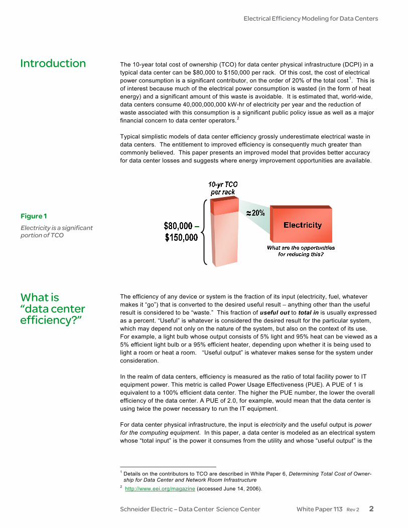
The 10-year total cost of ownership (TCO) for data center physical infrastructure (DCPI) in a typical data center can be $80,000 to $150,000 per rack. Of this cost, the cost of electrical power consumption is a significant contributor, on the order of 20% of the total cost1. This is of interest because much of the electrical power consumption is wasted (in the form of heat energy) and a significant amount of this waste is avoidable. It is estimated that, world-wide, data centers consume 40,000,000,000 kW-hr of electricity per year and the reduction of waste associated with this consumption is a significant public policy issue as well as a major financial concern to data center operators.2 Typical simplistic models of data center efficiency grossly underestimate electrical waste in data centers. The entitlement to improved efficiency is consequently much greater than commonly believed. This paper presents an improved model that provides better accuracy for data center losses and suggests where energy improvement opportunities are available. The efficiency of any device or system is the fraction of its input (electricity, fuel, whatever makes it “go”) that is converted to the desired useful result – anything other than the useful result is considered to be “waste.” This fraction of useful out to total in is usually expressed as a percent. “Useful” is whatever is considered the desired result for the particular system, which may depend not only on the nature of the system, but also on the context of its use. For example, a light bulb whose output consists of 5% light and 95% heat can be viewed as a 5% efficient light bulb or a 95% efficient heater, depending upon whether it is being used to light a room or heat a room. “Useful output” is whatever makes sense for the system under consideration. In the realm of data centers, efficiency is measured as the ratio of total facility power to IT equipment power. This metric is called Power Usage Effectiveness (PUE). A PUE of 1 is equivalent to a 100% efficient data center. The higher the PUE number, the lower the overall efficiency of the data center. A PUE of 2.0, for example, would mean that the data center is using twice the power necessary to run the IT equipment. For data center physical infrastructure, the input is electricity and the useful output is power for the computing equipment. In this paper, a data center is modeled as an electrical system whose “total input” is the power it consumes from the utility and whose “useful output” is the
1 Details on the contributors to TCO are described in White Paper 6, Determining Total Cost of Owner-
ship for Data Center and Network Room Infrastructure 2 http://www.eei.org/magazine (accessed June 14, 2006).
Introduction
Figure 1 Electricity is a significant portion of TCO
What is “data center efficiency?”

Electrical Efficiency Modeling for Data Centers
Schneider Electric – Data Center Science Center White Paper 113 Rev 2 3
amount of power for computing it provides, which can be represented by the amount of electrical power delivered to the IT equipment.3 Figure 2 illustrates this general model of data center efficiency. If the data center were 100% efficient (PUE of 1), all power supplied to the data center would reach the IT loads. In the real world there are a number of ways that electrical energy is consumed by devices other than IT loads, because of the practical requirements of keeping IT equipment properly housed, powered, cooled, and protected so that it can provide its useful computing. (These duties are the job of the data center’s data center physical infrastructure, or DCPI.) Non-IT devices that consume data center power include such things as transformers, uninterruptible power supplies (UPS), power wiring, fans, air conditioners, pumps, humidifiers, and lighting. Some of these devices, like UPS and transformers, are in series with the IT loads (because they provide the power path that feeds them) while others, like lighting and fans, are in parallel with the IT loads because they perform other support functions in the data center. Figure 3 illustrates these internal components of power consumption in the data center efficiency model.
3 The exact relationship between electrical power and “bits moved” is beyond the scope of this paper, but
electric power consumed by IT equipment is a fair measure of computing delivered, for the purpose of this analysis. Improvements in efficiency from reducing power consumption of the IT equipment itself are important but are not the subject of this paper.
Data center efficiency (PUE) = Total facility power IT equipment power
CCoommppuuttiinngg
FFaacciilliittyy TToottaall iinnppuutt
DDaattaa cceenntteerr UUsseeffuull oouuttppuutt
Power delivered to the IT load is a measure of useful output for the data center
DDaattaa cceenntteerr
IT load
Total facility input
power Power to IT
Figure 2 Data center efficiency is defined as the fraction of input power delivered to the IT load
Data Center
Power pathto IT
Powerto IT
UPSPDUCablingSwitchesPower to
data centerComputing
CoolingLightsFireSecurityGeneratorSwitchgear
ITEquipment
Power tosecondary
support
Data centerUSEFUL OUTPUT
FacilityTOTAL INPUT DCPI IT
Figure 3 Detail of power consumption in data center efficiency model

Electrical Efficiency Modeling for Data Centers
Schneider Electric – Data Center Science Center White Paper 113 Rev 2 4
The concepts of “useful” and “waste” in the data center efficiency model In an efficiency model, “waste” is everything other than what has been defined as the system’s useful output. Clearly, the data center’s DCPI (data center physical infrastructure) does other useful things besides provide power to the IT load – these are called “secondary support” in Figure 3. It could be argued that the useful output of these DCPI subsystems (cooling or lighting, for example) should also be considered part of the data center’s “useful output.” This is a frame-of-reference issue. The subject of this analysis is overall efficiency of the data center in producing its useful output, which is computing. Data centers are not built to produce cooling or fire protection or any of the other good things DCPI accomplishes. While these DCPI outputs are extremely useful to the internal workings of the data center in helping it to produce and protect its useful output (computing) they are not themselves “useful output” of the data center, nor is there any reason to believe that they must consume electricity. Non-power-path DCPI activities should be considered a necessary evil in support-ing the data center’s computing – therefore, in the data center efficiency model they are considered “waste” that should be minimized to the extent possible. All should be considered fair game for alternative designs and new technologies to reduce overall power consumption in the data center. For example, there are data centers that use "free cooling” methods, which take advantage of cool outdoor air using techniques such as heat wheels and plate-and-frame cooling. This can decrease the amount of electric power expended on cooling, which increases the efficiency of the data center. The “useful output” of the DCPI components themselves will be of critical concern later in this paper, in the analysis of individual component-by-component efficiency – a smaller frame of reference for efficiency within the data center – to reduce internal inefficiencies (waste) in the larger overall data center model. Where does data center power go? If the “useful” power of the data center (defined by PUE) is the power delivered to the IT loads, where does the rest of the power go? Figure 4 shows where power flows in a typical data center. Note that virtually all the electrical power feeding the data center ultimately ends up as heat.
CRAC/CRAH 15%
Humidifier 3%
Chiller 23%
PDU 3%UPS 6%
Lighting / aux devices 2%Switchgear / generator 1%
IT Equipment 47%PUE = 2.13PUE = 2.13
Figure 4 Power flow in a typical data center

Electrical Efficiency Modeling for Data Centers
Schneider Electric – Data Center Science Center White Paper 113 Rev 2 5
The data center represented in Figure 4 is a typical high-availability, dual power path data center with N+1 CRAC units, operating at a load of 30% design capacity. Note that less than half the electrical power feeding this data center actually is delivered to the IT loads. Using the PUE definition of efficiency, with 47% of the input power delivered to the IT load, the data center of Figure 4 is said to be operating at a PUE of 2.13.
Opportunities for increasing data center efficiency Data center efficiency can be increased in three ways:
1. Improve the internal design of DCPI devices, so they consume less power in doing their job
2. Match the sizing of DCPI components more closely to the actual IT load (“rightsizing”) so that the components operate at a higher efficiency
3. Develop new technologies that reduce the need for electric power to supply DCPI support functions (such as the “free cooling” techniques mentioned earlier)
(As will be shown, #2 provides the greatest immediate opportunity for increasing data center efficiency.) Figure 5 illustrates how reducing internal power consumption increases data center efficien-cy. While data center efficiency could be determined empirically by adding up the power con-sumption of all IT equipment and dividing by the total power input of the data center, the usual technique is to rely on manufacturers’ statements of efficiency for major components such as UPS and CRACs. This may be easier, but typically yields a seriously overstated efficiency that obscures any information potentially helpful in identifying opportunities for saving on electrical costs. Data center efficiency is more than “nameplate” component efficiency Manufacturers provide efficiency data for power and cooling equipment. For power equip-ment, efficiency is typically expressed as the percent of power out to power in; for cooling
Figure 5 Increasing data center efficiency
Efficiency misconceptions
Data Center
Power pathto IT Power
to IT
UPSPDUCablingSwitchesPower to
data center ComputingCoolingLightsFireSecurityGeneratorSwitchgear
ITEquipment
Power tosecondary
support
DCPI IT
Use less power hereUse less power here
Use less power hereUse less power here
Same power to IT loadSame power to IT load
Less input power neededLess input power needed

Electrical Efficiency Modeling for Data Centers
Schneider Electric – Data Center Science Center White Paper 113 Rev 2 6
EfficiencyUPS
CRACCoefficient of performance
KWoutKWin
at full load=
KW heat removedKWin
=
equipment, efficiency is typically expressed as a related parameter called “coefficient of performance” – the ratio of heat removed to electrical input power. The published values of efficiency for similar devices by different manufacturers do not vary dramatically, leading to the simplified view that the efficiency losses of a data center can be determined by simply adding up the inefficiencies of various components. Unfortunately, this approach does not provide accurate results in the case of real data centers. The use of manufacturers’ efficiency ratings causes users or designers to dramatically overesti-mate efficiency, and consequently underestimate the losses, of real data centers. Wrong assumptions Table 1 lists three common misconceptions that cause significant errors in data center efficiency models.
Wrong assumption Reality
Efficiency of power and cooling components is constant and independent of IT load
Efficiency of components – especially CRAC units and UPS – significantly decreases at lower IT loads
Power and cooling components are operating at or near full design load
Typical IT load is significantly less than design capacity of the DCPI components used
The heat produced by power and cooling components is insignificant
The heat output of power and cooling components is a significant cooling burden, and must be included when analyzing the inefficiency of the cooling system
These major errors compound each other, particularly at the lower IT loads that are typical of most data centers. As a result, data center electrical losses are routinely underesti-mated by a factor of two or even more. Fortunately, a simple model can be constructed that incorporates the above issues and provides for more reliable efficiency estimates.
Figure 6 Manufacturers provide a single efficiency number for each component
1
2
3
Table 1 Common misconceptions about data center efficiency

Electrical Efficiency Modeling for Data Centers
Schneider Electric – Data Center Science Center White Paper 113 Rev 2 7
An improved model for overall data center efficiency depends on how accurately individual components, such as UPS, are modeled. Characterizing power and cooling components by using a single efficiency value is the common method, but it is inadequate in real data center installations. The actual efficiency of a component such as a UPS is not constant, but rather a function of the IT load. Figure 7 shows a typical UPS efficiency curve.
Wrong assumption #1
Efficiency of power and cooling components is constant and independent of IT load
Note that when approaching very light loads, the efficiency of this device falls to zero. This is because there are some losses, such as control logic losses, that are independent of load. This constant loss that is independent of load is known by various names: no-load, fixed, shunt, tare, or parallel loss. This paper will use the term no-load loss. Figure 8 is another view of the same data as Figure 7. Note that, as the load decreases, the internal power consumption of the UPS (the “loss,” shown as the red portion of each bar) becomes a greater and greater fraction of the total power, thus reducing the efficiency percentage value. This is due to the no-load portion of the loss, which stays the same no matter what the load.
Efficiency improvement models
0%
10%
20%
30%
40%
50%
60%
70%
80%
90%
100%
0% 10% 20% 30% 40% 50% 60% 70% 80% 90% 100%
Load % of full power rating
UPS
Eff
icie
ncy
Figure 7 Typical efficiency of a UPS as a function of load

Electrical Efficiency Modeling for Data Centers
Schneider Electric – Data Center Science Center White Paper 113 Rev 2 8
The UPS described by the data in Figures 7 and 8 might be described as having 91% efficiency. However, this is the efficiency at full load, or best case scenario. At low loads, where most data centers operate, the description of this device as having 91% efficiency is grossly in error – for example, at 10% load the same UPS exhibits only 60% efficiency. Clearly, a single-parameter model for efficiency is inadequate in this case. The three types of internal device losses Careful inspection of Figure 8 reveals that the device loss (the red part of the bars) increases as the load increases. This is due to an additional loss – over the no-load loss – that is proportional to the load. There can even be a loss component on top of this (not evident in this chart) that is proportional to the square of the load, which is usually not significant but can make overall efficiency fall at higher loads. Table 2 shows typical values of these three types of losses for various types of equipment used in a data center. The losses are summed in the last column as the total loss for the component.
Most data centers operate in this range
UPS load% of full power rating
100%90%80%70%60%50%40%30%20%10%0%
Power delivered to load
UPS internal power consumption (loss) 91%90%
90%89%
88%86%
84%80%
75%60%
0%
EFFICIENCY
No-load portion of loss stays constant from full load all the way down to zero load
No-load loss is present even at no load
Figure 8 Effect of internal UPS loss on efficiency

Electrical Efficiency Modeling for Data Centers
Schneider Electric – Data Center Science Center White Paper 113 Rev 2 9
DCPI component No-load loss Proportional loss
Square-law loss
Total loss (single parameter)
UPS 4% 5% - 9%
PDU 1.5% - 1.5% 3%
Lighting 1% - - 1%
Wiring - - 1% 1%
Switchgear - - 0.5% 0.5%
Generator 0.3% - - 0.3%
CRAC 9% 0% - 9%
Humidifier 1% 1% - 2%
Chiller plant 6% 26% - 32%
From Table 2, it can be seen that by characterizing each type of device using no more than two parameters it is possible to create more complete models for the components used in data centers. Note that losses in this table are expressed as a percentage of full load rating of the equipment and that for actual loads less than full load, the percentage loss will change in the following way: • No-load loss: Loss percent increases with decrease of load
• Proportional loss: Loss percent is constant (independent of load)
• Square-law loss: Loss percent decreases with decrease of load
The typical UPS efficiency depicted in Figures 7 and 8 would not be accurately modeled by a single efficiency parameter, but has instead been appropriately modeled by the no-load (4%) and proportional loss (5%) parameters of Table 2.
+ + =
Table 2 Typical electrical losses of DCPI components expressed as a fraction of full load component rating

Electrical Efficiency Modeling for Data Centers
Schneider Electric – Data Center Science Center White Paper 113 Rev 2 10
The previous section explains that efficiency of power and cooling systems decreases significantly when used below equipment design rating. This means that any analysis of data center efficiency must properly represent load as a fraction of design capacity. Simple efficiency models that use only a single efficiency value to model equipment are insensitive to loading (efficiency does not change with load in these models). Yet it is a fact that in the average data center, power and cooling equipment is routinely operated well below rated capacity. The result is that such models significantly overstate the efficiency of real data centers. For each type of power or cooling component, there are four reasons why a component might be operated below its rated capacity: • The data center IT load is simply less than the system design capacity
• The component has been purposefully oversized to provide a safety margin
• The component is operating with other similar components in an N+1 or 2N configura-tion
• The component is oversized to account for load diversity
IT load is less than data center’s design capacity. The research is clear: The average data center operates at 65% below the design value. This situation is described in more detail in White Paper 37, Avoiding Costs from Oversizing Data Center and Network Room Infrastructure. The next sections of this paper will show that underutilization is a very large contributor to data center inefficiency. Component has been oversized to provide a safety margin. It is routine to oversize components in a common practice called “derating.” The idea is to avoid operating compo-nents near their capacity limits. It is possible to operate facilities with no derating, but derating values of 10-20% are recommended design practice for highly available facilities. Component is operating in an N+1 or 2N redundancy configuration. It is common practice to use devices in an N+1 or even 2N configuration to improve reliability and/or to allow concurrent maintenance of components without powering down the system. Operating the data center in such a configuration means the IT load is spread among more DCPI components, effectively reducing the components’ loading. For a 2N system, the loading on any single component is less than half its design value. Efficiency of a data center is therefore strongly affected by the operation of devices in N+1 or 2N configurations. Component is oversized to handle “load diversity”. This effect is subtle and best illu-strated by example. Consider a data center with a 1 MW load supported by a 1.1 MW UPS. Between the UPS and the IT loads are 10 power distribution units (PDUs), each feeding a portion of the IT loads. The question is: What are the ratings of each of these PDUs, and therefore what are they operating at for an average load? At first glance it would appear that if each were rated at 100 kW, the system design would be satisfied. Furthermore, if each PDU ran at full load the data center could run the entire load. However, in real data centers it is nearly impossible to assure balance of loads on PDUs. The load on a particular PDU is dictated by the nature of IT equipment in the region of the data center where the PDU is located. In fact, loads on various PDUs in real data centers often vary by a factor of 2. If a PDU feeds a section of data center that is physically utilized to capacity but is still not using the full power capacity of that PDU, then the remaining capacity on that PDU is unusable if the other nine PDUs are fully loaded. In this configuration, the only way to ensure full capacity of the data center is to substantially oversize total PDU capacity. The typical
Wrong assumption #2
Power and cooling components are operating at or near full design load
Effect of under-loading
Avoiding Costs from Oversizing Data Center and Network Room Infrastructure
Related resource White Paper 37

Electrical Efficiency Modeling for Data Centers
Schneider Electric – Data Center Science Center White Paper 113 Rev 2 11
oversizing of PDU capacity is on the order of 30% to 100%. As in previous examples, this oversizing degrades system efficiency. Figure 9 illustrates the need for PDU oversizing to support load diversity. It should be noted that the same problem that gives rise to PDU oversizing also drives oversizing of air handlers. Another major error in modeling data center efficiency is the assumption that heat output of power and cooling equipment (inefficiency) is an insignificant fraction of IT load and can therefore be ignored. In fact, heat generated by power and cooling equipment within a data center is no different from heat generated by the IT equip-ment itself, and must be removed by the cooling system. This creates an additional burden on the cooling system which creates the need for oversiz-ing of the cooling system, which creates additional efficiency losses in the cooling system. To properly account for these losses the cooling load must include both IT equipment and losses of any power and cooling devices located within the conditioned space. Based on the discussion above, it is possible to construct an improved model for data center efficiency. The improved model has the following attributes: • Components are modeled with a no-load loss, plus a loss proportional to the load, plus
a loss proportional to the square of the load
• Oversizing due to component derating is incorporated
• Underutilization due to N+1 or 2N designs is incorporated
• The cooling load includes both IT load and heat load due to inefficiency of indoor power and cooling components
• For a given data center installation, the model provides a graphical output of efficiency as a function of load, understanding that typical data centers operate well below design capacity
Figure 9 Effect of load diversity on PDU sizing
Effect of heat
Wrong assumption #3
Heat from power and cooling components is insignificant
Putting the piec-es together

Electrical Efficiency Modeling for Data Centers
Schneider Electric – Data Center Science Center White Paper 113 Rev 2 12
Implementation of the model is straightforward and obeys the following general flow: • Determine average degree of oversizing for each power and cooling component type,
provided derating, diversity, and redundancy factors
• Determine operating losses of each type of component using input load, fraction of rated load for the component type based on over sizing, no-load loss, and proportional loss
• Determine additional proportional loss due to the need for cooling system to cool power and cooling equipment within the data center
• Sum all losses
• Compute and tabulate losses as a function of IT load in the data center
A computer model based on these principles has been implemented to compute energy consumption in the Schneider Electric data center TCO analysis methodology, described in White Paper 6, Determining Total Cost of Ownership for Data Center and Network Room Infrastructure. Devices with multiple operating modes Some DCPI subsystems – air conditioners, for example – may have multiple operating modes with different efficiencies associated with each one. For example, some air conditioning systems have an “economizer” mode for periods of low outdoor temperature, where the system efficiency is significantly increased. Such devices cannot be modeled using a single efficiency curve based on the simple 3-parameter model (no-load loss, proportional loss, and square-law loss) described in this paper. To establish an efficiency model for a multi-mode device, a different technique is used. Fortunately, this technique is well-established and widely used in engineering. Devices that switch between different operating modes can be modeled over an extended period using a straightforward technique called “state-space averaging.” This is done by determining the relative amounts of time spent in the various modes, then generating a weighted average of the system’s output. This technique is readily applied to efficiency and loss calculations. To use the efficiency model described in this paper with DCPI devices having multiple operating modes, the fixed, proportional, and square-law losses first must be determined for each operating mode. Then, the overall loss contribution over an extended period is com-puted by multiplying the loss in each mode by the expected fraction of the time spent in that mode. For example, a complete description of a system with two modes would require three efficiency curves: • Efficiency curve in mode 1
• Efficiency curve in mode 2
• Expected overall efficiency curve, given a stated assumption of the amount of time spent in each mode
Equipped with a better model for data center power consumption, it is possible to make improved estimates of data center efficiency. Using typical values for equipment losses, derating, load diversity, oversizing, and redundancy, the efficiency curve of Figure 10 can be developed.
Determining Total Cost of Ownership for Data Center and Network Room Infra-structure
Related resource White Paper 6
Real-world efficiency

Electrical Efficiency Modeling for Data Centers
Schneider Electric – Data Center Science Center White Paper 113 Rev 2 13
Note that this curve of efficiency (PUE) vs. load (power capacity used) is considerably different from estimates based on conventional calculations that use manufacturers’ pub-lished component efficiency. A conventional estimate of efficiency of the data center described by Figure 10 would be a value of 60-70%, independent of load. Note the dramatic decrease in data center efficiency predicted by the improved model, particularly at lower loads where many data centers actually operate. The model shows for very lightly loaded data centers inefficiency effects can be dramatic. For example, given a data center loaded to only 10% of its rated capacity, for every ten watts delivered to the data center only about one watt actually reaches the IT equipment. The remaining nine watts are lost to inefficiencies in the data center physical infrastructure. Another way to look at these losses is in terms of financial cost. Figure 11 shows annual electricity cost of a 1 MW data center as a function of IT load. This is based on a typical highly available dual power path design with N+1 CRAC units. An electricity cost of $0.10 per kW-hr is assumed for this analysis.
Figure 10 Efficiency of a typical data center using the improved model
0.00
1.00
2.00
3.00
4.00
5.00
6.00
0% 10% 20% 30% 40% 50% 60% 70% 80% 90% 100%
Fraction of the power capacity used
PUE

Electrical Efficiency Modeling for Data Centers
Schneider Electric – Data Center Science Center White Paper 113 Rev 2 14
Figure 11 shows that total electricity cost of a 1MW data center ranges from $600,000 to $1,700,000 per year, depending on size of IT load. Note even if there is no IT load the cost is over $500,000 per year, driven by inefficiencies of power and cooling systems. At the 30% capacity utilization level of the typical data center, over 70% of electricity costs are caused by inefficiencies of power and cooling equipment. The model clearly shows that primary contributors to data center electrical costs are no-load losses of infrastructure components, which exceed IT load power consumption in typical situations. It is notable that no-load losses are ignored in conventional analysis; indeed, a review of product specifications shows that the important no-load loss specifications for power and cooling devices are not routinely provided by equipment manufacturers. An analysis of the data can quickly identify and prioritize opportunities for reducing losses and improving operating efficiency of data centers: • By far the biggest opportunity for savings is to reduce oversizing of data centers by
using an adaptable modular architecture that allows power and cooling infrastructure to grow with the load. Potential reduction in losses: 50%.
• Improve efficiency of cooling systems. Potential reduction in losses: 30%
• Reduce no-load losses of power and cooling components in the data center. Potential reduction in losses: 10%
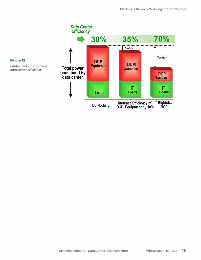
Figure 12 illustrates the relative efficiency entitlements from improved component efficiency and reduction of oversizing. A more detailed discussion of efficiency entitlements and efficiency improvement opportunities is the subject of White Paper 114, Implementing Energy Efficient Data Centers.
Efficiency entitlement
$0$200,000$400,000$600,000$800,000
$1,000,000$1,200,000$1,400,000$1,600,000$1,800,000$2,000,000
0% 10% 20% 30% 40% 50% 60% 70% 80% 90% 100%
Fraction of Power Capacity Used
Ann
ual E
lect
rica
l Cos
t
Total Electrical Cost
DCPI Load Electricity
IT Load Electricity
Figure 11 Annual electrical cost for a typical 1 MW data center as a function of the fraction of design capacity utilized
Implementing Energy Efficient Data Centers
Related resource White Paper 114
Electrical Efficiency Modeling for Data Centers
Schneider Electric – Data Center Science Center White Paper 113 Rev 2 15
Figure 12 Entitlements to improved data center efficiency

Electrical Efficiency Modeling for Data Centers
Schneider Electric – Data Center Science Center White Paper 113 Rev 2 16
Conventional models of data center efficiency typically overstate efficiency because they do not properly comprehend the degree to which equipment is oversized, nor do they compre-hend reduction of efficiency at the reduced loads where most data centers operate. An improved model provides more accurate numeric values for data center efficiency, as well as insight into where the losses go and how they can be reduced. Typical data centers draw more than twice as much power as IT loads require. The cost associated with this power consumption is a considerable fraction of the total cost of owner-ship of the system. All of the power consumed beyond the power needs of IT equipment is undesirable, and much of this may be avoidable. Oversizing of data centers is the single biggest contributor to data center inefficiency, suggesting that scalable solutions that can grow with IT load offer a major opportunity to reduce electrical waste and costs. The potential electricity cost savings for a typical 1 MW data center are on the order of $2,000,000 to $4,000,000 over a typical 10-year life of the facility. Due to the large amount of power and cost consumed by data center inefficiency, reduction of these losses should be a topic of paramount importance to all data center owners, as well as a significant issue of public policy.
Conclusion
Neil Rasmussen is a Senior VP of Innovation for Schneider Electric. He establishes the technology direction for the world’s largest R&D budget devoted to power, cooling, and rack infrastructure for critical networks. Neil holds 19 patents related to high-efficiency and high-density data center power and cooling infrastructure, and has published over 50 white papers related to power and cooling systems, many published in more than 10 languages, most recently with a focus on the improvement of energy efficiency. He is an internationally recognized keynote speaker on the subject of high-efficiency data centers. Neil is currently working to advance the science of high-efficiency, high-density, scalable data center infrastructure solutions and is a principal architect of the APC InfraStruXure system. Prior to founding APC in 1981, Neil received his bachelors and masters degrees from MIT in electrical engineering, where he did his thesis on the analysis of a 200MW power supply for a tokamak fusion reactor. From 1979 to 1981 he worked at MIT Lincoln Laboratories on flywheel energy storage systems and solar electric power systems.
About the author

Electrical Efficiency Modeling for Data Centers
Schneider Electric – Data Center Science Center White Paper 113 Rev 2 17
Avoiding Costs from Oversizing Data Center and Network Room Infrastructure White Paper 37
Determining Total Cost of Ownership for Data Center and Network Room Infra-structure White Paper 6
Implementing Energy Efficiency Data Centers White Paper 114
Browse all white papers
tools.apc.com
Browse all TradeOff Tools™
whitepapers.apc.com
Resources Click on icon to link to resource
For feedback and comments about the content of this white paper: Data Center Science Center [email protected] If you are a customer and have questions specific to your data center project: Contact your Schneider Electric representative
Contact us