electrical circuits - university of colorado boulder will be a voltage drop v1= i*r1 across the...
TRANSCRIPT

28-1 (SJP, Phys 1120)
Electrical Circuits: Most electrical phenomena (everything from light bulbs totoaster ovens to computer screens to lightning bolts..) involve the flow ofcurrent. Flow happens when you have a source of potential difference, and acircuit, a closed path for current to flow. (Since charge is conserved, chargesultimately have to go around in a circuit for the flow to be sustainable!)Let's start by thinking about sources of potential difference.HRW call any such device an "emf" device.You could think of "emf" as a funny spelling of "oomph". It's what provides theoomph, the required potential difference to drive current. Examples: generators,solar panels, fuel cells, or batteries.Batteries will be our "typical" emf devices:
Batteries: An example of an EMF device
Zinc ions (+ charged) get pulled off bychemistry (we won’t go into the details!) into theacid bath, leaving behind a residual “-” charge onthe Zn rod (terminal, electrode).
Meanwhile, electrons (- charged) are pulled off thecarbon rod into the acid bath, leaving a residual +charge on the C terminal.
That means the carbon side is now at a higher potential, VA > VB. Thispotential builds up, but if VA gets too high, the acid can’t pull electrons off anymore (the electrostatic attraction of e-’s back onto the + carbon rod will equalthe chemical attraction of the e-’s into the acid) So you reach an equilibriumwithΔV = VAB = VA - VB = some fixed value depending on the chemicals.
People usually drop the Δ, and just talk about “V”, the battery’s voltage. (Toobad, remember they really mean the difference in voltage between the twoelectrodes.) Some people will call this the EMF of the battery, using a curly Ethat I don't have in my fonts. EMF=work/charge, the electrical potentialdifference created.
If there's no circuit, the two terminals are at some potential difference, but nocurrent flows. If you connect something across them, current will flow, but theIDEAL battery maintains a constant voltage difference between the terminals!The EMF device provides energy to the charges moving around the circuit.
Carbon Zinc
Battery, or electric cell. VA VB
Acid

28-2 (SJP, Phys 1120)
In diagrams, we use a symbol for batteries:
The “+” and “-“ are often left off: the longer line alwaysrepresents the “+” side.
It’s a little like the symbol for capacitors, except the lines are different length.Capacitors and batteries have some common aspects, but they are still verydifferent. Capacitors don’t spontaneously build up a ΔV, like batteries do, andthey don’t always have the same value of ΔV.
You might expect that the “+” charges at the top of the C electrode would wantto go over to the “-” post. They are attracted. The +’s would drop in energy,ΔPE = qΔV: they’d like that, like rolling down a hill. They can’t go through theacid, though: the chemical reactions are stopping them. But what if you let themgo some other way, outside of the acid? E.g.:
Symbol for ideal wire:
Symbol for chunk of material thatallows currentthrough:
Now we’ve provided an outside path, a conductingpath, or circuit, for charges to flow from the + to -sides of the battery like they want to. There is acurrent flowing continuously through the circuit..This is a simple electric circuit.
This is NOT like discharging a capacitor (where the flow is quick, and then stopswhen the capacitor is discharged). The battery keeps maintaining a constantvoltage difference, the current is continuous.
chunk ofmaterial, e.g.metal.
ideal wire
Battery
ideal wire
I

28-3 (SJP, Phys 1120)
Example: A bike light’s battery drives 2A of current through the bulb. Howmuch charge has flowed in one hour?
Answer: I = Q/t, so Q = I*t = (2 A)* (3600 sec) = 7200 CThis corresponds to 7200 C / (1.6E19 C/electron) = 5E22 electrons have flowedthrough the bulb! (Sounds like a lot, although 2 A really isn’t an unusual current.Electrons are small.)
In that last example:Current (I) is the same everywhere along thiscircuit. That means= I through the wires == I through the “chunk of material” == I through the battery == I passing by point AIA = IB = IC = ID.
Also, VA= VB (because, there is no voltage change along ideal wires!) Be veryclear: VA refers to the value of voltage at point A. It's a number. It doesn't referto a difference. Similarly, VC= VD (again, because there is no voltage change, orvoltage difference along ideal wires.)
However, VA-VD = “V of battery” (which we REALLY should call ΔV, butpeople rarely do) is fixed, V>0.Look at the picture and convince yourself that this meansVB-VC= VA-VD=V (of battery) (which we should really call ΔV!)The order of those terms matters: VB is higher than VC.
I
A
C
B
D

28-4 (SJP, Phys 1120)
There are several analogies that might help you think intuitively about V, I, andR in circuits.
Analogy #1: Voltage tells about electrical potential energy, so think ofgravitational potential energy instead, as the analogue.
• Think of flowing charges as people sliding around at a ski area.• Think of batteries (which lift charges up to high voltage) as chair lifts that liftpeople up to high (gravitational) potential.• Think of resistors (which allow current flow, but eat up energy) as bumpymogul runs, which let people ski past, but slow you down.
I added a new circuit element here, aswitch.As shown, it’s “don’t pass”,
Unfortunately, this is called an “openswitch”, (but that means the run is closed,no current can flow. )
As shown, we have an “open circuit”, the gate is forbidding flow: no flow ofskiers, no current. (People will build up briefly at the top, but the lift operatorswill frantically call down and say “hold up, no more people!” and there’ll soonbe no flow of skiers anywhere)
When you close the switch (which unfortunately means “open the run”) skiers(current) flows. In steady state, equal numbers of skiersgo UP the lift every hour as go DOWN the run everyhour.
The ski lift is a pump, a battery, giving skierspotential energy, keeping the current flowing. If the liftdies, the flow of skiers halts.
The lift raises your potential energy. You’re not allowed to ride the lift DOWN,you have to ski.
The “flat smooth” parts are ideal wires. Skiers can freely wander forwards orbackwards at the top (or bottom) with no change in energy.
Ski Lift Moguls!Steep downhill.
Switch (gate) open
Flat, smooth,bottom of hill.
Flat, smooth,top of hill.
Ski Lift
Switch (gate) closed

28-5 (SJP, Phys 1120)
Lots of bumps in the mogul means lots of resistance. People ski slowly. Only asmall number of people can go down the hill every hour. So, only an equal smallnumber of people can go up. (They better not let any more people on the lift thancome down, otherwise there’s a buildup of people, which is forbidden at this skiarea!)The resistance here is high, the current is small.
If the ski run is smooth and easy => LOW resistance => lots of people will godown in a short time. There’s a large current of skiers. The lift has to bring lotsof people up, the steady state current is high.
If the run ices up (no resistance at all) we have big trouble. People get hurt, thelift goes crazy trying to bring everyone up fast enough, because they’re backdown at the bottom essentially instantly. The lift will quickly break down, it’llfry. It’s a “short circuit”!
If lift #1 raises you V1 feet, and lift 2 raises you V2 feet,you’ve gone up a total of V1+V2 feet.(We call this “batteries in series”. It’s like theexample problem a few pages back.)
On the way down, you lose EXACTLY the same height (potential energy,voltage) as you gained from the lift on the way up. That’s just conservation ofenergy.
Inside the mogul run (R), people (+ charges) flow DOWNHILL, from highvoltage to low voltage.Inside the lift (battery), people (+ charges) are lifted UPHILL, from low voltageto high.
We’ll come back to this analogy later, when we have more complicated circuits.It’s not perfect, but sometimes it can help you physically picture what’s goingon.
V1+V2
V2
V1
- +
+
-

28-6 (SJP, Phys 1120)
Analogy #2: Water flow. (Physicists really like this analogy, but frankly myintuition about pipes and pumps and pressure isn’t much better than my intuitionabout circuits! But here it is for you to think about, anyway.)
Think of current as “gallons of water/sec”Think of voltage as “water pressure”.Think of wires as pipes, and resistors as constrictions in pipes.
is like
If P1 = P2 (no pressure DIFFERENCE), then there is equal force on the water inthe middle. There’s no flow. Similarly, if V1=V2, there’s no difference involtage across the resistor, and I = ΔV/R = 0.
On the other hand, if P1>P2, you have high pressure on one side (like, e.g. thefaucet), and a constriction (e.g. the hose) and low pressure on the far side (e.g.the air outside the hose), and water will flow. Just like current through a resistorwith a voltage drop.
So a circuit looks like this:
islike
Pressure P1
Pressure P2 constricted
pipe
lowpressure
highpressure
constricted pipe pump
big pipe
I
High V
Low V
Voltage V1
Voltage V2
R
28-7 (SJP, Phys 1120)
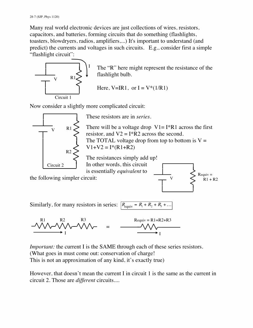
Many real world electronic devices are just collections of wires, resistors,capacitors, and batteries, forming circuits that do something (flashlights,toasters, blowdryers, radios, amplifiers,...) It's important to understand (andpredict) the currents and voltages in such circuits. E.g., consider first a simple“flashlight circuit”:
The “R” here might represent the resistance of theflashlight bulb.
Here, V=IR1, or I = V*(1/R1)
Now consider a slightly more complicated circuit:
These resistors are in series.
There will be a voltage drop V1= I*R1 across the firstresistor, and V2 = I*R2 across the second.The TOTAL voltage drop from top to bottom is V =V1+V2 = I*(R1+R2)
The resistances simply add up!In other words, this circuitis essentially equivalent to
the following simpler circuit:
Similarly, for many resistors in series: Requiv = R1 + R2 + R3 +K
=
Important: the current I is the SAME through each of these series resistors.(What goes in must come out: conservation of charge!This is not an approximation of any kind, it’s exactly true)
However, that doesn’t mean the current I in circuit 1 is the same as the current incircuit 2. Those are different circuits....
I
R1 V
Circuit 1
R1 V
R2
Circuit 2
Requiv = R1 + R2 V
R1 R2 R3
I
Requiv = R1+R2+R3
I

28-8 (SJP, Phys 1120)
Here’s a different circuit. We say R1 and R2 are “in parallel”:
This time, the current I is NOT necessarily the samethrough R1 and R2.
The current divides up: I1 goes left, I2 goes right.
(Conservation of current, however, does tell us thatI = I1 + I2, can you see that?)
It also says I at the bottom (going into the battery)is exactly the same as I at the top (leaving the
battery)
Note: the voltage across R1 is exactly the same as the voltage across R2! Thisis an important point, stare at the picture and try to understand why. Think ofthis as two different ski runs. Both have the same top and bottom (the sameheight, the same voltage), but they have different resistances, so differentnumber of skiers/hour. (Different currents through each resistor)
Or, you might think of water flowingthrough pipes:Here, the difference in pressure (likevoltage difference) is exactly the samefor both pipes (pressure at the top ofeither is identical, pressure at thebottom of either is identical, so thedifference across either is identical) butthe current through each will bedifferent.
The total current is just the sum of thetwo currents, I = I1+I2
R1 V
R2
Circuit 3
I2 I1
I
I
fixed, lowpressure
fixed, highpressure
constricted pipe 1 pump
pipe 2
I2 I1
total flow, I

28-9 (SJP, Phys 1120)
The previous parallel circuit (#3) is essentially equivalentto the following simpler circuit:
In this situation (resistors “in parallel”) I claim
1Requivalent
=1R1+1R2
+1R3
+K
We can prove it mathematically(if you’re interested):It comes from the fact that I = V / Requiv ,but conservation of charges (current) says
I = I1 + I2 + I3 + K =VR1
+VR2
+VR3
+K
= V * 1R1
+1R2
+1R3
+K
= V / Requiv
Examples of equivalent resistances:1
Requivalent=
1100Ω
+1
100Ω= .02 Ω−1 ,
i.e. Requivalent = 1 / (.02 Ω−1 ) = 50Ω
1Requivalent
=12Ω
+11Ω
=1.5 Ω−1 ,
i.e. Requivalent = 1 / (1.5 Ω−1 ) = 0.67Ω
1Requivalent
=12Ω
+10Ω
= (0.5 + ∞) Ω−1 =∞ Ω−1,
i.e. Requivalent = 1 / (∞ Ω−1 ) = 0. Ω
(The last is a short circuit, 0 resistance. All the current is happy to flow throughthe 0 Ω side!)Note that R_Equiv always comes out less than any of the individual parallel R's.That means, if there are two (or more) ways for the current to go, there is LESSoverall resistance to flow.
(More ways for current to flow makes it easier for the current to flow. More skiruns at a resort means you can get more people skiing: more current, less overallresistance.)
100 Ω
100 Ω
= 50 Ω
2 Ω
1 Ω
= 0.67 Ω
2 Ω
0 Ω => (short circuit!)
= 0 Ω
R1 R3
R2
I
Requiv V
28-10 (SJP, Phys 1120)
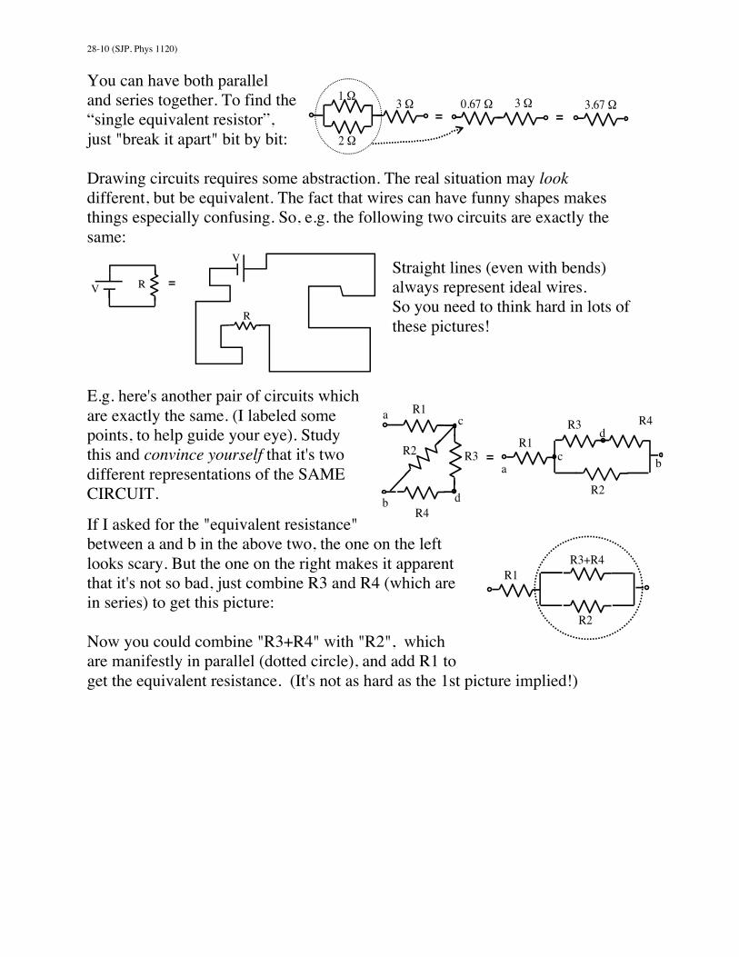
You can have both paralleland series together. To find the“single equivalent resistor”,just "break it apart" bit by bit:
Drawing circuits requires some abstraction. The real situation may lookdifferent, but be equivalent. The fact that wires can have funny shapes makesthings especially confusing. So, e.g. the following two circuits are exactly thesame:
Straight lines (even with bends)always represent ideal wires.So you need to think hard in lots ofthese pictures!
E.g. here's another pair of circuits whichare exactly the same. (I labeled somepoints, to help guide your eye). Studythis and convince yourself that it's twodifferent representations of the SAMECIRCUIT.
If I asked for the "equivalent resistance"between a and b in the above two, the one on the leftlooks scary. But the one on the right makes it apparentthat it's not so bad, just combine R3 and R4 (which arein series) to get this picture:
Now you could combine "R3+R4" with "R2", whichare manifestly in parallel (dotted circle), and add R1 toget the equivalent resistance. (It's not as hard as the 1st picture implied!)
R V =
V
R
R2 R3
R3
= R1
b
R4
R4 a
b R2
a
d
c d
c
R1
1 Ω
2 Ω
3 Ω 3 Ω =
0.67 Ω 3.67 Ω =
R3+R4 R1
R2

28-11 (SJP, Phys 1120)
Here's yet another example of identical circuits. ALL the pictures representexactly the same situation! Again, study them all, and convince yourself thatthere's no difference!
All those circuits are just 3 resistors in parallel. I personally prefer the firstdrawing, because it makes it visually obvious that the voltage V across all 3resistors is exactly the same. (Like 3 parallel runs down the ski hill) By the way,this setup is pretty much how houses are wired up for appliances: here's oneMORE drawing, which is pretty much equivalent to all the ones above:
V
R2 R3 R1 Stereo Toaster Light Bulb
Plug Plug Plug
I
fuse
(The funny symbol on the left represents not a battery but an alternating currentV=120 V AC. The fuse shuts off current to all 3 appliances if I exceeds about15-20 A)
R2 R3 = R1 V
V
R1
R2
R3
V
R3
R2 R1 = V R1 R2

28-12 (SJP, Phys 1120)
Another example. Here's a more complicated circuit, let's find the currents I1, I2,and I3. And, let's find Vab, the voltage difference between points a and b.
Look at R2 and R3. They're inparallel.
So we can combine them intoan effective single resistor.
The circuit is equivalent to this one:
I know what R/ / is because1R/ /
=1R2
+1R3
=120Ω
+120Ω
= 0.1Ω−1,
i.e. R/ / = 10Ω.
But now you can see we have two resistors in series. Thus, this circuit in turn iseffectively equivalent to the next one:
Life is easy at this point!
Use V = I1 Requiv,givingI1 =(10 V)/(40 Ohm) = 0.25 A.
This tells us I1 (the same in any of the diagrams!)To find Vab, go back a step to the "equivalent circuit" just above.
In that picture, you can see thatVab = I1*R/ / = 0.25 A * 10 Ohm = 2.5 V.To find I2 and I3, you go back yet another step, to the very top-most picture.(Note! Vab is the same across resistors 2 and 3)
Vab = I2R2 ⇒ I2 =Vab / R2 =2.5V / 20Ω = 0.125AVab = I3R3 ⇒ I3 = Vab / R3 =2.5V / 20Ω = 0.125A(Also notice: I2+I3 = .125+.125 = .25A = I1, which makes sense!)
R2 = 20 Ω R3 = 20 Ω
R1=30 Ω
10V
I1
a
b
R // = 10 Ω
R1=30 Ω
10V
I1
a
b
R Equiv =30+10 Ω = 40 Ω 10V
I1
b
28-13 (SJP, Phys 1120)
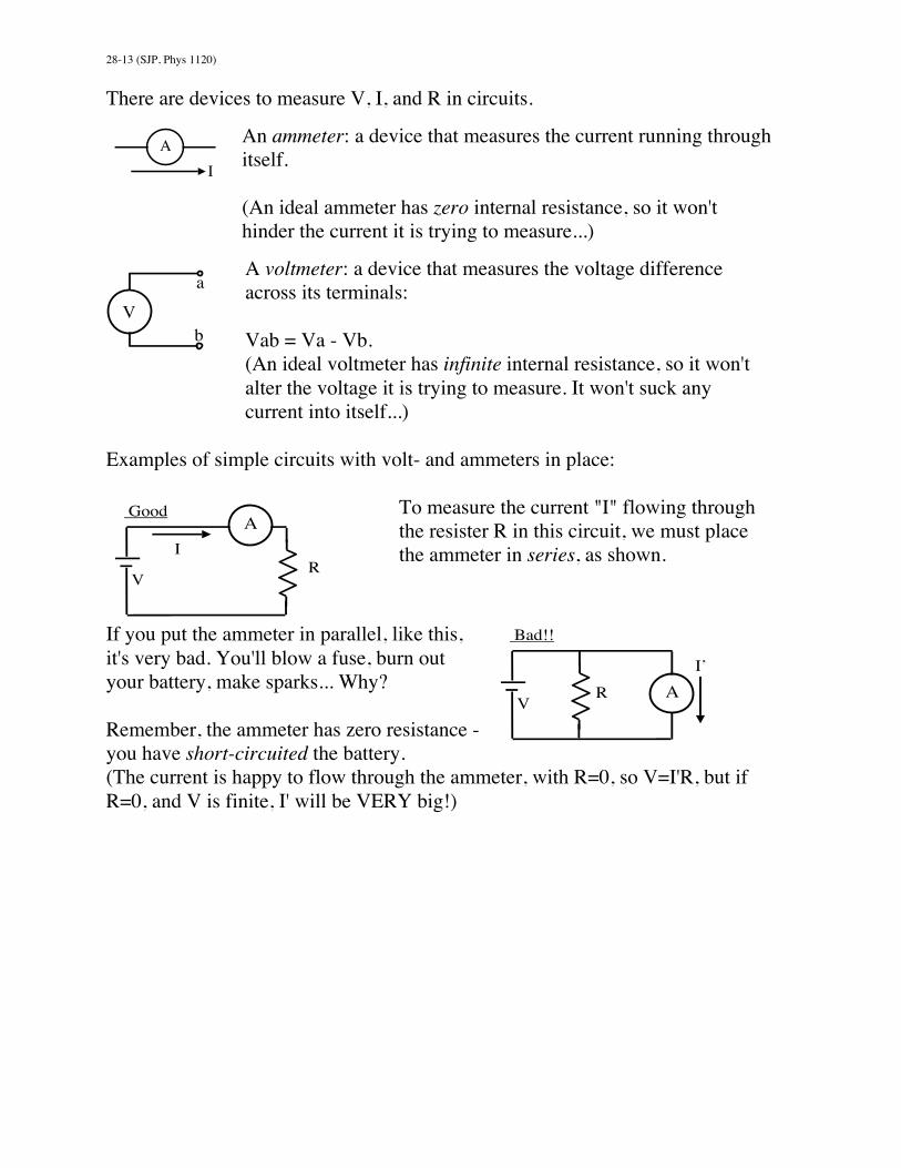
There are devices to measure V, I, and R in circuits.
An ammeter: a device that measures the current running throughitself.
(An ideal ammeter has zero internal resistance, so it won'thinder the current it is trying to measure...)
A voltmeter: a device that measures the voltage differenceacross its terminals:
Vab = Va - Vb.(An ideal voltmeter has infinite internal resistance, so it won'talter the voltage it is trying to measure. It won't suck anycurrent into itself...)
Examples of simple circuits with volt- and ammeters in place:
To measure the current "I" flowing throughthe resister R in this circuit, we must placethe ammeter in series, as shown.
If you put the ammeter in parallel, like this,it's very bad. You'll blow a fuse, burn outyour battery, make sparks... Why?
Remember, the ammeter has zero resistance -you have short-circuited the battery.(The current is happy to flow through the ammeter, with R=0, so V=I'R, but ifR=0, and V is finite, I' will be VERY big!)
A I
a
b V
R V
I A
Good
R V
Bad!!
A I’

28-14 (SJP, Phys 1120)
To measure the voltage "V" across the resistor, youmust place the voltmeter in parallel, as shown. Thevoltmeter will read off "V" for you
This circuit is bad. Remember, voltmeters havevery LARGE internal resistance. In this circuit, nocurrent can flow! (V=IR, R is huge, so I =0).
There will be no current, no voltage drop across the meter, it will simple readzero. Nothing will "burn out" like in the previous bad example, but you won't getthe reading you were interested in!
Note: real batteries always have some small, unavoidable internal resistance "r"in them. We can usually neglect it, but in real life, if e.g. you short circuit abattery, the current is large but never infinite due to the small but finite "r".
A real battery can be "modeled" in the following way:
Remember, our text writes an idealvoltage source as “EMF” (with acurly E) instead of V.
If you ever need to think about circuits with real batteries instead of ideal ones,just add in a small “internal resistance” r next to the battery. As batteries get old,the internal resistance gets larger (and so they put out less current)
Have you ever noticed that if you start your car with the lights on, the lightsdim? That’s because of the internal resistance of the car battery- as currentflows, there is some voltage drop across “r”, which means less voltage for thelight bulbs...
R V
Good
V
I
R V
V Wrong!
r (tiny) V (real)
(“Real” battery) V
=
(“ideal” battery)

28-15 (SJP, Phys 1120)
Finding R_equiv piece by piece, like we've done, usually works fine. Butsometimes, circuits get a little too complicated. E.g.
You can still find the currents and voltages throughout, using ideas we call"Kirchoff's rules". (There's nothing especially new here, we've alreadyintuitively seen and used the rules!)Kirchoff's first rule is a statement of conservation of current (charge): "whatevercurrent goes in, must come out".
At this junction "a" (which might be part of a biggercircuit), I1 = I2 + I3Current Entering = Current Exiting
Just be careful to watch the arrows. You will be drawingarrows for currents, and they might point either way. E.g. in this picture:
I1 + I3 = I2Current Entering = Current Exiting
(Note the direction of I3's arrow)
Example: Look at the junction labeled "a".Here, I = I1 + I2 + I3(I enters, the other three exit)
(Look back at the discussion about householdwiring. We had this same diagram.I is the total current drawn by your house. I1, I2,and I3 are currents in the individual appliances.)
I1 a
I2
I3
or V V
(2 batteries!)
I1 I3I2
I
V
a
I1 a
I2
I3

28-16 (SJP, Phys 1120)
Kirchoff's second rule says "The sum of voltage changes around any closed loopis always zero". (This is just conservation of energy.) Think of our ski-liftanalogy, where voltage <-> height. As you move around the ski area, you go upand down, but if you make a loop (ending up right where you started), the totalsum of all rises plus all drops will add to zero!
Example: Consider the following circuit (by now familiar!)Look at the loop labeled #1.
You can start wherever youwant, let's begin at the bottomand imagine "walking around"the loop in the directionshown.We first go UP the battery
(voltage change +V), and then we go DOWN the resistor R1, with voltagechange -I1*R1. It’s a drop: think hard about every minus sign here:
+V − I1R1 = 0 (Or V = I1R1 , which if you think about it makes sense!Resistor R1 has a voltage V across it, after all)
Alternatively, you could go around the loop labeled #4. (That's going around thewhole circuit, basically). Now you go up the battery, across the top (no voltagedrop there), and then down resistor R3. So Kirchoff's second rule says+V − I3R3 = 0 (Or V = I3R3 , again makes sense)
Another alternative: Loop #2. Thinking of this in the "skier analogy", loop #2 isfor backcountry skiers. You ski UP R1, and then back down R2. Kirchoff'ssecond rule would say
+I1R1 − I2R2 = 0 (Or I1R1 = I2R2 , both also =V, again makes sense)
Notice the signs. The I1R1 term is +, you're going UP the hill there (goingagainst the current), so your voltage is increasing....
R2 R3 R1 V I1 I2 I3
Loop #1
Loop #2
Loop #3
Loop #4(around the outside)

28-17 (SJP, Phys 1120)
Kirchoff's rules are fairly intuitive, except the signs can be tricky! Unfortunatelyit's critical that you get them right. Currents always have arrows (directions)associated with them, and so do the loops.
If you are going around a loop and encounter a resister with a currentlike this, then IF you are heading RIGHT -->, you're traveling WITHthe current, the voltage DROPS across R, so the change is -IR.
On the other hand, if you happen to be going around the loop the other way, <--,(so you're "fighting the current"), you're going UP the hill, change in voltage is+IR.
Batteries can also be confusing:
If you are going around a loop and encounter a battery like inthis picture, then IF you are heading RIGHT -->, you'retravelling from the low V side to the high V side of the battery,the change is +V.
On the other hand, if you are going around the loop the other way, (<--), thenyou're going DOWN the hill (down the battery) and the change in voltage is -V.(Think of the ski lift analogy)
Example: Let's figure out the currents in each of the resistors here.
The first step is to draw arrows forcurrents, and label them.
The direction you initially pick for the arrow is arbitrary!It doesn't matter. If you solve for, say, I1 in the picture above, and if it happensto come out negative, that just means the real current is heading the OPPOSITEway from the arrow you drew. (So, it'd be left, in the picture above.)
R
I
low side
V
high side
V1= 10 V
V2= 25 V
R1= 5 Ω
R2 = 50 Ω
I1
I3
I2
I4

28-18 (SJP, Phys 1120)
Before proceeding, try to avoid making up too many different symbols/labels forcurrents. E.g., in this example, look over on the left. I4 is entering the battery(labeled V1) and I1 is leaving. But Kirchoff's rule #1 says "what goes in, mustcome out". That's true everywhere, including batteries. So I4=I1. Why make upa different label? Just replace I4 with I1! There are then only 3 unknowns,rather than 4...
Here's the circuit again, with currents (and a few points) labeled.
What we're after is I1, I2, and I3.
Look at junction "a", we have I1 + I3 = I2 (Eq'n 1)(current in = current out: watch the arrows!)That's ONE equation, for three unknowns! We
need two more.
It turns out, in this case, that no more "current junctions" (i.e. Kirchoff's firstrule) will help. We could TRY, look e.g. at point b.
At point b, Kirchoff's first rule says I2 = I1 + I3.(Current in = Current out)But that's the same equation we had before!
So we use Kirchoff's second rule for our other two equations.Here's the circuit one more time, with some loops labeled:
Let's follow Loop #1.
We can start wherever we want,e.g. at point b, and go around.Watch all the signs!
+V1 − I1R1 − I2R2 = 0 (Eq'n 2)
We climbed UP the battery V1, it's +. We went DOWN both of the resisters R1and R2 (i.e. we went WITH the current), so they're both voltage drops, ornegative. Putting in numbers, we have+10V − I1 (5Ω) − I2 (50Ω) = 0 (Eq'n 2 with numbers)
We need one more equation. Just pick another loop (any one will do). E.g., let'sgo around loop #2, starting this time at point a.−V2 + I2R2 = 0 (Eq'n 3)
b
I2
I1 I3
V1
V2
R1
R2 I1
I3
I2
b
a
V1
V2
R1
R2 I1
I3
I2 b
a
Loop #1
Loop #2

28-19 (SJP, Phys 1120)
As always, the minus signs are important to understand. Look at the pictureagain: this time, when we pass battery V2, we are going DOWN the battery(from the "high" side to the "low" side indicated by the long and short horizontallines on the battery symbol, respectively.) That's a voltage DROP. It's like wetook the ski lift labeled V2 DOWN the mountain! That's why V2 got a minussign above.
Similarly, now we're climbing up the resistor R2. (We're fighting the current I2)That means we're going uphill: the voltage change is plus, so that's why we have+I2*R2.
Putting in numbers,−25V + I2 (50Ω) = 0 , or (solving for I2),I2 = 25V/50 Ohm = 0.5 A
We can plug this value for I2 back into Eq'n (2), giving
10V - I1*5 Ohm - (0.5 A)*50 Ohm =0, or (solving for I1)I1 = [10 V - 0.5A*(50 Ohm)] / (5 Ohm) = -3 A.
Finally, Equation 1 said I1 + I3 = I2, or (-3A) + I3 = 0.5 A,so I3 = 3.5A.
I1 came out negative. So we guessed wrong: current I1 is really heading left. It'sgoing INTO the left-hand battery. That's a little unusual, the big 25V battery onthe right is pumping current INTO the 10 V battery on the left, it's being"charged". Only specially designed batteries can be effectively recharged, formost normal ones this won't work. (You might damage the battery on the left.)
What does "charging" mean? Well... batteries can only put out so much totalcharge = current*time, and then the chemicals inside die. So for the short term,recharging is irrelevant, (the circuit diagram tells you what happens, regardlessof whether the battery is rechargeable or not) but after a long time, the voltage(and current) of a normal battery will become zero, unless you can recharge it!

28-20 (SJP, Phys 1120)
RC Circuits:
Putting capacitors into circuits is a bit of a funny business. E.g.,
The battery on the left will charge up the capacitor on the right.Charges move onto the top plate, and off the bottom plate, untilfinally Q=CV has built up on both plates. Then, no more chargeswill move.
So there's briefly a current (as charge flows from thebattery to the capacitor), but then the current stops.
Now consider a circuit with no battery at all, just acapacitor and a resistor. Let's begin with the capacitor all charged up
(like we just described), and the switch open, as shownhere.
Let's suppose we start with charge Q0, and voltage V0,across the capacitor.(V0 = Q0/C, of course)
At time t=0, we close the switch. What happens? The capacitor is now able todischarge! At first, a large current, I, will flow. (There's a voltage across theresistor at this point, and V=IR) This situation is similarto a simple "battery and bulb" circuit (like way back on P.19-1), but capacitors aren't batteries.
The capacitor runs down, quickly! Current doesn'tCONTINUE to flow, like it does with a battery.
So the current STARTS off strong (I0 = V0/R), but it will decay away with time.
V C
- - - - V C ++++ +Q I (briefly)
- - - - R ++++
Q0 C
- - - R +++
I
C
28-21 (SJP, Phys 1120)
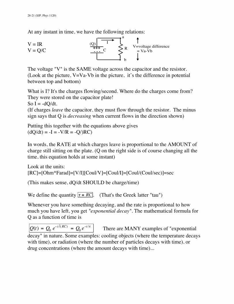
At any instant in time, we have the following relations:
V = IRV = Q/C
The voltage "V" is the SAME voltage across the capacitor and the resistor.(Look at the picture, V=Va-Vb in the picture, it’s the difference in potentialbetween top and bottom)
What is I? It's the charges flowing/second. Where do the charges come from?They were stored on the capacitor plate!So I = -dQ/dt.(If charges leave the capacitor, they must flow through the resistor. The minussign says that Q is decreasing when current flows in the direction shown)
Putting this together with the equations above gives(dQ/dt) = -I = -V/R = -Q/)RC)
In words, the RATE at which charges leave is proportional to the AMOUNT ofcharge still sitting on the plate. (Q on the right side is of course changing all thetime, this equation holds at some instant)
Look at the units:[RC]=[Ohm*Farad]=[V/I][Coul/V]=[Coul/I]=[Coul/(Coul/sec)]=sec
(This makes sense, dQ/dt SHOULD be charge/time)
We define the quantity τ ≡ RC . (That's the Greek latter "tau")
Whenever you have something decaying, and the rate is proportional to howmuch you have left, you get "exponential decay". The mathematical formula forQ as a function of time is
Q(t) = Q0 e− t /( RC) = Q0 e
−t /τ There are MANY examples of "exponentialdecay" in nature. Some examples: cooling objects (where the temperature decayswith time), or radiation (where the number of particles decays with time), ordrug concentrations (where the amount decays with time)...
- - - R +++
I
C
a
b
(Q) V=voltage difference = Va-Vb
28-22 (SJP, Phys 1120)
In the exponential decay formula, "e" is a number, e=2.718... It's a little like Pi.It's also called the "base of natural logarithms".e^something really means 2.718^something.(You do NOT use the "E" or "EE" key on your calculator! Look for the e^xbutton)
Since V=Q/C, we have (dividing that last equation through by C)
V(t) = V0 e− t/(RC) = V0 e
−t /τ .
At time t=0, you have e^(0) = 1, in other words V(0) = V0. (Duh)
If you wait till a later time, the formula tells you what the voltage is (or, theearlier formula tells you the remaining charge on the plates)
Example: When t=tau, (i.e. if you wait a time t=RC seconds, which is alsocalled waiting "one time constant"), then you haveV(τ ) = V0 e
−1 =1eV0 =
12.718
V0 ≈ .37V0 .The voltage has dropped to almost a third of where it started.
If you wait TWO time constants, i.e. t=2RC = 2*tau, thenV(2τ ) = V0e
−2 =1e2V0 ≈ .14V0
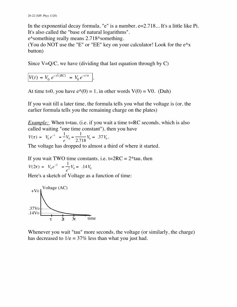
Here's a sketch of Voltage as a function of time:
Whenever you wait "tau" more seconds, the voltage (or similarly, the charge)has decreased to 1/e = 37% less than what you just had.
.14V0 .37V0
Voltage (AC)
time
+V0
3τ τ 2τ

28-23 (SJP, Phys 1120)
Example: Consider the following "RC" circuit:
Here, "tau"=RC=(10*10^-9 F)*(2000 Ohm) = 2*E-5 sec.
The time constant of this circuit is2E-5 sec. (pretty short)
Suppose you begin with Q0=50 microC of charge.(So V0 = Q0/C = 50.E-6C / 10.E-9 F = 5000 V = 5kV)The charge will begin to leak off (through R).
After 2E-5 sec (one time constant), you will haveQ(τ ) = Q0 e
−1 =1eQ0 ≈ .37Q0 ≈ 18.5µC left on the plates.
After 4E-5 sec (two time constants), you will haveQ0/e^2 = 6.8 micro Coulombs left.
You can plug ANY time into this formula. E.g., after one second,you have Q(1sec) = Q0 e
− (1sec)/ RC =Q0 e−1/ (2E −5) = 50µCe−5E 4 ≈ 0
It's long gone!
TV and computer monitors usually have BIG capacitors in them to store upcharges. They also have big resistors across those capacitors, and often havevery high voltage power supplies (converting the 120V at the wall to muchhigher voltages, many kV, inside). So Q0 = CV0 is large (lots of charge stored!)and tau = RC is also large (the time constant is big, it takes a relatively long timefor that charge to leak back off the capacitors). If you open up a monitor andstart poking around in there, you're liable to get into big trouble.
You provide a LOWER resistance path for thecharges to flow through - the current goesthrough YOU (with a smaller time constant, i.e.quicker!)
The inside of TV's and computer monitors can be pretty dangerous, even whenthey’re unplugged, because the capacitors in them can hold a lot of charge for along time (even after being disconnected to the external voltage source.)
- - - R =2 kΩ +++ C = 10 nF
- - - R +++
C R(you)