electrical experiments€¦ · an electric bell or other electro-magnet ... wheel and crank as fig....
TRANSCRIPT
GERNSBACK'S EDUCATIONAL LIBRARY N2.9
ELECTRICALEXPERIMENTS
ENiS;
RADIO PUBLICATIONS, 25 W. BROADWAY, NEWYORK, N.Y.

Suggest A Good Book Title
WIN TEN DOLLARS!SINCE 1908, the name Gernsback has been synonymous.
with scientific and radio literature. Since that time, manymillions of Gernsback magazines and books have been dis-
tributed and read by people all over the globe.Recently, Hugo Gernsback decided to place upon the market
a new, popular priced series of books under the name of GERNS-BACK'S EDUCATIONAL LIBRARY. It is the intent of thepublisher to continuously add books to the library, from time totime, under various titles. These books will cover a great manysubjects, which will not necessarily be restricted to radio orscience, but which will encompass many other arts.
It is Mr. Gernsback's plan to have all the books of uniformsize. Their price being extremely low, everyone will ultimatelybe able to possess the entire library, especially since they arepurchased piece -meal as the books are published.
Don t forget either, that Gernsback booksand magazines always have given you yourfull money's worth. The present series ofbooks again proves this. Never in the his-tory of technical publishing have you beenable to buy so much for so little money. Theanswer to this is in turning out a greaternumber of books and in large quantities.
In bringing out new books, we want yourhelp. Perhaps you have an idea for a certainbook title (subject for a new book) that youthink we should publish in one of these 10cvolumes. If you have such an idea, commu-nicate it to us; we will pay $10.00 for eachnew book title which we accept. If you sub-mit more than one title, write each one on aseparate sheet of paper. In case of a tie,identical prizes will be paid to the contest-ants.
Address all letters to
RADIO TITLE EDITORRADIO PUBLICATIONS25 West B'way NEW YORK City.
PRIZE WINNERSALFRED CETTIE
4115 Midvale AvenueSeattle, Wash.
Title: ALL ABOUT AERIALS,Book 4
RUDY RUZICKA3441 California Avenue
St. Louis, Mo.Title: BEGINNERS' RADIO DIC-
TIONARY, Book 5KENNETH WARNER
R. F. D. No. 2Burbank, Ohio
Title: HOW TO READ RADIODIAGRAMS, Book 7CLYDE SORRELL
504 North 10th StreetRockyford, Colo.
Title: RADIO FOR BEGINNERS,Book 8
(Watch the List Grow)
Copyright 1938. by H. GernsbackPrinted in U.S.

SimpleELECTRICALExperiments
ASIMPLE galvanometer, made bywinding a few turns of insu-lated magnet wire around a
ten -cent compass, has served to initiatemany a person into the mystic realmof electricity. As the illustration (Fig.1) shows, even holding a wire carry-ing a current over a magnetic com-pass will cause the needle to deflectto the right or left, depending on thedirection of the current through thewire. Hold the wire under the com-pass also and you will note that theneedle moves in the opposite direc-tion, showing that there is a whirlof magnetic force surrounding thewire.
To intensify thiS effect, we proceedto wind a coil of many turns of in-sulated wire around the compass. Ifyou have no compass, a magnetizedsewing neei:ie or piece of clock springwill serve our. purpose nicely. Make adent in the exact center of the steelstrip, so that it can swing freely onthe point of a needle or other pivot;the strip of steel can be magnetized bystroking with a magnet:
WIRE -It COO., COMPASS
COMPASS
BIN Seci/E 5 FOR AMP5
COIL OF WIRE
CIN PARALLEL FOR VOLTS
SIMPLE GALVANOMETER FIG. I
How to make a simple galvanometer
The more turns of fine wire youwind on the coil, the more sensitivethe galvanometer and the weaker thecurrent may be to which the instru-ment will respond. Also, the strongerthe current passing through the coil,the greater the deflection of the needle;thus the galvanometer can be used asa gauge of the current Strength (ifwound with heavy wire) and as anindicator of the voltage strength ifthe coil is wound with fine wire. To

2 Simple Electrical Experiments
POLE 3 AFTEROREAKINO MAGNET
TESTINGMAGNET POLESWITH COMPASS
NEEDLEFIG. 2
North and South magnetic poles attractopposite end of a compass needle
measure current the instrument is con-nected in series with the load, and forvoltage indications the device is con-nected in parallel with the circuit -see diagram.
Fig. C shows a neat way in whichto wind the coil of the galvanometerin a slot in a wooden block. The com-pass tits in the circular depressioncut out of the block, as becomesapparent.
Testing Magnet Poleswith a Compass
The compass is the electrician's bestfriend - see how it is used to tellnorth and south poles of a magnet inFig. 2. The north pole attracts onepole (the north -seeking pole of thecompass), while the south pole of themagnet attracts the opposite or south -seeking pole of the compass. The sameresults can be obtained by suspend-ing a magnetized needle on a pieceof thread. Fig. 2 shows how a brokenmagnet always manifests two poles, anorth and a south, no matter howmany times it is broken. A simple testwith a compass will prove this. Also,
explore the direction of the magneticfield about a magnet by moving thecompass about the magnet. If you takean electric bell or other electro-magnetand connect it to a battery, the result-ing magnetic field will be made mani-fest by exploring the vicinity of themagnet coil with a compass. A smallcompass is most useful for testing thepoles of a magnet: the poles of amotor field are often tested in thisway - the poles of a two -pole fieldshould be north and south respectively.Electro-magnets always show a northpole at one end of the coil and asouth pole at the other, the same asa permanent steel magnet. If alter-nating current is applied to a magnetcoil, the magnetic polarity changessixty times per second and thus cannotbe indicated by a compass needle.
Making anExperimental Magnet
A simple electro-magnet for experi-ments can be made from a pair ofelectric bell or telegraph sounder mag-nets, as shown in Fig. 3. If such mag-nets are not handy, a powerful magnetBe sure to connect magnet coils properlyso as to produce North and South poles
NOV TO CONNECT COILSTO GIVE N & S POLES

Simple Electrical Experiments
can be made by winding a dozen lay-ers of whatever magnet wire you have,around a piece of soft iron bar. Apiece of one-half inch iron bar (notsteel but wrought iron) bent U-shapedas in the sketch, will serve as the coreof a strong magnet. Each coil maycomprise a dozen layers of No. 18cotton covered or enameled copperwire, if the magnet is to be used on4 to 6 volts: use 15 layers of aboutNo. 22 magnet wire for battery vol-tages of 10 to 15 volts. Be sure toconnect the two coils so that the cur-rent goes around the second coil inthe opposite direction, so as to givenorth and south poles respectively:see diagram. If the current goes aroundthe coil or core in a clockwise direc-tion, a south pole results, and viceversa. In winding electro-magnets itis best to wind a piece of paper aroundthe iron core before starting the wind-ing.
3
Solenoids suck the iron core into the coU
Simple MotorFig. 4 shows how solenoids or suc-
tion type magnets are made: the coreslides in a brass or copper tube onwhich the coil is wound. Simple elec-tric motors can be made from asolenoid magnet connected to a fly-wheel and crank as Fig. 5 illustrates.Two pairs of magnets may be ar-
FLYWHEELCONTACT
PIN
SOLENOID COIL.
SPA 'NO
11114 wins TOSHAFT
INSULATED /otEvot.vme -/
/.._
46.-
..........
IRON CONE
COIL PIN --,-----`II11'1 . . 11111
, . .
lh'
Itql . 'tll 11.. SISDN CORE
110.taiCOPPER WIRE Loor
COPPERDose
BRUSH
FIXEDHAD/NTS
G.5
Two type' Di "isagsetic oscines"
4
IIDV A.060 CYCLES
A.0 MAGNET
^OLD TRANkfORMERCORE
ARMATURE
LArtiNATE 0IRON COREa POLE
A CMAGNET
,--"!OPT LIONWIN CORI
PI G.
COIL
In making A.C. magnets. themust be laminated
ranged as shown so that the currentto the moving magnets is cut off justas the poles approach each other. Thecontact is interrupted by a pin onthe shaft which hears against a spring.An old radio transformer (audio type)can be made into a motor by cuttinga slot in the iron core and arranginga copper disc to rotate in the slot;the disc will have to be spun byhand to get it rotating unless a start-ing cull (one turn of heavy copperhire) is placed in a slot on one ofthe pole -pieces as shown. This simpleloop of wire also gives the motor muchgreater strength.
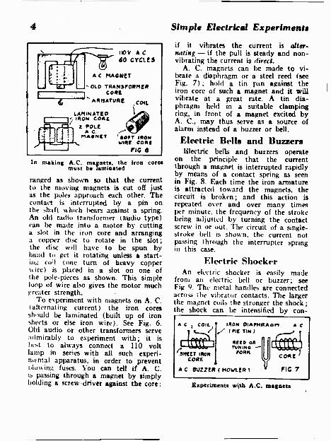
To experiment with magnets on A. C.(alternating current) the iron coresshould be laminated (built up of iron'sheets or else iron wire). See Fig. 6.Old audio or other transformers serveadmirably to experiment with; it isbest to always connect a 110 voltlamp in series with all such experi-mental apparatus, in order to preventi,lowing fuses. You can tell if A. C.is passing through a magnet by simplyholding a screw -driver against the core:
iron cores
Simple Electrical Experiments
if it vibrates the current is alter-nating - if the pull is steady and non -vibrating the current is direct.
A. C. magnets can be made to vi-brate a diaphragm or a steel reed (seeFig. 7); hold a tin pan against theiron core of such a magnet and it willvibrate at a great rate. A tin dia-phragm held in a suitable clampingring, in front of a magnet excited byA. C., may thus serve as a source ofalarm instead of a buzzer or bell.
Electric Bells and BuzzersElectric bells and buzzers operate
on the principle that the currentthrough a magnet is interrupted rapidlyby means of a contact spring as seenin Fig. 8. Each time the iron armatureis attracted toward the magnets, thecircuit is broken; and this action isrepeated over and over many timesper minute, the frequency of the strokebeing adjusted by turning the contactscrew in or out. The circuit of a single -stroke bell is shoun, the current notpassing through the interrupter springin this case.
Electric ShockerAn electric shocker is easily made
from an electric bell or buzzer; seeFig 9. The metal handles are connectedacross the vibrator contacts. The largerthe magnet coils the stronger the shock;the shock can be intensified by con-
A C I COIL IRON DIAINIRAOM(PIE TIN )
RENEL01
l'SmtaT IROR FORK
CORE
A.C.
A C BUZZER ( HOWLER t e FIG 7
Experiments with A.C. magnets

Simple Electrical Experiments 5
ARMATUREMAGNET CONTACTS
SPRING ---PUSH
BUTTONEIUZZER
STROKE. BELL
---- GONG
MAGNET,
ro31.1DUTTON
VIBRATINGElf LL FIG 8
A buzzes. - a single -stroke bell and a vibrating bell
netting an electro-magnet in series withthe handles. To regulate the degree ofthe shock, a potentiometer of .1 to .5megohm may be connected across thehandle circuit. To produce a stillstronger shock, coils of fine wire mayhe wound over the bell magnet coils,the handles being connected to thenne wire coils (the secondary over-wound coils are joined in series inthe usual manner, north -south fashion).All sorts of tricks can he played witha shocking apparatus like this: it maybe carried in the pocket and operatedfrom flashlight batteries, the shockingterminals taking the form of two piecesof metal mounted on a piece of fibreor bakelite carried in the hand. Boy -what a hot handshake your friendswill get!
Tricks withTelephone Receivers
Telephone receivers can be used forsome of the most interesting experi-ments imaginable. Two ordinary 75 -
ohm receivers can be hooked up toprovide a complete telephone circuit,as Fig. 10 shows. With a dry cell ortwo properly connected in the circuit,the talking efficiency is enhanced: tryreversing the terminals of the batteryand the phones until the best resultsare obtained. For one-way speech, acrystal type or Baldwin type phonemakes an excellent microphone ( nobattery required). At "C", the use ofa telephone receiver as an A. C. buzzeris illustrated : use a lamp or other re-sistance in series to protect the phone.A horn fitted in front of the phonegives a much stronger sound. A feed-back howler is made by placing a tele-phone receiver in front of a micro-phone. A telephone receiver is unbe-lievably sensitive to weak currents; itwill click if the current from a smallbattery is interrupted through the body.(Fig. E.) In fact, it has been said thata current of one ten -millionth of anampere will cause a response in a tele-phone receiver. A Baldwin type radio

6
head-ph3ne has been used to make anexcellent magnetic pickup for playingphonograph records (see Fig. 10).Electric Lamp ExperimentsOrdinary electric lamp bulbs can be
used for many novel experiments. Youcan determine whether a current isalternating or direct simply by mov-ing a magnet near the bulb. If the hotfilament pulls out in one direction only,the current is direct; but, if the fila-ment vibrates, it is alternating. An old-style carbon filament lamp is best forthis experiment. If a light stick is vi-brated back and forth in the fingersbefore a lighted bulb, the stick willappear to be stationary at times, asthe vibration speed coincides with thefrequency of the alternating current;if it is direct current, no such effectwill be noticeable. The same optical ef-fect is sometimes observed when anelectric fan is operating in the lightfrom an A.C. excited lamp (Fig. 11).
Simple Electrical Experiment.
Neon Lamp ExperimentsNeon lamps can be used for a simple
stroboscope experiment, see Fig. 12.Here we use an induction coil to ex-cite the neon lamp. By adjusting thevibrator on the ignition coil, it be-comes possible to get the effect ofmaking the fan blades stand still. Neonlamps are useful as fuse testers etc.;and they are handy for testing theignition systems of auto engines, thebulb lighting on only one wire andshowing high -voltage leaks, etc.
Many beautiful patterns can be pro-duced by placing a neon bulb behinda television scanning disc (see Fig. 13),such as used a few years ago for tele-vision; the disc may be made of card-board or fiber with a spiral of tinyholes around it. When this disc is fas-tened on to a fan motor shaft andwhirled before a neon lamp connectedto the loudspeaker terminals of a radioreceiving set, very wonderful designs
KILL sox HANDLE,
t4VA v.SAT
10 OM/9RHEOSTAT
CONTACTS
BUZZER .1
1
BAKELITE box(on w000)
k
IL% VOLTCELLO
10 OMIK RHEOSTAT
FIG. 9
Electric shocker made from a buzzer

Simple Electrical Experiments
2 BELL WIRES / A
miKE TEL. REC./
lilt OATD
FEED -BACK HOWLER
t75 OHM RECEIVERS75 OHMTEL REC
METALHANDLES
TELREC
11
TEST OF CURRENTTHROUGH BODY
1I0V LOWWATTBULB
110 V A.C.0".A.0
5,/C
BUZZER
BALDWINPHONE
(CAP ne.mvoo)LevEst
FPIVOT
--- NEEDLE
E PHONOGRAPHFIG 10PICK-UP
Experiments with a telephone receiver
are visible as the voice and musicmodulate the current. Changing thespeed of the motor also provides achange in the designs.
If you own a so-called violet -rayhigh -frequency apparatus, you will findthat ordinary lamps as well as neonlamps may be lighted on only onewire! If you hold an ordinary lampbulb in the hand and approach it to thehigh -frequency terminal of the Oudincoil, the lamp will glow with a purplisheffluence (fine spark discharge) verypretty and very weird! (See Fig. 14).To make a striking effect, tie severallamp bulbs on a stick and connect thebase of one with a tinfoil cap fittedover the glass end of the next bulb,etc. In this way you have a high fre-quency "wand" at slight expense. Toobtain an unusual effect, fasten twoor more neon (or plain lamp bulbs)on a piece of fiber or wood, so as to
be revolved by a motor, and providea brush or contact spring to carry thehigh -frequency current to the revolv-ing bulbs.
Fig. 15 shows a simple and mostuseful thermostat: it is made from apiece of thermostatic metal and bendswith changes in temperature. With con-tacts above and below it as shown,the device can be made to ring a bell
MAGNET
STEADY PULL ON(FILAMENT SHOWS
DIRECT CURRENT
VIBRATINGFILAMENT
'SHOWS A.G.
MOW TO TELL IF CURRENTA.C. OR D.C. FIG.II
To tell if current is A.C. or D.C.

8 Simple Electrical Experiments
LIGHT! WHENSPARKCOMES
FAN REFLECTOR
ADJUST VIORATORTO MAKE_FAN BLADEAPPEAR TO PIANO
STILL
BAT
NEON EWLE.
SPARKCOIL
FIG 12
Neon lamp experiments - see page 6
for low temperatures and a buzzer ora lamp for high temperatures, or vicevera. The moving strip can be madeIrani pieces of copper and steel rivetedtogether. The use of a thermostat forcontrolling a furnace blower motor isshov.n. This device might he used tostart an electric fan in the summertime and for a hundred and one otherpurposes.
Induction ExperimentsInduction experiments are perha 1),
the most mysterious and entrant mgII) the layman. Your friends will begrually my,titied at some of the elfedsobtained by this apparatus. All youneed is a pair of coils, old transformerwindings or a pair of old motor fieldcoils will do. Connect a 110 -volt lamp.any size, in series with the coil usedas the primary, to be on the safe side.A low -voltage lamp may he connectedto the secondary coil and, as this coilis moved away from the primary coil,the lamp gets dimmer (See Fig. 16). Ifyou own nr can borrow an A. C. volt-meter, you can then demonstrate the
marked change in voltage of the in-duced current in the secondary, as thecoils are separated more and more.Next, try placing an iron wire or lam -
NEONTL/DE
MOTOR
MASK
TERMINAL! OfLOUD SPEAKERON RADIO
SPIRAL OF HOLES
REVOLVING DISC
PATTERNS,OF VOICE& MUSIC --
FIG 13
t\1111./c../\./\./
Voice patterns from a neon tube

Simple Electrical Experiments
mated sheet iron core into the coils,and note the tremendous increase instrength of the induced current in thesecondary.
The first experiments with inductionwere made without iron cores butengineers soon learned to improvethe efficiency by using iron. It mustbe finely divided or else it will heatwhen alternating current is applied tothe coils. Another experiment - trylinking the iron -core circuit togetherso as to provide a continuous iron pathfor the magnetic flux and note what adifference this makes. That is the rea-son why commercial transformers havetheir windings well intermeshed withthe iron core, in an effort to link themagnetic field as closely as possiblewith the windings.
A pretty experiment is to plunge asteel magnet into the primary coil, witha galvanometer connected to the sec-ondary As the field increases the cur-rent induced in the second coil flowsin one direction, and as the field dimin-ishes (with the withdrawal of the mag-net) the induced current flow is in theopposite direction.
The Induction Balance;The Hughes induction balance is a
sensitive device for demonstrating slightchanges in the field of a coil. To makeone you need to make four coils, allexactly alike, same number of turnsand size of wire, etc. These four coilsare connected as shown in Fig. 17, withspecial regard to the polarity. The pri-mary coils can be excited by a buzzer,as indicated. The telephone receiver inthe secondary circuit will indicate nosound when the coils are balanced.Each coil may have 100 turns of No.28 magnet wire, wound on a 3 inch
9
TINrOtt. CAPS 110 V LAM"1./IRE
nevoLvir.oSTAR ERECT
HIGH -FREQUENCY COIL J FIG 14
Home-made "glow tubes" forTesla experiments
dia. spool, all the coils being woundin even layers and exactly alike. Thecoils are arranged on wooden sticks,so that coils of a pair can be movedapart till the bridge is balanced.
Fun with CondensersCondenser experiments are always
interesting: Did you ever hold the ballof a Leyden jar (or even a radio filtercondenser terminal) near a rapidlymoving belt, store up a charge in it
STRIP orTHERMOSTATIC
METAL
buzzes,.
1111nalalI
COPPER a STEEL STRIPSRLRRIVETEDTOY THERMO-
., !TATROTOR --
FIG.15
Experimental thermostat

-TEL RECEIVER
ALL COILSWOUNDEXACTLY
ALINE
ORDINARYPiece - BUZZER
OF METALDISTURBSBALANCE
10 Simple Electrical Experiments
AS AIR GAP A13 iNCRCASEDLAMP BECOMES
DIMMER
TRY IRON CORESIN COILS
YAY CLOSEDIRON CORE
PLUNGING MAGNET INTOPRIMARY COIL INDUCESCURRENT IN SECONDARY FIG 16
Induction experiments - iron cores intensify the results
and then present it to an unsuspectingfriend? Did we say friend!?
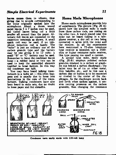
Fig. 18 shows how tinfoil and papercondensers can be tested by applying110 volts A. C. through a lamp. Ifthe condenser is of quite high capacity,the lamp will light bright: lower capac-ity condensers give a dimmer light. Inthis way the relative capacity can be
01 "')COND
INDUCTIONBALANCE
SV
FIG 17
111.-SAY.
The induction balance
judged. These radio type condensersoften hold their charge for quite awhile and many a shock has been ex-perienced by suddenly shorting one ofthe filter condensers with the hands.The way to discharge such a condenseris by means of a piece of wire. TheLeyden jar condenser is merely a(potash) glass bottle, coated inside andout with tinfoil, with a terminal fromthe inner foil coating brought outthrough the top of the jar to a brasshall. Ordinary (lead) glass dissipatesthe charge, and a glass free from leador other metal salts must he used, if
the jar is to hold its charge.
"Talking" Condensers
Talking condensers are startling in-deed! The secret of this stunt lies inthe use of loose tinfoil and paper ele-ments. See Fig. 19. The condenser isexcited or charged by sending talkingcurrents into it from a telephone orother type induction coil. The fluctu-ating electric charges on the condenser
Simple Electrical Experiments
leaves causes them to vibrate, thusgiving rise to sounds corresponding tothe voice originally spoken into themicrophone. About a dozen waxedpaper leaves 5 x 7 inches may be used,the tinfoil leaves being cut a littlesmaller all around than the paper. Al-ternate foil leaves are comected to therespective terminals as shown. A smallspark coil may be used, if no tele-phone induction coil is handy. The"mike" is just an ordinary one of thecarbon granule type and the batterymay be one giving 6 to 12 volts: asmall "B" or "C- battery may be used.Remember to leave the condenser leavesloose -a rubber band or two can beused to keep the assembled elementstogether in loose fashion. In this waythe condenser can talk.
You may have heard talking trans-formers in a radio set - this often hap-
and is usually due to loose ironlaminations in the core of the trans-formers. Talking condensers have alsobeen heard in radio sets, due no doubtto loose paper and foil elemehts.
11
Home Made MicrophonesHome-made microphones provide lots
of experiments. The picture (Fig. 20 A)shows how the simplest mike is madefrom three carbon rods, one resting onthe other two. A watch placed near thismike can be heard ticking in a tele-phone receiver, a dry cell or two beingconnected in series with the mike andthe receiver. In all the experimentshere mentioned a 75 -ohm telephonetype receiver is intended, not a 1000 -ohm or higher resistance radio receiver,this type passing too small a current.
A second type mike, easily made(Fig. 20-B) employs polished carbongranules retained in a carbon or graph-ite cup behind a carbon diaphragm; thelatter may be of tin or other metal,thin bakelite, etc., and in this case acarbon disc or button is to be cementedor riveted to the center of the dia-phragm. As the diaphragm moves backand forth when spoken against, it cre-ates varying pressures on the carbongranules, thus changing the resistance
ORIICTNIC93 Of LUD' (RRIINT.MEDIUM OR ) INMATESLANG' OR aroma. CAPACITY OrCONOINSIR. NO LINT SHOWSOPEN a CIRCUITED CONDENSER
.,TO POWER PACK
ssAss."-
CHARGIN WICHARGINCONO CONO.
SALL
OUTERFOILCOAT
-- WIAI-INSULATIO
Top
INNER rou.COAT
CONTACT
FIG 18
Concleamr tests easily suds with 110 -volt lamp

12 Simple Electrical Experiments
Heise '7.
-TIN FOILPAPER
--TIN FOIL
KatiecoNotNigN
LEAVE,LOOSELY
STACKI.0
CONDEN5E1
Mine
s- INDUCTIONCOIL
BATTERY
FIG 19
The talking condenser - see page 10
in the mike continually. The currentin a receiver circuit connected to amike will therefore fluctuate in exactconformity to the voice.
Loud -Speaking TelephoneA loud -speaking telephone can be
made by winding the magnet coil ofthe special receiver shown at Fig. 20-C,
of about 4 ohms.The coil might be wound with No. 18magnet wire. The battery current orvoltage is varied to suit the length ofthe circuit and the particular micro-phone used.
Arc Lamps, Furnaces andWelding Experiments
Arc lamp and welding experiments
are easily carried out, the main thingto watch here being your eyes! Don'tlook directly at the electric arc, unlessyou first don a pair of dark smokedglasses! Also, remember that an archas very low resistance when the car-bons are in contact; so always con-nect some form of resistance in serieswith it. As soon as the arc has beenstruck, its resistance increases and afair resistance will ballast the arc. Thearc works much better with this ballastresistance, which helps to stabilize it.On A. C. circuits a choke coil is pre-ferable and may consist of a few lay-ers of No. 14 magnet wire wound ona brass spool (slit the spool to pre-vent its heating), and a movable lam -
73 OHMTEL RECEIVER,
3 CARBON ROOS ONER55 OH Lowse TWO
SIMPLEST MIKE-A-
CARSON0,^104RAGM
-B-
-MID ninePELT RUNS
CARSONLot"
POLISHEDCARSON
RAIN I
MIR( HORNSAT ;
11
4 TO 6 OHM RECEIVER'
DIAPHRAGM
COILCORE
SORT IRON YOKE
FIG. 20
Simple horns -made telephone apparatus

Simple Electrical Experiments 13
BALLAST RESISTANCE
A
ADJ.SCREW
M T.
CRUCIBLE
RESISTANCE
METAL ROD
MOLDER
D
,METAL"NwSLO
METAL
CHOKE F1C 21
Electric Arc, Furnace and Welder
inated iron (or iron wire) core canbe slid in and out of the coil for bestregulation. In any event the resistance(or choke coil) should be adjusted un-til the arc strikes and pulls out toabout V2 -inch length, the current be-ing about 5 to 6 amperes after thearc is struck.
Fig. 21-A shows a simple arc lampwith balanced feed arm. Fig. B illus-trates an arc furnace, the two carbonsbeing placed through holes in a crucible.A variable resistance is, of course, con-nected in series with the furnace. FigC shows the principle of electric arcwelding, the metal wire being slowlydrawn along the seam or joint. Thesurfaces should be well cleaned, andsmoked glasses used to protect the eyes.A resistance or a choke coil is con-nected in series with the welding arc.A searchlight is easily fashioned as inFig. D. housing the arc in a metalbox with suitable ventilating boles tocarry off the heat.
Static Electricity
Static electricity is all about us. Everwalk over a piece of carpet, draggingyour feet, and find that a spark wouldjump to a gas jet and light the gas?Static electricity is the answer! (Fig.22.) Rub a hard -rubber comb, rod orfountain pen with a silk handkerchief,and you will find it has become elec-trified and will attract light pieces ofpaper or pitch balls. Rub a cat's furbriskly just after the cat has come inout of the cold - then present onefifiger to his ear. Zowie - a sparkjumps and you're both surprised! Italways works for the author.
Another source of static charge isthat resulting from rubbing the backof a photo print briskly with a hand-kerchief -a spark can be drawn bypresenting a knuckle to the shiny sideof the photo. An interesting demon-

14 Simple Electrical Experiments
HARDRUBBER
A
RUBBING WITH 311.1:(\1CHARGES ROD. ITATTRACTS PAPER SITS
BRASS ROD
LIGHT FOIL ( GOLD ISBEST) JAMMED INSLOT WITH TIN-
FOIL
APPLYING CHARGEDROD CAUSES THELEAVES TO SPREAD.TOUCHING KNOBDISCHARGES THEM; RADIUM ALSO.
ftutfaiwa CATS FUR CHARGESHAND. IF FINGER 13 HELDNEAR EAR. .SPARK JUMPS
SULPHUR
GLASS
RUBBING BACK OF PHOTO -PRINT BOLDS UP CHARGE
SCUFFING FEET ACROSSCARPET CAUSES SPARKTO JUMP ro IIAOUNEK 0PIPE (GAS JET ETC )
FIG 22Instructive experiments with
stration of static electricity is to chargean electroscope, made as per sketch(Fig. 22). Thin gold foil leaves aredesirable, but thin metallized paper orbronze foil, etc., has been used success-fully. The main point about the electro-scope is to thoroughly insulate the metalrod supporting the foil leaves, by meansof a sulphur bushing. If a chargedhard -rubber rod is applied to the ballterminal of the electroscope, the foilleaves diverge and, if the insulation isgood will bold the charge for quitesome time.
This is the famous method for de-tecting the presence of radium. Radiumhas the faculty of causing ionizationin the vicinity of the electroscope and,when this occurs, the charge on theleaves leaks oft ! In this way lost radiumhas been located several times --oncein an ash pile!
static electricity
Electro-Plating
A simple experiment in plating with-out the use of batteries or dynamo isillustrated in Fig 23-A. A regular plat-ing bath set-up is shown at B. Theobject must be very thoroughly cleanedfor good results. At C a wax or otherimpression of a medal, etc., is illus-trated; to plate it, a coating of pow-dered graphite must be given it. Onemethod is to obtain a tube of graphitelubricant from an auto supply storeand squeeze some of the lubricant onto the object ; then it is brushed overit till an even bright coat results.
In the simple plating cell at A, adilute solution of sulphuric acid is putin a cell or container made by wrap-ping a few layers of blotting paper orwrapping paper around a mandrel or

Simple Electrical Experiments
stick. This unit is in turn placed in alarger jar filled with a solution of cop-per sulphate. The object to be platedis suspended in the copper sulphateand the graphite -coated object is con-nected by a copper wire with a zincrod placed in the tube filled with thesulphuric acid solution. In the platingcell set up shown at B the anode isa piece of pure copper for copper plat-ing, and the object to be plated is sus-pended from the negative wire or ter-minal as indicated. The solution in
the cell is copper sulphate for copperplating, nickel salt solution for nickel -plating, and in this case the anode isa piece of pure nickel. Reference toany good book will yield the data
and silver-plating, etc.
15
Dancing Figure
An electric bell can be utilized tomake a very entertaining toy or showwindow attraction, as Fig. 24 shows,
ROLL OrBLOTTING PAPER
ZINCOBJECT ROD
SOLUTION Of\COPPER SULPHATE1011 COPPER PLATING
4 TO 6 VOLTSD.C.
0114ECT
DILUTESUL.ACID
ARUDDER
SAND
RHEOSTAT
COPPER SULPHATEOR NICKEL SALTS
ANODE OfCOPPER OR
NICKEL
WAX OR PLASTERCAST TO BE
PLATED
GRAPHITE POWDERBRUSHED OVER CA -fir
TILL 5URPACE 13I:1Ni eliT
C
(PLASTER SHOULD SCSHELLACKED FIRST
FIG 23
Electroplating is inexpensive

16 Simple Electrical Experiments
-B-
SW.
SPRING
RAISING WINDOWCLOSES CONTACT OPENING DOOR
& RINGS SELL RINGS BELLCLOSED CIRCUIT ON WINDOWS ETC. 7
SW.
r1C-----'11.SON PRIMARY (LI WIRE IS CUTSAT. (1 CELL l' BELL RINGS
fOR A.C. PROM STEP-DOWN TRANS. (WITH RELAY
MAGNETS [SACRED AWAYFROM ARMATURE]
-C-
lb
SPRINGS
FIRE ALARM MEATMELTS WAX, CLOSINGciRCUIT IDEAL RINGS
RELAY -3ZOO TO SOO OHMS
DRY CELLS
FIG 25
Burglar alarm circuits, including a closed circuit; if win is cut, bell rings
The bell is mounted in a wood or otherbox with a smallpiece of wood or fiberfastened on the apper of the bell, sothat it will vibr e directly under thesuspended figure.. The doll is easily con-structed from pieces of cardboard piv-oted at all joints so that the limbs hangloosely and ready to move quicklywhenever the bell and platform vi-brates.
Burglar Alarm
Fig. 25 illustrates a simple thiefalarm: at A we see how an open -circuitspring is held open as long as thewindows is down, keeping the bell fromringing. If the window is raised thebell starts ringing. Fig. B shows howa door alarm is arranged: if the door
is opened, the spring contact closesand the bell rings. To fool the wisethief who elects to "cut" the wire, aclosed circuit alarm is employed - seeFig. C. A gravity battery or an Edisonprimary battery may be used and, insome cases, low voltage A. C. from abell -ringing transformer has been usedto keep the relay closed. With A. C.the air gap on the relay between themagnets and the armature should beopened up well to prevent the contactchattering. A couple of dry cells areused in the local bell circuit of the re-lay: the relay may have 200 to 300ohms or more. To make a 'simple firsalarm, a piece of wax may be placedbetween two springs as indicated atD. Fire melts the wax and springs dosethe circuit.
Simple Electrical Experiments 17
TESLA COIL
WITH FORD SPARK COIL
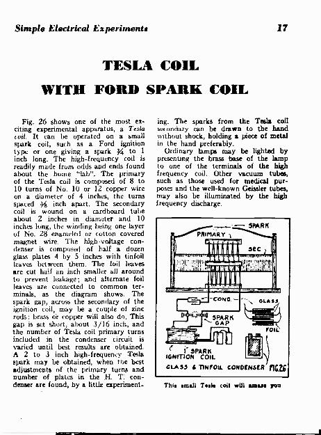
Fig. 26 shows one of the most ex-citing experimental apparatus, a Teslacod. It can be operated on a smallspark coil, such as a Ford ignitiontype or one giving a spark 34 to 1
inch long. The high -frequency coil isreadily made from odds and ends foundabout the home "lab". The primaryof the Tesla coil is composed of 8 to10 turns of No. 10 or 12 copper wireon a diameter of 4 inches, the turnsspaced 34 inch apart. The secondarycoil is wound on a cardboard tubeabout 2 inches in diameter and 10inches long, the winding being one layerof No. 28 enameled or cotton coveredmagnet wire. The high -voltage con-denser is composed of half a dozenglass plates 4 by 5 inches with tinfoilleaves between them. The foil leavesare cut half an inch smaller all aroundto prevent leakage; and alternate foilleaves are connected to common ter-minals, as the diagram shows. Thespark gap, across the secondary of theignition coil, may be a couple of zincrods: brass or copper will also do. Thisgap is set short, about 3/16 inch, andthe number of Tesla coil primary turnsincluded in the condenser circuit isvaried until best results are obtained.A 2 to 3 inch high -frequency Teslaspark may be obtained, when the bestadjustments of the primary turns andnumber of plates in the H. T: con-denser are found, by a little experiment-
ing. The sparks from the Tesla tollsecondary can be drawn to the handwithout shock, holding a piece of metalin the hand preferably.
Ordinary lamps may be lighted bypresenting the brass base of the lampto one of the terminals of the highfrequency coil. Other vacuum tubes,such as those used for medical pur-poses and the well-known Geissler tubes,may also be illuminated by the highfrequency discharge.
C PARKIGNfTION COIL
CLASS i TINFOIL CONDENSER fia2;
This small Task coil will amaze you

18 Simple Electrical Experiments
FENCE SHOCKERAn electric cattle fence shocker can
be made as in Fig. 27. A spark coil,such as a Ford ignition type, is use-ful for the purpose; and the high vol-tage "hot" wire from the secondary is
Electric fence shocker - it saves milesof wire and hours of time
connected to the fence wire, a singlecopper or other wire suspended about1 foot above the ground, using glassor porcelain insulators on sticks driveninto the ground. To intensify the shockaction, and also to lower the frequency,an extension rod is sometimes fastenedto the vibrator spring, with a movableweight secured to the upper end of thisrod.
Photo -Cell ExperimentsFig. 28 shows a few experiments with
photo cells and for these experimentswe need a source of light, such as abattery lamp in a box with lens andreflector. The beam of light from thelight box is focused on the photo -cellfor example: if a hand is interposedin the light beam, the cell's resistancewill change and the bell or other indi-
cator device joined to it will sound.As a fire alarm the device respondsif smoke passes up through the lightbeam. Another use for the photo cellis to automatically count people as theypass through the light beam, the celland its relay connecting to a ratchetfitted with numbered dials.
Induction Radio TelephoneA short-range wireless telephone, one
of the first ever demonstrated, is illus-trated in Fig. 29. A couple of coilsabout 2 feet in diameter are suggested;the transmitting coil, comprising about50 turns of No. 22 insulated wire, andthe receiving loop 100 turns of No. 32.The transmitter involves an ordinarymicrophone, a battery of a few dry cellsand a telephone induction coil. The re-ceiving loop connects to the primary ofa telephone induction coil and the sec-ondary to a pair of 2000 -ohm phones.A little experimenting may be necessaryto obtain best results, such as changing
LAMP
(9)
LIGHT-SENSITIVE,-, PHOTO -CELL
9!
7.. f,7IJ
SMOKE PASSING THROUGHLIGHT RAYS RINGS SELL
LIGHT
LIGHTRAYS
RELAY
COUNTER 1
PHOTOt RELAYCELLPIG. 28
Photo -cell experiments

Simple Electrical Experiments
the number of turns in the loop andvarying the voltage in the microphonecircuit.
At the transmitter a single buttonmike may be connected in series witha battery of 4,/2 volts or so and theloop antenna. For a simple receiving cir-cuit you may experiment with a pairof 75 ohms head -phones connected dir-ectly to the receiving loop. A better im-pedance match and therefore strongersignals can be obtained by connectinga matching transformer or inductioncoil through the loop or pair of phonesThis transformer is particularly desir-able if you should happen to use a pairof 2,000 ohm or higher impedance head-phones, which would make a consider-able mismatch with the loop impedance.
Where a longer distance than 15 ft.or so is to be negotiated with this in-duction type radio -phone, the receivermay have its sensitivity increased byusing a stage or two of audio amplifi-cation. The A.F. transformers used maybe of about 3 to 1 ratio and batterytype tubes such as the 1.4 or else the2 -volt type can be used, with about 90volts of "B" battery to supply the platecurrent. With such an amplifier a sensi-tive permanent - magnet type - loudspeaker may he substituted for thephones if desired.
Another suggestion where greaterrange is required is to make the loopsconsiderably larger. say about 4 to 5 ft.square instead of 2 ft. Also a vacuumtube amplifier stage or two may be in-serted between the microphone and theloop at the transmitter, so as to givea much stronger magnetic field andlonger transmission distance between heloops.
Electricity from FruitStick copper and zinc stripe into a
lemon and an electric current will be
19
75 OHM PHONES HEREINDUCTION COu. ) FIG 29Talking by induction
indicated on a galvanometer or a milli -ammeter. See Fig. 30. Try other fruitand also vegetables - a potato for in-stance. A source of current is thus ob-tainable for tests in an emergency.
Many other odd sources of currentare to be found besides those described.In some cases emergency test current hasbeen obtained by inserting zinc and cop-per strips into moist earth. Another ex-pedient is to immerse two stripe of met-al into a cup of vinegar. Another earthbatter used by one experimenter con-sisted of two pieces of metal buried atdifferent levels in the ground and con-necting these two buried metal platesto the test apparatus by lengths of insu-lated wire.
Yes - lemons and potatoes produceelectricity

20 Simple Electrical Experiments
HOW TO MAKEA steel screw driver may be mug-me-
tized by stroking it back and forth onsteel magnet as Fig. 31 shows. Strokethe tool from the center of the magnettoward one end, but always the sameend. At C the magnet is stroked overthe tool to be magnetized. Fig. B showshow a steel tool or other piece of har-dened steel can be magnetized by plac-ing it in a coil of several layers of insu-lated magnet wire, fed from a battery,either storage type or a few dry cells.
To maintain the strength of steelmagnets. keep a bar of iron or steelacross the poles when the magnet isnot in use.
MAGNETS
STROKING STEELTOOL FROM
CENTER TOEND
TOOL -.
TO RATS
A MAGNETIZINGCOIL
MAGNET
STRoRe TOOL wormMAGNET TO
MA4NETIZI IT
C111111D
TOOL'
SEEP IRON ARMATURE ONHORSE- SHOE MAGNET
B
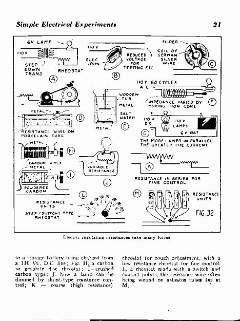
RHEOSTATSAND HOW TO USE THEM
Fig. 32 shows the application ofrheostats to various circuits. Many ofthese experiments can be carried outwith a step-down transformer, a bell -ringing type for example. The rheostat,or variable resistance for low -voltagecircuits. can be made of several dozenturns of iron or German -silver wire,wound on a porcelain tube or an asbes-tos one, with a slider arranged to moveover the wire In this way a lamp canbe dimmed, or the speed of a motorchanged at will. At B we see an electricsad iron used to cut down the voltagefor a test circuit. C shows a resistancecoil bent in the form of a circle. to pro-vide circular motion of the slider_ Dshows a rheostat used to regulate thespeed of a motor ; the more resistancecut into the circuit, the slower the mo-tor runs, and vice versa. In a pinch,
electricians often make use of a waterrheostats; here two metal plates (E) areplaced in a wooden pail or a barrelfilled with salt water or baking sodaeater. One of the plates can be movedup or down to vary the resistance; theplates can he of any metal available.
For A C circuits an adjustable im-pedance coil, Fig. F, proves valuable.A movable laminated sheet iron (oriron wire) core is slid in or out of thecoil to dim a light or vary the speedof a motor. The coil can be severallayers of insulated magnet wire, the sizedepending on the current to be passedthrough the circuit. For experimentalpurposes, try 5 to 6 layers of No. 16,bringing out Lips from the 3rd, 4th,and 5th layers. Fig. G illustrates howseveral 110 -volt lamps can be connec-ted in parallel to control the current
Simple Electrical Experiments 21
6V LAMP
,,,011111STEP )DOWN RHEOSTATTRANS
rRESISTANCE WIRE ONPORCELAIN TUBE
PETAL
47111t MIS"
CARBON DISCSMETAL
POwDE REDCARBON
RESISTANCEUN I TS
STEP IS41TCH1RHEOSTAT
O
CD,
II0 V
CLECIRON
METAL
VARIABLERE 5i3TANC
TYPE
REDUCEDVOLTAGE
FORTESTING ETC
SLIDER
COIL OFGERMAN -
SILVERWIRE
110 v 60 CYCLESA C -
1.100 OENTUB
METAL
SALTWATER
O
(IMPEDANCE VARIED ESTMOVING IRON CORE
110 VC
110 VLAMPS
6 V BAT
THE MORE LAMPS IN PARALLELTHE GREATER THE CURRENT
-1AAAVW
-10RESISTANCE IN SERIES FOR
F NE CONTROL
O RESISTANCEUNITS
FIG 32
Electric regulating resistances take many forms
to a storage battery being charged froma 110 Vt., D.C. line; Fig. IL a carbonor graphite disc rheostat ; I --crushedcarbon type; J. how a lamp can bedimmed by shunt -type resistance con-trol; K - coarse (high resistance)
rheostat for rough adjustment, with alow resistance rheostat for fine control.1., a rheostat made with a switch andcontact points, the resistance wire oftenbeing wound on asbestos tubes (as atM).

22 Simple Electrical Experiments
RECTIFIERSOne of the simplest rectifiers for con-
verting A.C. to D.C. is a crystal detec-tor formed of a metal point or needlebearing against a crystal such as carbor-undurn. This device has the faculty ofclipping off the half -waves in one direc-tion and passing all those in the oppo-site direction. In this way, for ex-ample, we can use a direct -current me-ter on an alternating -current circuit.Fig. 33-A shows a crystal rectifier inseries with a meter: only a small cur-rent is passed by such a crystal recti-fier of course. For larger currents therectifier at B may be used: here analuminum plate and a lead plate areimmersed in a jar containing a satura-ted solution of ammonium phosphate(a solution which will absorb no more
of the salts). This cell will pass cur-rent in one direction, hut not in theother. With plates about 4 by 5 inchesthe cell will pass about half an ampereor so.
One cell delivers only half -wave rec-tification and, to obtain full -wave rec-tification, four cells are hooked up asshown at C. The path followed by thecurrent at each half -cycle in such arectifier is indicated at D, this last dia-gram being for a copper -oxide dry -platerectifier. With electrolytic rectifiers ofthe aluminum lead -plate type it is oftennecessary to connect a load of a fewlamps across the rectifier, until theplates "form" (a thin gas film forms onthe plate).
o C TYPEMETER
AC
CRYSTAL (OR COPPEROXIDE) RECTIFIER
110 V.A C
A
FULL WAVE RECTIFIERt4 JARS) ALOP1INU14. LEAD
110Y. LAMPS
D.C.
ALUMINUM
PLATLEADE
PLATE
AMMONIUM PHOSPHATE SOLUTIONHALF -WAVE RECTIFIER
11401/3 CURSE NTON ONE SAL/
CYCLE
A C
SNOWS CURRENT//AON NEXT MALF
CYCLE ...../.:'TULL WAVE COPPER-
OXIDE RECTIFIER
D
Rectifiers of several types

Simple Electrical Experiments
SIMPLE MEASURINGINSTRUMENTS
23
TESTTUBE" -
IRONPLUS
SCALE
DALANCINGSPRING
SCALE
A
COIL
SPRING
NEEDLE
SOLENOIDCOIL ON
PIVOT ORFIBRE .MOLL
AMMETERS ARE" (, VOLTMETERS ARECONNECTED CONNECTED ACROSSIN SERIES DD CIRCUIT
MAGNETIZED STEEL
SCALE --,..
BRASS-,
sorTIRON CORE
;Fe
NEEDLE --
t MAGNETIZEDNEEDLES
'BRASS SPOOLe INSTEAD OFCOIL NAIR SPRING
D weicper TO FRETURN NECCILIL TO
ZERO
FIG 34
Home-made electrical Measuring Instruments
One of the simplest instruments formeasuring voltage or current is thatillustrated at Fig. 34-A. A coil whencarrying a current exerts its magneticpull on a soft -iron core resting on aspring, as the drawing shows. A lightspring may be used on top of the ironcore to "stabilize" it, and a calibratedscale is pasted on the glass or celluloidtube. The stronger the current, thegreater the pull on the iron plug; formeasuring amperes, the coil is wound
with heavy wire and for volts the coilis wound with fine wire. No. 16 insu-lated magnet wire is about right forcurrents of 1 to 6 amperes: for voltagesof 1 to 10, the coil may be wound withNo. 28 or 30 magnet wire. The coilbobbin can be 11/2 inches long and11/2 inches in diameter; the glass tubemay be about 1/2 inch in diameter, andthe iron core small enough to slidefreely inside the tube. A voltmeter isconnected across a circuit as shown in

24
Fig. B, and in series with the circuitfor current measurements.
A very simple solenoid (suctiontype) meter is shown at C; the actionis - the soft iron core is drawn intothe coil in proportion to the strength ofthe current or voltage, the same rulesholding - i.e., heavy wire for ammetersand fine wire for voltmeters. The coilcan be wound on a brass or fibre bob-bin, or copper will do. Cover the in-side of the spool with paper, glued on,before winding on the wire.
A type of measuring instrument easyfor the experimenter to build is ob-served at D. The coil may be woundon a brass or fiber bobbin; the movingelement is a small piece of clock spring,magnetized and fitted over the shaftso as to turn with it. It may be gluedin place if necessary. A few steel sew -
(7)
Simple Electrical Experiments
ing needles may be used instead of theclock spring, as shown at E, and ineither case the steel armature is tobe magnetized by strokinz with a steelmagnet before assembling the meter, thepivots being obtained from an old clockor other source. The bobbin may beabout 2/2 inches long, 3 inch wideand ). inch high. For an ammeter windthe bobbin full with No. 16 magnetwire, and for measuring volts wind itfull of No. 28 to 30 magnet wire. Inany case, the best way to calibrate themeter is to borrow another calibratedone. For a voltmeter you can mark di-visions on the scale as follows: one drycell 11/2 vts; two dry cells 3 vts; etc.To return the armature to zero it is asimple matter to tit a hair spring on theshaft of the meter (at F), or you mayjust depend on a balance weight fas-tened on the shaft.

Simple Electrical Experiments 25
HEAT OR COLD FROM JUNCTIONOF DISSIMILAR METALS
Fig. 35 shows how a current passingfrom bismuth to antimony, in a "cou-ple" containing these two metals, willproduce a cold effect: on the otherhand, if the current passes through thecouple or juncture in the opposite direc-tion, a heating effect is produced. Thethermoelectric couple is now widely em-ployed to measure temperatures of fur-naces, etc. The so-called Peltier effectof cold has not been put to industrialuse so far, at least not on a large scale;so here is a chance for our experimen-ters to put Mr. Peltier's discovery towork! The thermoelectric couple workson the principle that, if we apply heatto the juncture of two dissimilar wirestwisted electric cur-rent is produced whose strength dependsupon the degree of heat applied. A mi- in the commercial instruments, the me-croammeter connected to the couple in- ter is calibrated in degrees of hest (Fab.dicates the degree of temperature and, or Cent., etc.).
PELTIER CROSSPRODUCES COLD- /ROM
CURRENT
Z cossimiLAIIIwine&
TWISTEDTOGETHER
THERNOCouPLEPRoDuCts ELECTRICCuRRINT ,FNEN
Me ATE 0 F1635
Thermocouples are used in heat -measuringinstruments
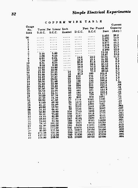
HANDY WIRE GAUGE11 you have on hand coils of wire
of unknown size. this size may he easilyfound by winding a coil one inch in
length on a form of any sort. Whenthis has hoen done, count the turns,which should be as closely spaced aspossible. Then refer to a taLile that givesthe number of turns per inch for vari-ous sizes and types of wire. For exam-ple, a one -inch winding of No. 24 s.s.c.will consist of 45 turns, as the tableshows.
WIRE TABLER. & S.
C; AT !GE DCC SCC DSC SSC18 19.6 22.3 22.3 23.622 30.0 34.0 34.0 36.624 35.5 41.5 41.5 45.330 55.5 71.3 71.3 83.134 70.0 97.0 97.0 120.0
B. & S.GAUGE ENAM.
ENAM.SCC
ENAM.SSC
18 24.0 ' 21.7 22.922 37.7 32.7 35.024 47.2 39.7 43.130 92.3 67.4 77.934 145.0 91.7 112.0

26 Simple Electrical Experiments
MUSICAL INSTRUMENTSFig. 36 is a picture of an easily made
electric chime, comprising a series ofbrass or bell -metal tubes, with an elec-tric hell mounted near each tube tostrike it whenever the current is switch-ed into it from the keyboard. The keysmay he old piano keys, or home-madeones of wood, mounted on a pivot baras shown. As each key is pressed, itcloses a circuit to the proper bell, andthe vibrating hammer plays that par-ticular chime. The bells can be madesingle -stroke if desired.
Electric CarillonThis was built by Hugo Gernsback
in his early experimental days and isshown at Fig. 37. You can make asmany octaves as desired and the musicis produced by electric bells playing orvibrating against bottles filled with wa-
Carefully selected bottles givepleasing sounds on this carillon
TUBES
BA
BELL
THREAD
BELLS
PIVOT)CONTACT,/ Nevi
r..J
SPRING')
(TO COMMONCONNECTION
BELLS -2
P /T
NETS FIG 36
HIGHNCTE3
MIDDLENOTES
LOWNOTES
(LARGERBOTTLES)
BOTTLES SUSPENDEDdY THREADS FRom
RODS
BOTTLE TUNEDBY ALTERING ----HEIGHT OF W ATER
METAL,BRACNETS
WOODENSUPPORT
ELECTRIC CARILLON '8". FIG 37

Simple Electrical Experiments
ter to different levels. The bottles canbe tuned by means of a piano or othermusical instrument: the small bottlesare used for the high notes and thelarge bottles for the lower notes. Thebottles are suspended on cords and thestrikers on the bells are fitted with
27
a better tone. You can try single -strokeon the bells by cutting out the vibratorcircuit but the writer prefers the vibra-ting tone. To tune the bells, differentheights of water are tried until the de-sired note is obtained when the bottle
wooden balls, instead of metal, to give is tapped
Film Dryer AN old electric fan and a heating unit from
a radiant type heater are assembled to pro-vide a blast of warm air to dry film rapidly.A poreclain electric light socket is clamped tothe center of the wire fan guard. This socketis connected in parallel with the line feedingthe fan motor, and a switch is put in serieswith it. The heating coil is a standard one, ob-tainable at any 10c. store. When the fan andheating unit are turned on, a warm, gentlebreeze dries prints or negatives in no time atall?
FAN BLADE MOTORGUARD Aix
HEATERCOIL
NEATER COILSOCKET
113 110V.OUTLET
40.1 ql.)WITLER'4
SWITCH (OPTIONAL))
MOTOR
T0110y. WIRING, DIAGRAM--At.AL AR
with a wooden mallet.
Removable Iron Tip
The tips of soldering ironssoon become corroded from theheat and are almost impossibleto remove when replacement isnecessary. The way to avoidsuch trouble is to remove thetip immediately upon purchas-ing a new iron and to dustgraphite lubricating powder ontothe portion of the tip which fitsinto the barrel of the iron, andalso sprinkle the graphite intothe socket in which this tip fits.This lubricant permits the tipto be removed at any time,while greases would be bakedand become useless.

28
Home-made Key
Wanting a practice key and not wish-ing to spend any money on one, I con-structed one out of apparatus found inthe odd parts box. Almost the entirekey is of wood, as the drawing shows.The .only metal parts are the stopsand contacts. Should metal be avail-able. the arm may he made of this in-stead of wood, and in this case oneof the connecting wires may be directlysoldered to the arm at the point whereit is attached to the hearing rod. Naibarc provided in the bearing plate andthe dowel rod which carries the keyarm. These are to keep the arm from
TO PRACTICEOSCILLATOR
KNOB
WOOOEN( DOWEL
OBEAChnila
RUBBERBAND
NAILSCDR STOPS
WRONG0r.sing too high or otherwise gettinginto an inconvenient position. Contactsmay he made through nails, screws orany other metal driven through the armand baseboard.
Simple Electrical Experiments
Batteryless Flashlight
Flashlights are often used aroundthe shack or work bench, and while itdoes not keep one broke to buy bat-teries for them, such expenditures arenot needed. I hooked up an old output
ASNLIGNTREGULAR
ANY OUTPUTTRANSP
TIP ,JACKS S THE TRANSF AREARRANGED iN A BOX TO MACE TmEUNIT PORTABLE (JACKS SKIwIC AS NERO
transformer, as shown in the accom-panying sketch, as power for the flash-light used to inspect receivers in myservice shop. Any output transformerwill provide the low voltage high cur-rent neiiessary for flashlight bulb oper-ation or, if one prefers, a filamenttransformer can he used, in which eventstandard pilot light bulbs can beoperated in the flashlight at their nor-mal brilliancy. And it's always readywhen needed.

Simple Electrical Experiments 29
SOLDER
STIOL1
TO MEETOf
AMPLIFIER
--- ',satyr
floomm=moommomme
Ilume-made Pickup
A simple and inexpensive phonographpickup can be made. from the parts ofan old non -electric pickup head andan earphone.
The needle holder for the electricpickup is removed from the old pickuphead and attached to the earphone inthe following manner: A Ya" hole isdrilled in port "A" ol the needle holderand is countersunk to accommodate aO-32 flathead screw. A hole is thendrilled in the bakelite cap of the ear-phone and is threaded with a 6-32 tap.The part "A" is then attached to theearphone cover by the short flatheadscrew. The end of part "B" is solderedto the diaphragm of the phone. Thelacquer on the surface of the diaphragmmust be scraped off first and care mustbe taken so as to not bend the disc.
Part ."13" is then placed between itspivot points and the points tightened togive the desired tightness. Vibrations ofthe diaphragm, caused by the record,produce an alternating current in thewindings of the mirphone; this alter-nating current is fed to an amplifier
which is in turn connected to a loud-speaker; a simple coupling system is
shown in the drawing. The quality ofthe pickup unit is fairly good.
SHADE 'TO FIT ..--.-eRACE
1/4" THICKFILE, 2°
4,,QN0
(*-22
LESS NANRADIUS OF HOLE -
DESIRED
Circle CutterA cheap and effective circle cutter
is an essential when building sets onmetal chassis or when cutting panels.The drawing herewith shows a cheapbut highly effective cutter of this type,which can be made from an old file.The tile may be softened by annealingit in a gas stove. This is done by heat-ing the tile to cherry red, then allowingit to cool slowly. The end is then sawedand tiled into the form shown in theillustration. After this, it is reheatedto cherry red and plunged into coldwater to temper it. The tang (or handleend) should be tiled down to fit thejaws of a standard brace. If it doesnut fit securely it will wobble, resultingin a ragged cut. This home-made tool
will prove an aid to the experimenter.
PLACEWOODENBLOCKUNDER
CHASSIS

30 Simple Electrical Experiments
HOME - MADE ELECTRIC
DRINK MIXER MOUNTS ON WALL
SMALL electric motors are availableon the market today at a very lowprice; one of the most useful appli-cations of such a motor is for the pur-pose of mixing drinks, or the stirringof solutions in the chemical laboratory.Our illustration shows how such a
motor may be screwed to one leg ofa large iron strap hinge, so thatthe motor with its attached mixermay be swung upward out ofthe way when not in use. Therheostat for regulating the motorspeed is optional, but is very de-sirable in the photo or chemicallaboratory. It may be madefrom a porcelain tube or anasbestos covered iron tube, woundwith a layer of about No. 16German silver or other resistancewire. The turns of the wire areplaced a slight distance apartand a spring slider is mountedso as to slide along a brass baras shown. In this way the cur-rent supply to the motor maybe regulated by changing the
amount of resistance in the cir-cuit. The mixing attachment maybe picked up in the "5 and 10"or it may be simply a wire ringsoldered or riveted to a brasssleeve which will fit snugly onto the end of the motor shaft.
Id
moToR
MOTOR
Tiewr PT5Lety
Variable speed mixer mounts on wall or cabi-net, and can be used for stirring drinks orbatter, whipping cream and other kitchen tasks

Simple Electrical Experiments 31
SIMPLE ARC WELDER FORHOME OR SHOP METAL WORK
A SIMPLE electric arc welder can be For A.C. operation an old trans -made cheaply from the few parts shown former core may be picked up for ain the accompanying sketch. First of few cents and a winding of severalall, do not forget to thoroughly pro- Ala Nixes twect your eyes with a pair of dark IRON COVER
glasses or goggles. To control theamount of current passed throughthe arc (which should be held downto a value of 5 to 10 amperes) aballast resistance is connected in se-ries with the arc. A resistance coil(or grid) works very well on directcurrent but for A.C. circuits an im-pedance or choke coil (primary win-ding of a small transformer willserve the purpose very well) worksmuch better and allows a more sta-ble arc to be drawn.
The ballast resistance may bemade by winding about 20 ft. ofeither German silver or other resis-tance wire around 4 porcelain tubes(or asbestos covered iron rods) laidout on a square 4" x 4" as shown.One side of the circuit is connectedto an adjustable clip, so that thecurrent can be regulated, and if youcan obtain an ammeter it wouldbe well to connect it in series withthe circuit and the current adjustedto a suitable value.
Tl
SAL AST AMMETER(RESISTOR HERE
RONSASE
ASBESTOSCLIP COv ERE TUBES
CHOKECOIL
ILO V., A C. rms=sco
layers of No. 14 D.C.C. copper wireplaced on one or both of the longerlegs of the core. It is well to bringout taps from each layer after the sec-ond, and diagram B shows how the ad-justable choke coil is connected in serieswith the arc.
The welder has a multitude of uses.It can be used to make long seams, joindissimilar metals, perform spot-weldingoperations, repair leaks, etc.
32 Simple Electrical Experiments
GaugeNo.
B& S
00012345
COPPER WIRETurns Per Linear Inch
D.S.C. S.C.C. Enamel D.C.C.
TABL E
Feet Per PoundS.C.0 Bare
2.4823.1303.9474.9776.2767.9149.980
CurrentCapacity
(Amp.)
88.9'70.955.744.135.027.722.0
6 5.44 5.60 12.58 17.5
7 6.08 6.23 15.87 13.8
8 6.80 6.94 19.6 19.9 20.01 11.0
9 7.64 7.68 24.6 25.1 25.23 8.7
10 8.51 8.55 30.9 51.6 31.82 6.9
11 9.58 9.60 38.8 39.8 40.12 5.5
12 10.62 10.80 48.9 50.2 50.59 4.4
13 11.88 12.06 61.5 63.2 63.80 8.5
14 13.10 13.45 14 77.3 79.6 80.44 2.7
15 14.68 14.90 16 97.8 100 101.4 2.2
16 16.40 17.20 18 119 124 127.9 1.7
17 18.10 18.80 21 150 155 161.3 1.3
18 20.00 21.00 23 188 196 203.4 1.1
19 21.83 23.60 27 237 247 256.5 .86
20 23.91 26.40 29 298 311 323.4 .68
21 26.20 29.70 32 370 389 407.8 .54
22 28.58 32.00 36 461 491 514.8 .43
23 31.12 34.30 40 584 624 648.4 .34
24 33.60 37.70 45 745 778 817.7 .27
25 36.20 41.50 50 903 958 1031 .21
20 39.90 45.30 57 1118 1188 13(W) .17
27 42.60 49.40 64 1422 1533 1639 .13
28 45.50 54.00 71 1759 1903 2067 .11
29 48.00 58.80 81 2207 2461 21107 .084
30 51.10 64.40 88 2534 2893 3287 .067
31 56.80 69.00 104 2768 3483 4145 .053
31 00.20 75.00 120 3137 4414 5227 .042
33 64.30 81.00 130 4697 5688 6591 .03331 68.60 87.60 140 6168 64410 8310 .026
35 73.00 94.20 160 6737 8393 10480 .02130 78.50 101.00 190 7877 9846 13210 .017
37 84.00 108.00 195 9309 11636 16660 .0133.: 89.10 115.00 205 10606 13848 21010 .01039 95.00 122.50 215 119(17 18286 26500 .00840 102.50 130.00 230 14222 .24381 33410 .006
41 112 00 153.00 240 17920 30610 42130 .00542 124.00 168.00 259 22600 38700 53100 .004
Radio Lesson FREE
J. E. SMITHPresident
See how I train you at home toBE A RADIO TECHNICIAN
Mail Coupon for a 32 -pagesample lesson FREE. It showshow N. R. I. trains you forRadio at home in spare time.I'll also send my 64 -pagebook. "WIN RICH RE-WARDS IN RADIO." whichdescribes many fascinatingRadio lobs.
Future Looks Bright for Trained RadioTechnicians, Operators
The Radio Repair Business is booming. Profitsare large and future prospects are bright. Broad-casting Stations, Aviation Radio, Police Radio,Loudspeaker Systems, Radio Manufacturing, allemploy trained Radio men at good pay. Alsothink of the NEW jobs that Television, FrequencyModulation, Electronics, other Radio developmentsPromise for the future. You have a real oppor-tunity. I will train, you to be ready to cash inwhen amazing Radio developments are releasedfor unlimited use.
My Method Helps Many Make $5,$10 a Week EXTRA While Learning
Many N. R. I. students start to flu Radiosin spare time while learning. Learning fromIllustrated N. R. I. lessons and building and test-ing circuits with Radio ,parts I send makes you"old friends" with Radio before you know it.You run your own spare time shop, get practicefixing Radios, get paid while training.
Find Out What N.R.I. Can Do For YouMAIL COUPON NOW for FREE sample Lesson
and 64 -page illustrated book. If you want tojump your pay - Mail Coupon AT ONCE!
1. E. SMITH, President. Dept. 5FE3National Radio institute. Washington, D. C.
Sample 32 -Page LessonShows How You
Start to Learn TheseVital Subjects
How superheterodyne receivers work.Three reasons why Radio tubes fail.Electrodynamic loudspeaker: How II
works; Replacing damaged cone; Recentering voice coil; Remedies for openfield coil.
Output transformer construction, repair.Gang tuning condenser: Construction of
rotor, stator; How capacity varies.I. F. transformers --What they do, repair
hints.How to locate defective soldered Joints.Inside story of carbon resistors.Paper, electrolytic, mica, trimmer con-
densers.How condensers become shorted, leaky.Antenna, oscillator coil facts.Power transformer: -construction, possible
troubles.Installing power cord.Combination volume control, onoff switch.Tone controls.Dial lamp connections.Receiver servicing technique: Checking
Performance; Testing tubes; Circuitdisturbance test; isolating iefeetNestage: Locating defective part.
MAIL THIS COUPON
J. E. SMITH, President. Dept. 5FE3 National Radio Institute, Washington, D. C.Send me FREE, without obligation, Sample Lesson and 64 -page book "Win Rich Rewards
In Radio" which tells about Radio's spare time and full time opportunities and how I can traina home for them. (Write plainly.)
Name Age
Address
Ctty state 4F 3

Here Are the Ten Titles of the FamousGERNSBACK'S EDUCATIONAL LIBRARY:
1
116111M.01 US. kin
IgThaPRE'1"71,6.BEGINNERS
No. 1 No. 2 No. 3 No. 4How To Make How To Make The Alternating AllFour Doerle Most Popular All -Wave Current About
Short Wave Sets 1- and 2 -Tube Receivers for Beginners Aerials
leleeeM516,6.111WO1114Pii. ut.
DICTIONARY
414011.0.11111[01. WRY INS
RADIO 1stBEGINNERS
No. 5 No. 6 No. 7 No. 8Beginners' How To Have How To Read Radio
Radio Fun With Radio ForDictionary Radio Diagrams Beginners
No. 9Simple Electrical
Experiments
BOOKS ARE ALL UNIFORMEvery book in the GERNSBACK'SEDUCATIONAL LIBRARY has32 pages-with illustrations vary-ing from 30 to 66 in number. Eachtitle volume contains over 15,000words. POSITIVELY THE.GREATEST 10c VOLUME IN.RADIOBOOKS EVER OFFEREDTO THE PUBLIC. No. 10
Television
Order books by number - remit by check, money order, cashor unused U. S. Postage Stamps. Books are mailed POSTPAID.
RADIO PUBLICATIONS, 25 WEST B'WAY, NEW YORK 7, N. Y.