electric power systems - wiley indiathere are many different types of electric power systems as...
TRANSCRIPT

P1: OTA/XYZ P2: ABCc01 BLBK293-Kirtley May 29, 2010 10:37 Printer Name: Yet to Come
1Electric Power Systems
There are many different types of power systems, such as the propulsion systems in automobilesand trucks and the hydraulic systems used in some industrial robots and for actuating scoopsand blades in digging equipment. All power systems have certain fundamental elements. Thereis some sort of prime mover (such as a gasoline engine), a means of transport of the powerproduced (such as the drive shaft, transmission, differential and axles), and a means of usingthat power (wheels on the road). The focus of this book is on electric power systems, in whichthe means of transporting energy is the flow of electrical current against an electric potential(voltage). There are many different types of electric power systems as well, including theelectrical systems in cars and trucks, propulsion systems in electric trains and cruise ships.The primary focus in this book will be the kinds of electric power systems incorporatedin public utilities, but it must be kept in mind that all electric power systems have manyfeatures in common. Thus the lessons learned here will have applicability well beyond theutility system.
It has become all too easy to take for granted the electric utility service that is ubiquitousin the developed countries. Electric utilities are wired to nearly every business and residence,and standardized levels of voltage and frequency permit a wide range of appliances to besimply ‘plugged in’ and operated. Consumers don’t have to give any thought to whether ornot an appliance such as a television set, a computer or an egg beater will work. Not only willthese appliances work when plugged in, but the electric power to make them work is quitereliable and cheap. In fact, the absence of useful electric power is quite rare in the developedcountries in the world. Widespread failure to deliver electric power has become known as a‘blackout’, and such events are rare enough to make the nightly news across the country. Evensubstantial distribution system failures due to weather are newsworthy events and very oftencause substantial hardship, because we have all come to depend on electric power to not onlykeep the lights on, but also to control heating, cooling, cooking and refrigeration systems inour homes and businesses.
At the time of this writing, electric power systems in the United States and most ofthe developing world use as their primary sources of energy fossil fuels (coal and naturalgas), falling water (hydroelectric power), and heat from nuclear fission. There are small butrapidly growing amounts of electric power generated from wind and solar sources and some
Electric Power Principles: Sources, Conversion, Distribution and Use James L. KirtleyC© 2010 John Wiley & Sons, Ltd
1
COPYRIG
HTED M
ATERIAL
P1: OTA/XYZ P2: ABCc01 BLBK293-Kirtley May 29, 2010 10:37 Printer Name: Yet to Come
2 Electric Power Principles
electric power is generated from volcanic heat (geothermal energy). These ‘renewables’ areexpected to grow in importance in the future, as the environmental impacts of the use offossil fuels become more noticeable and as the fossil fuels themselves are exhausted. Thereare some differences between technologies involved in the older, existing power generationsources and the newer, sustainable technologies, and so in this book we will discuss notonly how existing utility systems work but also how the emerging technologies are expectedto function.
1.1 Electric Utility Systems
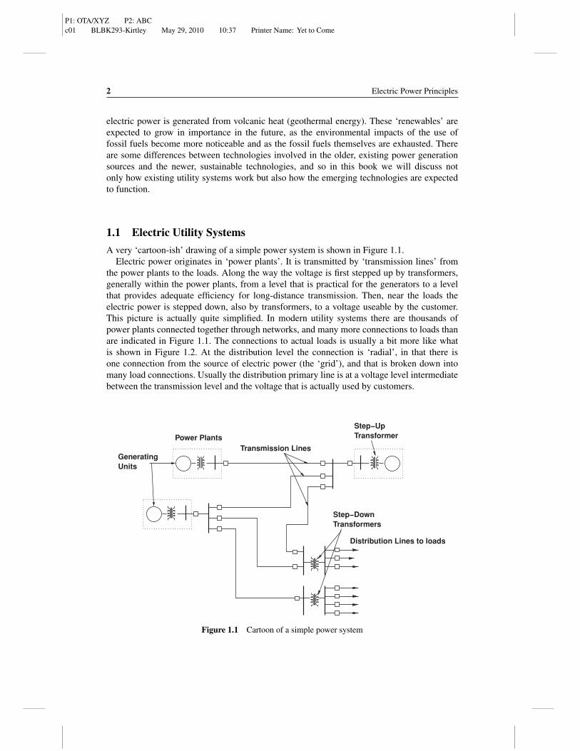
A very ‘cartoon-ish’ drawing of a simple power system is shown in Figure 1.1.Electric power originates in ‘power plants’. It is transmitted by ‘transmission lines’ from
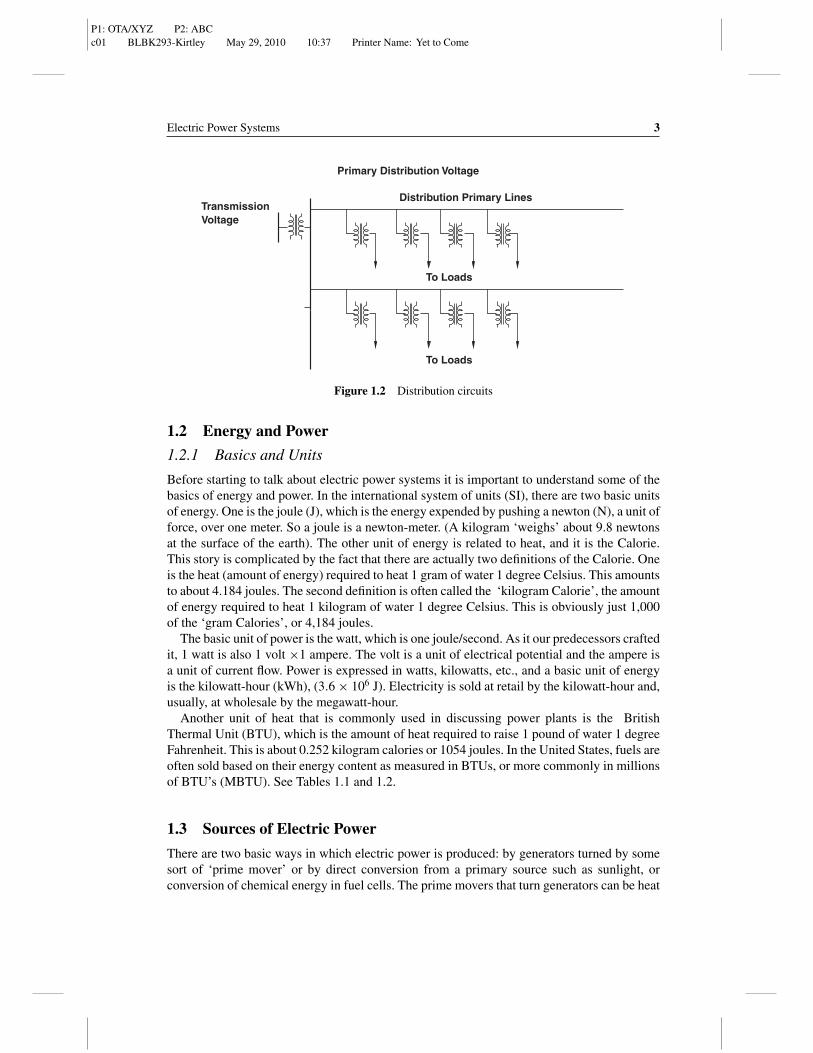
the power plants to the loads. Along the way the voltage is first stepped up by transformers,generally within the power plants, from a level that is practical for the generators to a levelthat provides adequate efficiency for long-distance transmission. Then, near the loads theelectric power is stepped down, also by transformers, to a voltage useable by the customer.This picture is actually quite simplified. In modern utility systems there are thousands ofpower plants connected together through networks, and many more connections to loads thanare indicated in Figure 1.1. The connections to actual loads is usually a bit more like whatis shown in Figure 1.2. At the distribution level the connection is ‘radial’, in that there isone connection from the source of electric power (the ‘grid’), and that is broken down intomany load connections. Usually the distribution primary line is at a voltage level intermediatebetween the transmission level and the voltage that is actually used by customers.
Transformers
Power PlantsTransmission Lines
Step−Up Transformer
GeneratingUnits
Distribution Lines to loads
Step−Down
Figure 1.1 Cartoon of a simple power system
P1: OTA/XYZ P2: ABCc01 BLBK293-Kirtley May 29, 2010 10:37 Printer Name: Yet to Come
Electric Power Systems 3
To Loads
TransmissionVoltage
Primary Distribution Voltage
Distribution Primary Lines
To Loads
Figure 1.2 Distribution circuits
1.2 Energy and Power
1.2.1 Basics and Units
Before starting to talk about electric power systems it is important to understand some of thebasics of energy and power. In the international system of units (SI), there are two basic unitsof energy. One is the joule (J), which is the energy expended by pushing a newton (N), a unit offorce, over one meter. So a joule is a newton-meter. (A kilogram ‘weighs’ about 9.8 newtonsat the surface of the earth). The other unit of energy is related to heat, and it is the Calorie.This story is complicated by the fact that there are actually two definitions of the Calorie. Oneis the heat (amount of energy) required to heat 1 gram of water 1 degree Celsius. This amountsto about 4.184 joules. The second definition is often called the ‘kilogram Calorie’, the amountof energy required to heat 1 kilogram of water 1 degree Celsius. This is obviously just 1,000of the ‘gram Calories’, or 4,184 joules.
The basic unit of power is the watt, which is one joule/second. As it our predecessors craftedit, 1 watt is also 1 volt ×1 ampere. The volt is a unit of electrical potential and the ampere isa unit of current flow. Power is expressed in watts, kilowatts, etc., and a basic unit of energyis the kilowatt-hour (kWh), (3.6 × 10⁶ J). Electricity is sold at retail by the kilowatt-hour and,usually, at wholesale by the megawatt-hour.
Another unit of heat that is commonly used in discussing power plants is the BritishThermal Unit (BTU), which is the amount of heat required to raise 1 pound of water 1 degreeFahrenheit. This is about 0.252 kilogram calories or 1054 joules. In the United States, fuels areoften sold based on their energy content as measured in BTUs, or more commonly in millionsof BTU’s (MBTU). See Tables 1.1 and 1.2.
1.3 Sources of Electric Power
There are two basic ways in which electric power is produced: by generators turned by somesort of ‘prime mover’ or by direct conversion from a primary source such as sunlight, orconversion of chemical energy in fuel cells. The prime movers that turn generators can be heat

P1: OTA/XYZ P2: ABCc01 BLBK293-Kirtley May 29, 2010 10:37 Printer Name: Yet to Come
4 Electric Power Principles
Table 1.1 Some of the unit symbols used in this book
Unit Unit of Symbol
Ampere current ABritish Thermal Unit heat energy BTUCoulomb charge CCalorie heat energy Caldegree Celsius temperature ◦CFarad capacitance FGauss flux density GHertz (cycles/second) frequency HzHenry inductance Hhour time hJoule energy JKelvin temperature Kkilogram mass kgmeter length mNewton force Nvolt electric potential Vvolt-ampere apparent power VAwatt power WWeber flux Wb
engines such as steam turbines, gas turbines, internal combustion engines burning diesel fuel,natural gas or (rarely) gasoline, or turbines that convert power directly from falling water orwind. Geothermal heat is sometimes used to power heat engines in places where that heat isaccessible (this is the major source of electric power in Iceland). Even sunlight has been usedas the power input to heat engines.
1.3.1 Heat Engines
Most power plant ‘prime movers’ are heat engines that burn a primary fuel such as coal ornatural gas and that use the energy released by combustion to produce mechanical power(generally turning a shaft) that is used to drive a generator to produce electrical power. We
Table 1.2 Multiplying prefixes used in this book
Prefix Symbol Multiple
tera T 1012
giga G 109
mega M 106
kilo k 103
centi c 10−2
milli m 10−3
micro µ 10−6
nano n 10−9

P1: OTA/XYZ P2: ABCc01 BLBK293-Kirtley May 29, 2010 10:37 Printer Name: Yet to Come
Electric Power Systems 5
Engine
Heat Input
Heat Rejected
Mechanical WorkHeat
Figure 1.3 Energy balance
will, in later chapters of this book describe how generators work. Heat engines can convertonly some of the heat energy that is input to the engines into mechanical work. The detailsof this are beyond our scope here, but as is shown in Figure 1.3, there will always be wasteheat associated with a heat engine. Heat engines take energy at a high temperature and rejectheat energy at a lower temperature. The difference between the heat input and rejected heatenergy is what is converted to mechanical power, and efficiency is the ratio of mechanicalpower output to heat power input.
There is a well known bound on efficiency of a heat engine, called the ‘Carnot efficiency’,and that is associated with the temperature of the input heat and the temperature of the rejectedheat. This is:
Wm < QhTh − T�
Th
where Qh is the input energy. Mechanical work is the difference between heat input andheat rejected, and the efficiency depends on the heat input temperature Th and heat rejectiontemperature T�. Practical heat engines do not approach this Carnot limit very closely, but thisexpression is a guide to heat engine efficiency: generally higher heat input temperatures andlower heat rejection temperatures lead to more efficient heat engines.
In discussing power plant efficiency, we often note that one kilowatt-hour is 3.6 MJ or3,414 BTU. The fuel energy input to a power plant to produce one kilowatt hour is referred toas its ‘heat rate’, and this is inversely related to its thermal efficiency. A power plant that has aheat rate of, say, 10,000 BTU/kWh would have a net thermal efficiency of η = 3414
10000 ≈ 0.3414.
1.3.2 Power Plants
Figure 1.4 shows a cartoon of a power plant that burns fossil fuels. The heat engine in thiscase is a steam turbine. Water is first compressed and pumped into a ‘boiler’, where a fireheats it into steam. The steam is expanded through a turbine which turns a generator. Theturbine exhaust is then fed to a ‘condenser’ where the waste heat is rejected. There are several

P1: OTA/XYZ P2: ABCc01 BLBK293-Kirtley May 29, 2010 10:37 Printer Name: Yet to Come
6 Electric Power Principles
Smokestack
Fuel Supply
Boiler
Steam Turbine
Generator
Transformer
CondenserCooling Water Supply
Feed Pump
Figure 1.4 Cartoon of a fossil fired power plant
different recipients of the rejected heat, depending on the situation: rivers, lakes, the ocean,purpose built cooling ponds or cooling towers are all used. Generated electricity is generatedat ‘medium’ voltage (‘medium voltage’ is generally taken to be between 1 kV and 100 kV,but power plant generators are generally limited to about 30 kV) and is usually stepped up to‘high’ (100 to 230 kV) or ‘extra high’ (230 to 800 kV) voltage for transmission.
While Figure 1.4 shows a coal-fired power plant, similar steam turbine-based power plantscan burn any of the fossil fuels, wood or even municipal garbage, and often such plants are builtin such a way that they can burn different fuels, based on which fuel is cheapest at a given time.
There are also power plants that employ gas turbines, as opposed to steam turbines, or evensome power plants that have gas turbine engines on the same shaft as steam turbine engines.The ‘simple cycle’ gas turbine engines are based on the same technology as jet engines thatpower aircraft (‘aero derivative’). ‘Binary cycle’ power plants use a gas turbine engine withthe exhaust gas rejecting heat to a steam cycle and can achieve higher efficiency than simplecycle gas- or steam- turbine engines, but with a higher level of complexity.
1.3.2.1 Environmental Impact of Burning Fossil Fuels
Fuels such as coal often have contaminants such as sulfur or mercury that have adverseenvironmental effects, and there has been, in recent years, substantial development of methodsto mitigate those effects.

P1: OTA/XYZ P2: ABCc01 BLBK293-Kirtley May 29, 2010 10:37 Printer Name: Yet to Come
Electric Power Systems 7
Table 1.3 Carbon analysis of hypothetical power plants
Fossil fuel carbon analysis Coal No. 6 Fuel Oil Natural Gas
Fraction carbon 0.807 0.857 0.750Fraction hydrogen 0.045 0.105 0.250HHV (BTU/kg) 30 870 40 263 50 780HHV (kJ/kg) 32 573 42 438 53 522kg CO2/kg fuel 2.959 3.142 2.750kg CO2/MBTU 95.9 78.0 54.2kg CO2/kWh (at 10 000 BTU/kWh) 0.959 0.780 0.542kg CO2/hour (at 1000 MW) 323 939 248 365 196 928kg CO2/hour 958 536 780 446 541 552
Mercury, for example, is toxic in surprisingly small quantities. When coal containing traceamounts of mercury is burned, the mercury is released in the effluent gas and/or ‘fly ash’(solids in the effluent gas) and then gets into some food chains such as fish. As big fish eatsmall fish the mercury is concentrated. As fish are generally fish eaters this process is repeateduntil fish near the top of the food chain are caught by the carnivores at the top of the foodchain (people). Sometimes toxic levels of mercury are present in those big fish.
Sulfur oxides and nitrogen oxides, the result of oxidation of nitrogen in the air, are the stuffof ‘acid rain’. There are different oxidation states of both nitrogen and sulfur, so that this typeof pollution is often referred to as ‘SOX and NOX ’. Not only do these chemicals produce acidrain, but they can (and do) react with hydrocarbons present in the air to form a visible hazethat is often referred to as ‘smog’. Methods of mitigating these pollutants have been developedbut are beyond our scope here.
Fossil fuels generally contain carbon and hydrogen (which is why they are called ‘hydro-carbons’, and the chief effluents of power plants are water vapor and carbon dioxide. Thelatter is a ‘greenhouse’ gas, and while it appears naturally in the atmosphere of the Earth,there are indications that man-made injections of carbon dioxide are raising the levels of CO2,with possible impacts on the earth’s heat balance (‘global warming’). For this reason, it seemsimportant to understand the carbon content of fuels.
Table 1.3 shows a simple analysis of carbon effluent for a 1,000 MW power plant assuminga ‘heat rate’ of 10,000 BTU/kWh. It should be noted that this heat rate, while it is within therange of numbers actually encountered, is not necessarily typical for any particular plant. Thefuels assumed in Table 1.3 are bituminous coal, heavy fuel oil (# 6 is what comes out nearthe bottom of the refinery distillation column) and natural gas. It should also be noted thatthese numbers are roughly correct, but that all of these fuels come with ranges of the variousquantities. For example, the energy content of bituminous coal varies between about 23 000and about 31,000 BTU/kg. Natural gas is primarily methane, which is 75% carbon and 25%hydrogen, but most sources of natural gas have some heavier components (ethane, propane,butane, etc.). Note that coal, which also can have varying fractions of carbon and hydrogen,has some non-combustible components (water, inorganic solids) as does fuel oil. The ‘higherheating value’ (HHV) for these fuels assumes that all of the heat released when the fuel isburned can be used, including the heat of vaporization of water that is produced when thehydrogen is combined with oxygen. This is often not the case, and the ‘lower heating value’is somewhat less.

P1: OTA/XYZ P2: ABCc01 BLBK293-Kirtley May 29, 2010 10:37 Printer Name: Yet to Come
8 Electric Power Principles
Cooling Water
Steam Turbine
Generator
Transformer
Containment Vessel
ReactorVessel
Core
Control Rods
Pressurizer
Steam Generator
Feed Pump
High VoltagePower to System
Figure 1.5 Cartoon of a nuclear power plant
Note that the amount of carbon dioxide produced when burning natural gas is substantiallysmaller, per unit of energy produced, than when coal or fuel oil is burned, and for that reasonnatural gas is sometimes thought of as a ‘cleaner’ fuel.
1.3.3 Nuclear Power Plants
Nuclear power plants employ the same thermodynamic cycle as most fossil fueled plants.Because of the relatively difficult environment for the materials that carry high-pressure water(it is radioactive in there), the high end temperature of a nuclear power plant cannot be as highas it can in fossil-fueled plants and so thermal efficiency tends to be a bit lower.
The reactor in a nuclear power plant generates heat through fission of heavy atoms intotwo (or more) lighter atoms. When an atom of uranium (U235), the isotope of uranium that iscapable of fission, splits, about 1/5 of an atomic mass unit (AMU) is converted to energy. Sincethe mass fraction of U235 in natural uranium is about 0.7%, were all of the fissile isotope to beconverted to energy, a fraction amounting to about 0.2
235 × 0.007 ≈ 6.1 × 10⁻⁶ of the naturaluranium would be converted to energy. That turns out to be quite a lot of energy, however,because E = MC2 = M × 9 × 10¹⁶ J/kg, or one kilogram of natural uranium would yieldabout 6.1 × 10−6 × 9 × 1016 ≈ 5.5 × 10¹¹J ≈ 1.53 × 10⁵kWh . If the plant operates with athermal efficiency of 33%, That would mean about 51,000 kWh/kg of natural uranium. Thiscompares with perhaps 3 or 4 kWh/kg for coal.
Virtually all commercial nuclear power plants are ‘light water’ moderated (LWR) and areeither of the ‘pressurized water’ or ‘boiling water’ type. Figure 1.5 is a cartoon sketch ofa pressurized water reactor type power plant. Moderation here means reducing the energyof the neutrons that are emitted from fissioning nuclei to the level that is best for initiatingfissioning of other nuclei. When a nucleus of uranium splits, it emits, among other things, afew ‘fast’ neutrons. These fast neutrons, while they can convert U238 to plutonium, are notvery effective at inducing fission in U235. Passing through the water that surrounds the fuel
P1: OTA/XYZ P2: ABCc01 BLBK293-Kirtley May 29, 2010 10:37 Printer Name: Yet to Come
Electric Power Systems 9
rods, the neutrons are slowed down, giving up energy and becoming ‘thermal neutrons’ (about0.025 eV), to the point where they are effective in inducing fission. In fact, since slowerneutrons are more effective in inducing fission, there is a negative reactivity coefficient withtemperature that tends to stabilize the chain reaction. Further control is afforded by the ‘controlrods’ that absorb neutrons. Dropping the rods fully into the reactor stops the chain reaction.The plutonium produced by fast neutrons interacting with U238 includes a fissile isotope thatis subsequently fissioned and this contributes more to the energy produced.
There is no carbon emitted by nuclear power plants in normal operation. The byproducts ofthe nuclear reaction, however, are really nasty stuff: lethally radioactive, hot and poisonous.Fortunately there is not a great deal of spent fuel produced and so it can be (and is) simplycontained. There is still much public debate about what to do with spent fuel and developmentof techniques for processing it or for stabilizing it so that it can be stored safely. Of particularinterest is the fact that the plutonium present in spent fuel can be used to make nuclearexplosives. The plutonium can be separated chemically, whereas fissile U235 cannot. This isboth good and bad news: good because plutonium is a useful fuel that can be mixed in withuranium and burned in reactors; bad because it facilitates fabrication of nuclear explosives,making securing spent fuel from potential terrorists or failed states very important, an addedexpense of the nuclear fuel cycle.
At the time of this writing (2009), there were 104 nuclear power plants in the United States,producing about 20% of the electric energy used in the country.
1.3.4 Hydroelectric Power
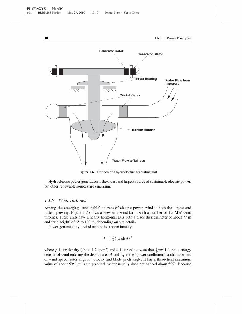
Hydroelectric power plants take advantage of falling water: under the influence of gravity,water descending through a pipe exerts force on a turbine wheel which, in turn, causes agenerator to rotate. Figure 1.6 shows a cartoon style cutaway of a hydroelectric unit (or‘waterwheel’). For hydrodynamic reasons these units tend to turn relatively slowly (severaltens to a few hundred r.p.m.), and can be physically quite large.
Power generated by a waterwheel unit is:
P = ρwater ghv̇ηt
where ρwater is mass density of water (1000kg/m3, g is acceleration due to gravity (about9.812m/s2), h is the ‘head’ or height the water falls, v̇ is volume flow of water and ηt isefficiency of the turbine system.
Hydroelectric power plants, even though they produce a relatively small fraction of to-tal generation, are very important because their reservoirs provide energy storage and theirgeneration can be modulated to supply power for variations in load over time. In fact, some‘pumped hydro’ plants have been built solely for storage. Two reservoirs are established atdifferent elevations. The hydroelectric generators are built so they can serve not only as gen-erators but also as pumps. When electric power is in surplus (or cheap), water is pumped‘uphill’ into the upper reservoir. Then, when electric power is in short supply (expensive),water is allowed to flow out of the upper reservoir to provide for extra generation. The lowerreservoir is often a river and the upper reservoir might be formed by hollowing out the topof a mountain.
P1: OTA/XYZ P2: ABCc01 BLBK293-Kirtley May 29, 2010 10:37 Printer Name: Yet to Come
10 Electric Power Principles
Water Flow to Tailrace
Water Flow fromPenstock
Generator StatorGenerator Rotor
Thrust Bearing
Wicket Gates
Turbine Runner
Figure 1.6 Cartoon of a hydroelectric generating unit
Hydroelectric power generation is the oldest and largest source of sustainable electric power,but other renewable sources are emerging.
1.3.5 Wind Turbines
Among the emerging ‘sustainable’ sources of electric power, wind is both the largest andfastest growing. Figure 1.7 shows a view of a wind farm, with a number of 1.5 MW windturbines. These units have a nearly horizontal axis with a blade disk diameter of about 77 mand ‘hub height’ of 65 to 100 m, depending on site details.
Power generated by a wind turbine is, approximately:
P = 1
2Cpρair Au3
where ρ is air density (about 1.2kg/m3) and u is air velocity, so that 12ρu2 is kinetic energy
density of wind entering the disk of area A and Cp is the ‘power coefficient’, a characteristicof wind speed, rotor angular velocity and blade pitch angle. It has a theoretical maximumvalue of about 59% but as a practical matter usually does not exceed about 50%. Because

P1: OTA/XYZ P2: ABCc01 BLBK293-Kirtley May 29, 2010 10:37 Printer Name: Yet to Come
Electric Power Systems 11
Figure 1.7 Turbine top view of the Klondike wind farm in Oregon, USA. Photo by Author
this coefficient is a function of wind and rotor tip speed (actually of the advance angle), windturbines work best if the rotational speed of the rotor is allowed to vary with wind speed.More will be said about this in the discussion the kinds of machines used for generators, butthe variable speed, constant frequency (VSCF) machines used for wind generators are amongthe most sophisticated of electric power generators. They start generating with wind speedsof about 3 m/s, generate power with a roughly cubic characteristic with respect to wind speeduntil they reach maximum generating capacity at 11–13 m/s, depending on details of the windturbine itself, and then, using pitch control, maintain constant rotational speed and generatedpower constant until the wind becomes too strong, at which point the turbine must be shutdown. This ‘cut out’ speed may be on the order of 30 m/s.
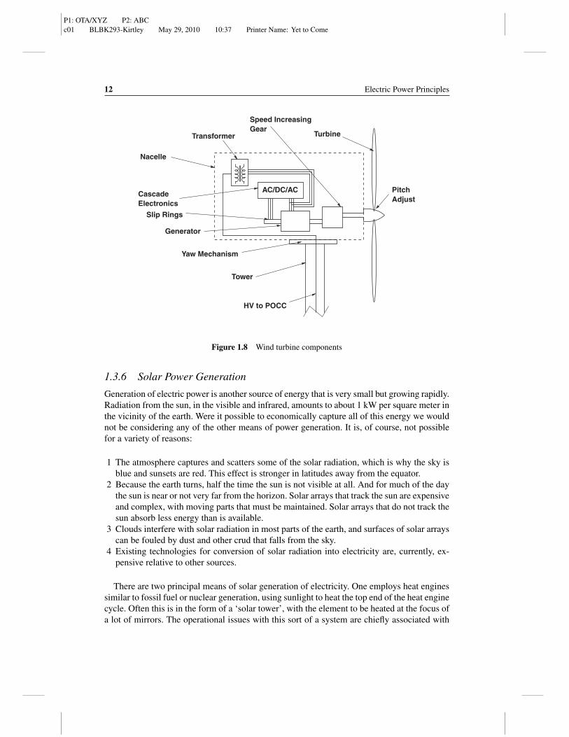
A cartoon showing the major elements of a wind turbine is shown in Figure 1.8. Turbineblades are mounted to a nose cone that contains pitch adjusters to control speed. The relativelylow turbine speeds are increased by a factor of perhaps 80 by a gear box, usually made up ofone planetary and two bull gear and pinion gear stages. The generator is often a doubly fedinduction generator: a wound rotor induction machine with a cascade of power electronicsto couple the rotor windings with the stator windings and local power system and to provideconstant frequency, variable speed capabilities.
The wind turbine is mounted on a tower that is usually implemented as simple steel tube,on the order of 65 to 100 m in height. The nacelle is mounted on a yaw mechanism to pointthe turbine at the wind. Both the yaw mechanism and the main turbine blades have brakingmechanisms (not shown in the figure). In some wind turbines there is a transformer in thenacelle to couple the low voltage of the generator to the medium voltage used to carry electricpower from the wind turbines to the point of common contact with the utility system (POCC).
P1: OTA/XYZ P2: ABCc01 BLBK293-Kirtley May 29, 2010 10:37 Printer Name: Yet to Come
12 Electric Power Principles
Slip Rings
AC/DC/AC
Turbine
PitchAdjust
Transformer
CascadeElectronics
Yaw Mechanism
Tower
HV to POCC
Generator
Nacelle
Speed IncreasingGear
Figure 1.8 Wind turbine components
1.3.6 Solar Power Generation
Generation of electric power is another source of energy that is very small but growing rapidly.Radiation from the sun, in the visible and infrared, amounts to about 1 kW per square meter inthe vicinity of the earth. Were it possible to economically capture all of this energy we wouldnot be considering any of the other means of power generation. It is, of course, not possiblefor a variety of reasons:
1 The atmosphere captures and scatters some of the solar radiation, which is why the sky isblue and sunsets are red. This effect is stronger in latitudes away from the equator.
2 Because the earth turns, half the time the sun is not visible at all. And for much of the daythe sun is near or not very far from the horizon. Solar arrays that track the sun are expensiveand complex, with moving parts that must be maintained. Solar arrays that do not track thesun absorb less energy than is available.
3 Clouds interfere with solar radiation in most parts of the earth, and surfaces of solar arrayscan be fouled by dust and other crud that falls from the sky.
4 Existing technologies for conversion of solar radiation into electricity are, currently, ex-pensive relative to other sources.
There are two principal means of solar generation of electricity. One employs heat enginessimilar to fossil fuel or nuclear generation, using sunlight to heat the top end of the heat enginecycle. Often this is in the form of a ‘solar tower’, with the element to be heated at the focus ofa lot of mirrors. The operational issues with this sort of a system are chiefly associated with
P1: OTA/XYZ P2: ABCc01 BLBK293-Kirtley May 29, 2010 10:37 Printer Name: Yet to Come
Electric Power Systems 13
−
Is
R
vd
+
−
I
V
+
Figure 1.9 Equivalent circuit model of a solar cell
tracking and focusing the sunlight on the top element. The method of operation of the powerplant is similar to that of any other heat engine.
The second means of generating electricity from sunlight employs photovoltaic cells. Theseare large area junction diodes that, when sunlight shines on them and splits electron/hole pairs,produce a current. The cost and efficiency of these cells are not very favorable at the presenttime, although for certain applications such as powering space stations (where solar energy ismore abundant than it is on the surface and where other fuels are very expensive) or poweringremote, low power services would otherwise be very expensive, they are the power source ofchoice. There has been and continues to be substantial development of solar cells and it is tobe anticipated that cost and performance will continue to improve.
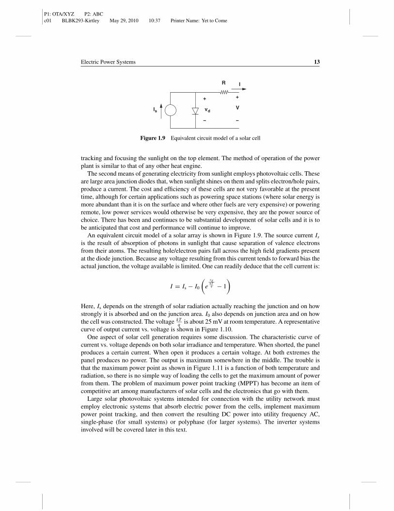
An equivalent circuit model of a solar array is shown in Figure 1.9. The source current Is
is the result of absorption of photons in sunlight that cause separation of valence electronsfrom their atoms. The resulting hole/electron pairs fall across the high field gradients presentat the diode junction. Because any voltage resulting from this current tends to forward bias theactual junction, the voltage available is limited. One can readily deduce that the cell current is:
I = Is − I0
(e
vdkTq − 1
)
Here, Is depends on the strength of solar radiation actually reaching the junction and on howstrongly it is absorbed and on the junction area. I0 also depends on junction area and on howthe cell was constructed. The voltage kT
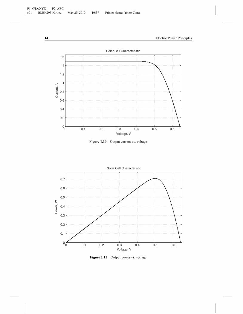
q is about 25 mV at room temperature. A representativecurve of output current vs. voltage is shown in Figure 1.10.
One aspect of solar cell generation requires some discussion. The characteristic curve ofcurrent vs. voltage depends on both solar irradiance and temperature. When shorted, the panelproduces a certain current. When open it produces a certain voltage. At both extremes thepanel produces no power. The output is maximum somewhere in the middle. The trouble isthat the maximum power point as shown in Figure 1.11 is a function of both temperature andradiation, so there is no simple way of loading the cells to get the maximum amount of powerfrom them. The problem of maximum power point tracking (MPPT) has become an item ofcompetitive art among manufacturers of solar cells and the electronics that go with them.
Large solar photovoltaic systems intended for connection with the utility network mustemploy electronic systems that absorb electric power from the cells, implement maximumpower point tracking, and then convert the resulting DC power into utility frequency AC,single-phase (for small systems) or polyphase (for larger systems). The inverter systemsinvolved will be covered later in this text.
P1: OTA/XYZ P2: ABCc01 BLBK293-Kirtley May 29, 2010 10:37 Printer Name: Yet to Come
14 Electric Power Principles
0 0.1 0.2 0.3 0.4 0.5 0.60
0.2
0.4
0.6
0.8
1
1.2
1.4
1.6
Solar Cell Characteristic
Cur
rent
, A
Voltage, V
Figure 1.10 Output current vs. voltage
0 0.1 0.2 0.3 0.4 0.5 0.60
0.1
0.2
0.3
0.4
0.5
0.6
0.7
Solar Cell Characteristic
Pow
er,
W
Voltage, V
Figure 1.11 Output power vs. voltage
P1: OTA/XYZ P2: ABCc01 BLBK293-Kirtley May 29, 2010 10:37 Printer Name: Yet to Come
Electric Power Systems 15
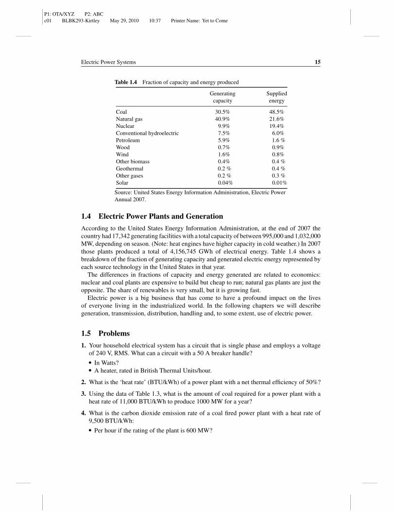
Table 1.4 Fraction of capacity and energy produced
Generating Suppliedcapacity energy
Coal 30.5% 48.5%Natural gas 40.9% 21.6%Nuclear 9.9% 19.4%Conventional hydroelectric 7.5% 6.0%Petroleum 5.9% 1.6 %Wood 0.7% 0.9%Wind 1.6% 0.8%Other biomass 0.4% 0.4 %Geothermal 0.2 % 0.4 %Other gases 0.2 % 0.3 %Solar 0.04% 0.01%
Source: United States Energy Information Administration, Electric PowerAnnual 2007.
1.4 Electric Power Plants and Generation
According to the United States Energy Information Administration, at the end of 2007 thecountry had 17,342 generating facilities with a total capacity of between 995,000 and 1,032,000MW, depending on season. (Note: heat engines have higher capacity in cold weather.) In 2007those plants produced a total of 4,156,745 GWh of electrical energy. Table 1.4 shows abreakdown of the fraction of generating capacity and generated electric energy represented byeach source technology in the United States in that year.
The differences in fractions of capacity and energy generated are related to economics:nuclear and coal plants are expensive to build but cheap to run; natural gas plants are just theopposite. The share of renewables is very small, but it is growing fast.
Electric power is a big business that has come to have a profound impact on the livesof everyone living in the industrialized world. In the following chapters we will describegeneration, transmission, distribution, handling and, to some extent, use of electric power.
1.5 Problems
1. Your household electrical system has a circuit that is single phase and employs a voltageof 240 V, RMS. What can a circuit with a 50 A breaker handle?� In Watts?� A heater, rated in British Thermal Units/hour.
2. What is the ‘heat rate’ (BTU/kWh) of a power plant with a net thermal efficiency of 50%?
3. Using the data of Table 1.3, what is the amount of coal required for a power plant with aheat rate of 11,000 BTU/kWh to produce 1000 MW for a year?
4. What is the carbon dioxide emission rate of a coal fired power plant with a heat rate of9,500 BTU/kWh:� Per hour if the rating of the plant is 600 MW?

P1: OTA/XYZ P2: ABCc01 BLBK293-Kirtley May 29, 2010 10:37 Printer Name: Yet to Come
16 Electric Power Principles
� Per kWh?
Use the data contained in Table 1.3.
5. What is the carbon dioxide emission rate of a natural gas fired power plant with a thermalefficiency of 53%?� Per hour if the rating of the plant is 600 MW?� Per kWh?
Use the data contained in Table 1.3.
6. A nuclear power plant ‘burns’ Uranium enriched to about 4% U235, the fissile isotope. Ifthis plant achieves a ‘burnup’ of 50% (that is, it converts half of the fissile component ofthe fuel), how much enriched uranium is required for the plant to make 1000 MW for ayear? Assume a heat rate of 12,000 BTU/kWh.
7. Assume the density of air to be 1.2kg/m3. What diameter wind turbine is required to capture1.5 MW at a wind speed of 10 m/s if the turbine coefficient of performance is 40%?
8. What is the water volume flow rate for a 100 MW water turbine operating with a ‘head’ of20 meters, assuming an efficiency of the turbine and generator of 80%? (Water has a massdensity of 1000 kg/m3).