electric power system basics - dell optiplex 755lnx01.ee.polyu.edu.hk/~eewlchan/ee1d01/ebook/pages...
TRANSCRIPT

ELECTRIC POWERSYSTEM BASICSFor the Nonelectrical Professional
Steven W. Blume
WILEY-INTERSCIENCEA JOHN WILEY & SONS, INC., PUBLICATION
IEEE PRESS
Mohamed E. El-Hawary, Series Editor
ffirs.qxd 10/10/2007 4:46 PM Page iii

Electric Power System Basics. By Steven W. Blume 1Copyright © 2007 the Institute of Electrical and Electronics Engineers, Inc.
1SYSTEM OVERVIEW,
TERMINOLOGY, ANDBASIC CONCEPTS
CHAPTER OBJECTIVES
�✓ Discuss the history of electricity
�✓ Present a basic overview of today’s electric power system
�✓ Discuss general terminology and basic concepts used in the powerindustry
�✓ Explain the key terms voltage, current, power, and energy
�✓ Discuss the nature of electricity and terminology relationships
�✓ Describe the three types of consumption loads and theircharacteristics
HISTORY OF ELECTRIC POWER
Benjamin Franklin is known for his discovery of electricity. Born in 1706,he began studying electricity in the early 1750s. His observations, includinghis kite experiment, verified the nature of electricity. He knew that lightningwas very powerful and dangerous. The famous 1752 kite experiment fea-tured a pointed metal piece on the top of the kite and a metal key at the base
c01.qxd 8/24/2007 1:36 PM Page 1

end of the kite string. The string went through the key and attached to a Ley-den jar. (A Leyden jar consists of two metal conductors separated by an in-sulator.) He held the string with a short section of dry silk as insulation fromthe lightning energy. He then flew the kite in a thunderstorm. He first no-ticed that some loose strands of the hemp string stood erect, avoiding oneanother. (Hemp is a perennial American plant used in rope making by theIndians.) He proceeded to touch the key with his knuckle and received asmall electrical shock.
Between 1750 and 1850 there were many great discoveries in the princi-ples of electricity and magnetism by Volta, Coulomb, Gauss, Henry, Fara-day, and others. It was found that electric current produces a magnetic fieldand that a moving magnetic field produces electricity in a wire. This led tomany inventions such as the battery (1800), generator (1831), electric motor(1831), telegraph (1837), and telephone (1876), plus many other intriguinginventions.
In 1879, Thomas Edison invented a more efficient lightbulb, similar tothose in use today. In 1882, he placed into operation the historic Pearl Streetsteam–electric plant and the first direct current (dc) distribution system inNew York City, powering over 10,000 electric lightbulbs. By the late 1880s,power demand for electric motors required 24-hour service and dramaticallyraised electricity demand for transportation and other industry needs. By theend of the 1880s, small, centralized areas of electrical power distributionwere sprinkled across U.S. cities. Each distribution center was limited to aservice range of a few blocks because of the inefficiencies of transmittingdirect current. Voltage could not be increased or decreased using direct cur-rent systems, and a way to to transport power longer distances was needed.
To solve the problem of transporting electrical power over long dis-tances, George Westinghouse developed a device called the “transformer.”The transformer allowed electrical energy to be transported over long dis-tances efficiently. This made it possible to supply electric power to homesand businesses located far from the electric generating plants. The applica-tion of transformers required the distribution system to be of the alternatingcurrent (ac) type as opposed to direct current (dc) type.
The development of the Niagara Falls hydroelectric power plant in 1896initiated the practice of placing electric power generating plants far fromconsumption areas. The Niagara plant provided electricity to Buffalo, NewYork, more than 20 miles away. With the Niagara plant, Westinghouse con-vincingly demonstrated the superiority of transporting electric power overlong distances using alternating current (ac). Niagara was the first largepower system to supply multiple large consumers with only one power line.
2 SYSTEM OVERVIEW, TERMINOLOGY, AND BASIC CONCEPTS
c01.qxd 8/24/2007 1:36 PM Page 2
Since the early 1900s alternating current power systems began appearingthroughout the United States. These power systems became interconnectedto form what we know today as the three major power grids in the UnitedStates and Canada. The remainder of this chapter discusses the fundamentalterms used in today’s electric power systems based on this history.
SYSTEM OVERVIEW
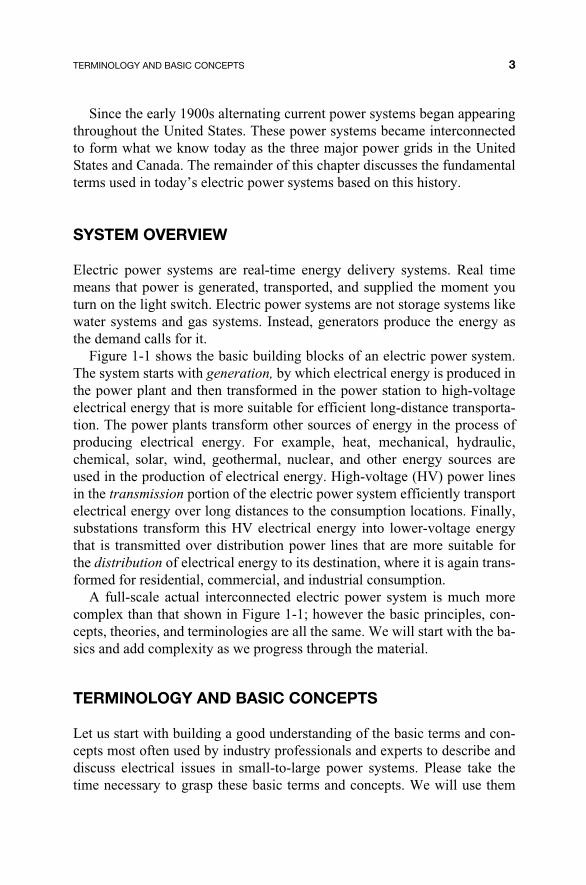
Electric power systems are real-time energy delivery systems. Real timemeans that power is generated, transported, and supplied the moment youturn on the light switch. Electric power systems are not storage systems likewater systems and gas systems. Instead, generators produce the energy asthe demand calls for it.
Figure 1-1 shows the basic building blocks of an electric power system.The system starts with generation, by which electrical energy is produced inthe power plant and then transformed in the power station to high-voltageelectrical energy that is more suitable for efficient long-distance transporta-tion. The power plants transform other sources of energy in the process ofproducing electrical energy. For example, heat, mechanical, hydraulic,chemical, solar, wind, geothermal, nuclear, and other energy sources areused in the production of electrical energy. High-voltage (HV) power linesin the transmission portion of the electric power system efficiently transportelectrical energy over long distances to the consumption locations. Finally,substations transform this HV electrical energy into lower-voltage energythat is transmitted over distribution power lines that are more suitable forthe distribution of electrical energy to its destination, where it is again trans-formed for residential, commercial, and industrial consumption.
A full-scale actual interconnected electric power system is much morecomplex than that shown in Figure 1-1; however the basic principles, con-cepts, theories, and terminologies are all the same. We will start with the ba-sics and add complexity as we progress through the material.
TERMINOLOGY AND BASIC CONCEPTS
Let us start with building a good understanding of the basic terms and con-cepts most often used by industry professionals and experts to describe anddiscuss electrical issues in small-to-large power systems. Please take thetime necessary to grasp these basic terms and concepts. We will use them
TERMINOLOGY AND BASIC CONCEPTS 3
c01.qxd 8/24/2007 1:36 PM Page 3

4
Fig
ure
1-1.
Sys
tem
ove
rvie
w.
Hig
h-V
olta
ge P
ower
Lin
esIn
dust
rial
Con
sum
er
Distribution Power Lines
c01.qxd 8/24/2007 1:36 PM Page 4
throughout this book to build a complete working knowledge of electricalpower systems.
Voltage
The first term or concept to understand is voltage. Voltage is the potentialenergy source in an electrical circuit that makes things happen. It is some-times called Electromotive Force or EMF. The basic unit (measurement) ofelectromotive force (EMF) is the volt. The volt was named in honor of Al-lessandro Giuseppe Antonio Anastasio Volta (1745–1827), the Italianphysicist who also invented the battery. Electrical voltage is identified bythe symbol “e” or “E.” (Some references use symbols “v” or “V.”
Voltage is the electric power system’s potential energy source. Voltagedoes nothing by itself but has the potential to do work. Voltage is a push ora force. Voltage always appears between two points.
Normally, voltage is either constant (i.e., direct) or alternating. Electricpower systems are based on alternating voltage applications from low-volt-age 120 volt residential systems to ultra high voltage 765,000 volt transmis-sion systems. There are lower and higher voltage applications involved inelectric power systems, but this is the range commonly used to cover gener-ation through distribution and consumption.
In water systems, voltage corresponds to the pressure that pushes waterthrough a pipe. The pressure is present even though no water is flowing.
Current
Current is the flow of electrons in a conductor (wire). Electrons are pushedand pulled by voltage through an electrical circuit or closed-loop path. Theelectrons flowing in a conductor always return to their voltage source. Cur-rent is measured in amperes, usually called amps. (One amp is equal to 628× 1016 electrons flowing in the conductor per second.) The number of elec-trons never decreases in a loop or circuit. The flow of electrons in a conduc-tor produces heat due to the conductor’s resistance (i.e., friction).
Voltage always tries to push or pull current. Therefore, when a completecircuit or closed-loop path is provided, voltage will cause current to flow. Theresistance in the circuit will reduce the amount of current flow and will causeheat to be provided. The potential energy of the voltage source is thereby con-verted into kinetic energy as the electrons flow. The kinetic energy is then uti-lized by the load (i.e., consumption device) and converted into useful work.
Current flow in a conductor is similar to ping-pong balls lined up in atube. Referring to Figure 1-2, pressure on one end of the tube (i.e., voltage)
TERMINOLOGY AND BASIC CONCEPTS 5
c01.qxd 8/24/2007 1:36 PM Page 5

pushes the balls through the tube. The pressure source (i.e., battery) collectsthe balls exiting the tube and returns them to the tube in a circulating man-ner (closed-loop path). The number of balls traveling through the tube persecond is analogous to current. This movement of electrons in a specifieddirection is called current. Electrical current is identified by the symbol “i”or “I.”
Hole Flow Versus Electron Flow
Electron flow occurs when the electron leaves the atom and moves towardthe positive side of the voltage source, leaving a hole behind. The holes leftbehind can be thought of as a current moving toward the negative side of thevoltage source. Therefore, as electrons flow in a circuit in one direction,holes are created in the same circuit that flow in the opposite direction. Cur-rent is defined as either electron flow or hole flow. The standard conventionused in electric circuits is hole flow! One reason for this is that the conceptof positive (+) and negative (–) terminals on a battery or voltage source wasestablished long before the electron was discovered. The early experimentssimply defined current flow as being from positive to negative, withoutreally knowing what was actually moving.
One important phenomenon of current flowing in a wire that we will dis-cuss in more detail later is the fact that a current flowing in a conductor pro-duces a magnetic field. (See Figure 1-3.) This is a physical law, similar togravity being a physical law. For now, just keep in mind that when electronsare pushed or pulled through a wire by voltage, a magnetic field is producedautomatically around the wire. Note: Figure 1-3 is a diagram that corre-sponds to the direction of conventional or hole flow current according to the“right-hand rule.”
6 SYSTEM OVERVIEW, TERMINOLOGY, AND BASIC CONCEPTS
Figure 1-2. Current flow.
c01.qxd 8/24/2007 1:36 PM Page 6

Power
The basic unit (measurement) of power is the watt (W), named after JamesWatt (1736–1819), who also invented the steam engine. Voltage by itselfdoes not do any real work. Current by itself does not do any real work.However, voltage and current together can produce real work. The productof voltage times current is power. Power is used to produce real work.
For example, electrical power can be used to create heat, spin motors, lightlamps, and so on. The fact that power is part voltage and part current means thatpower equals zero if either voltage or current are zero. Voltage might appear ata wall outlet in your home and a toaster might be plugged into the outlet, butuntil someone turns on the toaster, no current flows, and, hence, no power oc-curs until the switch is turned on and current is flowing through the wires.
Energy
Electrical energy is the product of electrical power and time. The amount oftime a load is on (i.e., current is flowing) times the amount of power used bythe load (i.e., watts) is energy. The measurement for electrical energy iswatt-hours (Wh). The more common units of energy in electric power sys-
TERMINOLOGY AND BASIC CONCEPTS 7
Figure 1-3. Current and magnetic field.
Current flowing in a wire
Magnetic field
Magnetic field
c01.qxd 8/24/2007 1:36 PM Page 7

tems are kilowatt-hours (kWh, meaning 1,000 watt-hours) for residentialapplications and megawatt-hours (MWh, meaning 1,000,000 watt-hours)for large industrial applications or the power companies themselves.
dc Voltage and Current
Direct current (dc) is the flow of electrons in a circuit that is always in thesame direction. Direct current (i.e., one-direction current) occurs when thevoltage is kept constant, as shown in Figure 1-4. A battery, for example,produces dc current when connected to a circuit. The electrons leave thenegative terminal of the battery and move through the circuit toward thepositive terminal of the battery.
ac Voltage and Current
When the terminals of the potential energy source (i.e., voltage) alternatebetween positive and negative, the current flowing in the electrical circuitlikewise alternates between positive and negative. Thus, alternating current(ac) occurs when the voltage source alternates.
Figure 1-5 shows the voltage increasing from zero to a positive peak val-ue, then decreasing through zero to a negative value, and back through zeroagain, completing one cycle. In mathematical terms, this describes a sinewave. The sine wave can repeat many times in a second, minute, hour, orday. The length of time it takes to complete one cycle in a second is calledthe period of the cycle.
Frequency
Frequency is the term used to describe the number of cycles in a second.The number of cycles per second is also called hertz, named after Heinrich
8 SYSTEM OVERVIEW, TERMINOLOGY, AND BASIC CONCEPTS
Figure 1-4. Direct current (dc voltage).
Time
Voltage is constant over time
Vol
tage
c01.qxd 8/24/2007 1:36 PM Page 8

Hertz (1857–1894), a German physicist. Note: direct current (dc) has no fre-quency; therefore, frequency is a term used only for ac circuits.
For electric power systems in the United States, the standard frequency is60 cycles/second or 60 hertz. The European countries have adopted 50 hertzas the standard frequency. Countries outside the United States and Europeuse 50 and/or 60 hertz. (Note: at one time the United States had 25, 50, and60 hertz systems. These were later standardized to 60 hertz.)
Comparing ac and dc Voltage and Current
Electrical loads, such as lightbulbs, toasters, and hot water heaters, can beserved by either ac or dc voltage and current. However, dc voltage sourcescontinuously supply heat in the load, whereas ac voltage sources cause heatto increase and decrease during the positive part of the cycle, then increaseand decrease again in the negative part of the cycle. In ac circuits, there areactually moments of time when the voltage and current are zero and no ad-ditional heating occurs.
It is important to note that there is an equivalent ac voltage and current thatwill produce the same heating effect in an electrical load as if it were a dc volt-age and current. The equivalent voltages and currents are referred to as theroot mean squared values, or rms values. The reason this concept is importantis that all electric power systems are rated in rms voltages and currents.
For example, the 120 Vac wall outlet is actually the rms value. Theoreti-cally, one could plug a 120 Vac toaster into a 120 Vdc battery source and
TERMINOLOGY AND BASIC CONCEPTS 9
Figure 1-5. Alternating current (ac voltage).
Negative voltage
Positive voltage
Peak positive
Peak Negative
1 Period
Time
0
c01.qxd 8/24/2007 1:36 PM Page 9

cook the toast in the same amount of time. The ac rms value has the sameheating capability as a dc value.
Optional Supplementary Reading
Appendix A explains how rms is derived.
The Three Types of Electrical Loads
Devices that are connected to the power system are referred to as electricalloads. Toasters, refrigerators, bug zappers, and so on are considered electri-cal loads. There are three types of electrical loads. They vary according totheir leading or lagging time relationship between voltage and current.
The three load types are resistive, inductive, and capacitive. Each typehas specific characteristics that make them unique. Understanding the dif-ferences between these load types will help explain how power systems canoperate efficiently. Power system engineers, system operators, maintenancepersonnel, and others try to maximize system efficiency on a continuous ba-sis by having a good understanding of the three types of loads. They under-stand how having them work together can minimize system losses, provideadditional equipment capacity, and maximize system reliability.
The three different types of load are summarized below. The standardunits of measurement are in parentheses and their symbols and abbrevia-tions follow.
Resistive Load (Figure 1-6)
The resistance in a wire (i.e., conductor) causes friction and reduces theamount of current flow if the voltage remains constant. Byproducts of thiselectrical friction are heat and light. The units (measurement) of resistanceare referred to as ohms. The units of electrical power associated with resis-tive load are watts. Lightbulbs, toasters, electric hot water heaters, and so onare resistive loads.
10 SYSTEM OVERVIEW, TERMINOLOGY, AND BASIC CONCEPTS
Figure 1-6. Resistive loads.
R
Resistive(ohms)
c01.qxd 8/24/2007 1:36 PM Page 10

Inductive Load (Figure 1-7)
Inductive loads require a magnetic field to operate. All electrical loads thathave a coil of wire to produce the magnetic field are called inductive loads.Examples of inductive loads are hair dryers, fans, blenders, vacuum cleaners,and many other motorized devices. In essence, all motors are inductive loads.The unique difference between inductive loads and other load types is that thecurrent in an inductive load lags the applied voltage. Inductive loads taketime to develop their magnetic field when the voltage is applied, so the cur-rent is delayed. The units (measurement) of inductance are called henrys.
Regarding electrical motors, a load placed on a spinning shaft to performa work function draws what is referred to as real power (i.e., watts) from theelectrical energy source. In addition to real power, what is referred to as re-active power is also drawn from the electrical energy source to produce themagnetic fields in the motor. The total power consumed by the motor is,therefore, the sum of both real and reactive power. The units of electricalpower associated with reactive power are called positive VARs. (Theacronym VAR stands for volts-amps-reactive.)
Capacitive Load (Figure 1-8)
A capacitor is a device made of two metal conductors separated by an insu-lator called a dielectric (i.e., air, paper, glass, and other nonconductive ma-terials). These dielectric materials become charged when voltage is appliedto the attached conductors. Capacitors can remain charged long after the
LAST #1 HEAD 11
Figure 1-7. Inductive loads.
L
Inductive(henrys)
Figure 1-8. Capacitive loads.
CCapacitive(farads)
c01.qxd 8/24/2007 1:36 PM Page 11

voltage source has been removed. Examples of capacitor loads are TV pic-ture tubes, long extension cords, and components used in electronic devices.
Opposite to inductors, the current associated with capacitors leads (in-stead of lags) the voltage because of the time it takes for the dielectric mate-rial to charge up to full voltage from the charging current. Therefore, it issaid that the current in a capacitor leads the voltage. The units (measure-ment) of capacitance are called farads.
Similar to inductors, the power associated with capacitors is also calledreactive power, but has the opposite polarity. Thus, inductors have positiveVARs and capacitors have negative VARs. Note, the negative VARs of in-ductors can be cancelled by the positive VARs of capacitors, to leading anet zero reactive power requirement. How capacitors cancel out inductors inelectrical circuits and improve system efficiency will be discussed later.
As a general rule, capacitive loads are not items that people purchase atthe store in massive quantities like they do resistive and inductive loads. Forthat reason, power companies must install capacitors on a regular basis tomaintain a reactive power balance with the inductive demand.
12 SYSTEM OVERVIEW, TERMINOLOGY, AND BASIC CONCEPTS
c01.qxd 8/24/2007 1:36 PM Page 12

Electric Power System Basics. By Steven W. Blume 13Copyright © 2007 the Institute of Electrical and Electronics Engineers, Inc.
2
GENERATION
CHAPTER OBJECTIVES
�✓ Describe how voltage is produced in a conductor when in thepresence of a changing magnetic field
�✓ Explain how three coils of wire in the presence of a changingmagnetic field produce three-phase voltage
�✓ Describe how current flowing through a wire produces a magneticfield
�✓ Discuss how generator rotors provide the magnetic field for thegeneration of electricity
�✓ Describe the three main components of a generator
�✓ Explain what is meant by real-time generation
�✓ Discuss the two different ways to connect three generator windingssymmetrically
�✓ Discuss the different types of generation plants (i.e., steam, nuclear,wind, etc.)
�✓ Describe the different power plant prime-mover types
c02.qxd 8/24/2007 1:37 PM Page 13

�✓ Discuss the conversion of mechanical energy to electrical energy
�✓ Discuss how the various energy resources are converted intoelectrical energy
�✓ Describe the environmental considerations for the different powerplant types
ac VOLTAGE GENERATION
There are basically two physical laws that describe how electric power sys-tems work. (Gravity is an example of a physical law.) One law has to dowith generating a voltage from a changing magnetic field and the other hasto do with a current flowing through a wire creating a magnetic field. Bothphysical laws are used throughout the entire electric power system fromgeneration through transmission, distribution, and consumption. The combi-nation of these two laws makes our electric power systems work. Under-standing these two physical laws will enable the reader to fully understandand appreciate how electric power systems work.
Physical Law #1
ac voltage is generated in electric power systems by a very fundamentalphysical law called Faraday’s Law. Faraday’s Law represents the phe-nomena behind how electric motors turn and how electric generators pro-duce electricity. Faraday’s Law is the foundation for electric power sys-tems.
Faraday’s Law states, “A voltage is produced on any conductor in achanging magnetic field.” It may be difficult to grasp the full meaning ofthat statement at first. It is, however, easier to understand the meaning andsignificance of this statement through graphs, pictures, and animations.
In essence, this statement is saying that if one takes a coil of wire andputs it next to a moving or rotating magnet, a measurable voltage will beproduced in that coil. Generators, for example, use a spinning magnet (i.e.,rotor) next to a coil of wire to produce voltage. This voltage is then distrib-uted throughout the electric power system.
We will now study how a generator works. Keep in mind that virtuallyall generators in service today have coils of wire mounted on stationaryhousings, called stators, where voltage is produced due to the magneticfield provided on the spinning rotor. The rotor is sometimes called thefield because it is responsible for the magnetic field portion of the genera-
14 GENERATION
c02.qxd 8/24/2007 1:37 PM Page 14

tor. The rotor’s strong magnetic field passes the stator windings (coils),thus producing or generating an alternating voltage (ac) that is based onFaraday’s Law. This principle will be shown and described in the follow-ing sections.
The amplitude of the generator’s output voltage can be changed bychanging the strength of rotor’s magnetic field. Thus, the generator’s outputvoltage can be lowered by reducing the rotor’s magnetic field strength. Themeans by which the magnetic field in the rotor is actually changed will bediscussed later in this book when Physical Law #2 is discussed.
Single-Phase ac Voltage Generation
Placing a coil of wire (i.e., conductor) in the presence of a moving magneticfield produces a voltage, as discovered by Faraday. This principle is graphi-cally presented in Figure 2-1. While reviewing the drawing, note that chang-ing the rotor’s speed changes the frequency of the sine wave. Also recog-nize the fact that increasing the number of turns (loops) of conductor or wirein the coil increases the resulting output voltage.
Three-Phase ac Voltage Generation
When three coils are placed in the presence of a changing magnetic field,three voltages are produced. When the coils are spaced 120 degrees apart ina 360 degree circle, three-phase ac voltage is produced. As shown in Figure2-2, three-phase generation can be viewed as three separate single-phasegenerators, each of which are displaced by 120 degrees.
THE THREE-PHASE ac GENERATOR
Large and small generators that are connected to the power system havethree basic components: stator, rotor, and exciter. This section discussesthese three basic components.
The Stator
A three-phase ac generator has three single-phase windings. These threewindings are mounted on the stationary part of the generator, called thestator. The windings are physically spaced so that the changing magnet-ic field present on each winding is 120° out of phase with the other wind-
ac VOLTAGE GENERATION 15
c02.qxd 8/24/2007 1:37 PM Page 15

ings. A simplified drawing of a three-phase generator is shown in Figure2-3.
The Rotor
The rotor is the center component that when turned moves the magneticfield. A rotor could have a permanent magnet or an electromagnet and stillfunction as a generator. Large power plant generators use electromagnets so
16 GENERATION
Figure 2-1. Magnetic sine wave.
c02.qxd 8/24/2007 1:37 PM Page 16

that the magnetic field can be varied. Varying the magnetic field strength ofthe rotor enables generation control systems to adjust the output voltage ac-cording to load demand and system losses. A drawing of an electromagnetis shown in Figure 2-4.
The operation of electromagnets is described by Physical Law #2.
Ampere’s and Lenz’s Law (Physical Law #2)
The second basic physical law that explains how electric power systemswork is the fact that current flowing in a wire produces a magnetic field.Ampere’s and Lenz’s law states that “a current flowing in a wire produces amagnetic field around the wire.” This law describes the relationship be-
THE THREE-PHASE AC GENERATOR 17
Figure 2-2. Three-phase voltage production.
Figure 2-3. Three-phase generator—stator.
c02.qxd 8/24/2007 1:37 PM Page 17

tween the production of magnetic fields and electric current flowing in awire. In essence, when a current flows through a wire, a magnetic field sur-rounds the wire.
Electromagnets
Applying a voltage (e.g., battery) to a coil of wire produces a magnetic field.The coil’s magnetic field will have a north and a south pole as shown in Fig-ure 2-4. Increasing the voltage or the number of turns in the winding in-creases the magnetic field. Conversely, decreasing the voltage or number ofturns in the winding decreases the magnetic field. Slip rings are electricalcontacts that are used to connect the stationary battery to the rotating rotor,as shown in Figure 2-4 and Figure 2-5.
The Exciter
The voltage source for the rotor, which eventually creates the rotor’s mag-netic field, is called the exciter, and the coil on the rotor is called the field.Figure 2-5 shows the three main components of a three-phase ac generator:the stator, rotor, and exciter.
Most generators use slip rings to complete the circuit between the sta-tionary exciter voltage source and the rotating coil on the rotor where theelectromagnet produces the north and south poles.
Note: Adding load to a generator’s stator windings reduces rotor speedbecause of the repelling forces between the stator’s magnetic field, and the
18 GENERATION
Figure 2-4. Electromagnet and slip rings.
c02.qxd 8/24/2007 1:37 PM Page 18

rotor’s magnetic field since both windings have electrical current flowingthrough them. Conversely, removing load from a generator increases rotorspeed. Therefore, the mechanical energy of the prime mover that is respon-sible for spinning the rotor must be adjusted to maintain rotor speed or fre-quency under varying load conditions.
Rotor Poles
Increasing the number of magnetic poles on the rotor enables rotor speeds tobe slower and still maintain the same electrical output frequency. Genera-tors that require slower rotor speeds to operate properly use multiple-polerotors. For example, hydropower plants use generators with multiple-polerotors because the prime mover (i.e., water) is very dense and harder to con-trol than light-weight steam.
The relationship between the number of poles on the rotor and the speedof the shaft is determined using the following mathematical formula:
Revolutions per minute =
Figure 2-6 shows the concept of multiple poles in a generator rotor. Sincethese poles are derived from electromagnets, having multiple windings on arotor can provide multiple poles.
7200��Number of poles
THE THREE-PHASE AC GENERATOR 19
Figure 2-5. Three-phase voltage generator components.
WindingsStator
Slip Rings
Excitor
Variabledc Voltage
Rot
or
c02.qxd 8/24/2007 1:37 PM Page 19

Example 1: A two pole rotor would turn at 3600 rpm for 60 hertz.
Example 2: Some of the generators at Hoover Dam near Las Vegas, Nevada,use 40-pole rotors. Therefore, the rotor speed is 180 rpm or three revolutionsper second, yet the electrical frequency is 60 cycles/second (or 60 Hz). Onecan actually see the shaft turning at this relatively slow rotational speed.
REAL-TIME GENERATION
Power plants produce electrical energy on a real-time basis. Electric powersystems do not store energy such as most gas or water systems do. For ex-ample, when a toaster is switched on and drawing electrical energy from thesystem, the associated generating plants immediately see this as new loadand slightly slow down. As more and more load (i.e., toasters, lights, mo-tors, etc.) are switched on, generation output and prime mover rotationalshaft energy must be increased to balance the load demand on the system.Unlike water utility systems that store water in tanks located up high on hillsor tall structures to serve real-time demand, electric power systems mustcontrol generation to balance load on demand. Water is pumped into thetank when the water level in the tank is low, allowing the pumps to turn offduring low and high demand periods. Electrical generation always produceselectricity on an “as needed” basis. Note: some generation units can be tak-en off-line during light load conditions, but there must always be enoughgeneration online to maintain frequency during light and heavy load condi-tions.
There are electrical energy storage systems such as batteries, but electric-ity found in interconnected ac power systems is in a real-time energy supplysystem, not an energy storage system.
20 GENERATION
Figure 2-6. Rotor poles.
Two-pole Four-pole
c02.qxd 8/24/2007 1:37 PM Page 20

GENERATOR CONNECTIONS
There are two ways to connect three windings that have a total of six leads(the ends of the winding wires) symmetrically. The two symmetrical con-nection configurations of a three-phase generator (or motor) are called deltaand wye. Figure 2-7 shows these two connection types. Generators usuallyhave their stator windings connected internally in either a delta or wye con-figuration.
The generator nameplate specifies which winding configuration is usedon the stator.
Delta
Delta configurations have all three windings connected in series, as shownin Figure 2-7. The phase leads are connected to the three common pointswhere windings are joined.
Wye
The wye configuration connects one lead from each winding to form a com-mon point called the neutral. The other three phase leads are brought out ofthe generator separately for external system connections. The neutral is of-ten grounded to the station ground grid for voltage reference and stability.Grounding the neutral is discussed later.
GENERATOR CONNECTIONS 21
Figure 2-7. Delta and wye configurations.
ToLoad
Winding 2
Winding 1Winding 3
Winding 1
Winding 3
Winding 2
Neutral
ToLoad
c02.qxd 8/24/2007 1:37 PM Page 21

WYE AND DELTA STATOR CONNECTIONS
Electric power plant generators use either wye or delta connections. Thephase leads from the generator are connected to the plant’s step-up trans-former (not shown yet) where the generator output voltage is increasedsignificantly to transmission voltage levels for the efficient transportationof electrical energy. Step-up transformers are discussed later in this book.Figures 2-8 and 2-9 show both the wye and the delta generator connec-tions.
POWER PLANTS AND PRIME MOVERS
Power generation plants produce the electrical energy that is ultimately de-livered to consumers through transmission lines, substations, and distribu-tion lines. Generation plants or power plants consist of three-phase genera-tor(s), the prime mover, energy source, control room, and substation. Thegenerator portion has been discussed already. The prime movers and theirassociated energy sources are the focus of this section.
22 GENERATION
Figure 2-8. Wye connected generator.
Windings
StatorSlip Rings
Excitor
Variabledc Voltage
Rot
or
Neutral
Ground Grid
c02.qxd 8/24/2007 1:37 PM Page 22

The mechanical means of turning the generator’s rotor is called theprime mover. The prime mover’s energy sources include the conversionprocess of raw fuel, such as coal, to the end product—steam—that willturn the turbine. The bulk of electrical energy produced in today’s inter-connected power systems is normally produced through a conversionprocess from coal, oil, natural gas, nuclear, and hydro. To a lesser degree,electrical power is produced from wind, solar, geothermal, and biomassenergy resources.
The more common types of energy resources used to generate electrici-ty and their associated prime movers that are discussed in this chapter in-clude:
Steam turbines
� Fossil fuels (coal, gas, oil)
� Nuclear
� Geothermal
� Solar-heated steam
Hydro turbines
� Dams and rivers
� Pump storage
POWER PLANTS AND PRIME MOVERS 23
Figure 2-9. Delta-connected generator.
Stator
Slip Rings
Excitor
Variabledc Voltage
Rot
or
c02.qxd 8/24/2007 1:37 PM Page 23

Combustion turbines
� Diesel
� Natural gas
� Combined cycle
Wind turbines
Solar direct (photovoltaic)
Steam Turbine Power Plants
High-pressure and high-temperature steam is created in a boiler, furnace, orheat exchanger and moved through a steam turbine generator (STG) thatconverts the steam’s energy into rotational energy that turns the generatorshaft. The steam turbine’s rotating shaft is directly coupled to the generatorrotor. The STG shaft speed is tightly controlled for it is directly related tothe frequency of the electrical power being produced.
High-temperature, high-pressure steam is used to turn steam turbinesthat ultimately turn the generator rotors. Temperatures on the order of1,000°F and pressures on the order of 2,000 pounds per square inch (psi)are commonly used in large steam power plants. Steam at this pressure andtemperature is called superheated steam, sometimes referred to as drysteam.
The steam’s pressure and temperature drop significantly after it is appliedacross the first stage turbine blades. Turbine blades make up the fan-shapedrotor to which steam is directed, thus turning the shaft. The superheatedsteam is reduced in pressure and temperature after it passes through the tur-bine. The reduced steam can be routed through a second stage set of turbineblades where additional steam energy is transferred to the turbine shaft. Thissecond stage equipment is significantly larger than the first stage to allowfor additional expansion and energy transformation. In some power plants,the steam following the first stage is redirected back to the boiler where it isreheated and then sent back to the second turbine stage for a more efficientenergy transformation.
Once the energy of the steam has been transferred to the turbine shaft, thelow-temperature and low-pressure steam has basically exhausted its energyand must be fully condensed back to water before it can be recycled. Thecondensing process of steam back to water is accomplished by a condenserand cooling tower(s). Once the used steam is condensed back to warm wa-ter, the boiler feed pump (BFP) pumps the warm water back to the boilerwhere it is recycled. This is a closed-loop processes. Some water has to beadded in the process due to small leaks and evaporation.
24 GENERATION
c02.qxd 8/24/2007 1:37 PM Page 24

The condenser takes cold water from nearby lakes, ponds, rivers,oceans, deep wells, cooling towers, and other water sources and pumps itthrough pipes in the condenser. The used steam passes through the rela-tively cold water pipes and causes dripping to occur. The droplets are col-lected at the base of the condenser (the well) and pumped back to the boil-er by the BFP.
The overall steam generation plant efficiency in converting fuel heat en-ergy into mechanical rotation energy and then into electrical energy rangesfrom 25 to 35%. Although it is a relatively low-efficiency system, steam tur-bine generation is very reliable and is commonly used as base load genera-tion units in large electric power systems. Most of the inefficiency in steamturbine generation plants comes from the loss of heat into the atmosphere inthe boiler process.
Fossil Fuel Power Plants
Steam turbine power plants can use coal, oil, natural gas, or just about anycombustible material as the fuel resource. However, each fuel type requiresa unique set of accessory equipment to inject fuel into the boiler, control theburning process, vent and exhaust gases, capture unwanted byproducts, andso on.
Some fossil fuel power plants can switch fuels. For example, it is com-mon for an oil plant to convert to natural gas when gas is less expensivethan oil. Most of the time, it is not practical to convert a coal burning powerplant to oil or gas unless it has been designed for conversion. The processesare usually different enough so that switching will not be cost effective.
Coal is burned in two different ways in coal fired plants. First, in tradi-tional coal fired plants, the coal is placed on metal conveyor belts inside theboiler chamber. The coal is burned while on the belt as the belt slowly tra-verses the bottom of the boiler. Ash falls through the chain conveyor beltand is collected below where it is sometimes sold as a useful by-product forother industries.
In pulverized coal power plants, the coal is crushed into a fine powderand injected into the furnace where it is burned similar to a gas. Pulverizedcoal is mixed with air and ignited in the furnace. Combustion by-productsinclude solid residue (ash) that is collected at the bottom of the furnaceand gases that include fine ash, NO2, CO, and SO2, which are emitted intothe atmosphere through the stack. Depending on local environmental regu-lations, scrubber and baghouse equipment may be required and installed tocollect most of these by-products before they reach the atmosphere.
POWER PLANTS AND PRIME MOVERS 25
c02.qxd 8/24/2007 1:37 PM Page 25

Scrubbers are used to collect the undesirable gases to improve the qualityof the stack output emissions. Baghouses are commonly used to help col-lect fly ash.
Some of the drawbacks that could be encountered with coal fired steamgenerating power plants are:
� Environmental concerns from burning coal (i.e., acid rain)� Transportation issues regarding rail systems for coal delivery� Length of transmission lines to remote power plant locations
Figure 2-10 shows the layout of a typical steam power plant. Notice thesteam line used to transfer superheated steam from the boiler to the turbineand then through the condenser where it is returned to a water state and re-cycled. Notice the steam turbine connected to the generator. The turbinespeed is controlled by the amount of steam applied in order to control fre-quency. When load picks up on the electrical system, the turbine shaft speedslows down and more steam is then placed on the turbine blades to maintainfrequency. Notice how coal is delivered to the boiler and burned. Exhaust isvented through the stack. Scrubbers and bags remove the by-products be-fore they enter the atmosphere. Water from a nearby reservoir is pumped tothe condenser where it is used to convert steam back into water and recy-cled.
26 GENERATION
Figure 2-10. Steam power plant.
c02.qxd 8/24/2007 1:37 PM Page 26

Figure 2-11 shows a coal fired steam turbine power plant. The ramp infront lifts the coal to the pulverizer where it is crushed before being injectedinto the boiler and burned. Plant operators must be careful to not allow thespontaneous combustion of coal while it is stored in the yard.
Nuclear Power Plants
In nuclear power plants such as the one shown in Figure 2-12, a controllednuclear reaction is used to make heat to produce steam needed to drive asteam turbine generator.
All nuclear plants in the United States must conform to the Nuclear Reg-ulatory Commission’s rules and regulations. Extensive documentation is re-quired to establish that the proposed design can be operated safely withoutundue risk to the public. Once the Nuclear Regulatory Commission issues alicense, the license holder must maintain the license and the reactor in ac-cordance with strict rules, usually called Tech Specs. Compliance to theserules and regulations in conjunction with site inspections ensures that a safenuclear power plant is in operation.
POWER PLANTS AND PRIME MOVERS 27
Figure 2-11. Coal power plant. Source: Fotosearch.
c02.qxd 8/24/2007 1:38 PM Page 27

Nuclear Energy
Atoms are the building blocks from which all matter is formed. Everythingis made up of atoms. Atoms are made up of a nucleus (with protons andneutrons) and orbiting electrons. The number of atomic particles (i.e., sumof neutrons, protons, and electrons) determines the atomic weight of theatom and type of element in the periodic table. Nuclear energy is containedwithin the center of atoms (i.e., nucleus) where the atom’s protons and neu-trons exist. Nature holds the particles within the atom’s nucleus together bya very strong force. If a nucleus of a large element (such as uranium 235) issplit apart into multiple nuclei of different element compositions, generousamounts of energy are released in the process. The heat emitted during thisprocess (i.e., nuclear reaction) is used to produce steam energy to drive aturbine generator. This is the foundation of a nuclear power plant.
There are basically two methods used to produce nuclear energy in orderto produce heat to make steam. The first process is called fission. Fission is
28 GENERATION
Figure 2-12. Nuclear power plant. Source: Fotosearch.
c02.qxd 8/24/2007 1:38 PM Page 28

the splitting of large nuclei atoms such as uranium inside a nuclear reactorto release energy in the form of heat to be used to produce steam to drivesteam turbine electrical power generators. The second process is called fu-sion. Fusion is the combining of small nuclei atoms into larger ones, result-ing in an accompanying release of energy. However, fusion reactors are notyet used to produce electrical power because it is difficult to overcome thenatural mutual repulsion force of the positively charged protons in the nu-clei of the atoms being combined.
In the fission process, certain heavy elements, such as uranium, are splitwhen a neutron strikes them. When they split, they release energy in the formof kinetic energy (heat) and radiation. Radiation is subatomic particles orhigh-energy light waves emitted by unstable nuclei. The process not onlyproduces energy and radiation, it also provides additional neutrons that canbe used to fission other uranium nuclei and, in essence, start a chain reaction.The controlled release of this nuclear energy using commercial-grade fuels isthe basis of electric power generation. The uncontrolled release of this nu-clear energy using more highly enriched fuels is the basis for atomic bombs.
The reactor is contained inside an obvious containment shell. It is madeup of extremely heavy concrete and dense steel in order to minimize thepossibility of a reactor breach due to an accidental. Nuclear power plantsalso have an emergency backup scheme of injecting boron into the reactorcoolant. Boron is an element that absorbs neutrons very readily. By absorb-ing neutrons, the neutrons are not available to continue the nuclear reaction,and the reactor shuts down.
The most widely used design for nuclear reactors consists of a heavysteel pressure vessel surrounding the reactor core. The reactor core containsthe uranium fuel. The fuel is formed into cylindrical ceramic pellets aboutone-half inch in diameter, which are sealed in long metal tubes called fueltubes. The tubes are arranged in groups to make a fuel assembly. A group offuel assemblies forms the reactor core.
Controlling the heat production in nuclear reactors is accomplished byusing materials that absorb neutrons. These control materials or elementsare placed among the fuel assemblies. When the control elements, or controlrods as they are often called, are pulled out of the core, more neutrons areavailable and the chain reaction increases, producing more heat. When thecontrol rods are inserted into the core, more neutrons are absorbed, and thechain reaction slows down or stops, producing no heat. The control roddrive system controls the actual output power of the electric power plant.
Most commercial nuclear reactors use ordinary water to remove the heatcreated by the fission process. These are called light water reactors. The
POWER PLANTS AND PRIME MOVERS 29
c02.qxd 8/24/2007 1:38 PM Page 29

water also serves to slow down or moderate the neutrons in the fissionprocess. In this type of reactor, control mechanisms are used such that thechain reaction will not occur without the water to serve as a moderator. Inthe United States, there are two different types of light-water reactor designsused, the pressurized water reactor (PWR) and the boiling water reactor(BWR).
PRESSURIZED WATER REACTOR (PWR). The basic design of a pressurizedwater reactor is shown in Figure 2-13. The reactor and the primary steamgenerator are housed inside a containment structure. The structure is de-signed to withstand accidental events such as small airplane crashes. ThePWR steam generator separates the radioactive water that exists inside thereactor from the steam that is going to the turbine outside the shell.
In a PWR, the heat is removed from the reactor by water flowing in aclosed, pressurized loop. The heat is transferred to a second water loopthrough a heat exchanger (or steam generator). The second loop is kept at alower pressure, allowing the water to boil and create steam, which is used toturn the turbine generator and produce electricity. Afterward, the steam iscondensed back into water and returned to the heat exchanger where it is re-cycled into useable steam.
The normal control of the reactor power output is by means of the controlrod system. These control rods are normally inserted and controlled fromthe top of the reactor. Because the control rods are inserted and controlledfrom the top of the reactor, the design also includes special springs and re-
30 GENERATION
Figure 2-13. Pressurized water reactor.
c02.qxd 8/24/2007 1:38 PM Page 30

lease mechanisms so that if all power is lost, the control rod will be droppedinto the reactor core by gravity to shut down the reactor.
Advantages and Disadvantages of PWR. As with any design, there areadvantages and disadvantages of pressurized water reactors. A major designadvantage is the fact that fuel leaks, such as ruptured fuel rods, are isolatedin the core and primary loop. That is, radioactive material contained insidethe fuel is not allowed to go outside of the containment shell. The pressur-ized water reactor can be operated at higher temperature/pressure combina-tions, and this allows an increase in the efficiency of the turbine generatorsystem.
Another advantage is that it is believed that a pressurized water reactor ismore stable than other designs. This is because boiling is not allowed to takeplace inside the reactor vessel and, therefore, the density of the water in thereactor core is more constant. By reducing the variability of the water densi-ty, controls are somewhat simplified.
The biggest disadvantage appears to be the fact that the reactor design ismore complicated. It is necessary to design for extremely high pressures andtemperatures in order to ensure that boiling does not take place inside the re-actor core. The use of high-pressure vessels makes the overall reactor some-what more costly to build. Finally, under certain circumstances, the pressur-ized water reactor can produce power at a faster rate than the cooling watercan remove heat. If this event takes place, there is a high probability of fuelrod damage.
BOILING WATER REACTOR (BWR). Figure 2-14 shows a boiling water re-actor (BWR). Again, there is a reactor building or containment shell wherethe nuclear reactor and some of its complement equipment are located. Thereactor housing of the BWR tends to be larger than the PWR and looks al-most like an inverted lightbulb.
In a BWR, water boils inside the reactor itself, and the steam goes direct-ly to the turbine generator to produce electricity. Similar to other steampower plants, the steam is condensed and reused. Note that the turbinebuilding is closely coupled to the reactor building, and special constraintsexist in entering the turbine building because the water can pick up radioac-tivity.
Note the torus at the bottom of the reactor. If there should be a reactorrupture, the water inside the reactor will flash into steam and create a veryhigh pressure surge in the reactor building. The reactor torus is filled withcold water, which will instantly condense the steam. The torus system en-
POWER PLANTS AND PRIME MOVERS 31
c02.qxd 8/24/2007 1:38 PM Page 31

sures that the pressure inside the containment dome never exceeds an ac-ceptable level.
As with the pressurized water reactor, the reactor housing contains thefuel core and water supply flow paths. The reactor recirculation system con-sists of the pumps and pipes that circulate the water through the reactor. Thewater circulating through the reactor actually goes into the turbine itself andthen condensed water goes back into the reactor. The steam separator in thereactor shell separates the water from the steam and allows the steam to passto the steam generator. The separated water is returned to the reactor for re-circulation.
The boiling water reactor utilizes one cooling loop. Both water and steamexist in the reactor core (i.e., a definition of boiling). Reactor power is con-trolled by positioning the control rods from start-up to approximately 70%of rated power. From 70% to 100% of rated power, the reactor power is con-trolled by changing the flow of water through the core. As more water ispumped through the core and more steam generated, more power is pro-duced. In the boiling water reactor, control rods are normally inserted fromthe bottom. The top of the reactor vessel is used to separate water and steam.
Advantages and Disadvantages of BWR. A major advantage of the BWRis that the overall thermal efficiency is greater than that of a pressurized wa-ter reactor because there is no separate steam generator or heat exchanger.Controlling the reactor is a little easier than in a PWR because it is accom-
32 GENERATION
Figure 2-14. Boiling water reactor.
� Torus
c02.qxd 8/24/2007 1:38 PM Page 32

plished by controlling the flow of water through the core. Increasing the wa-ter flow increases the power generated. Because of the nature of the design,the reactor vessel is subjected to less radiation, and this is considered to bean advantage because some steels become brittle with exposure to excessiveradiation.
The greatest disadvantage of the BWR is that the design is much morecomplex. It requires a larger pressure vessel than the PWR because of theamount of steam that can be released during an accident. This larger pres-sure vessel also increases the cost of the BWR. Finally, the design does al-low a small amount of radioactive contamination to get into the turbine sys-tem. This modest radioactivity requires that anybody working on the turbinemust wear appropriate protective clothing and use the proper equipment.
Other Related Topics (Optional Supplementary Reading)
The overall function or design of the nonnuclear portion of a nuclear powerplant is of the same order of complexity as a fossil fueled power plant. Thebiggest difference is the degree of documentation that must be maintainedand submitted to the regulatory authorities for proof that the design and op-eration are safe. Roughly speaking, there are about 80 separate systems in anuclear power plant. The systems that are most critical are those that controlthe power and/or limit the power output of the plant.
ENVIRONMENTAL. One of the greatest advantages of a nuclear plant, es-pecially with today’s concerns about global warming and generation of car-bon dioxide due to burning, is the fact that a nuclear plant essentially addszero emissions to the atmosphere. There is no smoke stack!
SCRAM. A reactor SCRAM is an emergency shutdown situation. Basi-cally, all control rods are driven into the reactor core as rapidly as possibleto shut down the reactor to stop heat production. A SCRAM occurs whensome protective device or sensor signals the control rod drive system. Sometypical protective signals that might initiate or trigger a SCRAM include asudden change in neutron production, a sudden change in temperatures in-side the reactor shell, sudden change in pressures, or other potential systemmalfunctions.
By inserting the control rods into the reactor core, the reactor power isslowed down and/or stopped because the control rod materials absorb neu-trons. If the neutrons are absorbed, they cannot cause fission in additionaluranium atoms.
POWER PLANTS AND PRIME MOVERS 33
c02.qxd 8/24/2007 1:38 PM Page 33

Anytime there is a reactor SCRAM, the cause must be fully identifiedand appropriate remedial actions taken before the reactor can be restarted.Needless to say, a reactor SCRAM usually results in a great deal of paper-work to establish the fact that the reactor can be safely restarted.
There are various theories as to where the term SCRAM came from. Onetheory says that around the World War II era the original nuclear reactorswere controlled manually. As a safety measure, the reactor was designed sothat control rods would drop by gravity into the reactor core and absorb theneutrons. The control rods were held up by a rope. In case of emergency, therope was to be cut to allow the rods to drop. The person responsible for cut-ting the rope in case of any emergency was called the SCRAM. Accordingto the Nuclear Regulatory Commission, SCRAM stands for “safety controlrod axe man.” Now, SCRAM stands for any emergency shutdown of the re-actor for any reason.
EQUIPMENT VIBRATION. Equipment vibration is probably the biggest sin-gle problem in nuclear power plants. Every individual component is moni-tored by a central computer system for vibration indications. If excessive vi-bration is detected, the system involved must be quickly shut down. (Notethis is also true of regular steam plants. If excessive vibration is detected inthe turbine or generator, they will be shut down.)
Nuclear power plants seem to be particularly susceptible to vibrationproblems, especially on the protective relay panels. Excessive vibration cancause inadvertent relay operations, shutting down a system or the completeplant.
Microprocessor-based protection relay equipment is basically immune tovibration problems, but there is a perception that the solid-state circuits usedin such relays may be damaged by radiation. Most nuclear power plants stilluse electromechanical relays as backup to the microprocessor solid-state re-lays.
Geothermal Power Plants
Geothermal power plants use hot water and/or steam located underground toproduce electrical energy. The hot water and/or steam are brought to thesurface where heat exchangers are used to produce clean steam in a sec-ondary system for use with turbines. Clean steam causes no sedimentgrowth inside pipes and other equipment, thereby minimizing maintenance.The clean steam is converted into electrical energy much the same way as intypical fossil fueled steam plants.
34 GENERATION
c02.qxd 8/24/2007 1:38 PM Page 34

Although geothermal energy is considered to be a good renewable sourceof reliable power, some are concerned that over the long term, the availabil-ity of this geothermal resource for power plants may be reduced over time(i.e., it may dry up, become less availabile, or lose pressure). A typical geo-thermal power plant is shown in Figure 2-15.
Solar Reflective Power
Solar power plants are environmentally friendly as they produce no pollu-tion. Large-scale solar reflective plants require a substantial amount of areaas well as specific orientation with the sun to capture the maximum energypossible with high efficiency.
Solar energy is reflected off mirrors and concentrated on a centralizedboiler system. The mirrors are parabolic-shaped and motorized to focus thesun’s energy toward the receiver tubes in the collector area of the elevatedboiler. The receiver tubes contain a heat transfer fluid used in the steam–boil-er–turbine system. The collector area housing the receiver tubes absorbs thefocused sun energy to gain 30 to 100 times normal solar energy. The fluid inthese tubes can reach operating temperatures in excess of 400 degreesCelsius. The steam drives the turbine and then goes through a condenser forconversion back to liquid before being reheated in the boiler system. A typi-cal solar power plant is shown in Figure 2-16.
Hydroelectric Power Plants
Hydroelectric power plants capture the energy of moving water. There aremultiple ways hydro energy can be extracted. Falling water such as in a pen-stock, flume, or waterwheel can be used to drive a hydro turbine. Hydro en-ergy can be extracted from water flowing at the lower section of dams,where the pressure forces water to flow. Hydroelectric power generation isefficient, cost-effective, and environmentally cooperative. Hydro powerproduction is considered to be a renewable energy source because the watercycle is continuous and constantly recharged.
Water flows much slower through a hydro turbine than does steamthrough a high-pressure steam turbine. Therefore, several rotor magneticpoles are used to reduce the rotational speed requirement of the hydro tur-bine shaft.
Hydro units have a number of excellent advantages. The hydro unit canbe started very quickly and brought up to full load in a matter of minutes. Inmost cases, little or no start-up power is required. A hydro plant is almost by
POWER PLANTS AND PRIME MOVERS 35
c02.qxd 8/24/2007 1:38 PM Page 35

36 GENERATION
Figure 2-15. A geothermal power plant and schematic. Source: Fotosearch.
c02.qxd 8/24/2007 1:38 PM Page 36

definition a black start unit. Black start means that electrical power is notneeded first in order to start a hydro power plant. Hydro plants have a rela-tively long life; 50–60 year life spans are common. Some hydroelectricpower plants along the Truckee River in California have been in operationfor over 100 years. Figure 2-17 shows a typical hydroelectric power plant.
The cross-section of a typical low-head hydro installation is shown in
POWER PLANTS AND PRIME MOVERS 37
Figure 2-16. Reflective solar power plant and schematic. Source: Fotosearch.
c02.qxd 8/24/2007 1:38 PM Page 37

Figure 2-18. Basically, the water behind the dam is transported to the tur-bine by means of a penstock. The turbine causes the generator to rotate,producing electricity, which is then delivered to the load center over long-distance power lines. The water coming out of the turbine goes into theriver.
Pumped Storage Hydro Power Plants
Pumped storage hydro power production is a means of actually savingelectricity for future use. Power is generated from water falling from ahigher lake to a lower lake during peak load periods. The operation is re-versed during off-peak conditions by pumping the water from the lowerlake back to the upper lake. A power company can obtain high-value pow-er during peak-load generation periods by paying the lower cost to pumpthe water back during off-peak periods. Basically, the machine at the low-er level is reversible; hence, it operates as a hydro-generator unit or a mo-tor–pump unit.
One of the problems associated with pumped storage units is the process ofgetting the pumping motor started. Starting the pumping motor using the sys-tem’s power line would usually put a low-voltage sag condition on the pow-
38 GENERATION
Figure 2-17. Hydroelectric power plant. Source: Photovault.
c02.qxd 8/24/2007 1:38 PM Page 38

er system. The voltage sag or dip could actually cause power quality prob-lems. In some cases, two turbines are used in a pumped storage installation.One of the turbines is used as a generator to start the other turbine that is usedas a pump. Once the turbine is turning, the impact on the power system ismuch less, and the second turbine can then be started as a motor–pump.
Figure 2-19 shows a cross-sectional view of the Tennessee Valley Au-thority’s pumped storage plant at Raccoon Mountain. The main access tun-nel was originally used to bring all of the equipment into the powerhouse:the turbine, the pumps, and the auxiliary equipment. Note that the Ten-nessee Valley Authority installed a visitor center at the top of the mountainso that the installation could be viewed by the general public.
Combustion Turbine Generation Plants
Combustion turbine (CT) power plants burn fuel in a jet engine and use theexhaust gasses to spin a turbine generator. The air is compressed to a veryhigh pressure. Fuel is then injected into the compressed air and ignited, pro-ducing high-pressure and high-temperature exhaust gasses. The exhaust ismoved though turbine blades much the same way steam is moved throughturbine blades in a steam power plant. The exhaust gas movement throughthe combustion turbine results in the rotation of the generator rotor, thusproducing electricity. The exhaust from the CT remains at a very high tem-perature and pressure after leaving the turbine. Figure 2-20 shows a com-bustion turbine generator.
One of the advantages of combustion turbines is that they can actually bedesigned to be remotely controlled for unmanned sites. They offer fast start-up times and fast installation times. In some cases, the purchase of the com-bustion turbine generator system can be “turnkey,” that is, the owner simplycontracts for a complete installation and takes over when the plant is fin-ished and ready to operate. In most cases, the combustion turbine generatorpackage is a completely self-contained unit. In fact, some of the smaller-ca-pacity systems are actually built on trailers so that they can be moved quick-ly to sites requiring emergency generation.
Combustion turbines can be extremely responsive to power systemchanges. They can go from no load to full load and vice versa in a matter ofseconds or in a matter of minutes.
The disadvantages are limited fuel options (i.e., diesel fuel, jet fuel, ornatural gas) and inefficient use of exhaust heat.
There are several environmental issues related to the use of combustionturbines. Without appropriate treatment, the exhaust emissions can be veryhigh in undesirable gases. The high temperatures in the combustion cham-
POWER PLANTS AND PRIME MOVERS 39
c02.qxd 8/24/2007 1:38 PM Page 39

40 GENERATION
Figure 2-18. Hydroelectric power plant.
c02.qxd 8/24/2007 1:38 PM Page 40

ber will increase the production of nitric oxide gases and their emissions.Depending on the fuel used, there can be particulate emissions problems.That is, particles or other materials tend to increase the opacity (i.e., smoke)of the gases. Sound levels around combustion turbine installations can bevery high. Special sound reduction systems are available and used. (Note:combustion turbines are typically jet engines, very similar to those heard atairports.)
The heat rate or efficiency of a simple-cycle combustion turbine is notvery good. The efficiencies are somewhere in the range of 20 to 40% maxi-mum.
One effective way to overcome some of the cost is to incorporate a heat
POWER PLANTS AND PRIME MOVERS 41
Figure 2-18. Continued
c02.qxd 8/24/2007 1:38 PM Page 41

42 GENERATION
Figure 2-19. Pumped storage power plant.
Figure 2-20. Combustion turbine power plant.
c02.qxd 8/24/2007 1:38 PM Page 42

exchanger so the exhaust gases can be used to generate steam that will drivea secondary steam turbine. Many CTs are used as combined-cycle powerplants.
Combined-Cycle Power Plants (Combustion and Steam)
The combined-cycle power plant consists of two means of generation: com-bustion turbine and steam turbine. The combustion turbine is similar to a jetengine whose high-temperature and high-pressure exhaust spins a turbinewhose shaft is connected to a generator. The hot exhaust is then coupledthrough a heat recovery steam generator (HRSG) that is used to heat water,thus producing steam to drive a secondary steam turbine generator. Thecombustion turbine typically uses natural gas as the fuel to drive the turbineblades.
The advantage of a combined-cycle (CC) system is that in addition to theelectrical energy produced by the fuel combustion engine, the exhaust fromthe engine also produces electrical energy. Another potential benefit of CCplants is that the end user can have steam made available to assist in otherfunctions such as building heat and hot water and production processes thatrequire steam (such as paper mills). Therefore, from one source of fuel (i.e.,natural gas), many energy services are provided (electrical energy, steam,hot water, and building heat). Some CCs can reach efficiencies near 90%.Figure 2-21 shows a combined-cycle power plant.
Wind Turbine Generators
Wind generation has increased in popularity and the technology has im-proved tremendously over the last decade. In the year 2006, the total in-stalled capacity of U.S. wind generation was about 11,000 MW. Wind tur-bine generators are continuing to be installed worldwide. The total installedcapacity worldwide is about 74,000 MW. Figure 2-22 shows typical windgenerators.
Wind turbine generators tend to have a high cost per kWh produced. Thereis also a concern about the availability of wind on a constant basis. Most pow-er companies do not consider wind generators to be base load units. Base loadimplies that units are readily available and that they are part of a 24 hour gen-eration production schedule. They are brought online when available.
Basically, the concept of wind power is that the wind energy is convertedinto electrical energy by means of modern windmills. One interesting char-acteristic of wind power is the fact that power produced is proportional to
POWER PLANTS AND PRIME MOVERS 43
c02.qxd 8/24/2007 1:38 PM Page 43

44
Figure 2-21. Combined-cycle power plant.
c02.qxd 8/24/2007 1:38 PM Page 44

the cube of the wind speed. In other words, if the wind speed is doubled, thepower produced is tripled or increased by a factor of eight. Thus, whatmight appear to humans as modest changes in breezes severely impact windpower production.
Installation of wind power generators requires selecting sites that are rel-atively unrestricted to wind flow, preferably at high elevations, and withinclose proximity to suitable powerlines. Obviously, the site selected shouldhave a fairly constant wind speed.
Wind power is accepted as free energy with no fuel costs. Wind power isalso considered renewable energy, since wind really never goes away.
Solar Direct Generation (Photovoltaic)
The photovoltaic (sometimes called “voltaic” for short) type of solar powerplant converts the sun’s energy directly into electrical energy. A photovolta-ic array is shown in Figure 2-23. This type of production uses various typesof films or special materials that convert sunlight into direct current (dc)electrical energy systems. Panels are then connected in series and parallel toobtain the desired output voltage and current ratings. Some systems use an
POWER PLANTS AND PRIME MOVERS 45
Figure 2-22. Wind power. Source: Fotosearch.
c02.qxd 8/24/2007 1:38 PM Page 45

energy storage device (i.e., battery) to provide electrical power during off-sun-peak periods. This dc energy is converted to utility ac energy by meansof a device called an inverter.
Larger-scale voltaic solar power systems are typically made of 1.5 Vdcsolar cells capable of producing approximately 20 ma of electrical currenteach. A typical solar photovoltaic panel measuring 4 feet by 1 foot wouldproduce approximately 50–60 watts of electrical power. Therefore, a 4 footpanel would supply power for a 60 watt lightbulb during daylight hours.Given today’s technology and the space that is needed, direct solar voltaicsystems are not practical for large-scale electric power production.
Solar plants are environmentally friendly as they produce no pollution.The main drawback to these plants is the cost of the panels and conversionequipment. Technology has produced more efficient panels at lower cost,and direct solar systems will eventually be more cost-effective. They arecurrently used commercially to power small devices in remote areas. Thereremain several tax incentives to promote use of solar power by residentialand small business consumers.
46 GENERATION
Figure 2-23. Direct Solar Photovoltaic. Source: Fotosearch.
c02.qxd 8/24/2007 1:38 PM Page 46

Electric Power System Basics. By Steven W. Blume 47Copyright © 2007 the Institute of Electrical and Electronics Engineers, Inc.
3
TRANSMISSION LINES
CHAPTER OBJECTIVES
�✓ Explain why high-voltage transmission lines are used
�✓ Explain the different conductor types, sizes, materials, andconfigurations
�✓ Discuss the different types of insulation used for overhead andunderground conductors
�✓ Identify the common electric power system transmission voltageclasses
�✓ Discuss the different transmission line electrical designcharacteristics (insulation, air gaps, lightning performance, etc.)
�✓ Explain the differences between ac and dc transmission line design,reliability, applications, and benefits
�✓ Discuss overhead and underground transmission systems
TRANSMISSION LINES
Why use high-voltage transmission lines? The best answer to that questionis that high-voltage transmission lines transport power over long distances
c03.qxd 8/24/2007 2:41 PM Page 47

much more efficiently than lower-voltage distribution lines for two mainreasons. First, high-voltage transmission lines take advantage of the powerequation, that is, power is equal to the voltage times current. Therefore, in-creasing the voltage allows one to decrease the current for the same amountof power. Second, since transport losses are a function of the square of thecurrent flowing in the conductors, increasing the voltage to lower the cur-rent drastically reduces transportation losses. Plus, reducing the current al-lows one to use smaller conductor sizes.
Figure 3-1 shows a three-phase 500 kV transmission line with two con-ductors per phase. The two-conductors-per-phase option is called bundling.Power companies bundle multiple conductors—double, triple, or more—to increase the power transport capability of a power line. The type ofinsulation used in this line is referred to as V-string insulation. V-stringinsulation, compared to I-string insulation, provides stability in windconditions. This line also has two static wires on the very top to shield it-self from lightning. The static wires in this case do not have insulators; in-stead, they are directly connected to the metal towers so that lightningstrikes are immediately grounded to earth. Hopefully, this shielding willkeep the main power conductors from experiencing a direct lightningstrike.
48 TRANSMISSION LINES
Figure 3-1. High-voltage transmission line. Source: Photovault.
c03.qxd 8/24/2007 2:41 PM Page 48

Raising Voltage to Reduce Current
Raising the voltage to reduce current reduces conductor size and increasesinsulation requirements. Let us look at the power equation again:
Power = Voltage × Current
VoltageIn × CurrentIn = VoltageOut × CurrentOut
From the power equation above, raising the voltage means that the currentcan be reduced for the same amount of power. The purpose of step-up trans-formers at power plants, for example, is to increase the voltage to lower thecurrent for power transport over long distances. Then at the receiving end ofthe transmission line, step-down transformers are used to reduce the voltagefor easier distribution.
For example, the amount of current needed to transport 100 MW of pow-er at 230 kV is half the amount of current needed to transport 100 MW ofpower at 115 kV. In other words, doubling the voltage cuts the required cur-rent in half.
The higher-voltage transmission lines require larger structures withlonger insulator strings in order to have greater air gaps and needed insula-tion. However, it is usually much cheaper to build larger structures andwider right of ways for high-voltage transmission lines than it is to pay thecontinuous cost of high losses associated with lower-voltage power lines.Also, to transport a given amount of power from point “a” to point “b,” ahigher-voltage line can require much less right of way land than multiplelower-voltage lines that are side by side.
Raising Voltage to Reduce Losses
The cost due to losses decreases dramatically when the current is lowered.The power losses in conductors are calculated by the formula I2R. If the cur-rent (I) is doubled, the power losses quadruple for the same amount of con-ductor resistance (R)! Again, it is much more cost effective to transportlarge quantities of electrical power over long distances using high-voltagetransmission lines because the current is less and the losses are much less.
Bundled Conductors
Bundling conductors significantly increases the power transfer capability ofthe line. The extra relatively small cost when building a transmission line to
TRANSMISSION LINES 49
c03.qxd 8/24/2007 2:41 PM Page 49

add bundled conductors is easily justified since bundling the conductors ac-tually doubles, triples, quadruples, and so on the power transfer capabilityof the line. For example, assume that a right of way for a particular newtransmission line has been secured. Designing transmission lines to havemultiple conductors per phase significantly increases the power transportcapability of that line for a minimal extra overall cost.
CONDUCTORS
Conductor material (all wires), type, size, and current rating are key factorsin determining the power handling capability of transmission lines, distribu-tion lines, transformers, service wires, and so on. A conductor heats upwhen current flows through it due to its resistance. The resistance per mileis constant for a conductor. The larger the diameter of the conductor, theless resistance there is to current flow.
Conductors are rated by how much current causes them to heat up to apredetermined amount of degrees above ambient temperature. The amountof temperature rise above ambient (i.e., when no current flows) determinesthe current rating of a conductor. For example, when a conductor reaches70°C above ambient, the conductor is said to be at full load rating. The pow-er company selects the temperature rise above ambient to determine accept-able conductor ratings. The power company might adopt a different currentrating (i.e., temperature rating) for emergency conditions.
The amount of current that causes the temperature to rise depends on theconductor material and size. The conductor type determines its strength andapplication in electric power systems.
Conductor Material
Utility companies use different conductor materials for different applica-tions. Copper, aluminum, and steel are the primary types of conductor mate-rials used in electrical power systems. Other types of conductors, such assilver and gold, are actually better conductors of electricity; however, costprohibits wide use of these materials.
Copper
Copper is an excellent conductor and is very popular. Copper is verydurable and is not affected significantly by weather.
50 TRANSMISSION LINES
c03.qxd 8/24/2007 2:41 PM Page 50

Aluminum
Aluminum is a good conductor but not as good or as durable as copper.However, aluminum costs less. Aluminum is rust resistant and weighs muchless than copper.
Steel
Steel is a poor conductor when compared to copper and aluminum; howev-er, it is very strong. Steel strands are often used as the core in aluminumconductors to increase the tensile strength of the conductor.
Conductor Types
Power line conductors are either solid or stranded. Rigid conductors such ashollow aluminum tubes are used as conductors in substations because of theadded strength against sag in low-profile substations when the conductor isonly supported at both ends. Rigid copper bus bars are commonly used inlow-voltage switch gear because of their high current rating and relativelyshort lengths.
The most common power line conductor types are shown below:
Solid. Solid conductors (Figure 3-2) are typically smaller and stronger thanstranded conductors. Solid conductors are usually more difficult to bend andare easily damaged.
Stranded. As shown in Figure 3-3, stranded conductors have three or morestrands of conductor material twisted together to form a single conductor.Stranded conductors can carry high currents and are usually more flexiblethan solid conductors.
Aluminum Conductor, Steel-Reinforced (ACSR). To add strength to alu-minum conductors, Figure 3-4 shows steel strands that are used as the core ofaluminum stranded conductors. These high-strength conductors are normallyused on long span distances, for minimum sag applications.
CONDUCTORS 51
Figure 3-2. Solid conductor.
c03.qxd 8/24/2007 2:41 PM Page 51

Conductor Size
There are two conductor size standards used in electrical systems. One is forsmaller conductor sizes (American Wire Gauge) and the other is for largerconductor sizes (circular mils). Table 3-1 compares conductor sizes andstandards.
American Standard Wire Gauge (AWG)
The American Standard Wire Gauge is an old standard that is used for rela-tively small conductor sizes. The scale is in reverse order; in other words,the numbers get smaller as the conductors get larger. The circular mils stan-dard of measurement is used for large conductor sizes.
Circular Mils
Conductors greater than AWG 4/0 are measured in circular mils (cmills).One circular mil is equal to the area of a circle having a 0.001 inch (1 mil)diameter. For example, the magnified conductor in the Figure 3-5 has 55circular mils. In actual size, a conductor of 55 circular mils is about fourtimes smaller than the period at the end of this sentence. Therefore, conduc-tors sized in circular mils are usually stated in thousands of circular mils(i.e., kcm).
52 TRANSMISSION LINES
Figure 3-4. ACSR conductor.
Figure 3-3. Stranded conductor.
c03.qxd 8/24/2007 2:41 PM Page 52

Table 3-1 shows typical conductor sizes and associated current ratingsfor outdoor bare ACSR conductors having a current rating of 75°C riseabove ambient. The table also shows the equivalent copper size conductor.
Insulation and Outer Covers
Metal wire current-carrying conductors can be insulated or noninsulated whenin use. Noninsulated conductors (i.e., bare wires) normally use what are called“insulators” as the means for separating the bare wires from the groundedstructures, making air their insulation. Insulated conductors use plastic, rub-ber, or other jacketing materials for electrical isolation. High-voltage insulat-
CONDUCTORS 53
Figure 3-5. Circular mils.
Table 3-1. Typical ACSR conductor sizes
Size, Size, Current Cross section (AWG or copper Ratio Diameter (amps),
(inches) cmils) equivalent (Al to steel) (inches) (75°C rise)
0.250 4 6 7/1 0.250 1400.325 2 4 6/1 0.316 1800.398 1/0 2 6/1 0.398 2300.447 2/0 1 6/1 0.447 2700.502 3/0 1/0 6/1 0.502 3000.563 4/0 2/0 6/1 0.563 3400.642 266,000 3/0 18/1 0.609 4600.783 397,000 250,000 26/7 0.783 5901.092 795,000 500,000 26/7 1.093 9001.345 1,272,000 800,000 54/19 1.382 1,200
= 1 circular mil
= 1/1000 of an inch
c03.qxd 8/24/2007 2:41 PM Page 53

ed conductors are normally used in underground systems. Insulated low-volt-age service wires are often used for residential overhead and undergroundlines.
In the 1800s, Ronalds, Cooke, Wheatstone, Morse, and Edison made thefirst insulated cables. The insulation materials available at that time werenatural substances such as cotton, jute, burlap, wood, and oil-impregnatedpaper. With the development of rubber compounds and the invention ofplastic, insulation for underground cables have become much more reliableand efficient.
Voltage Classes
Table 3-2 shows the various transmission and subtransmission system volt-ages used in North America. This table is not absolute; some power compa-nies designate their system voltages a little differently. Note: it is quite com-mon to use subtransmission voltages to transport power over mediumdistances (i.e., across large populated areas) or to transport power over longdistances if the total current requirement is low, such as for serving lesspopulated areas that are far away.
The higher transmission system voltages tend to be more standardizedcompared to the lower distribution voltages. There are many more subtlevariations in distribution voltages than transmission voltages.
Voltage class is the term often used by equipment manufacturers andpower companies to identify the voltage that the equipment will be connect-ed to. A manufacturer might use the voltage class to identify the intendedsystem operating voltage for their equipment. A power company might usethe voltage class as a reference to the system discussed in a conversation. A
54 TRANSMISSION LINES
Table 3-2. Transmission voltages
Voltage class Voltage category System voltage
69,000 Subtransmission115,000138,000161,000 Transmission230,000 Extra high voltage (EHV)345,000500,000765,000
Above 1,000,000 Ultra high voltage (UHV)
c03.qxd 8/24/2007 2:41 PM Page 54

voltage class might include several nominal operating voltages. Nominalvoltages are the everyday normal, actual voltages. For example, a circuitbreaker might be a 125 kV voltage class piece of equipment that is operatingat a nominal 115 kV voltage.
Voltage category is often used to identify a group of voltage classes. For ex-ample, “extra high voltage” (or EHV) is a term used to state whether an equip-ment manufacturer builds transmission equipment or distribution equipment,which would be categorized as “high-voltage equipment” (or HV).
System voltage is a term used to identify whether distribution, transmis-sion, or secondary is referenced. For example, power companies normallydistinguish between distribution and transmission departments. A typicalpower company might distinguish between distribution line crews, trans-mission line crews, and so on. Secondary system voltage usually refers tocustomer service voltages.
TRANSMISSION LINE DESIGN PARAMETERS (OPTIONALSUPPLEMENTARY READING)
This section discusses in more detail the design parameters for high-voltagetransmission lines.
Insulation
The minimum insulation requirements for a transmission line are deter-mined by first evaluating individually the minimum requirements for eachof the following factors.
Any of the insulation criteria listed below could dictate the minimumspacing and insulation requirements for the transmission line.
Air Gaps for 60 Hertz Power Frequency Voltage
Open air has a flashover voltage rating. A rule of thumb is one foot of airgap for every 100 kV of voltage. Detailed reference charts are available todetermine the proper air gap requirements based on operating voltage, ele-vation, and exposure conditions.
Contamination Levels
Transmission lines located near oceans, alkali salt flats, cement factories,and so on require extra insulation for lines to perform properly in contami-
TRANSMISSION LINE DESIGN PARAMETERS 55
c03.qxd 8/24/2007 2:41 PM Page 55

nation prone environments. Salt mixed with moisture, for example, cancause leakage currents and possible undesirable insulation flashovers to oc-cur. Extra insulation is often required for these contamination prone envi-ronments. This extra insulation could increase the minimum air gap clear-ance.
Expected Switching Surge Overvoltage Conditions
When power system circuit breakers operate, or large motors start, or distur-bances happen on the power grid, transient voltages could occur that canflashover the insulation or air gap. The design engineer studies all possibleswitching transient conditions to make sure adequate insulation is providedon the line at all times.
Safe Working Space
The National Electrical Safety Code (NESC) specifies the minimum phase-to-ground and phase-to-phase air-gap clearances for all power lines and sub-station equipment. These NESC clearances are based on safe working spacerequirements. In some cases, the minimum electrical air-gap clearance is in-creased to meet NESC requirements.
Lightning Performance
Transmission lines frequently use shield wires to improve the line’s oper-ating performance under lightning conditions. These shield wires (some-times called static wires or earth wires) serve as a high-elevation groundwires to attract lightning. When lightning strikes the shield wire, surge cur-rent flows through the wires, through the towers, through ground rods, andinto the earth, where the energy is dissipated. Sometimes extra air-gapclearance is needed in towers to overcome the possibility of the towerflashing back over to the power conductors when lightning energy is beingdissipated. This condition is mitigated by good tower grounding practices.
Audible Noise
Audible noise can also play a role in designing high-voltage power lines.Audible noise can be the result of foul weather, electrical stress, or coronadischarge, and the low-frequency hum can become troublesome if not
56 TRANSMISSION LINES
c03.qxd 8/24/2007 2:41 PM Page 56

evaluated during the design process. There are ways to minimize audionoise, most of which tend to increase conductor size and/or air-gap spac-ing.
UNDERGROUND TRANSMISSION (OPTIONALSUPPLEMENTARY READING)
Underground transmission is usually three to ten times more costly thanoverhead transmission due to right of way requirements, obstacles, and ma-terial costs. It is normally used in urban areas or near airports where over-head transmission is not an option. Cables are made of solid dielectric poly-ethylene materials and can have ratings on the order of 400 kV. Figure 3-6shows a 230 kV underground transmission line.
UNDERGROUND TRANSMISSION (OPTIONAL SUPPLEMENTARY READING) 57
Figure 3-6. Underground transmission line.
c03.qxd 8/24/2007 2:41 PM Page 57

Electric Power System Basics. By Steven W. Blume 61Copyright © 2007 the Institute of Electrical and Electronics Engineers, Inc.
4
SUBSTATIONS
CHAPTER OBJECTIVES
�✓ Identify all major equipment used in substations
�✓ Describe the purpose and operation of each major equipment type
�✓ Discuss the different types of transformers
�✓ Explain the operation of voltage regulators and tap changers
�✓ Understand the advantages and disadvantages of oil and gasequipment
�✓ Discuss the different types of circuit breakers and how they are used
�✓ Explain the purpose of capacitors, reactors, and static VARcompensators used in electric power systems
�✓ Discuss the equipment found in control buildings
�✓ Discuss the effective preventative maintenance programs used forsubstation equipment
SUBSTATION EQUIPMENT
The major types of equipment found in most transmission and distributionsubstations are discussed in this chapter. The purpose, function, design
c04.qxd 9/10/2007 7:27 AM Page 61

characteristics, and key properties are all explained. After the equipment isdiscussed, planned and essential predictive maintenance techniques are dis-cussed. The reader should get a good fundamental understanding of all theimportant aspects of the major equipment found in substations and how theyare used and operated.
The substation equipment discussed in this chapter includes:
� Transformers� Regulators� Circuit breakers and reclosers� Air disconnect switches� Lightning arresters� Electrical buses� Capacitor banks� Reactors� Static VAR compensators� Control building� Preventative maintenance
TRANSFORMERS
Transformers are essential components in electric power systems. Theycome in all shapes and sizes. Power transformers are used to convert high-voltage power to low-voltage power and vice versa. Power can flow in bothdirections: from the high-voltage side to the low-voltage side or from thelow-voltage side to the high-voltage side. Generation plants use large step-up transformers to raise the voltage of the generated power for efficienttransport of power over long distances. Then step-down transformers con-vert the power to subtransmission, as in Figure 4-1, or distribution voltages,as in Figure 4-2, for further transport or consumption. Distribution trans-formers are used on distribution lines to further convert distribution voltagesdown to voltages suitable for residential, commercial, and industrial con-sumption (see Figure 4-3).
There are many types of transformers used in electric power systems. In-strument transformers are used to connect high-power equipment to low-power electronic instruments for monitoring system voltages and currents atconvenient levels. Instrument transformers include CTs and PTs (i.e., cur-rent transformers and potential transformers). These instrument transform-
62 SUBSTATIONS
c04.qxd 9/10/2007 7:27 AM Page 62

ers connect to metering equipment, protective relaying equipment, andtelecommunications equipment. Regulating transformers are used to main-tain proper distribution voltages so that consumers have stable wall outletvoltage. Phase shifting transformers are used to control power flow betweentie lines.
Transformers can be single phase, three phase, or banked together to op-erate as a single unit. Figure 4-3 shows a three phase transformer bank.
Transformer Fundamentals
Transformers work by combining the two physical laws that were discussedearlier in Chapter 2. Physical law #1 states that a voltage is produced on anyconductor in a changing magnetic field. Physical law #2 states that a currentflowing in a wire produces a magnetic field. Transformers combine these
TRANSFORMERS 63
Figure 4-1. Step-down transformer.
c04.qxd 9/10/2007 7:27 AM Page 63

principles by using two coils of wire and a changing voltage source. Thecurrent flowing in the coil on one side of the transformer induces a voltagein the coil on the other side. (Hence, the two coils are coupled by the mag-netic field.)
This is a very important concept because the entire electric power systemdepends on these relationships. Looking at them closely; the voltage on theopposite side of a transformer is proportional to the turns ratio of the trans-former, and the current on the other side of the transformer is inversely pro-portional to the turns ratio of the transformer. For example, the transformerin Figure 4-4 has a turns ratio of 2:1.
64 SUBSTATIONS
Figure 4-2. Distribution power transformer.
c04.qxd 9/10/2007 7:27 AM Page 64

TRANSFORMERS 65
Figure 4-3. Transformer bank.
Figure 4-4. Transformer windings. Courtesy of Alliant Energy.
c04.qxd 9/10/2007 7:27 AM Page 65

If the 2:1 turns ratio transformer in Figure 4-4 has 240 Vac at 1 amp ap-plied on its primary winding (left side), it will produce 120 Vac at 2 ampson its secondary winding (right side), as seen in Figure 4-5. Note: powerequals 240 watts on either side (i.e., voltage × current). As discussed earlier,raising the voltage (i.e., like on transmission lines) lowers the current andthus significantly lowers system losses.
Power Transformers
Figure 4-6 shows the inside of a large power transformer. Power transform-ers consist of two or more windings for each phase and these windings areusually wound around an iron core. The iron core improves the efficiencyof the transformer by concentrating the magnetic field and reduces trans-former losses. The high-voltage and low-voltage windings have a uniquenumber of coil turns. The turns ratio between the coils dictates the voltageand current relationships between the high- and low-voltage sides.
Bushings
Bushings are used on transformers, circuit breakers, and many other types ofelectric power equipment as connection points. Bushings connect outside con-ductors to conductors inside equipment. Bushings provide insulation betweenthe energized conductor and the grounded metal tank surrounding the conduc-tor. The conductors inside the bushings are normally solid copper rods sur-rounded by porcelain insulation. Usually an insulation dielectric such as oil orgas is added inside the bushing between the copper conductor and the porce-lain housing to improve its insulation properties. Mineral oil and sulfur hexa-fluoride (SF6) gas are common dielectric materials used to increase insulation.
Note: transformers have large bushings on the high-voltage side of the unitand small bushings on the low-voltage side. In comparison, circuit breakers(discussed later) have the same size bushings on both sides of the unit.
66 SUBSTATIONS
Figure 4-5. Transformer turn ratio.
Primary240 Vac1 Amp
Secondary120 Vac2 Amps
c04.qxd 9/10/2007 7:27 AM Page 66

Figures 4-7 and 4-8 are examples of typical transformer bushings. Noticethe oil level visible through the glass portion at the top of the bushing.Sometimes, oil level gauges are used for oil level inspections.
The part of the bushing that is exposed to the outside atmosphere generallyhas skirts to reduce unwanted leakage currents. The purpose of the skirts is toincrease the leakage current distance in order to decrease the leakage current.
TRANSFORMERS 67
Figure 4-6. Transformer core and coils.
Figure 4-7. Bushing oil level gauge.
c04.qxd 9/10/2007 7:27 AM Page 67

Cleanliness of the outside porcelain is also important. Contaminated or dirtybushings can cause arcing that can result in flashovers, especially during lightrain or fog conditions.
Instrument Transformers
The term instrument transformer refers to current and voltage transformersthat are used to scale down actual power system quantities for metering,protective relaying, and/or system monitoring equipment. The applicationof both current and potential transformers also provides scaled-down quan-tities for power and energy information.
Current Transformers
Current transformers or CTs are used to scale down the high magnitude ofcurrent flowing in high-voltage conductors to a level much easier to workwith safely. For example, it is much easier to work with 5 amperes of cur-rent in the CT’s secondary circuit than it is to work with 1,000 amperes ofcurrent in the CT’s primary circuit.
68 SUBSTATIONS
Figure 4-8. Transformer bushing.
c04.qxd 9/10/2007 7:27 AM Page 68

Figure 4-9 shows a typical CT connection diagram. Using the CT’s turnratio as a scale factor provides the current level required for the monitoringinstrument. Yet, the current located in the high-voltage conductors is actual-ly being measured.
Taps (or connection points to the coil) are used to allow options for vari-ous turns ratio scale factors to best match the operating current to the instru-ment’s current requirements.
Most CTs are located on transformer and circuit breaker bushings, asshown in Figure 4-10. Figure 4-11 shows a stand-alone high-voltage CT.
Potential Transformers
Similarly, potential transformers (PTs) are used to scale down very highvoltages to levels that are safer to work with. For example, it is mucheasier to work with 115 Vac than 69 kVac. Figure 4-12 shows how a PTis connected. The 600:1 scale factor is taken into account in the calcula-tions of actual voltage. PTs are also used for metering, protective relaying,and system monitoring equipment. The instruments connected to the sec-ondary side of the PT are programmed to account for the turns ratio scalefactor.
Like most transformers, taps are used to allow options for various turnsratios to best match the operating voltage with the instrument’s voltage-lev-
TRANSFORMERS 69
Figure 4-9. CT connections.
1000 A
1000 A
5 A
800:5
600:5
400:5
5 A
1000:51200:5
Turn Ratio Options
InstrumentLoad
c04.qxd 9/10/2007 7:27 AM Page 69

70 SUBSTATIONS
Figure 4-10. Bushing CT.
Figure 4-11. External high-voltage CT.
c04.qxd 9/10/2007 7:27 AM Page 70

el requirements. An example of a low-voltage PT is shown in Figure 4-13and a high-voltage PT in Figure 4-14.
TRANSFORMERS 71
Figure 4-13. Low-voltage PT. Courtesy Alliant Energy.
Figure 4-12. PT Connections.
69 kV Line to Ground
Secondary VoltageD5V L-G
Turn Ratio:600:1
InstrumentLoad
c04.qxd 9/10/2007 7:27 AM Page 71