electric motor noise status - nasa · 2017-06-30 · electric motor noise status ... future...
TRANSCRIPT
1
Electric Motor Noise Status
April 11 – 12, 2017NASA Acoustics Technical Working Group
Dr. Brenda S. HendersonDennis L. Huff
NASA Glenn Research Center
https://ntrs.nasa.gov/search.jsp?R=20170005681 2018-07-08T11:22:46+00:00Z
Objectives
• Determine impact of electric motor noise on overall acoustic
radiation from aircraft
• Determine noise prediction approach for possible
implementation in ANOPP
2

Types of Motors Investigated
UAS (Unmanned Aircraft System) Type
DJI Phantom 2 920 KV
~150 W
The Ohio State University
350 KW
Future Aircraft Propulsion Applications
3
Results reported here are for unloaded motors
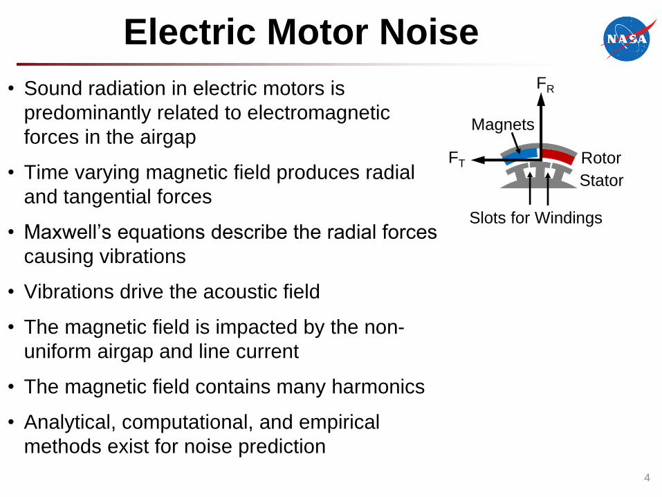
Electric Motor Noise
• Sound radiation in electric motors is
predominantly related to electromagnetic
forces in the airgap
• Time varying magnetic field produces radial
and tangential forces
• Maxwell’s equations describe the radial forces
causing vibrations
• Vibrations drive the acoustic field
• The magnetic field is impacted by the non-
uniform airgap and line current
• The magnetic field contains many harmonics
• Analytical, computational, and empirical
methods exist for noise prediction
Rotor
Stator
Magnets
Slots for Windings
FR
FT
4

SMALL UAS MOTORS
5
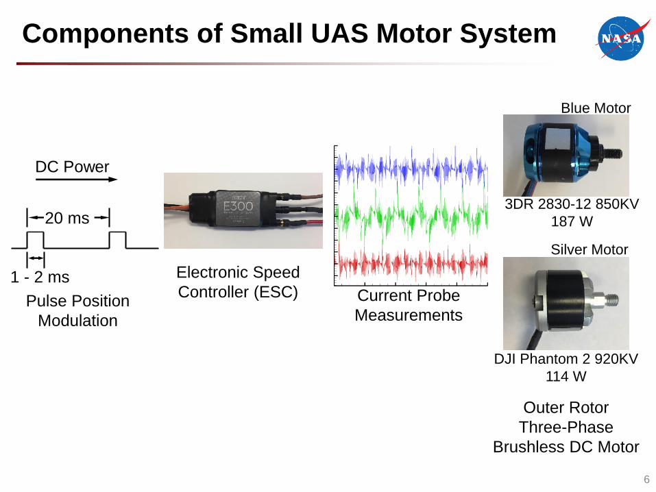
Components of Small UAS Motor System
6
DC Power
20 ms
1 - 2 ms Electronic Speed
Controller (ESC) Current Probe
Measurements
Outer Rotor
Three-Phase
Brushless DC Motor
Pulse Position
Modulation
3DR 2830-12 850KV
187 W
DJI Phantom 2 920KV
114 W
Blue Motor
Silver Motor

Motor Testing in the ATL
7
• Acoustic Test Laboratory (ATL)
– 21 ft x 17 ft x 17 ft anechoic
chamber
– 100 Hz cut-off
• Tests were conducted with a
“tethered” motor mount
• 5 microphones were located on
an 8 in radius arc
• Simultaneous current probes
measurements were made on
the three-phase input to the
motor
• Motor speed measured with
laser tachometerMotor
Microphone
Array
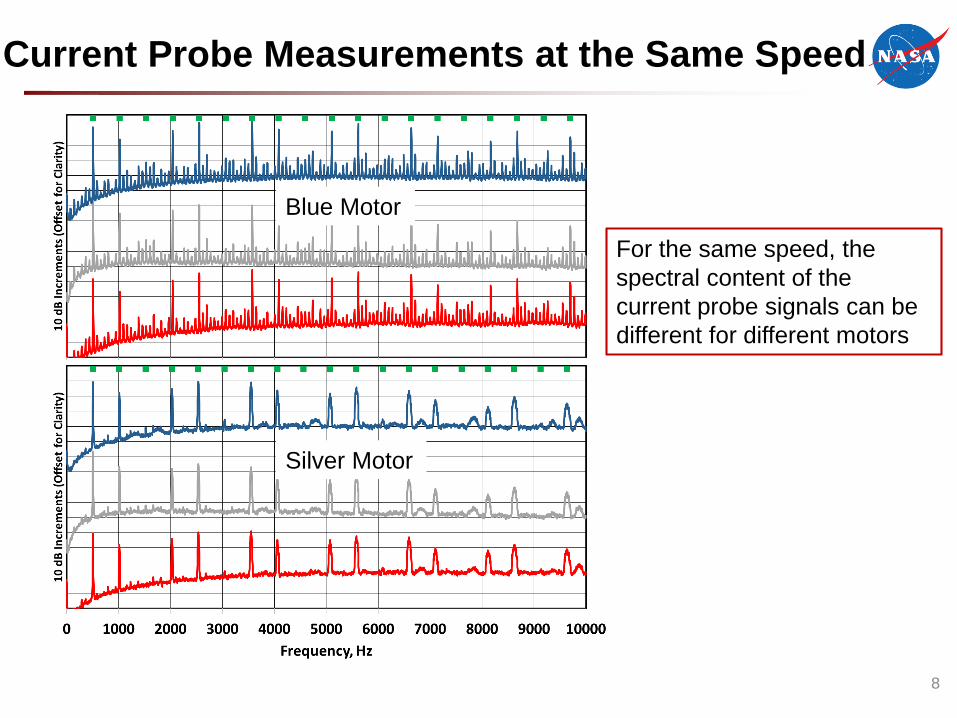
Current Probe Measurements at the Same Speed
8
AOABlue Motor
Silver Motor
For the same speed, the
spectral content of the
current probe signals can be
different for different motors

Current Probe Measurements at Different Speeds
9
4370 RPM
6060 RPM
7340 RPM
For the same motor, the
spectral content of the
current probe signals
depends on the motor speed
Blue Motor

Acoustic Radiation at 4370 RPM
Blue Motor
Silver Motor
Current Probe
Current Probe
Center Microphone
Center Microphone
• Large number of tones in
acoustic spectra
• Amplitudes of acoustic
harmonics can be as large as
the fundamentals
• Number of tones in acoustic
spectra increases with
increasing number of non-
harmonically related current
frequencies
• Peak amplitudes are similar
for two motors and occur at
similar frequencies
10
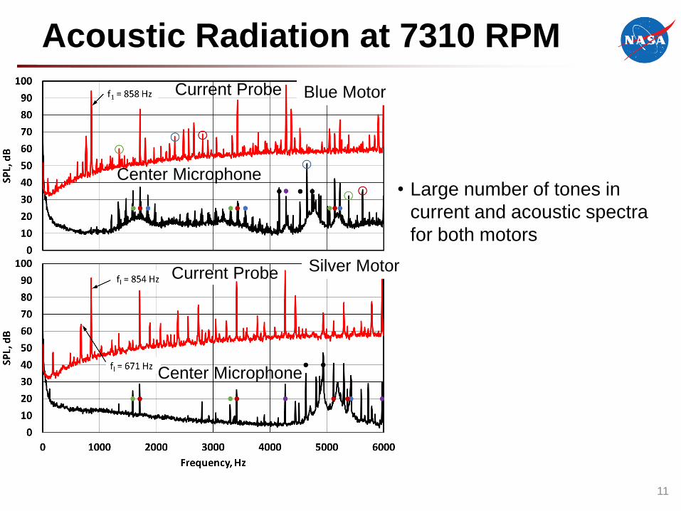
Acoustic Radiation at 7310 RPM
Blue Motor
Silver Motor
Current Probe
Current Probe
Center Microphone
Center Microphone
• Large number of tones in
current and acoustic spectra
for both motors
11
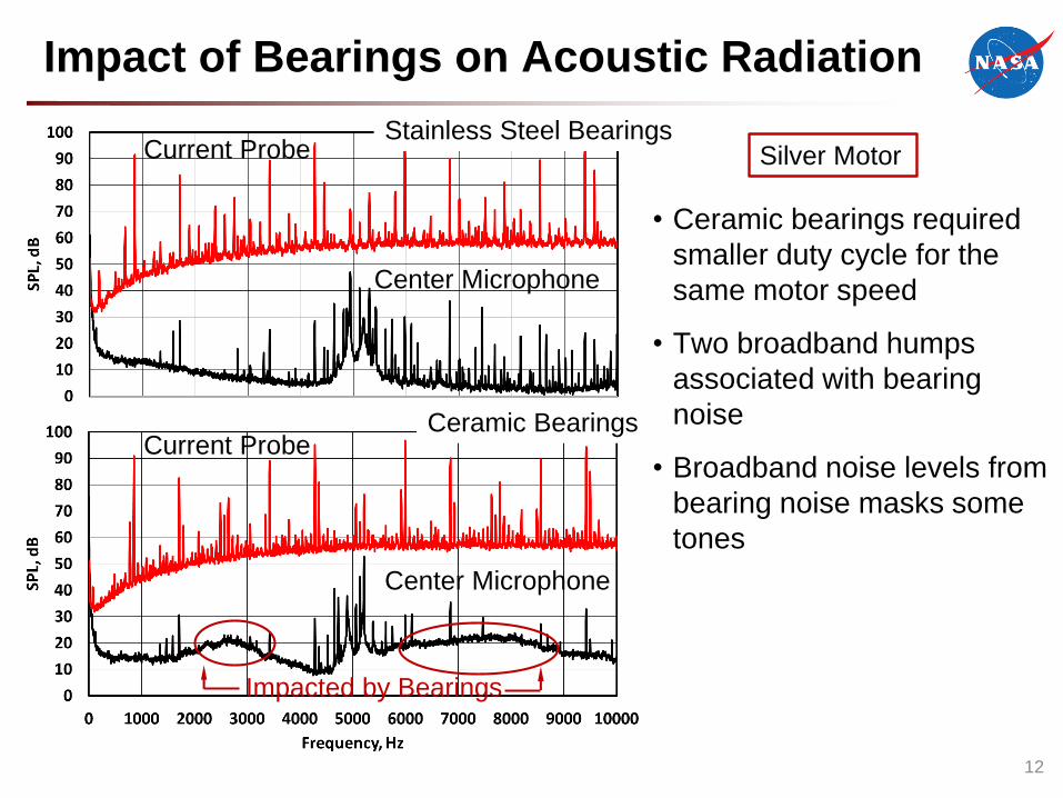
Impact of Bearings on Acoustic Radiation
Current Probe
Current Probe
Center Microphone
Center Microphone
Stainless Steel Bearings
Ceramic Bearings
Impacted by Bearings
• Ceramic bearings required
smaller duty cycle for the
same motor speed
• Two broadband humps
associated with bearing
noise
• Broadband noise levels from
bearing noise masks some
tones
12
Silver Motor

13
Motor Noise Predictions
(Crocker/BBN) (Alger)

OSU MOTOR
14

OSU Setup in Hemi-Anechoic Chamber
15
Thin SideThick SideThick Side Thick Side
Pole 1
Pole 6
RPM
Optical
Sensor• Inductance motor
• No inverter
• Coolant leak limited locations where
acoustic measurements could be
made
Pole 6
Pole 1

Electric Propulsion Concepts
3
Boeing SUGAR-Volt5 – 10 MW
NASA N3-X10 MW +
NASA STARC-ABL~2.6 MW

Current and Acoustic Signatures
Current Probe
Microphone A
fl = 60 Hz
4flZr(1-s)fl/p
Zr(1-s)fl/p + 2fl
Zr = # rotor slots
fl = line frequency
p = # pole pairs
s = slip17

18
Motor Noise Predictions

Conclusions
• For small UAS motors
– Spectral content of current probe signal depends on the motor and motor
speed
– Current probe spectra containing non-harmonic fundamental frequencies
are associated with acoustic spectra containing a significant number of
spectral peaks
– Amplitudes of harmonics in acoustic spectra can be as large as the
fundamentals
• For the larger inductance motor
– The acoustic signals have relatively few spectral peaks (with no inverter)
compared to smaller UAS motors
– The acoustic signal contains spectral peaks associated with the
electromagnetic field and possibly associated with the structure
19

Future Plans
• For small UAS motors
– Repeat measurements for a second electronic speed controller
• Determine if controller data shown here is representative of controllers
used for small UAS motors
• For the larger inductance motor
– Acquire acoustic data for the second generation OSU motor with
inverter
– Investigate different acoustic prediction schemes
• Acquire acoustic data for intermediate size (67 kW) electric
motor (NASA’s X-57 Maxwell Aircraft)
20

BACKUP SLIDE
21
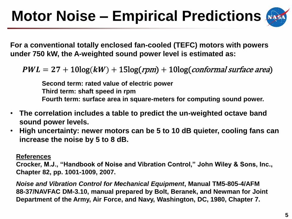
Motor Noise – Empirical Predictions
5
𝑷𝑾𝑳 = 𝟐𝟕 + 10log(𝒌𝑾) + 15log(rpm) + 10log(conformal surface area)
References
Crocker, M.J., “Handbook of Noise and Vibration Control,” John Wiley & Sons, Inc.,
Chapter 82, pp. 1001-1009, 2007.
Noise and Vibration Control for Mechanical Equipment, Manual TM5-805-4/AFM
88-37/NAVFAC DM-3.10, manual prepared by Bolt, Beranek, and Newman for Joint
Department of the Army, Air Force, and Navy, Washington, DC, 1980, Chapter 7.
Second term: rated value of electric power
Third term: shaft speed in rpm
Fourth term: surface area in square-meters for computing sound power.
For a conventional totally enclosed fan-cooled (TEFC) motors with powers
under 750 kW, the A-weighted sound power level is estimated as:
• The correlation includes a table to predict the un-weighted octave band
sound power levels.
• High uncertainty: newer motors can be 5 to 10 dB quieter, cooling fans can
increase the noise by 5 to 8 dB.