electric motor drive for bicycle with...
TRANSCRIPT

ELECTRIC MOTOR DRIVE FOR BICYCLE WITH BATTERY
AN INTERNSHIP REPORT
Submitted by
KIRUBA K (2016105036)
MONICA V (2016105554)
PADMAVATHY S (2016105565)
in fulfillment for the Summer Internship Program
offered by
ELECTRONICS AND COMMUNICATION ENGINEERING
ANNA UNIVERSITY
COLLEGE OF ENGINEERING GUINDY
ANNA UNIVERSITY :: CHENNAI 600 025
MAY - JUNE 2018
COLLEGE OF ENGINEERING GUINDY
ANNA UNIVERSITY :: CHENNAI 600 025
APRIL 2018
INTERNSHIP CERTIFICATE
Certified that this internship report “Electric motor drive for bicycle with
battery” is the work of KIRUBA K (2016105036), MONICA V (2016105554),
PADMAVATHY S (2016105565) who carried out the internship project work
under my supervision from 8th May, 2018 to 7th June, 2018.
DR. S. MUTTANHEAD OF THE DEPARTMENTProfessorECE Department
Anna University, Chennai – 25.
DR. D. SRIDHARANCO-ORDINATORProfessorECE DepartmentCollege of Engineering GuindyAnna University Chennai - 25
DR. J. KAMALASUPERVISORAssistant ProfessorECE DepartmentCollege of Engineering GuindyAnna University Chennai - 25
I. ACKNOWLEDGEMENT
The final outcome of this project required a lot of guidance and assistance from
many people and we are extremely privileged to have got this all along the
completion of this project. All that we have done is only due to such supervision
and assistance and we would not forget to thank them.
We respect and thank our Dean Dr. T.V.Geetha for providing us with this Summer
Internship opportunity as it was a great learning experience for all of us.
We respect and thank the Department of Electronics and Communication
Engineering and Dr.Muttan the HOD, Department of ECE, for providing us the
infrastructure for the completion of our internship project.
We thank Dr.D.Sridharan for allowing us to use the components and facilities of
the Electronics and Communication Department.
We owe our deep gratitude to our project guide and supervisor Dr.J.Kamala, who
took keen interest on our project work and guided us all along, till the completion
of our project work by providing all the necessary information for developing a
good system.
Kiruba K Monica V Padmavathy S

II. ABSTRACT
Electric Bicycles have been gaining attention as an efficient
and clean means of transportation. Our report focuses on the design
and implementation of a hybrid powered electric bicycle employing a
dc-dc power converter. Two DC sources are used: battery and super
capacitor. The super capacitor is connected in parallel to the battery
and a dc-dc converter is designed in closed loop which arbitrates
power between the battery and super capacitor. The purpose of
employing super capacitor is to drive the vehicle during the peak
power required by the load. The main components of the proposed
electric bicycle are: battery, super capacitors, dc-dc converter,
controller and BLDC motor. These components are modeled in
MATLAB. Three topologies of dc-dc converter are investigated for the
electric bicycle and they are compared in terms of ripple at the input
and the output and from the results it is found that the modified
boost converter results in reduced ripple. The lead acid battery and
super capacitor are modeled in SIMULINK to obtain the voltage and
current waveform. A prototype of the proposed dc-dc converter is
built alongwith controller and it is tested.

TABLE OF CONTENTS:
S.No CONTENTS PAGE
I Acknowledgement 03
II Abstract 04
III Introduction 06
IV Proposed topology of power converter for electric bicycle: (A)Boost converter or Step-Up converter (B)Interleaved boost converter (C)Modified boost converter
07
V Simulation of Modified boost converter: (A)Simulink circuit for MBC (B)Output voltage and current waveform (C)Ripple voltage waveform
17
VI Simulation of BLDC drive:
(A)Simulink circuit for BLDC drive (B)Stator Back EMF and Stator Current Waveform(with video embedded) (C)Rotor Speed Waveform (with video embedded) (D)Electromagnetic Torque Waveform (with video
embedded)
20
VII Simulation of electric bicycle with battery: (A)Simulink circuit of electric bicycle with battery (B)Current waveform of battery (C)Voltage waveform of battery (D)SOC characteristics of a battery
24
VIII Hardware implementation 28
IX Estimated cost 32
X Conclusion 33
XI References 34

III.INTRODUCTION
In the present era, there is an increasing demand for
transportation and this has led to the vast development in the area of
electric vehicles. Bicycle is a mode of transportation which is safe and
cheaper and it reduces the air pollution. Therefore, the use of electric
bicycles has increased. Conventionally, dc motors are employed but it
suffers from commutation problem and requires frequent
maintenance. The deployment of Brushless DC motor (BLDC) for e-cycle
overcomes the above problem. The BLDC motor is electrically
commutated by power switches instead of brushes and is highly reliable
since it does not have any brushes to wear out and replace.
The proposed work employs two power sources in parallel
combination which includes the battery and super capacitor. They are
given to the main circuit via a switch and microcontroller decides which
power source has to be utilized over a particular interval of time. The
stator current is measured and when it goes beyond certain load
conditions, super capacitor helps battery by charging it. The fact is that
the super capacitor is used to supply the motor during the peak load
condition where the battery will not be as efficient as possible

From Fig.1, when the motor starts rotating, then the wheel of the cycle
also starts to rotate. Hence the cycle moves forwards with a constant
speed of the motor. The speed can be varied by the use of throttle.
When the rider stops accelerating the throttle, the motor stops and
hence the cycle also stops.
IV.PROPOSED TOPOLOGY OF POWER CONVERTER FOR ELECTRIC
BICYCLE
DC-DC power converters are extensively used in all variety of
applications, including power supplies for computers, industry
equipments, aerospace, telecommunication and motor drives. The
main function of this converter is to obtain a variable dc from a fixed dc

input which can perform buck, boost and buck-boost operation. The
most preferred topology is the boost converter in which the output is
greater than the input voltage. The three different boost topologies
considered in this work are:
Boost Converter
Interleaved Boost Converter
Modified Boost Converter
(A) Boost Converter or Step-Up Converter
A boost converter is a switch mode DC to DC converter in which the
output voltage is greater than the input voltage and the circuit is shown
in Fig.2. It is also called as step up converter. The name step up
converter comes from the fact that analogous to step up transformer
the input voltage is stepped up to a level greater than the input voltage.
By law of conservation of energy the input power has to be equal to
output power (assuming no losses in the circuit).
Input power (Pin) = output power (Pout)
Since Vin < Vout in a boost converter, it follows then that the output
current is less than the input current. Therefore in a boost converter
Vin < Vout and Iin >Iout

Fig.2. Boost converter circuit
The main working principle of boost converter is that the inductor in
the input circuit resists sudden variations in input current. When the
main switch is turned on, the inductor current rises to the maximum
value and energy is stored in the inductor. When the switch is turned
off, the polarity of the emf induced in the inductor reverses as it cannot
the change the direction of current instantaneously and hence the
freewheeling diode is forward biased. As a result, the inductor
discharges and the energy stored in it are transferred to the load and
the inductor current decays. Therefore, the voltage across the load will
be equal to the sum of the supply voltage and voltage across the
inductor. Hence, this converter produces an output greater than the
input voltage, thus performing boosting action. The large time constant
compared to switching period ensures a constant output voltage.

The conversion gain of boost converter is given by
Where Vo is the output voltage, Vin is the input voltage and D is the
duty ratio of boost converter.
The parameters for simulation of boost converter is shown in Table I.
The simulation circuit of boost converter is shown in Fig.3.
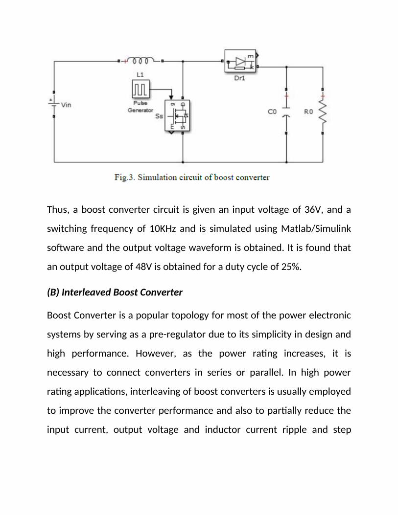
Thus, a boost converter circuit is given an input voltage of 36V, and a
switching frequency of 10KHz and is simulated using Matlab/Simulink
software and the output voltage waveform is obtained. It is found that
an output voltage of 48V is obtained for a duty cycle of 25%.
(B) Interleaved Boost Converter
Boost Converter is a popular topology for most of the power electronic
systems by serving as a pre-regulator due to its simplicity in design and
high performance. However, as the power rating increases, it is
necessary to connect converters in series or parallel. In high power
rating applications, interleaving of boost converters is usually employed
to improve the converter performance and also to partially reduce the
input current, output voltage and inductor current ripple and step

down the converter size effectively. As interleaving doubles the
switching
frequency and effectively reduce the ripple at the input current and
output voltage, the size of energy storage elements also significantly
reduces. Additionally, it improves the transient response and increases
the voltage gain of the converter. The circuit diagram of a two-phase
IBC is shown in Fig.
In general, the frequency and phase shift are same for each
parallel connected unit in the IBC. Operation of two-phase IBC is
explained as follows: when Q1 is turned on the current in the inductor
iL1 increases linearly and at the same time energy is stored in inductor
L1. When Q1 is turned off, diode D1 conducts and the stored energy in

the inductor decreases with a slope of the difference in the input and
output voltage. When the inductor discharges its energy, the transfer
the current to the
load takes place via the diode. Once half switching cycle of Q1 is
completed, Q2 is also turned on and completes same cycle of actions.
The current ripple produced will be very small as there is a cancellation
of ripples due to phase shift of 180˚ in the switching pulses.
The design of magnetic elements in this circuit plays an important role
for storing energy and filtering. The two-phase IBC requires two
identical inductors for achieving balanced current.
The value of the inductor can be calculated as per the following
equation.
Where, M – duty ratio, Vin – Input Voltage, fs-Switching frequency and
Δ𝐼𝐿 – Inductor current ripple.
The value of the capacitor can be calculated by the following equation.

Where, M – duty cycle, fs-Switching frequency, Δ𝑉𝐶 – Change in output
voltage, Io –Output current.
The parameters for simulation of IBC are shown in Table II.
Table II Simulation parameters of IBC
The simulation circuit of two-phase IBC is shown in Fig.

Thus, an interleaved boost converter circuit is given an input voltage of
36V, and a switching frequency of 10KHz and is simulated using
Matlab/Simulink software and the output voltage waveform is
obtained.
It is found that an output voltage of 48V is obtained for a duty cycle of
25%.
(C) Modified Boost Converter
The circuit diagram shown represents the two energy storage systems:
the super capacitor and the battery. According to the load level, the
power semiconductor S1 is on during the time tON. The main challenge
of the work is to use in the same circuit super capacitors and batteries

and to manage the energy in each one, without changing the DC-DC
power converter topology. To get this objective, the circuit was
implemented together with a specific control strategy. The control
strategy should, first of all, control the states of the switches S2 and S3
in order to prolong the autonomy of the electrical vehicle and improve
the efficiency of the circuit. On the other hand, it should avoid
simultaneous operation of the battery and the super capacitors. In this
case, a fast discharge of both energy storage systems would be
observed.
Circuit diagram for modified boost converter
The main blocks of the proposed system are the motor, the DC-DC
converter, the battery, the super capacitors, the controller and the
decision circuit. About the decision circuit, distinct conceptions and
strategies are possible and acceptable. Here, the super capacitors
supply the system when high current peaks are demanded. So, a
current level was defined (Ia-sc) imposing the super capacitors
supplying the system (when: Iload > Ia-SC) or the batteries (when: Iload
< Ia-SC).
V.Simulation of modified boost converter
(A)Simulink circuit for MBC

The parameters for simulation of MBC are shown in Table III
Table III Simulation parameters of MBC
(B)Output voltage and current waveform

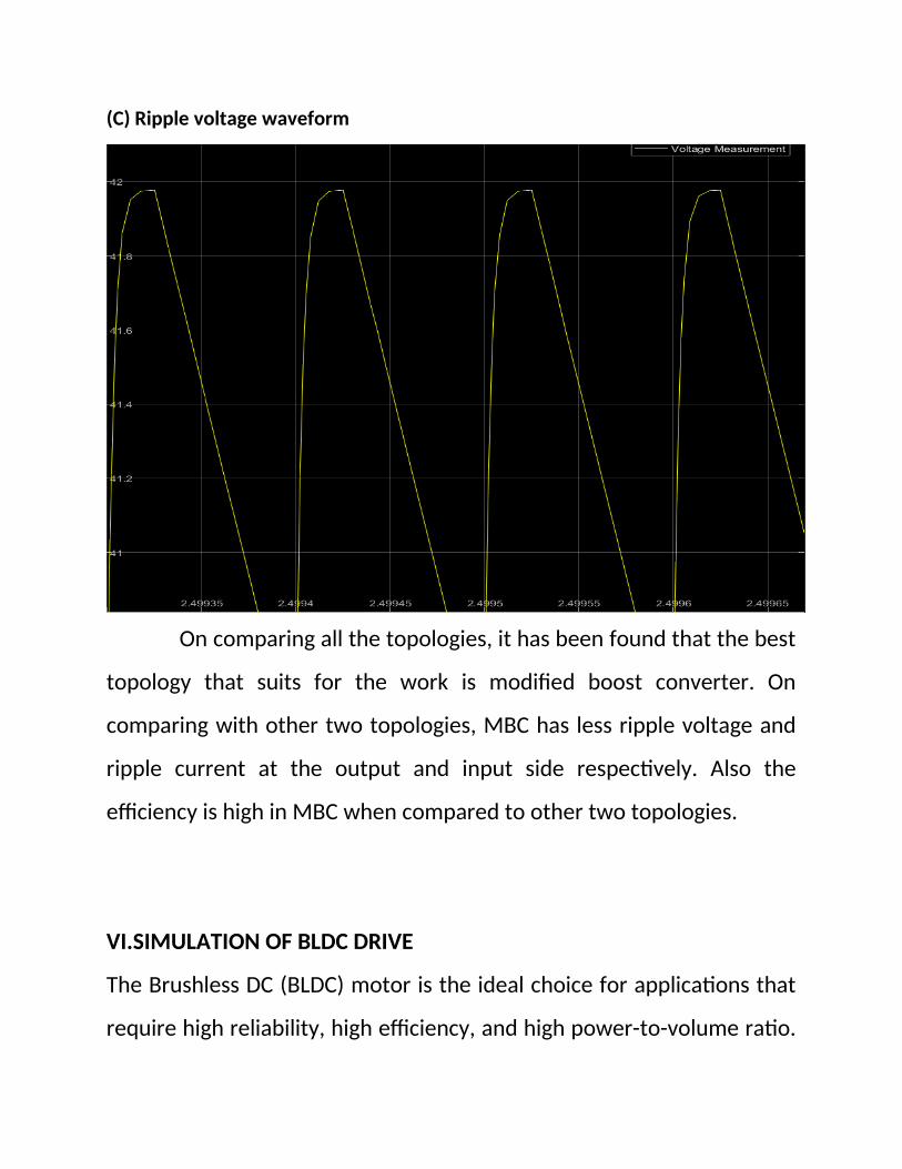
(C) Ripple voltage waveform
On comparing all the topologies, it has been found that the best
topology that suits for the work is modified boost converter. On
comparing with other two topologies, MBC has less ripple voltage and
ripple current at the output and input side respectively. Also the
efficiency is high in MBC when compared to other two topologies.
VI.SIMULATION OF BLDC DRIVE
The Brushless DC (BLDC) motor is the ideal choice for applications that
require high reliability, high efficiency, and high power-to-volume ratio.

Generally speaking, a BLDC motor is considered to be a high
performance motor that is capable of providing large amounts of
torque over a vast speed range. For the proposed electric cycle, BLDC
hub motor is chosen and the simulink model is shown in Fig. below
(A)Simulink circuit for BLDC drive:
(B)Stator Back EMF and Stator Current Waveform (with video embedded)

Stator current and Stator back emf.mp4
(C)Rotor Speed Waveform (with video embedded)

rotor speed.mp4
(D) Electromagnetic Torque Waveform (with video embedded)

Electromagnetic Torque.mp4
VII. Simulation of electric bicycle with battery
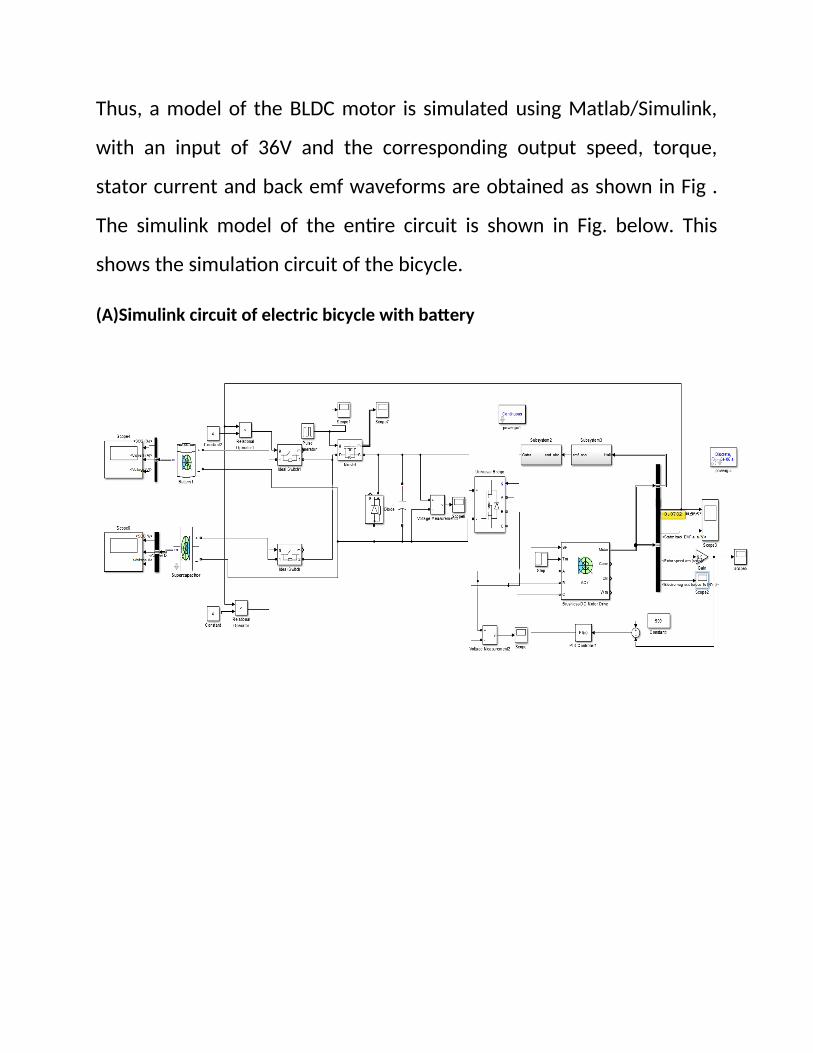
Thus, a model of the BLDC motor is simulated using Matlab/Simulink,
with an input of 36V and the corresponding output speed, torque,
stator current and back emf waveforms are obtained as shown in Fig .
The simulink model of the entire circuit is shown in Fig. below. This
shows the simulation circuit of the bicycle.
(A)Simulink circuit of electric bicycle with battery

(B)Current waveform of battery
(C)Voltage waveform of battery
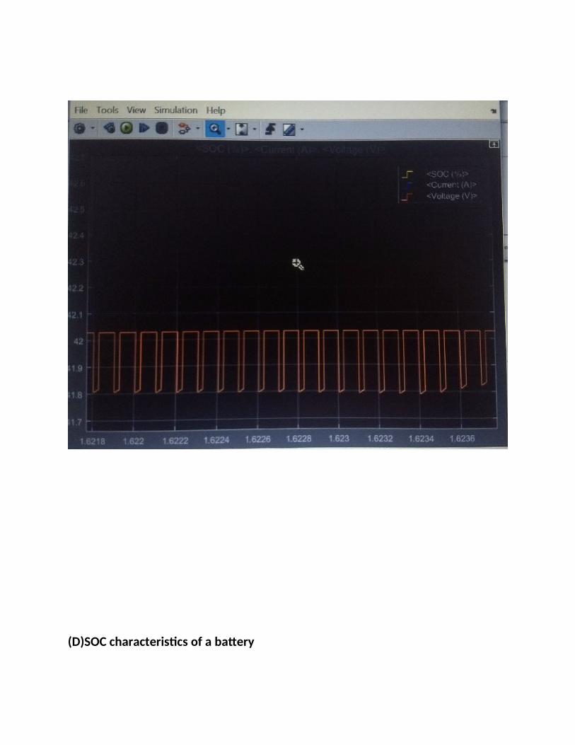
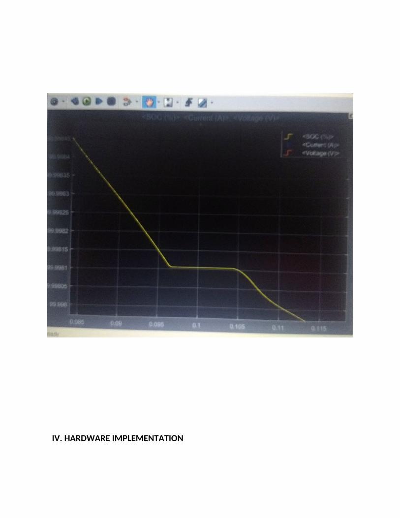
(D)SOC characteristics of a battery
IV. HARDWARE IMPLEMENTATION
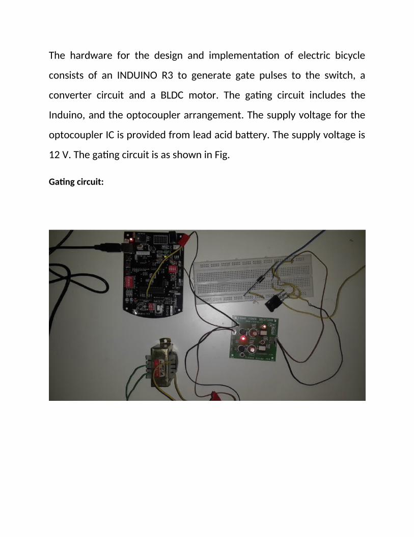
The hardware for the design and implementation of electric bicycle
consists of an INDUINO R3 to generate gate pulses to the switch, a
converter circuit and a BLDC motor. The gating circuit includes the
Induino, and the optocoupler arrangement. The supply voltage for the
optocoupler IC is provided from lead acid battery. The supply voltage is
12 V. The gating circuit is as shown in Fig.
Gating circuit:

When the above circuit is implemented using breadboard and the
output is viewed in a MSO, the following output is obtained.
This is the gate pulse.
The converter circuit consists of power mosfet, fast recovery diode,
output filter capacitor and output load as shown in Fig a. The input to
the converter is given from a series of three batteries. The output of the
converter is given to the BLDC Motor controller. The complete circuit
with is shown in Fig b.

Fig a)
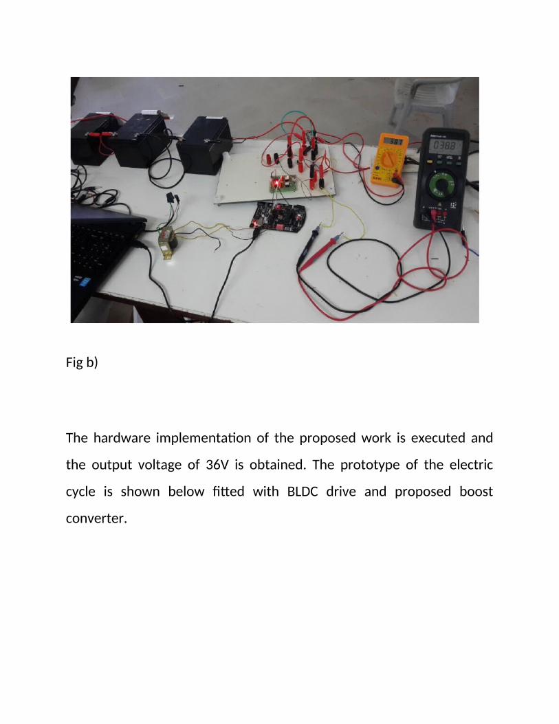
Fig b)
The hardware implementation of the proposed work is executed and
the output voltage of 36V is obtained. The prototype of the electric
cycle is shown below fitted with BLDC drive and proposed boost
converter.

Prototype of electric bicycle
IX.ESTIMATED COST:
Battery -₹1,200
Supercapacitor -₹2,000
Hall effect sensor -₹25
Boost converter -₹289
BLDC motor -₹4,000
PI controller -₹2,750
Total(apprx.) -₹10,264

X.CONCLUSION
The proposed work provides a hybrid storage system which increases
the run time of bicycle, making the system economic and efficient.
Various converter topologies like the interleaved boost converter boost
converter, modified boost converter are analyzed and a comparison of
these topologies is made by calculating the ripple content of the output
voltages .Modified boost converter with its simple circuit, less switching
losses, low ripple content is chosen for the hardware implementation.
For an input voltage of 36V, the bicycle runs at the speed of 25km/hr.
Thus, by using this hybrid powered electric bicycle we can have
pollution less environment.

XI.REFERENCES
1) Burke, A.F. ,‘Batteries and super capacitors for electric, hybrid, and
fuel cell vehicles’, Proc. IEEE, vol. 95, no. 4, pp. 806-820, 2007.
2) Nikhil Hatwar ; Anurag Bisen ; Haren Dodke ; Akshay Junghare and
Milind Khanapurkar, ‘Design Approach for Electric Bikes Using Battery
and Super Capacitor For Performance Improvement’, 16th International
IEEE Annual Conference on Intelligent Transportation Systems , The
Hague, The Netherlands, 2013.
3) Pay, S.; Baghzouz, Y. , ‘Effectiveness of battery-super capacitor
combination in electric vehicles’, Power Tech Conference Proceedings,
IEEE Bologna , vol.3, no., pp. 6 pp. Vol.3, 23-26, 2003.
4) Khaligh, A. and Zhihao, L., ‘Battery, super capacitor, fuel cell, and
hybrid energy storage systems for electric, hybrid electric, fuel cell, and
plug-in hybrid electric vehicles: State-of-the –art’, IEEE Trans. Veh.
Technol, vol. 59, no. 6, pp. 2806-2814, 2010.

5) Solero, L.; Lidozzi, A.; Pomilo, J.A. (2005) ‘Design of multiple-input
power converter for hybrid vehicles’, IEEE Trans. Power Electron., vol.
20, no. 5, pp. 1007–1016, 2005.
THANK YOU