electric heaters and controls for railcar systems
TRANSCRIPT

Electric Heaters and Controls for Railcar Systems
C19-5 425 Hanley Industrial Court
St. Louis, Missouri 63144 ~ USA (314) 644-4300 ~ FAX (314) 644-5332
www.indeeco.com

INTRODUCTION
Founded in 1929 as a family owned and operated business, INDEECO designs and manufactures
commercial and industrial electric heating and control systems. A staff of 250 skilled workers builds state-
of-the-art heaters and complex heating systems. Its 30-plus engineers, technicians, ASME-certified
welders, quality assurance personnel, skilled electronic and electrical assemblers and panelboard
fabricators work together to provide customers with turnkey heating solutions. The creativity and spirit of
discovery that launched INDEECO in an inventor’s basement during the Depression continues today in
four air-conditioned plants totaling more than 190,000 square feet. Since 1968, we have built electric
heating equipment for the Railcar Industry.
CONTENTS
APPLICATIONS FOR RAILCAR HEATERS .......................................................................................... 1 OVERHEAD HVAC HEATERS ........................................................................................................... 2-3 OPEN COIL vs. FINNED TUBULAR DESIGN..................................................................................... 4-6 SIDEWALL/FLOOR HEATERS.............................................................................................................. 7 CAB HEATERS & DEMISTERS............................................................................................................. 8 TUBULAR & FINNED TUBULAR ELEMENT DESIGNS ................................................................... 9-10 TERMINATIONS, MOUNTING HARDWARE & SEALS .................................................................. 11-12 CRANKCASE HEATERS..................................................................................................................... 13

-1-
APPLICATIONS FOR RAILCAR HEATERS Year
Shipped Transit
Authority NominalVoltage Application
1999 ACELA (Amtrak Acela Express) 480 Volts, AC Overhead HVAC Heaters 1995 Amtrak Viewliner 480 Volts, AC Overhead HVAC Heaters 1998 Atlanta Airport People Mover 525 Volts, AC Overhead HVAC Heaters 1996 BART Rehab 1000 Volts, DC Under-Floor HVAC Heaters 2002 Calgary 600 Volts, DC Sidewall (Floor) and Under-Seat Heaters 1995 Caltrans 650 Volts, DC Sidewall (Floor) Heaters 1998 Czech Republic 380 Volts, AC Overhead HVAC Heaters 1994 DART (Dallas) 208 Volts, AC Overhead HVAC Heaters 1997 Hudson-Bergen Line 480 Volts, AC Overhead HVAC Heaters
2001 King County (Seattle) 700 Volts, DC Overhead HVAC Heaters and Cab Heater Element Assemblies
1996 Long Island Railroad 480 Volts, AC Overhead HVAC Heaters & Sidewall (Floor) Heaters
1989 Los Angeles Heavy Rail 750 Volts, DC Overhead HVAC Heaters 1992 MBTA (Boston) 600 Volts, DC Overhead HVAC Heaters
2001 METRA (Chicago) 480 Volts, AC Overhead HVAC Heaters and A/C Compressor Heaters
1992 Metro Link (St. Louis) 700 Volts, DC Overhead HVAC Heaters, Sidewall (Floor) Heaters & Demister Cab Heaters
1996 MTA Marc III (Baltimore) 480 Volts, AC Overhead HVAC Heaters 1996 NJTA, Comet IV 480 Volts, AC Sidewall (Floor) Heaters 1990 New York Transit R-32 & R-32A Cars 600 Volts, DC Overhead HVAC Heaters 1988 New York Transit R-42 & R-68 Cars 600 Volts, DC Overhead HVAC Heaters
2001 NJTA, Comet V 480 Volts, AC Overhead HVAC Heaters and Sidewall (Floor) Heaters
1998 Orlando Airport People Mover 480 Volts, AC Finned Tubular Heaters 1995 Portland TRI-MET 800 Volts, DC Sidewall (Floor) Heaters 2001 Sacramento 120 Volts, AC Cab Heaters and HVAC Heater Elements 2001 Salt Lake City 800 Volts, DC Sidewall (Floor) Heaters 1999 San Francisco Airport People Mover 575 Volts, DC Overhead HVAC Heaters 1999 San Juan, Puerto Rico – Tren Urbano 230 Volts, AC Demister Cab Heaters 1996 SEPTA (Philadelphia) Market Frankfort 600 Volts, DC Overhead HVAC Heaters 1998 Stansted (England) People Mover 525 Volts, AC Overhead HVAC Heaters
1996 Toronto Transit (T1) 600 Volts, DC Overhead HVAC Heaters & Sidewall (Floor) Heaters
1999 Valencia (Venezuela) 700 Volts, DC Demister Cab Heaters 1994 Via Rail (Canada) 480 Volts, AC Overhead HVAC Heaters 1990 Washington Metro (Washington, D.C.) 700 Volts, DC Overhead HVAC Heaters

-2-
OVERHEAD HVAC HEATERS
Figure 1 Open Coil Construction
INDEECO has designed and built both open coil and finned tubular
heaters for a wide variety of space heating applications for more than 40 years. Thirty years ago,
we developed the first open coil heater designed specifically for use in railcar systems. This design differs from open coils for commercial
and industrial applications in the following respects:
High Voltage Terminal Insulatorshave approximately four times the creepage distance between the terminal and ground -- two inches over surface in the railcar design versus 0.5 inches in the commercial HVAC heater design. Moreover, these ceramics are glazed giving a margin of safety at this point of maximum potential difference to ground.
Ribbed Coil Support Insulatorshave approximately six times the creepage distance: the over ceramic surface between the coil and grounded metal is 1.5 inches in the railcar heater design, versus 0.25 inches for commercial HVAC heater designs. See Figure 5, Page 4.
Figure 2
-3-
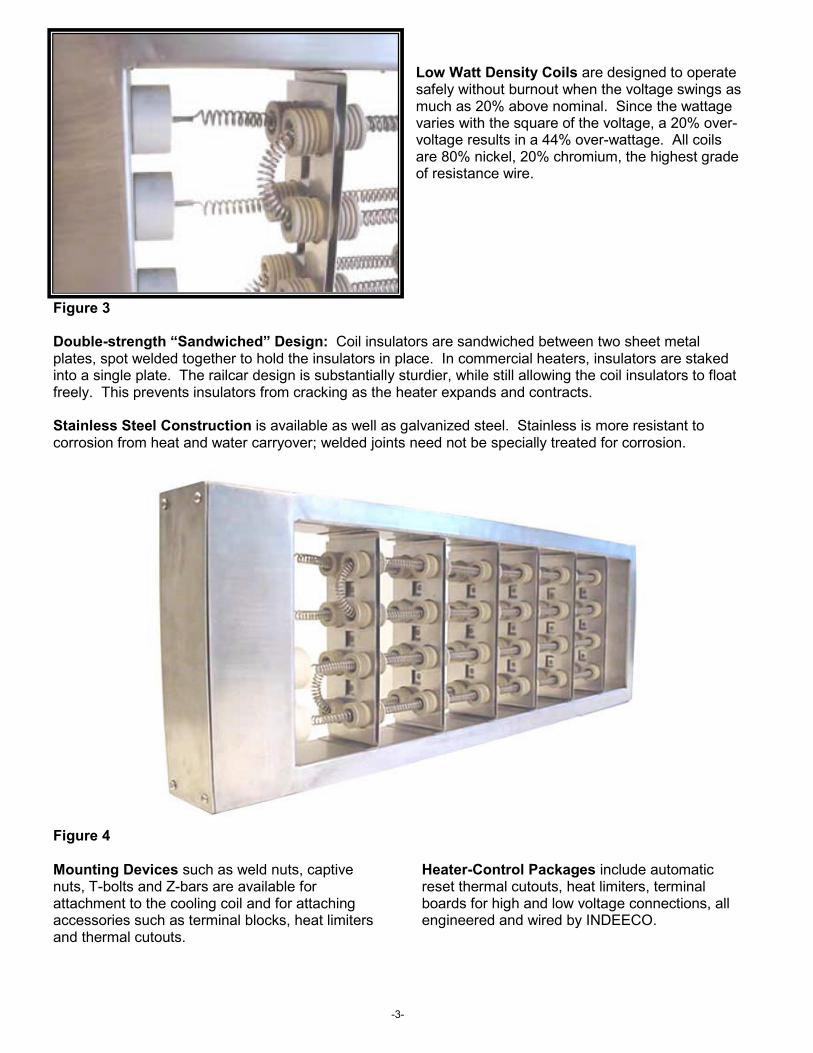
Low Watt Density Coils are designed to operate safely without burnout when the voltage swings as much as 20% above nominal. Since the wattage varies with the square of the voltage, a 20% over-voltage results in a 44% over-wattage. All coils are 80% nickel, 20% chromium, the highest grade of resistance wire.
Figure 3
Double-strength “Sandwiched” Design: Coil insulators are sandwiched between two sheet metal plates, spot welded together to hold the insulators in place. In commercial heaters, insulators are staked into a single plate. The railcar design is substantially sturdier, while still allowing the coil insulators to float freely. This prevents insulators from cracking as the heater expands and contracts.
Stainless Steel Construction is available as well as galvanized steel. Stainless is more resistant to corrosion from heat and water carryover; welded joints need not be specially treated for corrosion.
Figure 4
Mounting Devices such as weld nuts, captive nuts, T-bolts and Z-bars are available for attachment to the cooling coil and for attaching accessories such as terminal blocks, heat limiters and thermal cutouts.
Heater-Control Packages include automatic reset thermal cutouts, heat limiters, terminal boards for high and low voltage connections, all engineered and wired by INDEECO.

-4-
OPEN COIL vs. FINNED TUBULAR DESIGN
ADVANTAGES OF OPEN COIL
No Secondary Insulation: INDEECO’s open coil design eliminates the need for secondary electrical insulation. The coil and terminal insulators provide the necessary electrical creepage for up to 800 volts (Figure 5). Finned tubular elements must be mounted on secondary insulators, as the insulation between coil and sheath is not sufficient to meet this spec.
Creepage & Gap per NFPA Standard 130
2.0
1.5
0.5
Inch
es
0.0 200 400 600 800 1,000
Volts – DC, AC (RMS) Figure 5
Gap: Minimum distance, through air, between metallic parts.
Creepage: Minimum distance between metallic parts along surface of insulating material.
Reduced Weight/Quicker Response: Open coil elements are lightweight in comparison to finned tubular. For railcar heating, a typical open coil element weighs one ounce per foot, allowing it to reach operating temperatures rapidly and cool down quickly when de-energized. The open coil’s response time is substantially less than a finned tubular heater (Figure 6). This results in more accurate temperature control, since the open coil responds more quickly to changes in environmental conditions.
0 1 2 3 4 5
Time in Minutes Figure 6
Withstands High Temperature: Open coil elements can withstand substantially higher temperatures than finned tubular elements. Grade A resistance wire (80% nickel, 20% chromium), which INDEECO uses exclusively, can operate continuously at 2150º F. Although elements in railcar heaters are designed to oper-ate in the black range (approximately 1200º F maximum), this margin of safety means that element burnout is virtually unknown under normal conditions. Furthermore, since the alloy is all nickel and chromium, atmospheric corrosion is eliminated. Even finned tubular elements built entirely from stainless steel will begin to corrode at elevated temperatures.
Withstands Over-Voltage: In railcar applications, the maximum operating voltage is typically 20% higher than the nominal voltage. Since wattage varies as the square of the voltage, these heaters must be designed with a
Creepage
Gap
Open Coil
Finned Tubular
80
70
60
50
40
30
20
10
0
Tem
pera
ture
Ris
e °F

-5-
44% safety factor. Simply by varying the gauge of resistance wire used in an open coil element, the safety factor is achieved. Finned tubular elements, by contrast, do not have this flexibility. To meet a 44% safety factor, 44% more element length must be used. Often space for this additional length is not available due to tight quarters in the overhead compartment.
Low Pressure Drop: Because of the high percentage of open space across the heater, open coils have low pressure drops when compared to finned tubular heaters. Figure 7 shows pressure drops for both constructions and for an open coil with pressure plate attached. (In the railcar application, the cooling coil acts as a pressure plate, so a separate pressure plate is not required.)
VELOCITY OF AIR
(FEET PER MINUTE)
0.010
0.025
0.050
0.100
0.250
0.500
OPEN COIL HEATERWITH PRESSURE PLATE
FINNED TUBULAR HEATERWITHOUT PRESSURE PLATE
OPEN COIL HEATERWITHOUT PRESSURE PLATE
Figure 7
Eliminates Thermal Expansion Problems: As finned tubular elements heat up and cool down, their length increases and decreases. This constant movement can create element wear and distortion, leading to field service problems. Open coil elements, on the other hand, behave quite differently because of their helical shape. As the element heats up, the pitch of the helix decreases slightly (i.e. there is less space between turns) and the coil goes back to its normal shape as it cools down. Open coil elements are designed with at least one wire diameter between turns, substantially more than adequate expansion room.
Withstands Voltage Spikes: Open coil elements are not subject to damage due to high voltage spikes. Finned tubular elements, on the other hand, must be isolated from grounded metal to prevent arcing through the thin layer of magnesium oxide insulation separating the coil from the sheath.
Proven Reliability: Open coil railcar heaters are extremely reliable. They have been in the field for at least 30 years.
ADVANTAGES OF FINNED TUBULAR
Elements Withstand Physical Abuse: Finned tubular elements are more rugged. That is, if the element itself will be subject to physical abuse, finned tubular elements are preferable.
Insulated Coils: If the element is exposed to human contact, open coils should not be used. The reason is obvious: Open coils are electrically live, whereas finned tubular elements have the coil electrically isolated from the exposed sheath.
-6-
ADVANTAGES OF FINNED TUBULAR (continued)
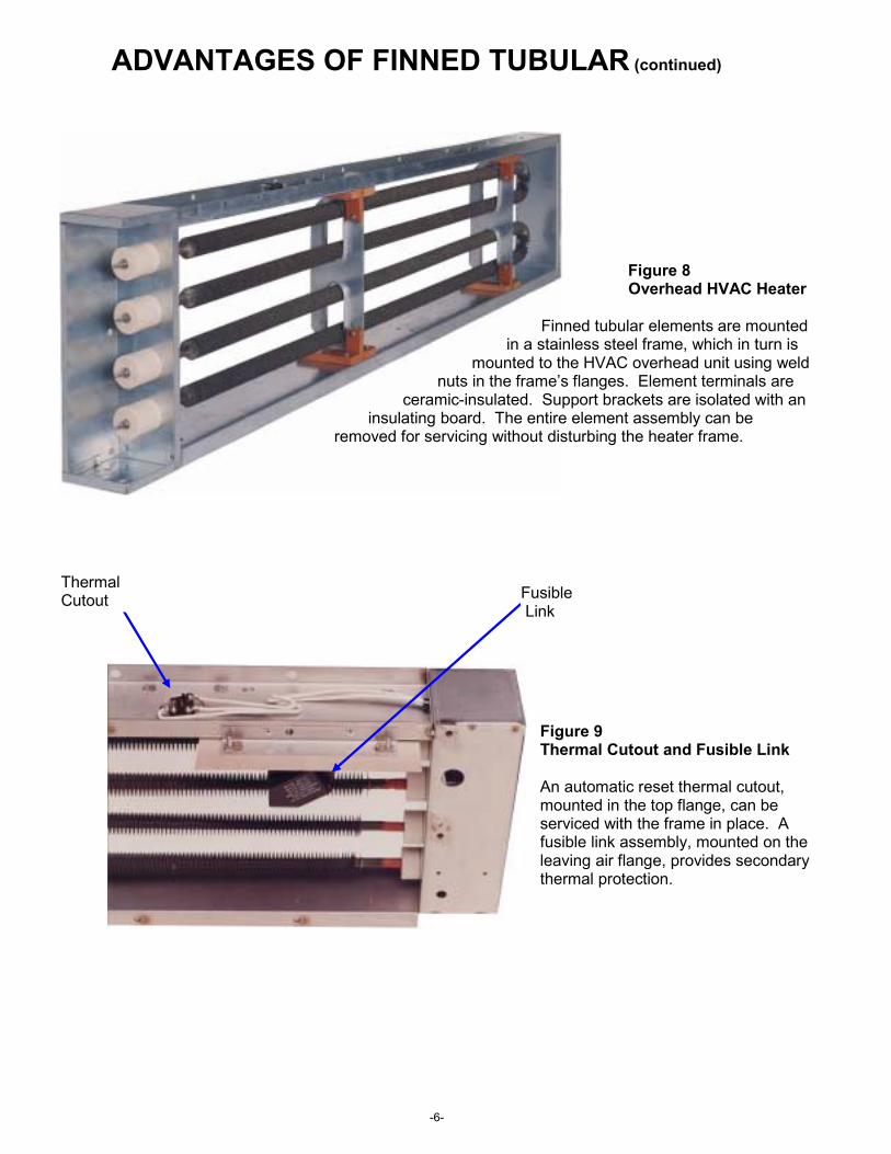
Figure 8 Overhead HVAC Heater
Finned tubular elements are mounted in a stainless steel frame, which in turn is
mounted to the HVAC overhead unit using weld nuts in the frame’s flanges. Element terminals are
ceramic-insulated. Support brackets are isolated with an insulating board. The entire element assembly can be
removed for servicing without disturbing the heater frame.
Figure 9 Thermal Cutout and Fusible Link
An automatic reset thermal cutout, mounted in the top flange, can be serviced with the frame in place. A fusible link assembly, mounted on the leaving air flange, provides secondary thermal protection.
Fusible Link
Thermal Cutout
-7-
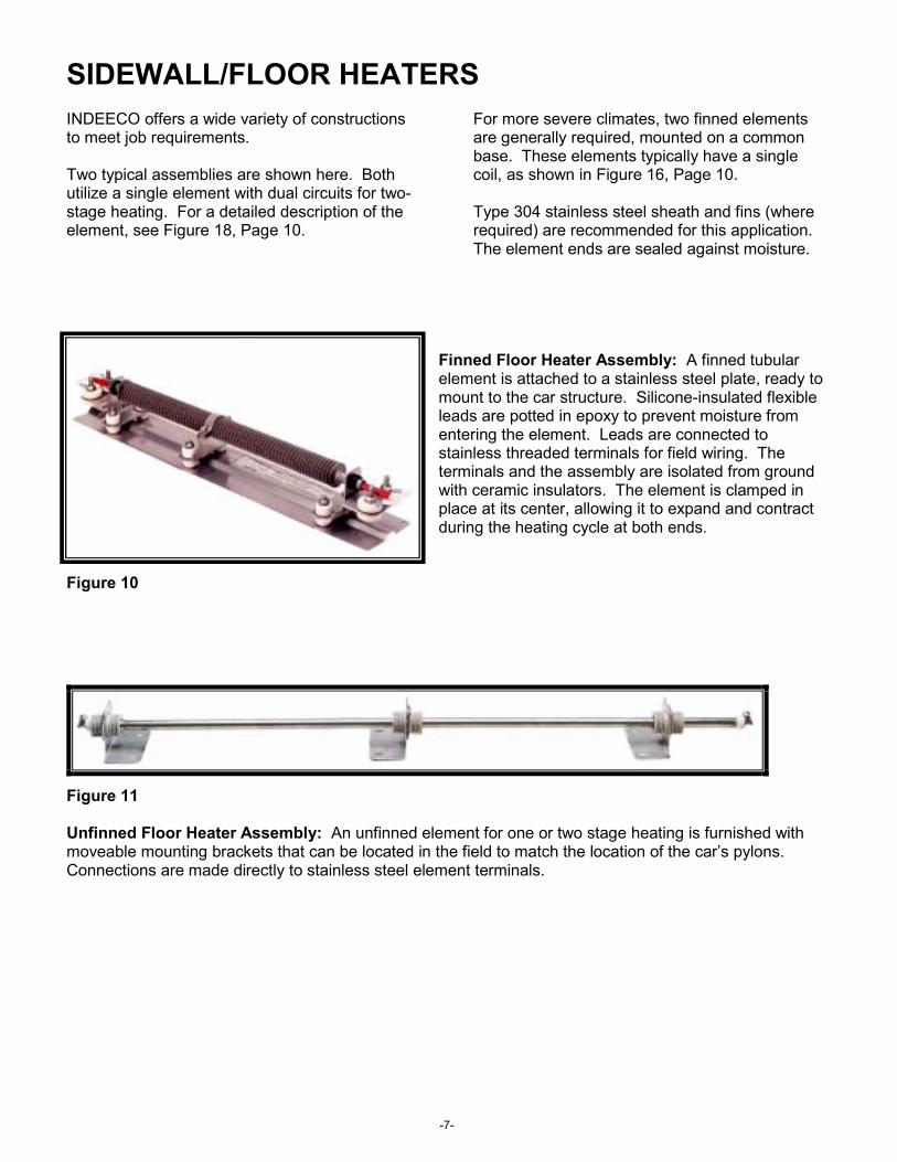
SIDEWALL/FLOOR HEATERS INDEECO offers a wide variety of constructions to meet job requirements.
Two typical assemblies are shown here. Both utilize a single element with dual circuits for two-stage heating. For a detailed description of the element, see Figure 18, Page 10.
For more severe climates, two finned elements are generally required, mounted on a common base. These elements typically have a single coil, as shown in Figure 16, Page 10.
Type 304 stainless steel sheath and fins (where required) are recommended for this application. The element ends are sealed against moisture.
Finned Floor Heater Assembly: A finned tubular element is attached to a stainless steel plate, ready to mount to the car structure. Silicone-insulated flexible leads are potted in epoxy to prevent moisture from entering the element. Leads are connected to stainless threaded terminals for field wiring. The terminals and the assembly are isolated from ground with ceramic insulators. The element is clamped in place at its center, allowing it to expand and contract during the heating cycle at both ends.
Figure 10
Figure 11
Unfinned Floor Heater Assembly: An unfinned element for one or two stage heating is furnished with moveable mounting brackets that can be located in the field to match the location of the car’s pylons. Connections are made directly to stainless steel element terminals.

-8-
CAB HEATERS & DEMISTERS Three typical cab heater designs are shown below, all with covers removed for clarity.
INDEECO designs and fabricates the heating elements, sheet metal enclosures and internal wiring. These in-house capabilities are unique in the cab heater field. All units are tested after assembly under full power.
Cab Heater/Demister: A dual inlet centrifugal blower forces air over two tubular elements for two stage heating. An automatic reset thermal cutout mounted in the top left portion of the enclosure provides over-temperature protection. The heater element can be designed for full line voltage or low voltage operation. The fan operates at 24 volts. Terminal blocks are furnished for both power and low voltage control. Built-in relays are available, but in Figure 12 they were remotely mounted. Two of the four outlets are connected to hoses for demisting thewindshield. The other two warm the cab.
Figure 12
Under-Seat Cab Heater: A single inlet centrifugal blower forces air over the tubular elements. Two levels of thermal protection are provided: An automatic reset thermal cutout acts as the primary protector. A manual reset thermal cutout furnishes backup protection. In this design, both fan and heaters operate at 230 volts AC. A starter capacitor is mounted on the left side of the blower motor. Solid state relays behind the motor are provided for heater operation. Power and control connections are made through the two bushings in the top of the cabinet. Multi-pin connectors are also available.
Multi-Stage Cab Heater: Built to operate from a 230 volt, 3 phase power source, this heater features a five-position selector switch for three heating stages, a fan only setting and “power-off.” A three-speed fan, keyed to the heating stages, keeps the outlet air temperature relatively constant. Two levels of thermal protection are provided: An automatic reset thermal cutout acts as the primary protector. A manual reset thermal cutout provides backup protection. A single multi-pin connector for power and control wiring was provided, along with two nozzles to demist the windshield and a third (not shown) to warm the cab area.
Figure 14
Figure 13
-9-
TUBULAR & FINNED TUBULAR ELEMENT DESIGNS
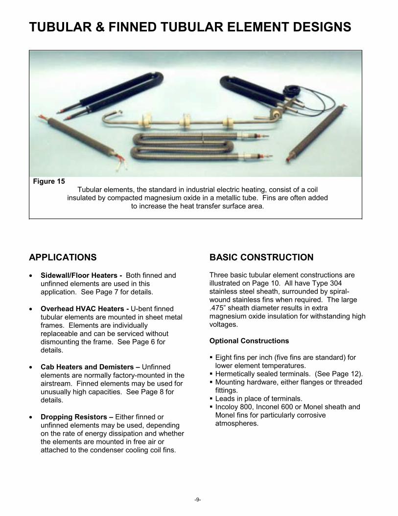
Figure 15 Tubular elements, the standard in industrial electric heating, consist of a coil
insulated by compacted magnesium oxide in a metallic tube. Fins are often added to increase the heat transfer surface area.
APPLICATIONS
• Sidewall/Floor Heaters - Both finned and unfinned elements are used in this application. See Page 7 for details.
• Overhead HVAC Heaters - U-bent finned tubular elements are mounted in sheet metal frames. Elements are individually replaceable and can be serviced without dismounting the frame. See Page 6 for details.
• Cab Heaters and Demisters – Unfinned elements are normally factory-mounted in the airstream. Finned elements may be used for unusually high capacities. See Page 8 for details.
• Dropping Resistors – Either finned or unfinned elements may be used, depending on the rate of energy dissipation and whether the elements are mounted in free air or attached to the condenser cooling coil fins.
BASIC CONSTRUCTION
Three basic tubular element constructions are illustrated on Page 10. All have Type 304 stainless steel sheath, surrounded by spiral-wound stainless fins when required. The large .475” sheath diameter results in extra magnesium oxide insulation for withstanding high voltages.
Optional Constructions
Eight fins per inch (five fins are standard) for lower element temperatures. Hermetically sealed terminals. (See Page 12). Mounting hardware, either flanges or threaded
fittings. Leads in place of terminals. Incoloy 800, Inconel 600 or Monel sheath and
Monel fins for particularly corrosive atmospheres.

-10-
SINGLE-PASS ELEMENT
A single coil is precisely centered in the sheath, maximizing the amount of compacted magnesium oxide insulation between coil and sheath. Terminals are welded to the coil at each end. Elements can be U-bent to place terminals side-by-side. Electrical isolation from ground is recommended if the line voltage exceeds 480V.
Figure 16
TWO-PASS ELEMENT
A single coil makes two passes through the sheath, placing both terminals or leads at the same end. Electrical isolation from ground is recommended if the line voltage exceeds 240V.
Figure 17
TWO-PASS, DUAL CIRCUIT ELEMENT
Two independent coils, each with terminals at opposite ends, make this element suitable for two stage heating. This design is especially useful for floor/perimeter heating, where two stages are typically required. Instead of using two elements, both stages are incorporated into a single element, saving installation time and significantly reducing weight. Electrical isolation from ground is recommended if the line voltage exceeds 240V.
Figure 18
Fins If Required
Heating Coil Spot Weld
SheathSilicone RubberInsulator
Spot Weld
10-32 Stainless Steel Terminal
Compacted Magnesium Oxide Cold Pin
Fins If Required Heating
Coil Sheath Silicone Insulation
Leadwire or Terminals
ColdPin
Compacted Magnesium Oxide
Fins If Required Heating
Coil
Ceramic Bushing
Compacted Magnesium Oxide ColdPin Spot Weld
10-32 Stainless Steel Terminal Both Ends
Sheath
Silicone Insulation

-11-
TERMINATIONS, MOUNTING HARDWARE & SEALS The following drawings illustrate some of the more popular options available. If your application requires a construction not shown, consult INDEECO for custom options.
Standard element with threaded fitting for mounting. Standard terminals, terminal insulators and epoxy moisture barriers are shown. Hardware (not shown) is furnished for fitting and terminals.
Figure 19
Standard element with threaded fitting for mounting and epoxy- sealed leads. Hardware (not shown) is furnished for fitting.
Figure 20
Two-pass or dual circuit element with parallel terminals.
Fins If Required
¾” – 16 UNF-2A Stainless Steel
Threaded Fitting
10-32 Stainless Steel Terminal
Silicone RubberInsulator
Epoxy Barrier – Each End
¾”-16 UNF-2AStainless Steel
Threaded Fitting
Stainless Steel Over Epoxy Seal
FinsIf Required
Stripped End
Lead Wire
Figure 21
Fins If Required
10-32 Stainless Steel Terminal
Ceramic Cap
ElementSheath 1”
2”

-12-
Two-pass or dual circuit element with threaded fitting for mounting and epoxy-sealed leads. Hardware (not shown) is furnished for fitting.
Figure 22
Standard element with ceramic-to- metal hermetic seal.
Figure 23
Dual-circuit element with right-angle terminals and mounting brackets electrically isolated from the element sheath.
Figure 24
Mounting bracket for standard U-bent element.
Figure 25
Strip Leads
Epoxy Seal ¾”-16 Stainless Steel Fitting
Fins If Required
Metal Sleeve
ThreadedTerminal
Element Ceramic
Metal Cap
Cold Pin
10-32 Stainless Steel Terminal
Stainless Steel Fixed Bracket
FieldMounting
Hole
Stainless Steel Tube Crimped To Lock BracketIn Place
Stainless Steel Floating Bracket
11/16” 11/16”
1 5/8”
CeramicBushing
Ceramic Bushing
1 5/8” 1 3/8”
4 1/2”
4 1/4”
2 1/2”

-13-
CRANKCASE HEATERS INDEECO designed and built the first compressor crankcase heaters on the market in 1958. Since then we have developed designs for a wide variety of semi-hermetic compressors as shown in Catalog C66.
Special constructions, such as the one illustrated below, include lead insulation and flexible liquid-tight conduit often required for undercar installation.
Figure 26 Crankcase Heater 75 Watts at 38 VDC
Hypalon or ExaneInsulated (3.64”) Leads
LeadStripped
Nut
½” InsulatedStraight Connector
Liquid-Tight FlexibleConduit Type EF
½” InsulatedStraight Connector
Threaded Female Fitting
Silver Solder
LeadLength
Conduit Length
4.000”
2.750”
2.250”
.494”
.500”

INDUSTRIAL ENGINEERING & EQUIPMENT CO. 425 HANLEY INDUSTRIAL COURT
ST. LOUIS, MO 63144 314-644-4300
Fax: 314-644-5332 www.indeeco.com
MKL - 3494 - 00