electric drives with wide bandgap devices for two-phase
TRANSCRIPT

Electric Drives with Wide Bandgap Devices forTwo-Phase Very Low Inductance Machines
Yibin Zhang, Student Member, IEEE, Damien Lawhorn, Student Member, IEEE, Peng Han, Member, IEEE,Aaron M. Cramer, Senior Member, IEEE, and Dan M. Ionel, Fellow, IEEE
SPARK and SCOPE Labs, ECE Dept., University of Kentucky, Lexington, KY, [email protected], [email protected], [email protected], [email protected], [email protected]
Abstract—Slotless and coreless machines with low inductanceand low core losses are attractive for high speed and high powerdensity applications. With the increase in fundamental frequency,typical drive implementations using conventional silicon-baseddevices are performance limited and also produce large currentand torque ripples. This paper presents a systematic study ofproposed drive configurations implemented with wide bandgap(WBG) devices in order to mitigate such issues for 2-phase verylow inductance machines. Two inverter topologies, i.e., a dualH-bridge inverter with maximum redundancy and survivabilityand a 3-leg inverter for reduced cost, are considered. Feasiblemodulation schemes are derived based on theoretical analysisand the associated maximum output voltages are identified.Simulation and experimental results are provided to validate thefeasibility of drive systems and the effectiveness of analysis.
Index Terms—Axial flux permanent magnet machines, corelessmachines, electric drives, operating range, two-phase, very lowinductance machines, wide bandgap.
I. INTRODUCTION
Low inductance machines have shown attractiveness forvarious applications, especially where high speed operationis required [1], [2]. However, with pulse width modulation(PWM) inverters, low inductance machines typically show vis-ible switching reflected current harmonics. Though the dc busutilization is improved at high speed, PWM voltage producesconsiderable harmonics in machine currents, degrading theefficiency and reliability of drive systems [3].
In conventional drive systems for low inductance machines,filters, such as LC and LCL filters have to be implementedto reduce PWM reflected current harmonics [4]. LC filters donot contain any resistive components, so the voltage/currentwaveform distortion appears especially in LC resonant area,and leads to circulating currents between the inverter and thefilter [5]. Active damping compensation and LCL filters havebeen proposed to address the aforementioned issues. However,the cost, weight, and volume added by the filters still need tobe reduced.
Wide band-gap (WBG) semiconductor devices, such as SiCMOSFETs, enable the PWM frequency capability of 50 to100 kHz or even higher, which keeps the current ripple withinacceptable limits for low inductance machine drives [6]. WBGsemiconductors outperform silicon counterparts in terms of on-resistance. Employing one H-bridge for each phase is the mostcommon drive topology which offers the highest per-phase dcbus utilization but at the same time the highest number ofdevices and cost [7]. Additionally, the increase of the switching
speed in power devices increases the power density of powerelectronic converters as it reduces the weight and volume ofpassive components [8].
To further improve the compactness, reduce low cost, andenhance the robustness, single-phase and two-phase machineshave been increasingly drawing attention [9]. Single-phase andtwo-phase motors work well in constant-speed applications butshow difficulties when variable-speed performance is needed[10]. To improve the variable-speed capability of 2-phasemachines, it becomes necessary to explore alternative invertertopologies and associated modulation schemes and the optimaluse of WBG devices in 2-phase machine drives [11], [12].
In this paper, two drive configurations (in Fig. 1) for two-phase low inductance machines are studied in terms of theoperating capability, survivability, and cost. For the proposeddual H-bridge drive topology, each phase is electrically iso-lated and driven by one H-bridge and a separate dc supply.In the case of failure in one phase, the other phase is stillcapable of supplying the motor. However, the dual-topologyconsists of a large number of switching devices, two capacitorswith high capacitances, and multiple supplies, which mayincrease the system cost. A 3-leg topology as a cost-effectivesolution is proposed and studied. A noticeable limitation of 3-leg inverters in driving two-phase motors is that the root meansquare (RMS) value of the common leg current is higher thanthose of the other two legs that necessitates the utilization ofswitches with higher current ratings at least in one leg. Thelow inductance machines under study are coreless axial-fluxpermanent-magnet (AFPM) machines comprised of multiplerotors and stators with Litz wire or printed circuit boardwindings. And the two phases of the coreless AFPM machineare electrically and magnetically isolated.
II. MODULATION FOR DUAL H-BRIDGE INVERTER
The first topology, referred to as the dual H-bridge inverter,consists of two independent H-bridges and two separate dcsources, as illustrated in Fig. 1a. Each phase winding of thetwo-phase machine is supplied by a single H-bridge, whichprovides full electrical isolation between two phases. The twophase windings are also magnetically isolated since they aredesigned to have a displacement of 90 electrical degrees.This drive configuration is expected to have the maximumreliability considering the inherent electrical and magneticisolation between two phases.
Authors’ manuscript version accepted for publication. The final published version is copyrighted by IEEE and available as: Y. Zhang, D. Lawhorn, P. Han, A. M. Cramer and D.M. Ionel, “Electric Drives with Wide Bandgap Devices for Two-Phase Very Low Inductance Machines,” 2020 IEEE Energy Conversion Congress and Exposition (ECCE), Detroit,MI, USA, 2020, pp. 6125-6129, doi: 10.1109/ECCE44975.2020.9235388. ©2020 IEEE Copyright Notice. “Personal use of this material is permitted. Permission from IEEE mustbe obtained for all other uses, in any current or future media, including reprinting/republishing this material for advertising or promotional purposes, creating new collective works,for resale or redistribution to servers or lists, or reuse of any copyrighted component of this work in other works.”

(a) (b)
Fig. 1. Proposed inverter topologies for two-phase very low inductance machines considered in the study: (a) two H-bridges supplied by two separate dcsources, (b) a three-leg inverter with one leg shared by two phases, which has a cost advantage of 1/4 fewer switches and one dc supply.
To drive the two-phase machine with the dual H-bridgeinverter topology, suitable modulation schemes have to bederived. To produce the rotating magnetic field required fortorque production, the fundamental components of the inverteroutput voltages are required to have the same amplitude and aphase shift of 90 electrical degrees. Assuming the amplitude ofthe inverter output voltage is V , the fundamental componentsof the two phase voltages for the dual H-bridge inverter are:
¢¨¨¦¨¨¤
VPhA VAO VAO
m Vdc
2 cosωt ϕ,
VPhB VBO VBO
m Vdc
2 cosωt ϕ π~2,
(1)
where VPhA and VPhB are the terminal voltages of Phase Aand Phase B windings, respectively. O is the middle point ofthe dc bus. VAO and VBO represent the voltage of A andB to O, respectively. m and Vdc are the modulation index anddc voltage amplitude, respectively. The angular frequency ofthe two-phase machine ω is obtained from ω 2πf , and ϕ isthe initial phase of the reference wave. Equation (1) indicatesthe carrier-based sinusoidal PWM (SPWM) scheme can beused for the dual H-bridge inverter.
III. MODULATION FOR DUAL 3-LEG INVERTER
The second topology is a 3-leg inverter (Fig. 1b). Each phasewinding of the machine is supplied by one H-bridge but oneleg is shared by two phases. This change reduces the numberof required WBG devices by 1/4 and is more attractive interms of the system cost. Compared with the dual H-bridge,the 3-leg topology is more susceptible to failures of powersupply, in which case both phase windings are out of powerand fault-tolerant operation becomes impossible.
The fundamental components of the two phase voltages forthe 3-leg inverter are similar to those expressed by equation(1) except that “A” and “B” are replaced by N :
¢¨¨¦¨¨¤
VPhA VAO VNO
m Vdc
2 cosωt ϕ,
VPhB VBO VNO
m Vdc
2 cosωt ϕ π~2.
(2)
Fig. 2. Reference signals of the two inverter topologies with variousmodulation schemes (full modulation).
The solution that can achieve the maximum reference am-plitude is:
¢¨¦¨¤
VAO m Vdc
2 2
3cosωt 1
3sinωt ,
VNO m Vdc
2 1
3cosωt 1
3sinωt ,
VBO m Vdc
2 1
3cosωt 2
3sinωt .
(3)
Equation (3) indicates both the carrier-based SPWM andspace vector PWM (SVPWM) can be used for the 3-leginverter. In the case of SVPWM, the phase voltage is notsymmetrical due to the unbalance in VAO, VN and VBO,as shown in Fig. 2.
IV. THE OPERATING RANGE ANALYSIS AND SIMULATION
A physical phase variable model of the two-phase core-less AFPM machine is developed, whose PM flux linkageand phase inductance are extracted from 3-dimensional finiteelement analysis (FEA). It has been shown that corelessdesigns usually have very low inductance and the selectionof switching frequency plays an important role in improvingthe system performance [13].
The operating range is first analyzed for the two proposedconfigurations (shown in Fig. 3). The simulation results for thetwo inverters with various modulation schemes are presentedin Fig. 4. And the simulation results of phase currents areshown in Fig. 5.
The two-phase motor is operated at 266.67Hz fundamentalfrequency with full load. The phase currents Ia and Ib for the
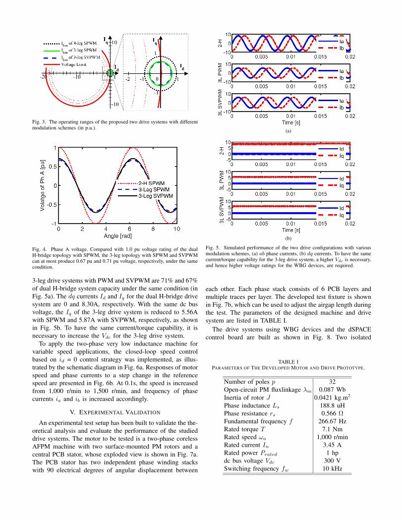
Fig. 3. The operating ranges of the proposed two drive systems with differentmodulation schemes (in p.u.).
Fig. 4. Phase A voltage. Compared with 1.0 pu voltage rating of the dualH-bridge topology with SPWM, the 3-leg topology with SPWM and SVPWMcan at most produce 0.67 pu and 0.71 pu voltage, respectively, under the samecondition.
3-leg drive systems with PWM and SVPWM are 71% and 67%of dual H-bridge system capacity under the same condition (inFig. 5a). The dq currents Id and Iq for the dual H-bridge drivesystem are 0 and 8.30A, respectively. With the same dc busvoltage, the Iq of the 3-leg drive system is reduced to 5.56Awith SPWM and 5.87A with SVPWM, respectively, as shownin Fig. 5b. To have the same current/torque capability, it isnecessary to increase the Vdc for the 3-leg drive system.
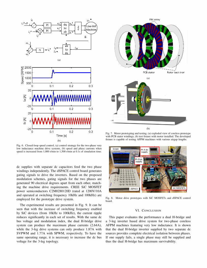
To apply the two-phase very low inductance machine forvariable speed applications, the closed-loop speed controlbased on id = 0 control strategy was implemented, as illus-trated by the schematic diagram in Fig. 6a. Responses of motorspeed and phase currents to a step change in the referencespeed are presented in Fig. 6b. At 0.1s, the speed is increasedfrom 1,000 r/min to 1,500 r/min, and frequency of phasecurrents ia and ib is increased accordingly.
V. EXPERIMENTAL VALIDATION
An experimental test setup has been built to validate the the-oretical analysis and evaluate the performance of the studieddrive systems. The motor to be tested is a two-phase corelessAFPM machine with two surface-mounted PM rotors and acentral PCB stator, whose exploded view is shown in Fig. 7a.The PCB stator has two independent phase winding stackswith 90 electrical degrees of angular displacement between
(a)
(b)
Fig. 5. Simulated performance of the two drive configurations with variousmodulation schemes, (a) ab phase currents, (b) dq currents. To have the samecurrent/torque capability for the 3-leg drive system, a higher Vdc is necessary,and hence higher voltage ratings for the WBG devices, are required.
each other. Each phase stack consists of 6 PCB layers andmultiple traces per layer. The developed test fixture is shownin Fig. 7b, which can be used to adjust the airgap length duringthe test. The parameters of the designed machine and drivesystem are listed in TABLE I.
The drive systems using WBG devices and the dSPACEcontrol board are built as shown in Fig. 8. Two isolated
TABLE IPARAMETERS OF THE DEVELOPED MOTOR AND DRIVE PROTOTYPE.
Number of poles p 32Open-circuit PM fluxlinkage λm 0.087 WbInertia of rotor J 0.0421 kg.m2
Phase inductance Ls 188.8 uHPhase resistance rs 0.566 ΩFundamental frequency f 266.67 HzRated torque T 7.1 NmRated speed ωn 1,000 r/minRated current In 3.45 ARated power Prated 1 hpdc bus voltage Vdc 300 VSwitching frequency fw 10 kHz
(a)
(b)
Fig. 6. Closed-loop speed control, (a) control strategy for the two-phase verylow inductance machine drive systems, (b) speed and phase currents whenspeed is increased from 1,000 r/min to 1,500 r/min at 0.1s of simulation time.
dc supplies with separate dc capacitors feed the two phasewindings independently. The dSPACE control board generatesgating signals to drive the inverters. Based on the proposedmodulation schemes, gating signals for the two phases aregenerated 90 electrical degrees apart from each other, match-ing the machine drive requirements. CREE SiC MOSFETpower semiconductors C2M0280120D (rated at 1200V/10Aand operated at switching frequency 10kHz and 100kHz) areemployed for the prototype drive system.
The experimental results are presented in Fig. 9. It can beseen that with the increase of switching frequency enabledby SiC devices (from 10kHz to 100kHz), the current ripplereduces significantly in each set of results. With the same dcbus voltage and modulation index, the dual H-bridge drivesystem can produce the maximum phase currents (2.64A),while the 3-leg drive systems can only produce 1.87A withSVPWM and 1.77A with SPWM, respectively. To have thesame operating range, it is necessary to increase the dc busvoltage for the 3-leg topology.
(a)
(b)
Fig. 7. Motor prototyping and testing, (a) exploded view of coreless prototypewith PCB stator windings, (b) test fixture with motor installed. The developedfixture is capable of testing AFPM machines with various airgap lengths.
Fig. 8. Motor drive prototypes with SiC MOSFETs and dSPACE controlboard.
VI. CONCLUSION
This paper evaluates the performance a dual H-bridge anda 3-leg inverter based drive system for two-phase corelessAFPM machines featuring very low inductance. It is shownthat the dual H-bridge inverter supplied by two separate dcsources provides complete electrical isolation between phases.If one supply fails, a single phase may still be supplied andthus the dual H-bridge has maximum survivability.

(a)
(b)
(c)
Fig. 9. Experimental results of the proposed two inverter topologies withsuitable modulation schemes, (a) dual H-bridge inverters with SPWM, (b)three-leg inverter with SPWM, (c) three-leg inverter with SVPWM. By usingWBG devices, the switching frequency can be significantly increased, whichhelps reduce the current ripple and thus torque ripple.
In contrast, with respect to output capability, the 3-leg drivesystem can produce at most 71% the voltage generated by thedual H-bridge inverter for the same dc bus voltage. In the caseof a supply failure, the whole system of the 3-leg inverterfails. In the 3-leg topology there is only one dc source and
one of the three legs is shared by two phases. Therefore, thisconfiguration offers a more cost effective solution by reducingpower semiconductor switch count from 8 to 6, and reducingdc supply count from 2 to 1, compared with the dual H-bridgeconfiguration at the same dc bus rating.
It is also experimentally shown that the current rippleis effectively reduced by implementing the two drives withWBG devices and operating the inverters at high switchingfrequencies. The 100kHz switching frequency enabled by SiCdevices, compared to the 10kHz achievable by traditionalsilicon devices, largely reduces the current ripple and totalharmonic distortion.
ACKNOWLEDGMENT
The support of National Science Foundation NSF Grant#1809876, of University of Kentucky, and of the L. StanleyPigman endowment, Inc. is gratefully acknowledged.
REFERENCES
[1] M. Leandro, N. Bianchi, M. Molinas, and R. B. Ummaneni, “Lowinductance effects on electric drives using slotless permanent magnetmotors: A framework for performance analysis,” in Proc. IEEE Int.Electr. Mach. Drives Conf. (IEMDC), 2019, pp. 1099–1105.
[2] V. Rallabandi, N. Taran, D. M. Ionel, and J. F. Eastham, “Corelessmultidisc axial flux pm machine with carbon nanotube windings,” IEEETrans. Magn., vol. 53, no. 6, pp. 1–4, 2017.
[3] M. S. Islam, R. Mikail, and I. Husain, “Extended field weakening rangein slotless/coreless permanent magnet machines,” in Proc. IEEE EnergyConvers. Congr. and Expo. (ECCE), 2019, pp. 1769–1775.
[4] C. Hsu, S. Yang, and J. Chen, “Implementation of low inductancepermanent magnet machine drive with LC filter for field orientedcontrol,” in Proc. IEEE Energy Convers. Congr. and Expo. (ECCE),2019, pp. 6140–6146.
[5] J. He and Y. W. Li, “Generalized closed-loop control schemes withembedded virtual impedances for voltage source converters with lc orlcl filters,” IEEE Trans. Power Electron., vol. 27, no. 4, pp. 1850–1861,2012.
[6] T. P. Chow, I. Omura, M. Higashiwaki, H. Kawarada, and V. Pala,“Smart power devices and ics using gaas and wide and extreme bandgapsemiconductors,” IEEE Trans. Electron. Dev., vol. 64, no. 3, pp. 856–873, 2017.
[7] M. T. Bartholet, T. Nussbaumer, and J. W. Kolar, “Comparison ofvoltage-source inverter topologies for two-phase bearingless slice mo-tors,” IEEE Trans. Ind. Electron., vol. 58, no. 5, pp. 1921–1925, May2011.
[8] A. K. Morya, M. C. Gardner, B. Anvari, L. Liu, A. G. Yepes, J. Doval-Gandoy, and H. A. Toliyat, “Wide bandgap devices in AC electric drives:Opportunities and challenges,” IEEE Trans. Transport. Electrif., vol. 5,no. 1, pp. 3–20, March 2019.
[9] D. Jang, “PWM methods for two-phase inverters,” IEEE Ind. Appl. Mag.,vol. 13, no. 2, pp. 50–61, 2007.
[10] S. Ziaeinejad, Y. Sangsefidi, H. Pairodin Nabi, and A. Shoulaie, “Directtorque control of two-phase induction and synchronous motors,” IEEETrans. Power Electron., vol. 28, no. 8, pp. 4041–4050, 2013.
[11] E. Gurpinar, A. Castellazzi, F. Iannuzzo, Y. Yang, and F. Blaabjerg,“Ultra-low inductance design for a gan hemt based 3l-anpc inverter,” inProc. IEEE Energy Convers. Congr. and Expo. (ECCE), 2016, pp. 1–8.
[12] M. S. Islam, R. Mikail, and I. Husain, “Slotless lightweight motor foraerial applications,” IEEE Trans. Ind. Appl., vol. 55, no. 6, pp. 5789–5799, 2019.
[13] X. Liu, A. M. Cramer, V. Rallabandi, and D. M. Ionel, “Switchingfrequency selection for ultra-low-inductance machines,” in Proc. IEEEInt. Electr. Mach. Drives Conf. (IEMDC), May 2017, pp. 1–6.