electric drives linear motion and - nome do site · data sheet dok-motor*-msm ... 4 technical data...
TRANSCRIPT

Electric Drivesand Controls Pneumatics Service
Linear Motion and Assembly TechnologiesHydraulics

Rexroth IndraDyn SSynchronous Motors MSM
Data Sheet
DOK-MOTOR*-MSM********-DA01-EN-P
RS-e2609feaf2a631970a6846a0002c9d48-2-en-US-15
Edition Release Date Notes
DOK-MOTOR*-MSM********-DA01-EN-P Edition2009-07-30
First edition
Copyright © Bosch Rexroth AG, 2009Copying this document, giving it to others and the use or communication of thecontents thereof without express authority, are forbidden. Offenders are liablefor the payment of damages. All rights are reserved in the event of the grant ofa patent or the registration of a utility model or design (DIN 34-1).
Validity The specified data is for product description purposes only and may not bedeemed to be guaranteed unless expressly confirmed in the contract. All rightsare reserved with respect to the content of this documentation and the availa‐bility of the product.
Published by Bosch Rexroth AGBgm.-Dr.-Nebel-Str. 2 ■ D-97816 Lohr a. MainTelephone +49 (0)93 52/ 40-0 ■ Fax +49 (0)93 52/ 40-48 85http://www.boschrexroth.com/Dept. DCC/EDY (MW), DCC/EDM3 (JW)
Note This document has been printed on chlorine-free bleached paper.
Title
Type of Documentation
Document Typecode
Internal File Reference
Record of Revision
Bosch Rexroth AG DOK-MOTOR*-MSM********-DA01-EN-P Rexroth IndraDyn S Synchronous Motors MSM

Table of ContentsPage
1 Introduction.................................................................................................................... 31.1 Introduction to the Product Rexroth IndraDyn S MSM............................................................................ 31.2 Your Feedback....................................................................................................................................... 3
2 Operating Conditions..................................................................................................... 52.1 Ambient and Operating Conditions......................................................................................................... 52.2 Compatibility With Foreign Matters......................................................................................................... 62.3 Materials................................................................................................................................................. 72.4 Type of Construction and Mounting Positions........................................................................................ 72.5 Mounting Clearance................................................................................................................................ 82.6 Output Shaft............................................................................................................................................ 82.7 Bearings and Shaft Load........................................................................................................................ 82.8 Holding Brakes....................................................................................................................................... 92.9 Mounting of Drive Elements.................................................................................................................... 92.10 Certifications ........................................................................................................................................ 11
3 Identification and Type Code....................................................................................... 133.1 Identification.......................................................................................................................................... 133.2 Type Code MSM019............................................................................................................................. 143.3 Type Code MSM031............................................................................................................................. 153.4 Type Code MSM041............................................................................................................................. 16
4 Technical Data............................................................................................................. 174.1 Basic Principles.................................................................................................................................... 174.1.1 Operation Modes............................................................................................................................... 174.1.2 Duty Cycle......................................................................................................................................... 174.1.3 Definition of Characteristic Values..................................................................................................... 174.2 MSM019............................................................................................................................................... 194.2.1 Technical Data MSM019................................................................................................................... 194.2.2 Dimensions MSM019........................................................................................................................ 214.3 MSM031............................................................................................................................................... 224.3.1 Technical Data MSM031................................................................................................................... 224.3.2 Dimensions MSM031........................................................................................................................ 254.4 MSM041............................................................................................................................................... 264.4.1 Technical Data MSM041................................................................................................................... 264.4.2 Dimensions MSM041........................................................................................................................ 28
5 Motor Encoder............................................................................................................. 29
6 Connection System...................................................................................................... 316.1 Connection for Power and Encoder...................................................................................................... 316.2 Pin Assignment..................................................................................................................................... 32
DOK-MOTOR*-MSM********-DA01-EN-P Rexroth IndraDyn S Synchronous Motors MSM
Bosch Rexroth AG I/51
Table of Contents

Page
6.3 Ready-Made Connection Cable............................................................................................................ 346.3.1 Power Cable...................................................................................................................................... 34
Overview......................................................................................................................................... 34Selection......................................................................................................................................... 34Interconnection diagram................................................................................................................. 35Technical Data of the Cables......................................................................................................... 35
6.3.2 Encoder Cables................................................................................................................................. 36Overview......................................................................................................................................... 36Selection......................................................................................................................................... 37Interconnection diagram................................................................................................................. 37Technical Data of the Cables......................................................................................................... 38
7 Transport and Storage................................................................................................. 397.1 Transport of the Motors........................................................................................................................ 397.2 Storage of the Motors........................................................................................................................... 39
8 Assembly Kit................................................................................................................ 41
9 Environmental Protection and Disposal ...................................................................... 439.1 Environmental Protection...................................................................................................................... 439.2 Disposal................................................................................................................................................ 43
10 Service and Support.................................................................................................... 45
11 Appendix...................................................................................................................... 47
Index............................................................................................................................ 49
Bosch Rexroth AG DOK-MOTOR*-MSM********-DA01-EN-P Rexroth IndraDyn S Synchronous Motors MSM
II/51
Table of Contents

1 Introduction1.1 Introduction to the Product Rexroth IndraDyn S MSM
Motor MSM
Fig.1-1: MSM motors: drive system Rexroth IndraDriveBasic features of MSM motors are● dynamic response● compact design● degree of protection IP54● accuracy due to optical single- and multiturn absolute value encoder● holding brake● connectors for encoder and power connection
Motor MSM Continuous power Continuous torquetorque
Maximumtorque
Maximum speed Degree of protec‐tion
PN [W] MO [Nm] Mmax [Nm] nmax [min-1]
019A 50 0.16 0.48 5,000 IP54(shaft IP40)019B 100 0.32 0.95
031B 200 0.64 1.91
031C 400 1.3 3.8
041B 750 2.4 7.1 4,500
Fig.1-2: MSM motors: performance featuresThis documentation provides information on● selecting the motors● describing the variants
1.2 Your FeedbackYour experience is important for our improvement processes ofproducts and documentation.
DOK-MOTOR*-MSM********-DA01-EN-P Rexroth IndraDyn S Synchronous Motors MSM
Bosch Rexroth AG 3/51
Introduction

Inform us about mistakes you discovered in this documentation and changesyou suggest; we would be grateful for your feedback.Please send your remarks to:
Address for Your Feedback Bosch Rexroth AGDept. DCC/EDM3Buergermeister-Dr.-Nebel-Str. 297816 Lohr, GermanyE-mail: [email protected]
Bosch Rexroth AG DOK-MOTOR*-MSM********-DA01-EN-P Rexroth IndraDyn S Synchronous Motors MSM
4/51
Introduction

2 Operating Conditions2.1 Ambient and Operating Conditions
MSM servo motors are designed for use in maschines and installations.Ambient and Operating Conditions
Description Symbol Unit Value
Degree of protection (IEC529) IP54
Use in the scope of CSA / UL For use in NFPA 79 Applicationsonly.
Temperature during storage See chapter "Storage of the Com‐ponents"
Temperature during transport See chapter "Transport of the Com‐ponents"
Allowed mounting positionDefinition of mounting positions: See index entry"Mounting positions"
IM B5IM V1IM V3
Ambient temperature range Ta_work °C 0 … 40
Installation altitude hnenn m 1,000
Derating vs. ambient temperature:In the ambient temperature range Ta_work_red, re‐duce the performance data3) 4) by the reductionfactor fTa.
Use outside of Ta_work or Ta_work_red is not allowed!
Ta_work_red °C 40 … 55
fTa %/K2.0See also Technical Data of the in‐dividual components
DOK-MOTOR*-MSM********-DA01-EN-P Rexroth IndraDyn S Synchronous Motors MSM
Bosch Rexroth AG 5/51
Operating Conditions

Description Symbol Unit Value
Derating vs. installation altitude:With installation altitudes h > hnenn, the availableperformance data are reduced by the factor f2) 3).With installation altitudes in the range ofhmax_ohne to hmax, an overvoltage limiter againsttransient overvoltage must be installed in the in‐stallation.Use above hmax is not allowed!
hmax_ohne m 2,000
hmax m 4,000
Simultaneous derating for ambient temperatureand installation altitude
Allowed;reduce with factors f and fTa
Relative humidity % 5 … 95
Absolute humidity g/m3 1 … 29
Climatic category (IEC721) 3K3
Allowed pollution degree (EN50178) 2
Allowed dust, steam EN50178 tab. A.2
Vibration sine: Acceleration at 10 … 2000 Hz 1),axial g 1
Vibration sine: Acceleration at 10 … 2000 Hz 1),radial g 3
Overvoltage category III (according to IEC60664-1)
1) According to EN 60068-2-62) Reduced performance data for drive controllers: Allowed DC bus con‐
tinuous power, braking resistor continuous power, continuous current3) Reduced performance data for motors: Performance, torque S1 and S3Fig.2-1: Ambient and Operating Conditions
2.2 Compatibility With Foreign MattersAll Rexroth controls and drives are developed and tested according to the state-of-the-art technology.As it is impossible to follow the continuing development of all materials (e.g.lubricants in machine tools) which may interact with the controls and drives, itcannot be completely ruled out that any reactions with the materials we usemight occur.For this reason, before using the respective material a compatibility test has tobe carried out for new lubricants, cleaning agents etc. and our housings/mate‐rials.
Bosch Rexroth AG DOK-MOTOR*-MSM********-DA01-EN-P Rexroth IndraDyn S Synchronous Motors MSM
6/51
Operating Conditions

2.3 Materials
No. Material
1 Polyvinyl chloride resin(Oil resistance: according to standard "JIS C 3005"; test conditions: oil tem‐perature: 70 °C; test duration (cable in oil): 4 hours; oil: machine oil 46 (byGENERAL))
2 Aluminum; anodized
3 Rubber
4 Aluminum diecasting; uncoated
5 Polyamide 46 (nylon 46)
Fig.2-2: Materials
2.4 Type of Construction and Mounting PositionsType of construction of motor B05
IM B5 IM V1 IM V3
Flange mounting on driveside of flange
Flange mounting on driveside of flange,
drive side bottom
Flange mounting on driveside of flange,drive side top
Fig.2-3: Allowed types of installation according to EN 60034-7:1993
If motors are attached according to IM V3, fluid present at the outputshaft over a prolonged time may enter into and cause damage tothe motors.
DOK-MOTOR*-MSM********-DA01-EN-P Rexroth IndraDyn S Synchronous Motors MSM
Bosch Rexroth AG 7/51
Operating Conditions

2.5 Mounting ClearanceA self-cooling of the motor must not be avoided due to the positioning.
2.6 Output ShaftPlain Shaft MSM motors provide a friction-locked shaft-hub connection without backlash
and excellent running smoothness. Use clamping sets, clamping sleeves orclamping elements to couple the machine elements to be driven.
2.7 Bearings and Shaft LoadDuring operation, both radial and axial forces act upon the motor shaft and themotor bearings. The construction of the machine and the attachment of drivingelements on the shaft side must be adapted to one another to ensure that theload limits specified are not exceeded.
L Length of shaftP Application point of radial forceA, B Directions of axial forceFig.2-4: Parameters of Shaft LoadThe table below shows the allowed shaft load of the individual motors.
Motor
For mounting During operation
Radial forceAxial force
Radial force Axial forceDirection A Direction B
MSM019 147 88 117.6 68.6 58.8
MSM031 392 147 196 245 98
MSM041 686 294 392 392 147
All data in newton (N)
Fig.2-5: Allowed Shaft LoadLifetime of the Motor Bearing When operating the MSM motors within the specified limits for radial
and axial load, the nominal bearing lifetime is L10h 20.000 operatinghours.
When the allowed radial force is exceeded, the bearing service life is reducedto:
Bosch Rexroth AG DOK-MOTOR*-MSM********-DA01-EN-P Rexroth IndraDyn S Synchronous Motors MSM
8/51
Operating Conditions
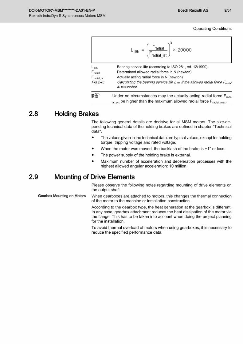
L10h Bearing service life (according to ISO 281, ed. 12/1990)Fradial Determined allowed radial force in N (newton)Fradial_ist Actually acting radial force in N (newton)Fig.2-6: Calculating the bearing service life L10h if the allowed radial force Fradial
is exceeded
Under no circumstances may the actually acting radial force Fradi‐
al_act be higher than the maximum allowed radial force Fradial_max.
2.8 Holding BrakesThe following general details are decisive for all MSM motors. The size-de‐pending technical data of the holding brakes are defined in chapter "Technicaldata".● The values given in the technical data are typical values, except for holding
torque, tripping voltage and rated voltage.● When the motor was moved, the backlash of the brake is ±1° or less.● The power supply of the holding brake is external.● Maximum number of acceleration and deceleration processes with the
highest allowed angular acceleration: 10 million.
2.9 Mounting of Drive ElementsPlease observe the following notes regarding mounting of drive elements onthe output shaft.
Gearbox Mounting on Motors When gearboxes are attached to motors, this changes the thermal connectionof the motor to the machine or installation construction.According to the gearbox type, the heat generation at the gearbox is different.In any case, gearbox attachment reduces the heat dissipation of the motor viathe flange. This has to be taken into account when doing the project planningfor the installation.To avoid thermal overload of motors when using gearboxes, it is necessary toreduce the specified performance data.
DOK-MOTOR*-MSM********-DA01-EN-P Rexroth IndraDyn S Synchronous Motors MSM
Bosch Rexroth AG 9/51
Operating Conditions

Fig.2-7: S1 characteristic of gearboxes
The torques indicated in the motor characteristics have to be re‐duced by approx. 10-20% when gearboxes are attached.
Observe all other notes and requirements contained in the documentation onthe gearboxes used.
Redundant Bearings When mounting drive elements, avoid redundant bearing, because indispens‐ably existing tolerances lead to additional forces onto the bearing of the motorshaft and if so lead to a significantly reduced bearing lifetime.
If redundant attachment cannot be avoided, it is absolutely neces‐sary that you consult Bosch Rexroth.
Couplings The machine construction and the attachment elements used must be carefullyadapted to the motor type so that the load limits of shaft and bearing are notexceeded.
When connecting extremely stiff couplings, the radial force whichconstantly changes the angular position may cause an impermis‐sibly high load on the shaft and bearing.
Bevel Gear Pinion or Helical GearDrive
Owing to thermal effects, the flange-sided end of the output shaft may shift by0.6 mm in relation to the motor housing. If helical drive pinions or bevel gearpinions directly attached to the output shaft are used, this change in positionwill lead to● a shift in the position of the axis, if the driving pinions are not defined axially
on the machine side,● a thermally dependent component of the axial force, if the driving pinions
are defined axially on the machine side. This causes the risk of exceedingthe maximum permissible axial force or of the play within the gears in‐creasing to an impermissible degree.
● damage of the motor bearing on the B-side due to exceeding of the max‐imum permissible axial force.
In such cases, drive elements should preferably be used with theirown bearings which are connected to the motor drive shaft via ax‐ially compensating couplings.
Bosch Rexroth AG DOK-MOTOR*-MSM********-DA01-EN-P Rexroth IndraDyn S Synchronous Motors MSM
10/51
Operating Conditions

2.10 Certifications Declaration of Conformity Declarations of conformity (refer to chapter 11 "Appendix" on page 47) con‐
firm that the components comply with the valid EN standards and EC directives.MSM motors
CE conformity regardingEN 60034-1: Rotating electrical maschines - Part 1: Dimensioning and operating be‐havior (IEC 60034-1:2004); German version EN 60034-1:2004EN 60034-5: Rotating electrical maschines - Part 5: Degrees of protection due to totalconstruction of rotating electrical machines (IP-cod) - classification (IEC 60034-5:2000+ Corrigendum 2001 + A1:2006); German version EN 60034-5:2001 + A1:2007
C-UR-US Listing The motors are listed by UL ("Underwriters Laboratories Inc.®"). You can findthe evidence of certification on the Internet under http://www.ul.com under"Certifications" by entering the file number or the "Company Name: Rexroth".MSM motors
Company NameBOSCH REXROTH ELECTRIC DRIVES & CONTROLS GMBHCategory Name:Power Conversion Equipment
For file numbers, norms and standards refer to the table in "Technical Data"
Wiring material UL (ready-made cables of Rexroth)In the scope of CSA / UL, use copper 60/75 °C only; class 6 orequivalent only.
Allowed pollution degreeComply with the allowed pollution degree of the components (see"Ambient and Operating Conditions").
CCC (China Compulsory Certifica‐
tion)The CCC test symbol comprises a compulsory certification of safety and qualityfor certain products mentioned in the product catalog "First Catalogue of Prod‐ucts Subject to Compulsory Certification" and in the CNCA document "Appli‐cation Scope for Compulsory Certification of Products acc. first Catalogue" andput in circulation in China. This compulsory certification has been existing since2003.
DOK-MOTOR*-MSM********-DA01-EN-P Rexroth IndraDyn S Synchronous Motors MSM
Bosch Rexroth AG 11/51
Operating Conditions
CNCA is the Chinese authority responsible for certification directives. When aproduct is imported in China, the certification will be checked at the customs bymeans of entries in a database. For the requirement of certification three criteriaare normally relevant:1. Customs tariff number (HS code) according to CNCA document "Appli‐
cation Scope for Compulsory Certification of Products acc. first Cata‐logue".
2. Scope of application according to CNCA document "Application Scope forCompulsory Certification of Products acc. first Catalogue".
3. For the IEC product standard used, the corresponding Chinese GB stand‐ard must exist.
For the Rexroth drive components described in this documentation, Rexrothcertification is not required at present, thus they are not CCC certified. Negativecertifications will not be issued.
Bosch Rexroth AG DOK-MOTOR*-MSM********-DA01-EN-P Rexroth IndraDyn S Synchronous Motors MSM
12/51
Operating Conditions
3 Identification and Type Code3.1 Identification
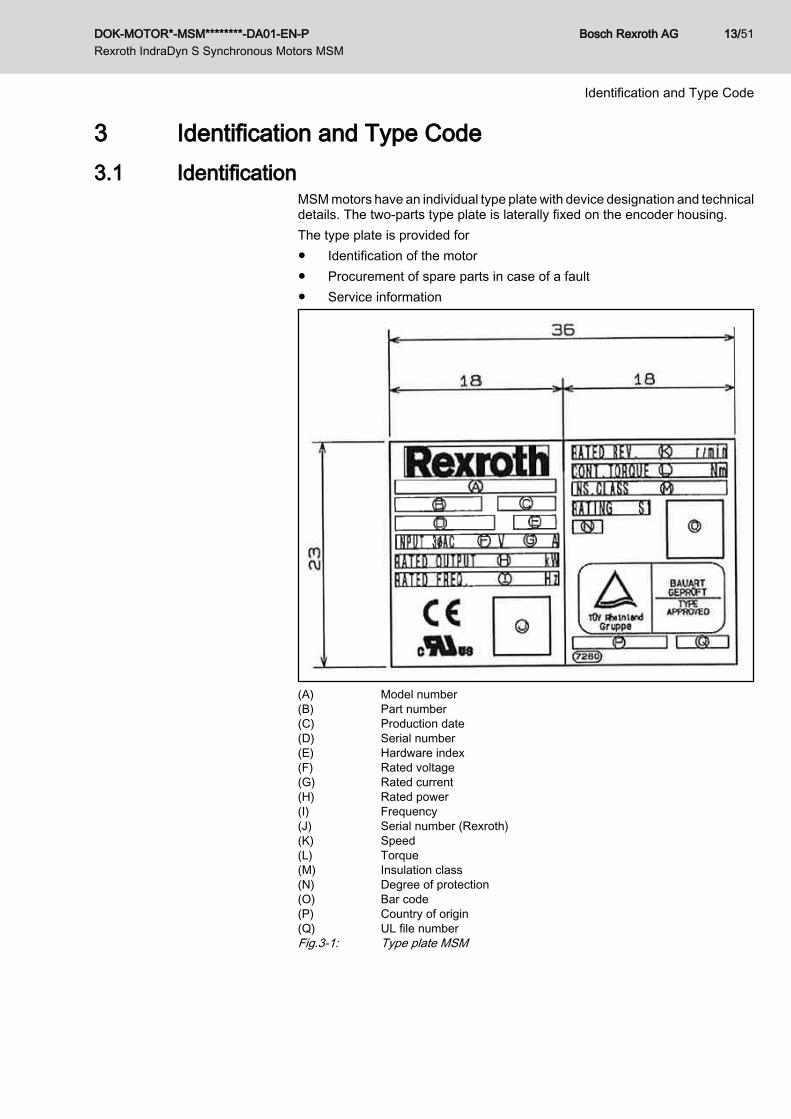
MSM motors have an individual type plate with device designation and technicaldetails. The two-parts type plate is laterally fixed on the encoder housing.The type plate is provided for● Identification of the motor● Procurement of spare parts in case of a fault● Service information
(A) Model number(B) Part number(C) Production date(D) Serial number(E) Hardware index(F) Rated voltage(G) Rated current(H) Rated power(I) Frequency(J) Serial number (Rexroth)(K) Speed(L) Torque(M) Insulation class(N) Degree of protection(O) Bar code(P) Country of origin(Q) UL file numberFig.3-1: Type plate MSM
DOK-MOTOR*-MSM********-DA01-EN-P Rexroth IndraDyn S Synchronous Motors MSM
Bosch Rexroth AG 13/51
Identification and Type Code

3.2 Type Code MSM019The following figure illustrates the basic structure of the type code.Our sales representative will help you with the current status ofavailable versions.
Fig.3-2: MSM019
Bosch Rexroth AG DOK-MOTOR*-MSM********-DA01-EN-P Rexroth IndraDyn S Synchronous Motors MSM
14/51
Identification and Type Code
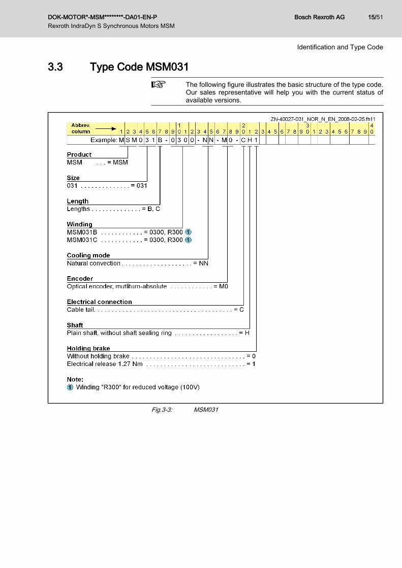
3.3 Type Code MSM031The following figure illustrates the basic structure of the type code.Our sales representative will help you with the current status ofavailable versions.
Fig.3-3: MSM031
DOK-MOTOR*-MSM********-DA01-EN-P Rexroth IndraDyn S Synchronous Motors MSM
Bosch Rexroth AG 15/51
Identification and Type Code

3.4 Type Code MSM041The following figure illustrates the basic structure of the type code.Our sales representative will help you with the current status ofavailable versions.
Fig.3-4: MSM041
Bosch Rexroth AG DOK-MOTOR*-MSM********-DA01-EN-P Rexroth IndraDyn S Synchronous Motors MSM
16/51
Identification and Type Code
4 Technical Data4.1 Basic Principles4.1.1 Operation Modes
The motors are documented according to the test criteria and measuring meth‐ods of EN 60034-1. The specified characteristics correspond to operationmodes S1.
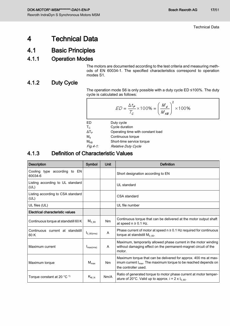
4.1.2 Duty CycleThe operation mode S6 is only possible with a duty cycle ED ≤100%. The dutycycle is calculated as follows:
ED Duty cycleTC Cycle durationΔTP Operating time with constant loadMd Continuous torqueMKB Short-time service torqueFig.4-1: Relative Duty Cycle
4.1.3 Definition of Characteristic Values
Description Symbol Unit Definition
Cooling type according to EN60034-6 Short designation according to EN
Listing according to UL standard(UL) UL standard
Listing according to CSA standard(UL) CSA standard
UL files (UL) UL file number
Electrical characteristic values
Continuous torque at standstill 60 K M0_60 Nm Continuous torque that can be delivered at the motor output shaftat speed n ≥ 0.1 Hz.
Continuous current at standstill60 K
I0_60(rms) APhase current of motor at speed n ≥ 0.1 Hz required for continuoustorque at standstill M0_60.
Maximum current Imax(rms) AMaximum, temporarily allowed phase current in the motor windingwithout damaging effect on the permanent-magnet circuit of themotor.
Maximum torque Mmax NmMaximum torque that can be delivered for approx. 400 ms at max‐imum current Imax. The maximum torque to be reached depends onthe controller used.
Torque constant at 20 °C 1) KM_N Nm/ARatio of generated torque to motor phase current at motor temper‐ature of 20°C. Valid up to approx. i = 2 x I0_60.
DOK-MOTOR*-MSM********-DA01-EN-P Rexroth IndraDyn S Synchronous Motors MSM
Bosch Rexroth AG 17/51
Technical Data
Description Symbol Unit Definition
Constant voltage at 20 °C 2) KEMK_1000 V/min-1 R.m.s. value of the induced motor voltage at motor temperature20 °C and 1000 revolutions per minute.
Winding resistance at 20 °C R12 ohm Measured winding resistance between two winding ends.
Winding inductance L12 mH Measured inductance between two phases.
Leakage capacitance of the com‐ponent
Cab nF Leakage capacitance
Number of pole pairs p - Number of pole pairs
Mechanical characteristic values
Rotor inertia Jrot kg*m2 Inertia of rotor without optional holding brake.
Power wire cross section A60Minimum cross section of power wire of power cable to be connec‐ted to motor
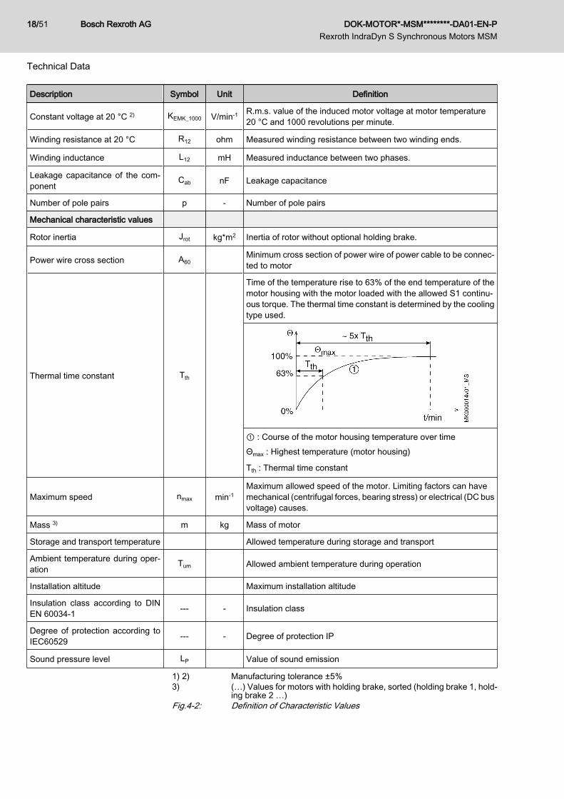
Thermal time constant Tth
Time of the temperature rise to 63% of the end temperature of themotor housing with the motor loaded with the allowed S1 continu‐ous torque. The thermal time constant is determined by the coolingtype used.
① : Course of the motor housing temperature over timeΘmax : Highest temperature (motor housing)
Tth : Thermal time constant
Maximum speed nmax min-1Maximum allowed speed of the motor. Limiting factors can havemechanical (centrifugal forces, bearing stress) or electrical (DC busvoltage) causes.
Mass 3) m kg Mass of motor
Storage and transport temperature Allowed temperature during storage and transport
Ambient temperature during oper‐ation
Tum Allowed ambient temperature during operation
Installation altitude Maximum installation altitude
Insulation class according to DINEN 60034‑1 --- - Insulation class
Degree of protection according toIEC60529 --- - Degree of protection IP
Sound pressure level LP Value of sound emission
1) 2) Manufacturing tolerance ±5%3) (…) Values for motors with holding brake, sorted (holding brake 1, hold‐
ing brake 2 …)Fig.4-2: Definition of Characteristic Values
Bosch Rexroth AG DOK-MOTOR*-MSM********-DA01-EN-P Rexroth IndraDyn S Synchronous Motors MSM
18/51
Technical Data

4.2 MSM0194.2.1 Technical Data MSM019
Description Symbol UnitMSM019A-0300-NN
preliminaryMSM019B-0300-NN
preliminary
Cooling type according to EN60034-6 - IC00
Listing according to UL standard(UL) - UL 1004; ANSI UL 840
Listing according to CSA standard(UL) - CSA-C22.2 No. 100
UL files (UL) E223837
Electrical characteristic values
Continuous torque at standstill 60 K M0_60 Nm 0.16 0.32
Continuous current at standstill60 K
I0_60(rms) A 1.10
Maximum current Imax(rms) A 3.30
Maximum torque Mmax Nm 0.48 0.95
Torque constant at 20 °C 1) KM_N Nm/A 0.14 0.30
Constant voltage at 20 °C 2) KEMK_1000 V/min-1 8.6 17.4
Winding resistance at 20 °C R12 ohm 9.30 13.20
Winding inductance L12 mH 5.650 9.250
Leakage capacitance of the com‐ponent
Cab nF 0.3 0.7
Number of pole pairs p - 4
Mechanical characteristic values
Rotor inertia Jrot kg*m2 0.0000025 0.00001
Power wire cross section A60 mm2 0.75
Thermal time constant Tth min tbd
Maximum speed nmax min-1 5,000
Mass 3) m kg 0.32 (0.53) 0.47 (0.68)
Storage and transport temperature TL °C -20 ... +60
Ambient temperature during oper‐ation
Tum °C 0 ... 40
Installation altitude m 0 ... 1,000
Insulation class according to DINEN 60034‑1 --- - 130 (B)
Last modification: 2008-11-20
DOK-MOTOR*-MSM********-DA01-EN-P Rexroth IndraDyn S Synchronous Motors MSM
Bosch Rexroth AG 19/51
Technical Data

Description Symbol UnitMSM019A-0300-NN
preliminaryMSM019B-0300-NN
preliminary
Degree of protection according toIEC60529 --- - IP54
Sound pressure level LP dB[A] tbd
Last modification: 2008-11-20
1) 2) Manufacturing tolerance ±5%3) (...) Values for motors with holding brake, sorted (holding brake 1, hold‐
ing brake 2 ...)Fig.4-3: Technical data MSM
Description Symbol Unit Holding brake 1 (MSM019)
Holding torque M4 Nm 0.29
Rated voltage UN V 24 ± 1.2
Rated current IN A 0.3
Clamping delay t1 ms 35
Release delay t2 ms 20
Inertia brake Jrot kg*m2 0.0000002
Last modification: 2008-10-16
Fig.4-4: MSM019 Holding Brakes - Technical Data (Optional)Status of the Characteristic Curve: preliminary
① Mmax IndraDrive Cs, supply 3 * 230 V② Mmax IndraDrive Cs, supply 3 * 100 V -10%Fig.4-5: Torque-Speed Characteristic
Bosch Rexroth AG DOK-MOTOR*-MSM********-DA01-EN-P Rexroth IndraDyn S Synchronous Motors MSM
20/51
Technical Data

Status of the Characteristic Curve: preliminary
① Mmax IndraDrive Cs, supply 3 * 230 VFig.4-6: Torque-Speed Characteristic
4.2.2 Dimensions MSM019
Motor A B C D E F G H K L M N
MSM019A-...-..-..CH0 38 72 25 ø8h6 ø30h7 ø45±0.20 ø3.5 51 20.8 27 3 6
MSM019A-...-..-..CH1 38 102 25 ø8h6 ø30h7 ø45±0.20 ø3.5 51 20.8 27 3 6
MSM019B-...-..-..CH0 38 92 25 ø8h6 ø30h7 ø45±0.20 ø3.5 51 40.8 27 3 6
MSM019B-...-..-..CH1 38 122 25 ø8h6 ø30h7 ø45±0.20 ø3.5 51 40.8 27 3 6
Fig.4-7: Dimensions MSM019
DOK-MOTOR*-MSM********-DA01-EN-P Rexroth IndraDyn S Synchronous Motors MSM
Bosch Rexroth AG 21/51
Technical Data

4.3 MSM0314.3.1 Technical Data MSM031
Description Symbol UnitMSM031B-0300-NN
preliminaryMSM031C-0300-NN
preliminary
Cooling type according to EN60034-6 - IC00
Listing according to UL standard(UL) - UL 1004; ANSI UL 840
Listing according to CSA standard(UL) - CSA-C22.2 No. 100 CSA-C22.2 No. 100
UL files (UL) E223837
Electrical characteristic values
Continuous torque at standstill 60 K M0_60 Nm 0.64 1.30
Continuous current at standstill60 K
I0_60(rms) A 1.60 2.60
Maximum current Imax(rms) A 4.90 7.70
Maximum torque Mmax Nm 1.91 3.80
Torque constant at 20 °C 1) KM_N Nm/A 0.41 0.51
Constant voltage at 20 °C 2) KEMK_1000 V/min-1 24.5 30.6
Winding resistance at 20 °C R12 ohm 6.10 3.60
Winding inductance L12 mH 14.700 10.600
Leakage capacitance of the com‐ponent
Cab nF 0.7 1.4
Number of pole pairs p - 4
Mechanical characteristic values
Rotor inertia Jrot kg*m2 0.00001 0.00003
Power wire cross section A60 mm2 0.75
Thermal time constant Tth min tbd
Maximum speed nmax min-1 5,000
Mass 3) m kg 0.82 ( 1.3 ) 1.2 ( 1.7 )
Storage and transport temperature TL °C -20 ... +60
Ambient temperature during oper‐ation
Tum °C 0 ... 40
Installation altitude m 0 ... 1,000
Insulation class according to DINEN 60034‑1 --- - 130 (B)
Last modification: 2008-11-20
Bosch Rexroth AG DOK-MOTOR*-MSM********-DA01-EN-P Rexroth IndraDyn S Synchronous Motors MSM
22/51
Technical Data

Description Symbol UnitMSM031B-0300-NN
preliminaryMSM031C-0300-NN
preliminary
Degree of protection according toIEC60529 --- - IP54
Sound pressure level LP dB[A] tbd
Last modification: 2008-11-20
1) 2) Manufacturing tolerance ±5%3) (...) Values for motors with holding brake, sorted (holding brake 1, hold‐
ing brake 2 ...)Fig.4-8: MSM031B-0300-NN, MSM031C-0300-NN
Description Symbol Unit Holding brake 1 (MSM031)
Holding torque M4 Nm 1.27
Rated voltage UN V 24 ± 1.2
Rated current IN A 0.36
Clamping delay t1 ms 50
Release delay t2 ms 15
Inertia brake Jrot kg*m2 0.0000018
Last modification: 2008-10-16
Fig.4-9: MSM031 Holding Brakes - Technical Data (Optional)Status of the Characteristic Curve: preliminary
① Mmax IndraDrive Cs, supply 3 * 230 V② Mmax IndraDrive Cs, supply 3 * 200 V -10%Fig.4-10: Torque-Speed Characteristic
DOK-MOTOR*-MSM********-DA01-EN-P Rexroth IndraDyn S Synchronous Motors MSM
Bosch Rexroth AG 23/51
Technical Data
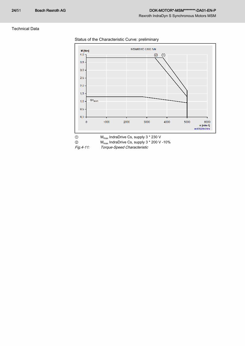
Status of the Characteristic Curve: preliminary
① Mmax IndraDrive Cs, supply 3 * 230 V② Mmax IndraDrive Cs, supply 3 * 200 V -10%Fig.4-11: Torque-Speed Characteristic
Bosch Rexroth AG DOK-MOTOR*-MSM********-DA01-EN-P Rexroth IndraDyn S Synchronous Motors MSM
24/51
Technical Data

4.3.2 Dimensions MSM031
Motor A B C D E F G H K L M N
MSM031B-...-..-..CH0 60 79 30 ø11h6 ø50h7 ø70±0.20 ø4.5 71 22.5 36 3 6.5
MSM031B-...-..-..CH1 60 115.5 30 ø11h6 ø50h7 ø70±0.20 ø4.5 71 22.5 36 3 6.5
MSM031C-...-..-..CH0 60 98.5 30 ø14h6 ø50h7 ø70±0.20 ø4.5 71 42 36 3 6.5
MSM031C-...-..-..CH1 60 135 30 ø14h6 ø50h7 ø70±0.20 ø4.5 71 42 36 3 6.5
Fig.4-12: Dimensions MSM031
DOK-MOTOR*-MSM********-DA01-EN-P Rexroth IndraDyn S Synchronous Motors MSM
Bosch Rexroth AG 25/51
Technical Data

4.4 MSM0414.4.1 Technical Data MSM041
Description Symbol UnitMSM041B-0300-NN
preliminary
Cooling type according to EN60034-6 - IC00
Listing according to UL standard(UL) - UL 1004; ANSI UL 840
Listing according to CSA standard(UL) - CSA-C22.2 No. 100
UL files (UL) E223837
Electrical characteristic values
Continuous torque at standstill 60 K M0_60 Nm 2.40
Continuous current at standstill60 K
I0_60(rms) A 4.00
Maximum current Imax(rms) A 12.00
Maximum torque Mmax Nm 7.10
Torque constant at 20 °C 1) KM_N Nm/A 0.64
Constant voltage at 20 °C 2) KEMK_1000 V/min-1 37.6
Winding resistance at 20 °C R12 ohm 1.50
Winding inductance L12 mH 6.700
Leakage capacitance of the com‐ponent
Cab nF 1.3
Number of pole pairs p - 4
Mechanical characteristic values
Rotor inertia Jrot kg*m2 0.00009
Power wire cross section A60 mm2 0.75
Thermal time constant Tth min tbd
Maximum speed nmax min-1 4,500
Mass 3) m kg 2.3 ( 3.1 )
Storage and transport temperature TL °C -20 ... +60
Ambient temperature during oper‐ation
Tum °C 0 ... 40
Installation altitude m 0 ... 1,000
Insulation class according to DINEN 60034‑1 --- - 130 (B)
Last modification: 2008-11-05
Bosch Rexroth AG DOK-MOTOR*-MSM********-DA01-EN-P Rexroth IndraDyn S Synchronous Motors MSM
26/51
Technical Data

Description Symbol UnitMSM041B-0300-NN
preliminary
Degree of protection according toIEC60529 --- - IP54
Sound pressure level LP dB[A] tbd
Last modification: 2008-11-05
1) 2) Manufacturing tolerance ±5%3) (...) Values for motors with holding brake, sorted (holding brake 1, hold‐
ing brake 2 ...)Fig.4-13: MSM041B-0300-NN
Description Symbol Unit Holding brake 1 (MSM041)
Holding torque M4 Nm 2.45
Rated voltage UN V 24 ± 1.2
Rated current IN A 0.42
Clamping delay t1 ms 70
Release delay t2 ms 20
Inertia brake Jrot kg*m2 0.0000075
Last modification: 2008-10-16
Fig.4-14: MSM041 Holding Brakes - Technical Data (Optional)Status of the Characteristic Curve: preliminary
① Mmax IndraDrive Cs, supply 3 * 230 V② Mmax IndraDrive Cs, supply 3 * 200 V -10%Fig.4-15: Torque-Speed Characteristic
DOK-MOTOR*-MSM********-DA01-EN-P Rexroth IndraDyn S Synchronous Motors MSM
Bosch Rexroth AG 27/51
Technical Data
4.4.2 Dimensions MSM041
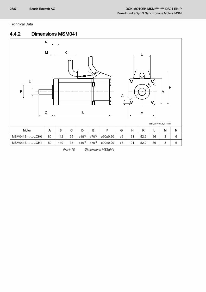
Motor A B C D E F G H K L M N
MSM041B-...-..-..CH0 80 112 35 ø19h6 ø70h7 ø90±0.20 ø6 91 52.2 36 3 6
MSM041B-...-..-..CH1 80 149 35 ø19h6 ø70h7 ø90±0.20 ø6 91 52.2 36 3 6
Fig.4-16: Dimensions MSM041
Bosch Rexroth AG DOK-MOTOR*-MSM********-DA01-EN-P Rexroth IndraDyn S Synchronous Motors MSM
28/51
Technical Data

5 Motor Encoder
Data Sheet - Encoder
Description Symbol Unit GEBER-M0 (MSM)
Battery box No Yes
Encoder design Singleturn - absolute Multiturn - absolute
Distinguishable revolutions 1 65,536
Incremental signals Without
Encoder resolution 17bit 17 + 16bit
System accuracy '' ±120
Encoder accuracy differential '' ±40
Encoder accuracy integral '' ±80
Maximum encoder speed min-1 6,000
Supply voltageVCCEncod‐
erV 4.75 … 5.25
Max. current consumption IEncoder mA 70
Last modification: 2009-07-07
'' Angular secondsFig.5-1: Encoder Data
Singleturn Absolute Value Encoder The singleturn absolute value encoder is used for absolute indirect positiondetection within 1 motor revolution.
The absolute axis position is lost after de-energization with this en‐coder variant.
Multiturn Absolute Value Encoder The multiturn absolute value encoder is used for absolute indirect position de‐
tection within 65,536 motor revolutions. It replaces a separate absolute valueencoder at the motor.
With this encoder type, the absolute axis position is maintained dueto its battery backup, even after the voltage has been switched off.When the motor is separated from the battery box, the informationon the absolute axis position gets lost after approx. 1 minute.
Details for Multiturn Signals To use the multiturn-option, a buffer storage over an external battery is neces‐sary. Therefore, the following accessory is available:SUP-E01_MSM_BATTERYBOXSUP_E03_DKC*CS-BATTRY
Service Life of the Encoder When the MSM encoders are operated within the specified limiting data (am‐bient temperature: max. 70 °C, nominal speed 3,000 min-1, …), the nominalbearing service life is:L10h = 20,000 operating hours
DOK-MOTOR*-MSM********-DA01-EN-P Rexroth IndraDyn S Synchronous Motors MSM
Bosch Rexroth AG 29/51
Motor Encoder

Bosch Rexroth AG DOK-MOTOR*-MSM********-DA01-EN-P Rexroth IndraDyn S Synchronous Motors MSM
30/51

6 Connection System6.1 Connection for Power and Encoder
The connections for power and encoder of the MSM motors is made via flexibleconnection cables with connector (IP 54) and bayonet lock.When connecting the connection cables, the bayonet lock must engage.
Fig.6-1: MSM motor connectionFor the length of the flexible connection cable, refer to the following table.
MotorLength connection cable and connector
Performance ① Encoder ②
MSM019 200 mm (+70 mm connec‐tor INS0757)
230 mm (+63 mm connec‐tor INS0758)
MSM031 200 mm (+70 mm connec‐tor INS0757)
220 mm (+63 mm connec‐tor INS0758)
MSM041 200 mm (+70 mm connec‐tor INS0757)
220 mm (+63 mm connec‐tor INS0758)
Fig.6-2: MSM Motors: Connection Cable Length
DOK-MOTOR*-MSM********-DA01-EN-P Rexroth IndraDyn S Synchronous Motors MSM
Bosch Rexroth AG 31/51
Connection System

6.2 Pin AssignmentPower Connection
Br Motor holding brake (can be ordered optionally, see type code)Fig.6-3: MSM Power Connection
Bosch Rexroth AG DOK-MOTOR*-MSM********-DA01-EN-P Rexroth IndraDyn S Synchronous Motors MSM
32/51
Connection System

Encoder Connection
Batterybox necessary for multiturn-operation; not necessary for singleturn-opera‐tion
Fig.6-4: MSM Encoder Connection
DOK-MOTOR*-MSM********-DA01-EN-P Rexroth IndraDyn S Synchronous Motors MSM
Bosch Rexroth AG 33/51
Connection System

6.3 Ready-Made Connection Cable6.3.1 Power CableOverview
SelectionPower cable for 60K motor operation without fan unit 1)
HCS01.1E-…
MSM W0003 W0006 W0009 W0013 W0005 W0008 W0018 W0028
MSM019A
RKL0013(RKL0035 extension optional)
- -
MSM019B - -
MSM031B - -
MSM031C - -
MSM041B - -
W0003 W0006 W0009 W0013 W0005 W0008 W0018 W0028
1) Motor operation with fan unit see cable selection DOK-CONNEC-CA‐BLE*INDRV-CAxx-xx-x
- Not possibleFig.6-5: Power cable for converter HCS01 and MSM motors
Bosch Rexroth AG DOK-MOTOR*-MSM********-DA01-EN-P Rexroth IndraDyn S Synchronous Motors MSM
34/51
Connection System

Interconnection diagram
Interconnection diagram RKL0013
Interconnection diagram RKL0035
Technical Data of the CablesData Sheet - Bulk Cable
Description Symbol Unit INK0670
Brief description of cable [4x0.75mm² + (2x0.5mm²)StC]C
RoHS
UL recognized (UL) UL and CSA
UL files (UL)
AWM style (UL)
Diameter mm 10.0 +/-0.4
Cross section of power wire mm2 0.75
Material of cable jacket1) PUR
Color of cable jacket RAL 2003 (orange)
Specific cable weight m kg/m 0.132
Temperature range for storage °C -30°C to +40°C
Last modification: 2009-06-05
DOK-MOTOR*-MSM********-DA01-EN-P Rexroth IndraDyn S Synchronous Motors MSM
Bosch Rexroth AG 35/51
Connection System
Description Symbol Unit INK0670
Ambient temperature at operation(permanent installation) °C -30°C to +40°C
Ambient temperature at operation(flexible installation) °C -20°C to +40°C
Operating temperature at conduc‐tor (flexible/permanent) °C +80°C
Specific capacitance CY_K_typ
Conductor resistance at 20°C (EN60228; class 6)
R20 ohm/km Acc. to VDE 0295 class 6
Operational voltage at power wires V 300/500V (VDE); 600V/AC 80° (CUL)
Operational voltage at control wires V 300/300V (VDE); 600V/AC 80° (CUL)
Suitable for application in flexiblecable tracks Yes
Bending cycles2) mio. Min. 5,000,000
Bending radius with flexible instal‐lation mm 7.5 x AD
Bending radius with permanent in‐stallation mm 5 x AD
Halogens Halogen-free
Oil resistance Acc. to DIN EN 60 811-2-1
FlammabilityUL 758, section 40, Cable Flame Test Section 1061 acc. to UL 1581
and CSA C22.2 No. 210-05 Sec. 8.8.2 test acc. to DIN EN60332-1-2
Last modification: 2009-06-05
1) Acc. to DIN EN 50363-10-22) Acceleration up to 10 m/s2; velocity up to 10 m/s; travel up to 50 mFig.6-6: INK - Technical Data
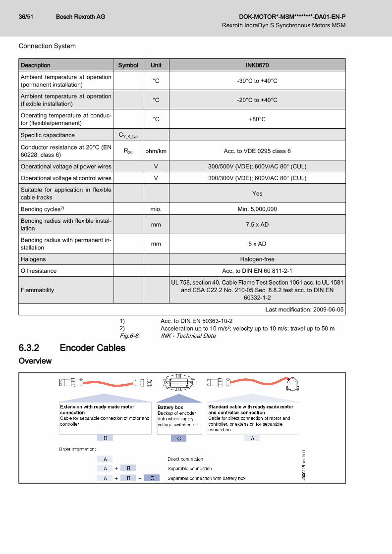
6.3.2 Encoder CablesOverview
Bosch Rexroth AG DOK-MOTOR*-MSM********-DA01-EN-P Rexroth IndraDyn S Synchronous Motors MSM
36/51
Connection System
Selection
HCS01.1E-…
MSM W0003 W0006 W0009 W0013 W0005 W0008 W0018 W0028
MSM019A
RKG0033(RKG0034 extension optional)
- -
MSM019B - -
MSM031B - -
MSM031C - -
MSM041B - -
W0003 W0006 W0009 W0013 W0005 W0008 W0018 W0028
- Not possibleFig.6-7: Encoder Cable for Converter HCS01 and MSM Motors
Interconnection diagram
Interconnection diagram RKL0033
Interconnection diagram RKL0034
DOK-MOTOR*-MSM********-DA01-EN-P Rexroth IndraDyn S Synchronous Motors MSM
Bosch Rexroth AG 37/51
Connection System

Technical Data of the CablesData Sheet - Bulk Cable
Description Symbol Unit INK0448
Brief description of cable (4x2x0.25mm² + 2x0.5mm²)C
RoHS conform acc. to EU directive 2002/95/EG
UL recognized (UL) UR, cUR
UL files (UL) E140404; E42256; E73526
AWM style (UL) 20233, 20235
Diameter mm 8.8 +/-0.3
Cross-section of control wire mm2 0.25
Material of cable jacket1) PUR (weakly adhesive, matt)
Color of cable jacket RAL 2003 (orange)
Specific cable weight m kg/m 0.100
Temperature range for storage °C -30°C to +40°C
Ambient temperature at operation(permanent installation) °C -30°C to +40°C
Ambient temperature at operation(flexible installation) °C -20°C to +40°C
Operating temperature at conduc‐tor (flexible/permanent) °C +80°C / +90°C
Conductor resistance at 20°C (EN60228; class 6)
R20 ohm/km 83.0 (0.25 mm²) / 39.5 (0.5mm²)
Operational voltage at control wires V 300/300V (VDE); 300V/AC (UL)
Suitable for application in flexiblecable tracks Yes
Bending cycles2) mio. 5
Bending radius with flexible instal‐lation mm 7.5 x D
Bending radius with permanent in‐stallation mm 5 x D
Halogens Halogen-free
Oil resistance DIN EN 60 811-2-1 and HD 22.10 appendix A
FlammabilityUL 758, section 40, Cable Flame Test Section 1061 acc. to UL 1581
and CSA C22.2 No. 210-05 Sec. 8.8.2 test acc. to DIN EN60332-1-2
Last modification: 2009-06-05
1) Acc. to DIN EN 50363-10-22) Acceleration up to 10 m/s2; velocity up to 10 m/s; travel up to 50 mFig.6-8: INK - Technical Data
Bosch Rexroth AG DOK-MOTOR*-MSM********-DA01-EN-P Rexroth IndraDyn S Synchronous Motors MSM
38/51
Connection System

7 Transport and Storage7.1 Transport of the Motors
Ambient and Operating Conditions - Transport
Description Symbol Unit Value
Temperature range Ta_tran °C -20 … +80
Relative humidity % 5 … 95
Absolute humidity g/m3 1 … 60
Climatic category (IEC721) 2K3
Moisture condensation Not allowed
Icing Not allowed
Fig.7-1: Ambient and Operating Conditions - Transport
7.2 Storage of the MotorsAmbient and Operating Conditions - Storage
Description Symbol Unit Value
Temperature range Ta_store °C -20 … +60
Relative humidity % 5 … 95
Absolute humidity g/m3 1 … 29
Climatic category (IEC721) 1K3
Moisture condensation Not allowed
Icing Not allowed
Fig.7-2: Ambient and Operating Conditions - Storage
DOK-MOTOR*-MSM********-DA01-EN-P Rexroth IndraDyn S Synchronous Motors MSM
Bosch Rexroth AG 39/51
Transport and Storage

Bosch Rexroth AG DOK-MOTOR*-MSM********-DA01-EN-P Rexroth IndraDyn S Synchronous Motors MSM
40/51

8 Assembly KitMounting Screws for Flange
Mounting
Fastening screws are not in the scope of delivery.
The motors must be professionally and safely fastened to the maschine. Usepan-head machine screws DIN 912 - M... x ... - 8.8 and the correspondingwashers according to DIN EN 28738 for motor fastening. For some motors, itis not necessary to use washers, see table.
The screwed connections for flange assembly must be able to takeup both the force due to weight of the motor and the forces actingduring operation.
Recommended Screws for Flange Mounting of MSM Motors
B05 (flange assembly)
Hole Screw (8.8) WasherDIN EN 28738
Ø [mm] Type 1) MGA [Nm] Ø [mm]
MSM019 3.5 M3 x 16 1.3 None
MSM031 4.5 M4 x 20 3.1 None
MSM041 6.0 M5 x 20 6.1 None
① Mounting holeMGA Tightening torque in Newton meters1) Minimum screw length for screwing into steel.Fig.8-1: MSM Mounting Accessories (Flange Assembly)
If you use screws and washers different from the recommendedones, the property class of the screws and the hardness class ofthe washers must be equivalent to transmit the required tighteningtorques.
DOK-MOTOR*-MSM********-DA01-EN-P Rexroth IndraDyn S Synchronous Motors MSM
Bosch Rexroth AG 41/51
Assembly Kit

Bosch Rexroth AG DOK-MOTOR*-MSM********-DA01-EN-P Rexroth IndraDyn S Synchronous Motors MSM
42/51

9 Environmental Protection and Disposal9.1 Environmental Protection
Production Processes The products are made with energy- and resource-optimized production pro‐cesses which allow re-using and recycling the resulting waste. We regularly tryto replace pollutant-loaded raw materials and supplies by more environment-friendly alternatives.
Prohibited Substances We guarantee that our products include no substances according to the chem‐icals-ban-decree. We furthermore declare that our products are free of mercury,asbestos, PCB and chlorinated hydrocarbons.
No Release of Hazardous Substan‐ces
Our products do not contain any hazardous substances which may be releasedin the case of appropriate use. Normally, our products will not have any negativinfluences on the environment.
Significant Components Basically, our products contain the following components:Electronic devices Motors∙ Steel ∙ Steel∙ Aluminum ∙ Aluminum∙ Copper ∙ Copper∙ Synthetic materials ∙ Brass∙ Electronic components and modules ∙ Magnetic materials ∙ Electronic components and modules
9.2 DisposalReturn of Products Our products can be returned to our premises free of charge for disposal. It is
a precondition, however, that the products are free of oil, grease or other dirt.Furthermore, the products returned for disposal must not contain any undueforeign material or foreign components.Send the products ”free domicile” to the following address: Bosch Rexroth AG Electric Drives and Controls Buergermeister-Dr.-Nebel-Strasse 2 97816 Lohr am Main, Germany
Packaging The packaging materials consist of cardboard, wood and polystyrene. Thesematerials can be recycled anywhere without any problem.For ecological reasons, please refrain from returning the empty packages tous.
Recycling Most of the products can be recycled due to their high content of metal. In orderto recycle the metal in the best possible way, the products must be disassem‐bled into individual modules.Metals contained in electric and electronic modules can also be recycled bymeans of special separation processes. The synthetic materials remaining afterthese processes can be thermally recycled.If the products contain batteries or accumulators, these have to be removedbefore recycling and disposed of.
DOK-MOTOR*-MSM********-DA01-EN-P Rexroth IndraDyn S Synchronous Motors MSM
Bosch Rexroth AG 43/51
Environmental Protection and Disposal

Bosch Rexroth AG DOK-MOTOR*-MSM********-DA01-EN-P Rexroth IndraDyn S Synchronous Motors MSM
44/51

10 Service and SupportOur service helpdesk at out headquarters in Lohr, Germany, will assist you withall kinds of enquiries. Out of helpdesk hours please contact our German servicedepartment directly.
Helpdesk Service HotlineGermany
Service HotlineWorldwide
Time 1) Mo-Fr 7:00 am - 6:00 pm CET Mo-Fr 6:00 pm - 7:00 am CETSa-Su 0:00 am - 12:00 pm CET
Outwith Germany please con‐tact our sales/service office inyour area first.For hotline numbers refer to thesales office addresses on theInternet.
Phone +49 (0) 9352 40 50 60 +49 (0) 171 333 88 26or+49 (0) 172 660 04 06
Fax +49 (0) 9352 40 49 41 –
e-mail [email protected] –
Internet http://www.boschrexroth.comYou will also find additional notes regarding service, maintenance (e.g. delivery addresses) andtraining.
1) Central European Time (CET)
Preparing Information For quick and efficient help please have the following information ready:● detailed description of the fault and the circumstances● information on the type plate of the affected products, especially type co‐
des and serial numbers● your phone, fax numbers and e-mail address so we can contact you in
case of questions.
DOK-MOTOR*-MSM********-DA01-EN-P Rexroth IndraDyn S Synchronous Motors MSM
Bosch Rexroth AG 45/51
Service and Support

Bosch Rexroth AG DOK-MOTOR*-MSM********-DA01-EN-P Rexroth IndraDyn S Synchronous Motors MSM
46/51

11 Appendix
Fig.11-1: Declaration of conformity 1/2
DOK-MOTOR*-MSM********-DA01-EN-P Rexroth IndraDyn S Synchronous Motors MSM
Bosch Rexroth AG 47/51
Appendix

Fig.11-2: Declaration of conformity 2/2
Bosch Rexroth AG DOK-MOTOR*-MSM********-DA01-EN-P Rexroth IndraDyn S Synchronous Motors MSM
48/51
Appendix
IndexAAbsolute value encoder...................................... 29Accessories......................................................... 41Ambient conditions................................................ 5Assembly kit........................................................ 41
BBevel gear pinion................................................ 10Brake (holding brake)
Data ................................................................ 9
CCCC, China Compulsory Certification................. 11CE label.............................................................. 11Certifications....................................................... 11Compatibility
With foreign matters ....................................... 6Contained substances
see "Significant components" ....................... 43Coupling.............................................................. 10C-UR-US listing................................................... 11
DData
Motor MSM019 ............................................. 19Motor MSM031 ............................................. 22Motor MSM041 ............................................. 26
Declaration of conformity.................................... 11Derating vs. installation altitude
Overvoltage limiter ......................................... 6Duty cycle
Motor ............................................................ 17
EEncoder
Absolute value encoder ................................ 29Multiturn ....................................................... 29Singleturn ..................................................... 29
FFittings.................................................................. 9Flange assembly................................................. 41Flange mounting................................................. 41Foreign matters
Compatibility ................................................... 6
GGearbox ............................................................... 9Gear pinion......................................................... 10
HHazardous substances....................................... 43Helical teeth........................................................ 10Holding brake
Data ................................................................ 9
IIndraDyn S
Overview ........................................................ 3
LListing
C-UR-US ...................................................... 11
MMaterials
Motor .............................................................. 7Motor
Holding brake ................................................. 9Materials ......................................................... 7MSM019 ....................................................... 19MSM031 ....................................................... 22MSM041 ....................................................... 26Shaft ............................................................... 8Shaft load ....................................................... 8Technical data .............................................. 17
Motor mounting................................................... 41Mounting positions
Motors ............................................................ 7MSM
Certifications ................................................ 11Performance feature ...................................... 3
MSM019.............................................................. 19MSM031.............................................................. 22MSM041.............................................................. 26Multiturn.............................................................. 29
OOperating Conditions............................................ 5Operating conditions............................................. 5Operation modes
Motor ............................................................ 17Output shaft.......................................................... 8
Plain ............................................................... 8Overvoltage limiter
Derating vs. installation altitude ..................... 6
PPackaging........................................................... 43Production processes......................................... 43Prohibited substances......................................... 43
DOK-MOTOR*-MSM********-DA01-EN-P Rexroth IndraDyn S Synchronous Motors MSM
Bosch Rexroth AG 49/51
Index
RRedundant bearings............................................ 10Return of products.............................................. 43Rexroth IndraDyn S MSM
Introduction .................................................... 3Overview ........................................................ 3
SService Hotline.................................................... 45Shaft
Plain ............................................................... 8Shaft load.............................................................. 8Significant components....................................... 43Singleturn............................................................ 29Storage
Of the components ....................................... 39Support
see Service Hotline ...................................... 45
TTechnical data
Motor MSM019 ............................................. 19Motor MSM031 ............................................. 22Motor MSM041 ............................................. 26Motors .......................................................... 17
TTransport
Of the components ....................................... 39Type code
MSM019 ....................................................... 14MSM031 ....................................................... 15MSM041 ....................................................... 16
Type of construction.............................................. 7Types of installation.............................................. 7
UUL
Listing ........................................................... 11
Bosch Rexroth AG DOK-MOTOR*-MSM********-DA01-EN-P Rexroth IndraDyn S Synchronous Motors MSM
50/51
Index
R

Notes
DOK-MOTOR*-MSM********-DA01-EN-P Rexroth IndraDyn S Synchronous Motors MSM
Bosch Rexroth AG 51/51

Printed in GermanyDOK-MOTOR*-MSM********-DA01-EN-PR911329338
Bosch Rexroth AGElectric Drives and ControlsP.O. Box 13 5797803 Lohr, GermanyBgm.-Dr.-Nebel-Str. 297816 Lohr, GermanyTel. +49 (0)93 52-40-0Fax +49 (0)93 52-48 85www.boschrexroth.com