electric drives - justanswerv1_3.pdfthe ac drive incorporates a number of features and capabilities...
TRANSCRIPT
Copyright 2013 by Heinzmann GmbH & Co. KG. All rights reserved. This publication may not be reproduced by any means whatsoever or passed on to any third parties.
6455 Manual EA 12 006-e / 06-13
Heinzmann GmbH & Co. KG Electric Drives Am Haselbach 1 D-79677 Schönau Germany Phone +49 7673 8208 - 700 Fax +49 7673 8208 - 799 E-mail [email protected] www.heinzmann.com V.A.T. No.: DE145551926
HEINZMANN
Electric Drives
User Manual V 1.3
ACD xxxx Drive Motor controller for
brushless permanentmagnet Motor Generation 1

ACD xxx User Manual V 1.3
1
1 INTRODUCTION
1.1 ABOUT AC DRIVE DOCUMENTATION
1.1.1 THIS VERSION
This version replaces all previous versions of this document. We have made every effort to insure this document is complete and accurate at the time of printing. In accordance with our policy of continuing product improvement, all data in this document is subject to change or correction without prior notice.
1.1.2 SCOPE
This manual presents instructions, guidelines, diagram and other information relevant for installation and maintaining the AC Drive in an electrically powered vehicle utilizing the discrete I/O:s an/or CAN Bus and CANopen protocol for communications and control.
1.1.3 WARNING, CAUTION AND INFORMATION NOTICES
Special attention must be paid to the information presented in Warning, Caution and Information notices when they appear in this manual. Examples of Caution, Warning and Information notices along with an explanation of their purposes follow.
WARNING
A Warning informs the user of a hazard or potential hazard that could
result in serious of fatal injury if the precautions or instructions given in
the warning notice are not observed.
CAUTION
A Caution informs the user of a hazard or potential hazard that could
result in injury or damage to the equipment if the precautions or
instructions given in the caution notice are not observed. An Inion Box contains supplemental information or references to
supplemental infrmation on a topic.
i An information Box contains supplemental information or reference
to supplemental information on a topic
suppl
Stop Box highlights important conceptual or procedural details that must
be understood and applied in order to successfully use the product.
An Information
1.1.4 RELATED DOCUMENTS
Object Dictionary. The Object Dictionary provides important information about CANopen
communication with the AC Drive.

ACD xxx User Manual V 1.3
2
1.2 ABOUT THE AC DRIVE
1.2.1 PERSONAL SAFETY
HEINZMANN provides this and other manuals to assist manufacturers in using the AC Drive
in a correct, efficient and safe manner. Manufacturers must insure that all persons
responsible for the design and use of equipment employing the AC Drive have the proper
professional skill and apparatus knowledge.
WARNING
The high power levels and high torque available from a motor, AC Drive
combination can cause severe or fatal injury.
CAUTION
The AC Drive is intended for connection only to DC battery power sources
and for use with low voltage asynchronous motors.
Always verify before installation that the AC Drive model is correct for the
vehicle’s battery supply voltage. The DC Supply nominal voltage is stated on
a label on the cover of each AC Drive.
contains supplemental information or references to
1.2.2 OEM'S RESPONSIBILITY
Our AC Drive products are intended for controlling motors in battery powered electric
vehicles. These drives are supplied to original equipment manufacturers (OEMs) for
incorporation into their vehicles and vehicle control systems.
OEM's are responsible for ensuring that AC Drives are used for their intended purpose only,
safe function of the system and for compliance with all applicable regulations. Responsibility
for the safe functioning of the system reverts to the owner or user in all cases.
1.2.3 TECHNICAL SUPPORT
For additional information on any topic covered in this document, or for additional information
or application assistance contact HEINZMANN
1.2.4 REPAIR
Repair and testing of the AC Drive is available at: HEINZMANN
ACD xxx User Manual V 1.3
3
1.3 PRODUCT VARIANTS
1.3.1 CONFIGURATIONS
The AC Drive is manufactured in the following configuration.
Conduction cooled models (see Figure 1) with a flat heat sink and mounting surface
that transfers heat into the surrounding vehicle structure by conduction.
Volt range: 24/36/48/80 V.
Full functional control via discrete I/O:s or via CANbus.
Combinations are also possible.
Various I/O configurations for interfacing to the vehicle system.
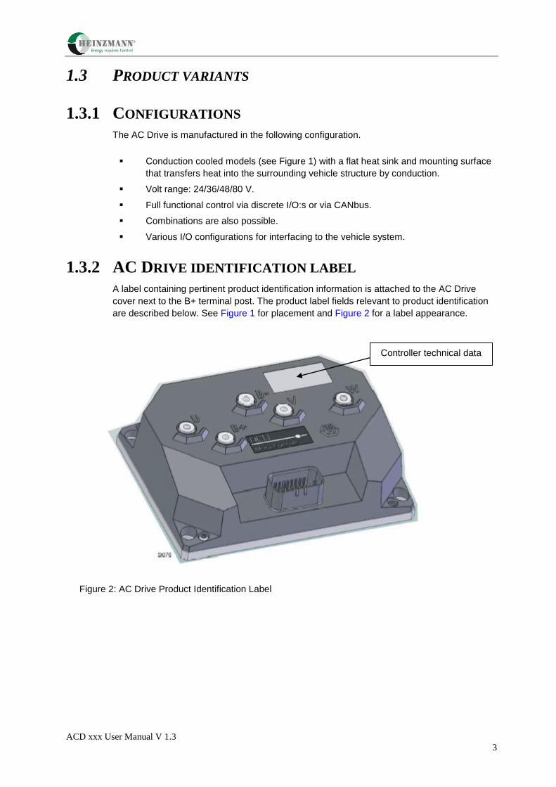
1.3.2 AC DRIVE IDENTIFICATION LABEL
A label containing pertinent product identification information is attached to the AC Drive
cover next to the B+ terminal post. The product label fields relevant to product identification
are described below. See Figure 1 for placement and Figure 2 for a label appearance.
Figure 2: AC Drive Product Identification Label
Controller technical data
ACD xxx User Manual V 1.3
4
1.4 STANDARD FEATURES OF THE AC DRIVE
The AC Drive incorporates a number of features and capabilities important to the electric
vehicle designer including:
Modern AC flux-vector control techniques for improved performance and operating
efficiency.
A family of drives covering a wide range of power outputs and battery voltages.
Programmable to match the characteristics of compatible induction or brushless PM
motors.
Designed for the environment of the electrically powered vehicle.
Closed loop speed regulator provides unequalled vehicle speed control when moving
and neutral braking for maintaining position when stopped.
Full four-quadrant operation - drive can directly accelerate or decelerate the motor in
both forward and reverse directions (no direction contactors required).
Regenerates dynamic braking energy down to zero speed.
Fully protected against under voltage, over voltage, over current and reverse polarity
and over temperature conditions.
Built-in neutral start (also called high pedal) protection prevents vehicle motion on
startup until drive sees a zero speed command.
CAN bus interface for safe and reliable networking in a vehiele control system.
Extended I/O:s for standalone applications.
Total software configurability eliminates all operator adjustments and assures
absolutely reproducible performance of identically configured AC Drives.
All heat generating components mounted on a massive heatsink whose temperature is
monitored.
Error/fault monitoring software implements necessary measures to prevent unsafe
operation if problems exist.
Warning/error codes and an error log provide informative and timely information for
diagnosis and elimination of problems.
Total user control over acceleration, braking and speed.

ACD xxx User Manual V 1.3
5
2 OVERVIEW OF A DRIVE SYSTEM
In a typical system (see Figure 3), one AC Drive directs the motion of a traction motor
coupled to the drive wheels. AC Drives convert DC power from the vehicle’s battery to three
phase AC power at the frequencies and currents necessary to drive their respective motors
as commanded.
Figure 3: Electrical Drive System
The main contactor, under control of the AC Drive, supplies battery power to the power
conversion section and removes battery power under certain error and fault conditions. An
external fuse protects the drive and cables against short circuit faults in the power
conversion section.
An internal PTC (Positive Temperature Coefficient) resistance limits inrush current to a bank
of filter capacitors when power is first turned on via the key start.
The key start contactor controls application of power to the control electronics section of the
AC Drive.
The motor provides feedback of its speed, direction and temperature to the AC Drive for
control and monitoring purposes. A speed sensor is integrated into the motor produces
speed and direction feedback signals and a temperature sensor (PTC resistance) embedded
in the stator winding provides an indication of motor temperature.
ACD xxx User Manual V 1.3
6
The AC Drive can be used as a standalone unit with all I/O signals (frw/rev, speed etc.)
connected direct to the AC Drive. Alternatively can the AC Drive be controlled via a truck
controller and CANBus.
The truck controller, based on input from operator controls and other criteria, transmits
speed, braking and other commands to the AC Drives over the CAN Bus. The truck
controller regularly monitors drive status and initiates corrective action upon recognition of a
warning/error condition.
When a fault/error condition warrants, the truck controller may open the main contactor,
removing battery power from the AC Drive power stage.
2.1 PRINCIPLES OF OPERATION
2.1.1 FUNCTIONAL DESCRIPTION
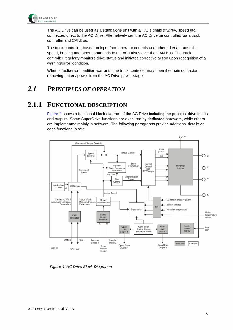
Figure 4 shows a functional block diagram of the AC Drive including the principal drive inputs
and outputs. Some SuperDrive functions are executed by dedicated hardware, while others
are implemented mainly in software. The following paragraphs provide additional details on
each functional block.
Figure 4: AC Drive Block Diagramm

ACD xxx User Manual V 1.3
7
2.1.2 CAN INTERFACE
The CAN Interface manages communications between the AC Drive and the CAN Bus. The
CAN controller provides the electrical interface and within the software the CANopen
protocol is handled.
2.1.3 SPEED CONTROL
The Speed Control accepts speed set points (Command Speed) as input and produces
torque commands (Torque Current) as output. It can function as a closed loop, proportional
or proportional plus integral, speed controller with feedback provided by the sensor bearing.
It includes provisions for limiting torque both in amplitude and derivate. It is also possible to
use advanced speed ramping functionality within the Speed Control block. The Speed
Control is implemented in software, with operating characteristics set by programmable
parameters.
2.1.4 CURRENT CONTROL AND SPWM-SYM
The dq-plane implemented current controller (so called vector control) controls the
magnetization current and the torque producing current independently of each other. The
software implemented Current Control is able to compensate for temperature and frequency
related changes in motor winding impedance as well as variations in the DC-supply voltage,
thereby providing precise control of motor flux and torque over a wide range of operating
conditions. The Current Control computes the required motor voltage, which is then realized
by SPWM-sym (Sinusoidal Pulse Width Modulation with summarization). The output from the
SPWM-sym block is the MOSFET gate pulses.
2.1.5 POWER CONVERSION SECTION
The principal drive output, a variable frequency, variable amplitude, three phase current, is
produced by the Power Conversion section from a DC power source. Figure 5 shows the
general circuit configuration. Depending on its current rating, an AC Drive may employ more
or less transistors than illustrated in Figure 5. During braking, regenerated energy from the
motor is returned to the battery.
All power components are mounted and thermally bonded to a large heatsink that forms one
surface of the drive. Heatsink temperature and DC supply voltage are sensed and monitored
for control and protection purposes.
Utilizing efficient MOSFET power transistors, the Power Conversion section amplifies three
PWM (Pulse Width Modulated) current commands supplied by the Current Regulator
producing three PWM voltages (see Figure 6). These PWM voltage waveforms, when
applied to the inductance of the stator, produce currents in the motor, which approximate
sine waves.

ACD xxx User Manual V 1.3
8
Figure 5: Power Conversion Section
Figure 6: Puls Width Modulation
During braking, the rotor runs at higher speed than the speed of the synchronous flux vector
and the motor functions as a generator, supplying power to the battery. The change from
motor to generator is smooth and instant when rotor speed exceeds synchronous speed.
The AC Drive supplies a magnetizing current at the proper frequency for optimum
regeneration performance.

ACD xxx User Manual V 1.3
9
The generated power is dependent on the slip (which the AC Drive controls). The transistors
functions as a 6-pulse rectifier (see Figure 7), converting the 3-phase AC current to DC-
current that charges the battery.
Figure 7: Current Flow During Regenaration
2.1.6 SPEED SENSOR INTERFACE
The Speed Sensor Interface converts the quadrature signal outputs from a sensor to digital
speed and direction numbers for use by the drive and system functions.
Alternatively, an analog sin/cos output sensor can be used.
2.1.7 LOGIC POWER
The Logic Power Supply converts battery voltage applied via the KEY START input to the
voltages required internally.
ACD xxx User Manual V 1.3
10
2.2 SAFETY AND PROTECTIVE FUNCTIONS
2.2.1 GENERAL
The AC Drive performs extensive checks and monitoring to protect the motor, drive and
vehicle from damage and prevent operation under unsafe conditions. Two response levels
are employed: warning level and error level. Errors are serious problems that prohibit
continued operation of the AC Drive. Less serious problems that permit continued AC Drive
operation, often at reduced capacity, produce warnings.
For some items monitored, the AC Drive provides a two stage response including a warning
when the item is approaching it’s safe operating limit and an error response when the safe
operating limit is exceeded.
i A complete Troubleshooting guide for the AC Drive is present in
section 6 “Troubleshouting Guide”
2.2.2 ERRORS
When an error is detected, the AC Drive operating software immediately stops motion then
shuts down the drive’s power output to the motor. Concurrently, the AC Drive’s internal error
status is updated to reflect the error code(s) for existing error conditions and if the system is
CAN based, an emergency message containing the new error status is sent. The AC Drive’s
status indicator changes from steady on to flashing.
i An inherent safty feature of the AC Drive is that no single component
failure can cause a run away condition in the controlled motor. Since
DC current produces no torque in an AC Motor, a shorted output
transistor in the Power Conversion section causes the motor to slow
down or stop
2.2.3 WARNINGS
The AC Drive’s internal warning status is updated to reflect the code(s) for existing warning
conditions. Operating with active warning conditions does not affect the AC Drive’s status
indicator, which remains in steady on condition. When the root cause of a warning is
removed, the AC Drive automatically removes any reduced capacity restriction related to the
warning condition.
ACD xxx User Manual V 1.3
11
2.3 AC DRIVE COMMUNICATIONS
2.3.1 I/O BASED CONTROL
All I/O signals as switches, potentiometers, contactors etc. are connected directly to the
connector K1. Commands are then executed from the I/O information. The CANbus may be
used for downloading new SW and for service purposes.
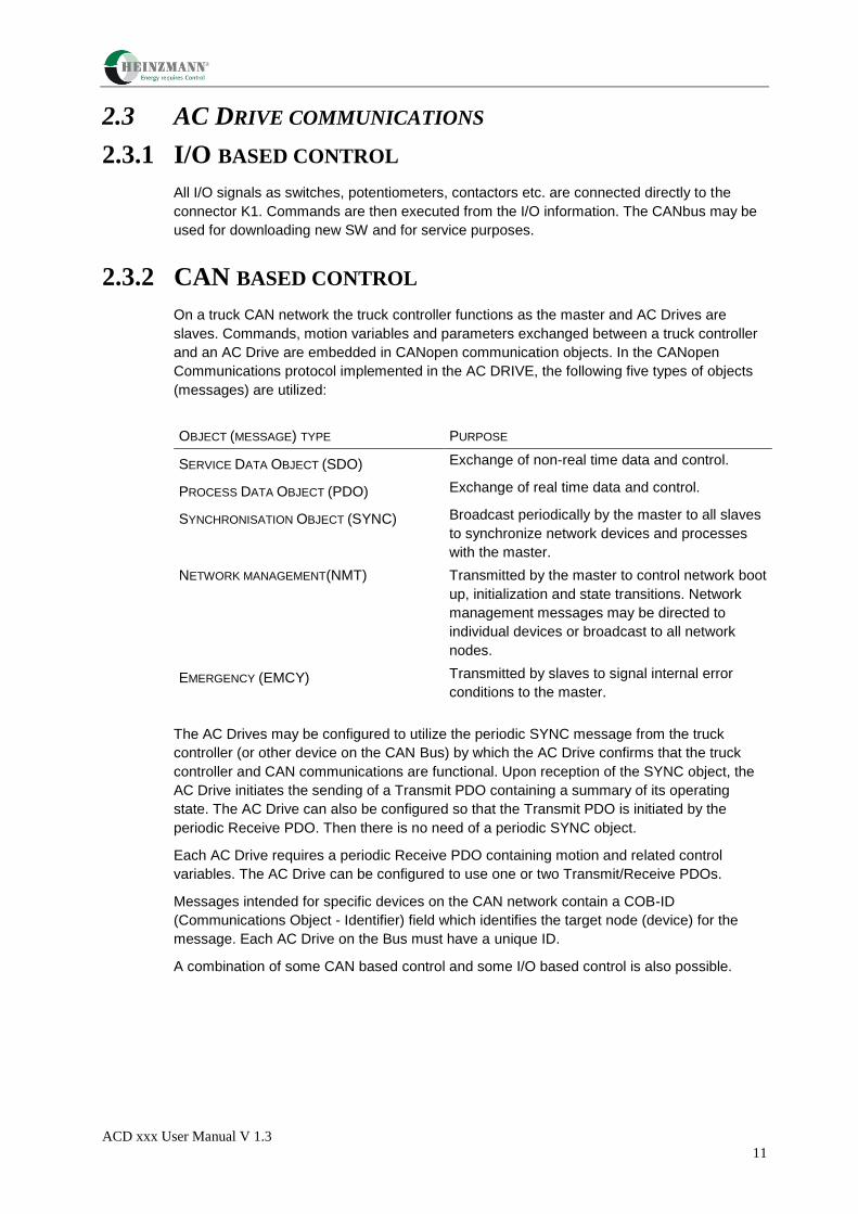
2.3.2 CAN BASED CONTROL
On a truck CAN network the truck controller functions as the master and AC Drives are
slaves. Commands, motion variables and parameters exchanged between a truck controller
and an AC Drive are embedded in CANopen communication objects. In the CANopen
Communications protocol implemented in the AC DRIVE, the following five types of objects
(messages) are utilized:
OBJECT (MESSAGE) TYPE PURPOSE
SERVICE DATA OBJECT (SDO) Exchange of non-real time data and control.
PROCESS DATA OBJECT (PDO) Exchange of real time data and control.
SYNCHRONISATION OBJECT (SYNC) Broadcast periodically by the master to all slaves
to synchronize network devices and processes
with the master.
NETWORK MANAGEMENT(NMT) Transmitted by the master to control network boot
up, initialization and state transitions. Network
management messages may be directed to
individual devices or broadcast to all network
nodes.
EMERGENCY (EMCY) Transmitted by slaves to signal internal error
conditions to the master.
The AC Drives may be configured to utilize the periodic SYNC message from the truck
controller (or other device on the CAN Bus) by which the AC Drive confirms that the truck
controller and CAN communications are functional. Upon reception of the SYNC object, the
AC Drive initiates the sending of a Transmit PDO containing a summary of its operating
state. The AC Drive can also be configured so that the Transmit PDO is initiated by the
periodic Receive PDO. Then there is no need of a periodic SYNC object.
Each AC Drive requires a periodic Receive PDO containing motion and related control
variables. The AC Drive can be configured to use one or two Transmit/Receive PDOs.
Messages intended for specific devices on the CAN network contain a COB-ID
(Communications Object - Identifier) field which identifies the target node (device) for the
message. Each AC Drive on the Bus must have a unique ID.
A combination of some CAN based control and some I/O based control is also possible.

ACD xxx User Manual V 1.3
12
3 INSTALLATION
3.1 INTRODUCTION
This chapter presents instructions and guidelines for installing an AC Drive in a vehicle. The
information is general in nature. The actual procedure for mounting the AC Drive in a specific
vehicle may vary from what is presented here or include additional steps.
We offer the following guidelines and precautions regarding mounting location for the AC
Drive:
AC Drive’s cover provides a measure of protection from liquids and particles
dripping, splashing or spraying onto the unit; however, the AC Drive is not
environmentally sealed. It should not be located in a place where it is subjected to
liquids under high pressure.
The protection class, IP54, is only valid when the mating connector, K1, is inserted.
The AC Drive LED status indicator provides useful diagnostic information for
troubleshooting of some vehicle problems. The troubleshooting process can be
facilitated if this indicator is visible.
High power levels are available at each of the connection posts. Therefore they
should be protected from accidental short circuits.
3.2 COOLING REQUIREMENTS
A massive heatsink comprising the entire bottom surface of the AC Drive transfers heat from
the Power Conversion section components into the body of the vehicle. Drives operating at
or near their continuous power output (1 hour rating) require different thermal
resistance depending on AC DRIVE size for dissipation of heat to maintain heat sink
temperature in the safe operating zone.
The AC Drive is cooled by the surface contact to the vehicle body. Observe demands to
surface roughness and surface flatness where the AC Drive is mounted to the vehicle body.
Apply thermal grease at the AC Drive before mounting for best cooling effect, see also
Surface demands.
For thermal resistance demands, see Operating environment.
3.3 CLEARANCES FOR ACCESS AND AIR CIRCULATION
For all AC Drive models 50 mm clearances in front of and behind the AC Drive are required
for airflow. 50 mm clearance above the AC Drive is required for installation/removal of
interface connectors and wiring. Refer to Dimensions for dimensions for the AC Drive.
For additional details on surface roughness and flatness demands for AC Drive see Table 9.
Apply thermal grease at the AC Drive before assembly.
ACD xxx User Manual V 1.3
13
3.4 ORIENTATION
The AC Drive is not to be orientated upside down; either horizontal or vertical mounting is
acceptable, although a horizontally mounted unit tolerates higher levels of mechanical shock
than a vertically mounted unit. Consideration should be given to visibility of the on-board
status indicator for maintenance purposes. High power levels are available at each of the
connection posts; therefore they should be protected from accidental short circuits.
i
For EMC and ESD purposes, we strongly recommend that both the AC Drice
and the Heatsink and the houses of the motors are connected to the chassis
l
3.5 TOOLS AND EQUIPMENT REQUIRED
The depth of thread in the vehicle body should be at least 8 mm. The following tools and
hardware are recommended for mounting an AC Drive:
Four (4) MC6S M6 x L 8.8 fzb DIN 912)/MRT M6 x L 8.8 fzb, T30 (DIN 7985) bolts or
equivalent (1/4 UNC) bolts, (pos 1).
Four (4) washer BRB 8.8 HB 200 fzb (DIN 125A), (12 x 6.4 x 1.6). Pos 2.
Heatsink thickness see Dimensions at page 41.
Thermal grease Electrolube HTC or Dow Corning 340
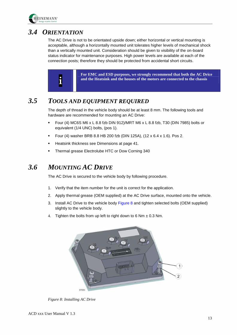
3.6 MOUNTING AC DRIVE
The AC Drive is secured to the vehicle body by following procedure.
1. Verify that the item number for the unit is correct for the application.
2. Apply thermal grease (OEM supplied) at the AC Drive surface, mounted onto the vehicle.
3. Install AC Drive to the vehicle body Figure 8 and tighten selected bolts (OEM supplied)
slightly to the vehicle body.
4. Tighten the bolts from up left to right down to 6 Nm ± 0.3 Nm.
Figure 8: Installing AC Drive

ACD xxx User Manual V 1.3
14
3.7 MOTOR AND BATTERY CONNECTIONS
on a topic.
i The motor connections (U, V, W) shall never be swapped
Table 2 provides a description of the five terminal post connections on the AC Drive.
Terminal Description
B+ Battery positive termination. (External battery fuse is required).
B- Battery negative termination
U, V, W Three-phase motor phase termination.
Table 2. Motor and battery connections.
CAUTION
Ring lugs for motor and battery connections must be adequately rated to
carry motor and battery currents; otherwise, overheating may result.
Crimp ring lugs onto ends of cables, then secure the lugs to terminal posts using bolts M6 x
L, lock washer and washer.
Figure 9 shows recommended connections to terminal posts. Use a torque wrench with 10
mm socket. Tighten bolts to 7,5 +- 0,5 Nm
Choose a suitable bolt length regarding to the thread depth.
Thread depth LT = 10 +2/ -1 mm.
The following equipment is required
5x Bolt M6S M6 x L 8.8 fzb (DIN931/933 or other M6 type of bolt) for battery and
motor connection (for L, see above).
5x Lock washer (DIN 127B). Dim. 12.2 x 6.5 x 1.6 mm or 1/4” ID.
5x Washer BRB 8.8 HB 200fzb (DIN 125A). Dim. 12 x 6.4 x 1.6mm or 1/4” ID.
5x Ring lugs with 6.5 mm hole diameter for battery and motor connection.
10 mm Box wrench.
It is recommended that a fuse is installed between the battery and + terminals on the AC
Drive. The fuse protects the drive and power distribution circuit in the event of a short circuit
fault in the power conversion section. Note that the fuse is not intended to protect the AC
Drive or motor against overloads. Since the AC Drive employs a software controlled closed

ACD xxx User Manual V 1.3
15
loop current regulator, motor overloads, drive overloads and shorts in the motor are normally
detected and managed by the AC Drive and typically do not cause the fuse to blow.
The fuse should be sized based on the AC Drive’s power output (2 min. rating). Compute DC
input current as follows:
VBATT
ratingkVAoutputpowerI INDC
1000).min2(][_
Select a fuse with rating and time delay characteristics which will carry IDC_IN indefinitely, but
blow within 2 - 3 seconds for 2 x IDC_IN.

ACD xxx User Manual V 1.3
16
3.8 CONTROL AND I/O CONNECTIONS
The connector (Plug AMPseal 23P 770680-1, Contact 770854-1) provides the electrical
interface for all control and I/O connections to the APS 2. Refer to Table 3 for a description
of the control and I/O signals.
Digital INPUT
Digital_IN_1 – DIGITAL_IN_6
Low < 2V; High>8V; Max B+, impedance 8,1 k
Analog INPUT 0 – 6,45V – impedance 43 kOhm
OPEN DRAIN OUTPUT Open Drain Output
sinks 1A cont.; 2A peak, with current measurement.
For inductive load, an external free wheel diode shall used.
The output is a PWM Controlled or ON/OFF
Pin-
No.
Type Name Description
1 Input KEY_IN KEY START supplies battery voltage to the AC Drive
for its internal processor and other functions. Applying
battery power initates the drive power up sequence.
This input should be fused (max 1 A) for protection.
Protected against reverse polarity
Power = 15 W
2 Output OPEN-DRAIN_1 PARKING BRAKE
(max 1 A)
3 Output SENSOR_SUPPLY Voltage supply for external sensors and Potentiometer
5 V DC; 50 mA max.
4 Output GND Ground reference for external sensors.
(Not B+ protected)
5 Input ENCODER_1 Motor feedback sensor CH_1 Input
6 Input ENCODER_2 Motor feedback sensor CH_2 Input
7 Input ANALOG_IN_2
8 CAN_GND Ground reference for CAN
9 Input ANALOG_IN_1 Potentiometer for Speed or Torque
10 Input ENCODER_4 Not Connected
11 Input ENCODER_3 Not Connected
12 Input DIGITAL_IN_5 SET CAN Node ID (LSB)
13 Input DIGITAL_IN_3 Switch FORWARD / REVERSE
14 Input n.c n.c

ACD xxx User Manual V 1.3
17
15 Output CAN_L CAN Bus low
16 Output MOTOR TEMP Temperature Sensor KTY 84-130 (not B+ protected)
17 Input DIGITAL_IN_4 Max. FORWARD SPEED 1 / 2
18 Output OPEN-DRAIN_2 WARNING / ERRORS
(max 1 A)
19 Input DIGITAL_IN_1 ENPO (Enable Power Output)
20 Input DIGITAL_IN_6 SET CAN Node ID (MSB) or
Forward Speed 3 / 4
21 Output OPEN-DRAIN_3 n.c
22 Output OPEN-DRAIN_4 n.c
23 Output CAN_H CAN Bus high
Table 3: Interface Connector K1 (AMP seal) Inputs and Outputs
Figure 10: Mating connector pin numbering (wiring side view)
1 2 3 4 5 6 7 8
10 9 11 12 13 14 15
16 17 18 19 20 21 22 23

ACD xxx User Manual V 1.3
18
3.8.1 Assigning Multiple CAN Node Addresses
This feature enables from 1 to 4 ACD controllers on a single CAN Bus to have different CAN
Bus Node addresses. Two digital inputs on each controller (PIN 12 & 20) are used to assign
each controller´s address as follows:
Valid in software-version: 69A21911C11-04.epf
CAN Node ID Hardware ID Connect Controller
DI5 (PIN 12) to:
Connect Controller
DI6 (PIN 20) to
5 0 N.C N.C
5 0 Battery – Battery –
6 1 KEY_IN (PIN1) Battery –
7 2 Battery – KEY_IN (PIN1)
8 3 KEY_IN (PIN1) KEY_IN (PIN1)
3.8.2 Parking Brake (OPEN_DRAIN_1)
i Note: This parking brake control function is not available when operating the controller remotely using PDO Communications. In case, the vehicle master controller controls the OPEN_DRAIN_1 directly

ACD xxx User Manual V 1.3
19
3.8.2 KEY START INPUT
The KEY START input (see Table 3 and Figure 3) supplies battery voltage to the AC Drive for
its internal processor and other functions. The vehicle start key generally controls power to
the KEY START input.
Fuse F2, should be sized according to the number of AC Drives and to protect the cable
area in the circuit (recommended fuse size max 10A) and the current consumption of the KEY
START input.
3.8.3 MOTOR SPEED SENSOR
The AC Drive can handle speed signals from analog or digital encoders. It provides speed
and direction feedback for the AC Drive. Only one type of encoder input is available and the
correct HW setup has to be chosen for each specific application.
An analog encoder (sin/cos) with two or three phases can be used. The two phase encoder
has 90 degrees phase shift between the channels and the three phase has 120 degrees
phase shift.
The sensor bearing is a typical example of a sensor integrated into the motor. It provides
speed and direction feedback for the AC Drive. The standard sensor bearing produces a
two-phase square wave output (Example SKF P/N 6206/VU1028 gives 64 pulses/ revolution
per phase).
Other pulse rates in the range 32 - 160 p/r can be selected in the Software. (Parameter is
accessible via CANopen).
K1 Connector
Pin-No.
Signal name Wire Color Motor Side
AMP Pin No.
3 Power supply for
Encoder (+5V DC)
green 7
4 Encoder GND yellow 6
5 Encoder CH 1 (cos) brown 1)
4
6 Encoder Ch 2 (sin) rose 1)
3
1) These two wires are motor depending. If the motor does not turn (i.e. oscillates around zero speed )
at the first start up, these two wires have to be swapped. If the rotation direction is not correct, the SW
parameter bit Inverted Rotation Direction in Application Setup Word (2020h:10) shall be set.
To minimize the possibility of electrical noise coupling into encoder lines, avoid routing encoder
cables next to conductors carring high currents or high current pulses. Noise immunity may also be
improved by using twisted conductor cable for encoder to drive connections.
supplemental information on a topic.
i Contact the motor manufacter to get the correct wiring; otherwise the
characteristics for the sensor will be changed or the sensor could be damaged.
There can be other connectors at motor side depending on OEM

ACD xxx User Manual V 1.3
20
3.8.4 TEMPERATURE SENSOR
i Contact the motor manufacter to get the correct wiring, otherwise the
characteristic for the sensor will be changed or the sensor can be damaged.
A temperature sensor with positive temperature coefficient (Philips P/N KTY 84-150)
embedded in the motor winding (by the motor manufacturer) provides a means for the AC
Drive to monitor motor temperature. Table 5 lists the colour coding and signal names for the
standard motor temperature sensor.
K1 Connector
Pin-No.
Signal name Sensor Wire Color
16 MOTOR Temperatur KTY + Red
4 GND KTY - Black
Table 5.: Standard Motor Temperature Sensor Wiring Color Codes
3.8.5 CAN BUS COMMUNICATIONS
The AC Drive employs an isolated CAN bus interface. As an example Figure 12 illustrates
the wiring configuration for AC Drive on a CAN network without one or more no isolated CAN
nodes The CAN Bus must be wired in a “Daisy chain” arrangement as shown in Figure 12.
Twisted pair wiring is required for the CAN_H and CAN_L signals. Both physical ends of the
CAN Bus must be terminated with 120 ohm resistances. A service device connector in a
safe, convenient location should be included in the wiring configuration. Additionally, CAN
Bus wiring should be physically separated from conductors carrying high currents.
The CAN bus is often opto-isolated to get sufficient noise margins in units that are switching
high currents (such as AC DRIVE). In these units, CAN GND is a reference point for the
CAN communication (CAN H and CAN L). CAN GND should be connected to B- at one
point, and preferably one point only. If all units on the CAN bus are isolated, CAN GND
should be externally connected to B- (see Figure 12).
ACD xxx User Manual V 1.3
21
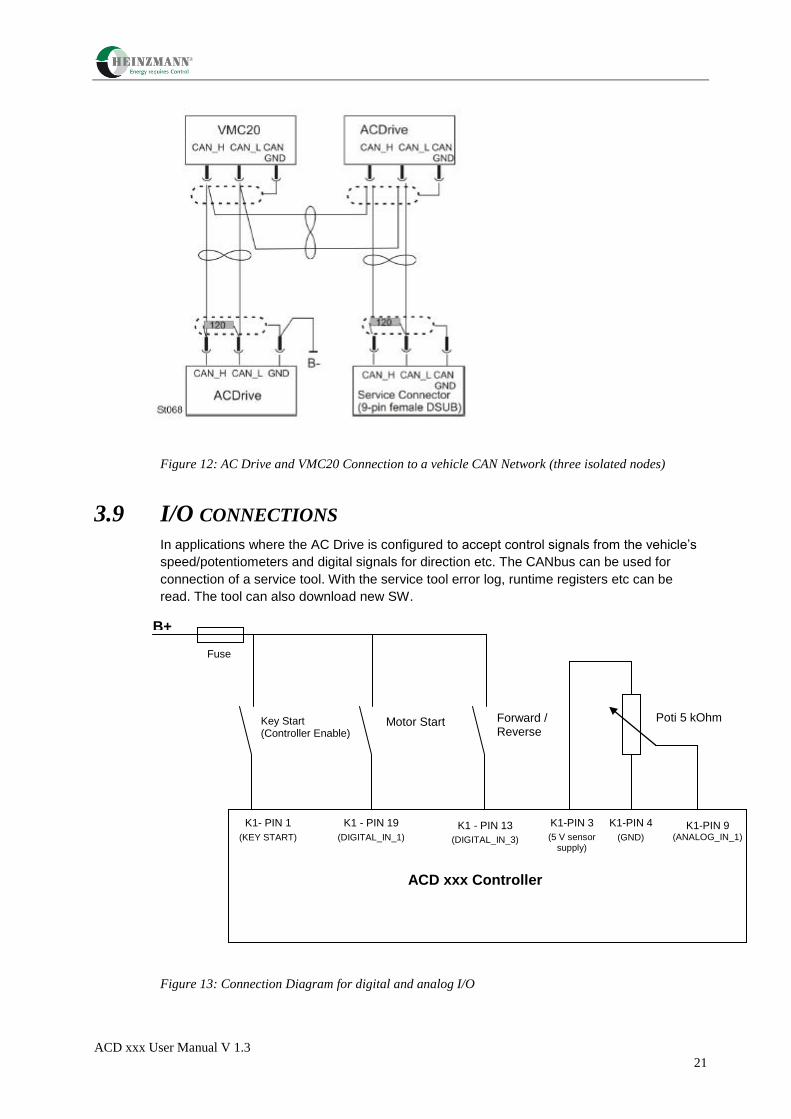
Figure 12: AC Drive and VMC20 Connection to a vehicle CAN Network (three isolated nodes)
3.9 I/O CONNECTIONS
In applications where the AC Drive is configured to accept control signals from the vehicle’s
speed/potentiometers and digital signals for direction etc. The CANbus can be used for
connection of a service tool. With the service tool error log, runtime registers etc can be
read. The tool can also download new SW.
Figure 13: Connection Diagram for digital and analog I/O
Key Start (Controller Enable)
Motor Start Forward / Reverse
ACD xxx Controller
K1- PIN 1
(KEY START)
K1 - PIN 19
(DIGITAL_IN_1)
K1 - PIN 13
(DIGITAL_IN_3)
Poti 5 kOhm
K1-PIN 3
(5 V sensor supply)
K1-PIN 4
(GND)
K1-PIN 9 (ANALOG_IN_1)
Fuse
B+

ACD xxx User Manual V 1.3
22
3.9.1 Connection Diagram
3.9.2 Motor Connector (Analogue Hallsensor and KTY 84 Series)
4 8
3 7
6
5
2
1
cosinus Output - brown
sinus Output - rose
KTY + -
KTY + red (from Motor)
KTY + white (to ACD)
KTY – (GND) - black (from Motor)
GND - yellow
Vcc (+5 V) - green
n.c.
B+
Speed Poti (5 or 10 kOhm)
1
2
3
4
5
6
7
8
9
10
11
12
13
14
15
16
17
18
19
20
21
22
23
Motorfeedback
(sin/cos) 6 – yellow (GND)
4 – brown (cos)
3 – rose (sin)
Switch KEY ON
Fw/Reverse
ENPO (Enable Power Output)
Motor TEMP KTY84 + 2 – white (KTY +)
3
2
7
CAN Low
GND
CAN High
SUB-D 9-pol
ACD 4805 Connector K1 23 p AMP seal
120 Ohm
Fuse 1 A
7 – green (Vcc)
Motorbrake
K1 (Relais)
Drive Mode
Charge Mode
Diode 1N4007
+
-
ACD xxx User Manual V 1.3
23
3.10 MAIN CONTACTOR
The main contactor functions as both a power distribution component and key component of
the AC Drive safety and protective interlocks circuit (see Figure 3). The main contactor is
energized when the AC Drives and the motors they control are ready and available to
execute motion.
When, as the result of some error/fault condition motion is not permitted, the main contactor
is deenergized. During vehicle power-up the main contactor allows direct application of
battery power to the AC Drive only after filter capacitors in the AC Drive have charged.
The following power output verses DC Input current relationship may be used when sizing a
main contactor and associated cabling:
][
][)(_
DCVVBATT
kVAoutputpowerCurrentInputDCI INDC
i It is essential to protect the AC Drive against reversed battery polarity
3.11 EMERGENCY STOP SWITCH
A manually operated Emergency Stop switch is usually included in the main contactor
energization circuit (see Figure 3). When activated, the Emergency Stop switch de energizes
the main contactor, removing battery power from the power conversion section of the AC
Drives.
i Note that removing power in this manner does not stop motor or produce any
braking action. With driving power removed. Motors and components they
drive simply coast to a stop. A mechanical brake must be used to stop the
vehicle motion in this situation.
ACD xxx User Manual V 1.3
24
4 START UP & COMMISSIONING
The AC Drive is a software configurable device. In a CAN (Controller Area Network) based
system, all aspects of AC Drive setup and operation are managed by a truck controller This
section presents a general procedure for the startup and verification of an AC Drive following
installation in an operational system (vehicle).
i The initial startup and verification of an AC Drive in a new application or new
design requires additional steps which are detailed in 4.1.
Built-in diagnostic functions monitor battery voltage, heatsink temperature and motor
temperature along with a number of additional error conditions. Warning and error conditions
are logged in Warning and Error status words, which are accessible to the truck controller.
The Troubleshooting guide provides procedures for pinpointing and eliminating the causes of
warning and error conditions.
4.1 CHECKS PRIOR TO INITIAL POWER UP
Perform the following before applying power to an AC Drive for the first time:
1. Verify that the proper AC DRIVE item number for the application has been installed.
Verify that the vehicle battery voltage matches the AC DRIVE´s Nominal DC Supply
Voltage rating listed on the product identification label affixed to the AC Drive (see
Figure 2).
2. Verify that all power and signal wiring to the AC DRIVE is correct.
3. Verify that connections to battery and motor terminals are tight.
4. Verify that the control I/O connector is fully mated and latched into position with the
mating connector (K1) on the AC DRIVE.
5. Verify that the AC DRIVE is correctly fused for the application. Refer to the vehicle
manufacturer’s maintenance documentation for the correct fuse size
6. On a traction application, block up or otherwise disable drives wheels to prevent the
possibility of unexpected vehicle motion or motion in the wrong direction during initial
checkout. On a lift application, open the valve to prevent the possibility of excess
pressure build-up (in the event of a pressure relief valve malfunction).
4.2 VERIFYING AC DRIVE READINESS FOR OPERATION
The following procedure is to verify that an AC Drive is functional and able to communicate
over the CAN Bus.
1. Apply battery power to the key start input. This applies logic power to the AC DRIVE.
2. Verify that the green LED indicator on each AC DRIVE is in the steady on condition. If
the indicator is flashing or off, it indicates an error/warning or other fault condition exists
within the AC DRIVE.
3. Consult the Troubleshooting guide of this manual for possible causes and corrective
actions.
ACD xxx User Manual V 1.3
25
4.3 CONFIGURING THE AC DRIVE FOR THE APPLICATION
As shipped from us in the beginning of a truck development project, the AC Drive is pre
configured with a set of default parameters appropriate for the drive model and motor
designated to be controlled by the AC Drive. These default parameters enable the Drive and
it’s motor to operate at fraction of their potential during initial start-up and checkout. A
necessary step in the AC Drive start-up procedure is to update those AC Drive parameters
adjustable by the user to the values established for the application. The user-adjustable
parameters are specified in the Object dictionary.
The general procedure for obtaining the correct configuration in the final product requires
normally that the established parameter values are used as default values in the from us
shipped AC Drives. The exceptions are the following:
The truck controller (or other device) downloads parameter values that are
depending on the truck configuration chosen in for example production and/or in the
field (for example performance modes). In order to retain a configuration, the
parameters have to be stored in the AC Drive’s non-volatile memory (EEPROM).
Thereafter the configuration is not changed until another configuration is
downloaded and stored in the same manner. Consult the vehicle manufacturer’s
maintenance information for specific instructions for performing this task.
When parameters are continuously updated via the real time data exchange from
the truck controller to the AC Drive.
The truck controller, by – for example – reading the checksum for all parameters stored in
the AC Drive’s EEPROM, can detect the situation where a drive’s configuration (set of
parameter values) is not correct for the application and normally prohibits vehicle operation
until the AC Drive has been correctly configured.
WARNING
All AC Drive parameter values established have to be verified and
validated prior to that the parameter values are used in the field by
the end user
This must be done in order to establish that all safety critical functions
in the vehicle, for example braking are working properly.
The complete range of parameters values that are updated by the
vehicle controller (or any other device) has also to be verified and
validated prior to that parameter values are used in the field by the
end user
During the process when the parameter values are established it is of
major importance to take proper safety precautions when testing since
wrong parameter values may jeopardize the operation of the vehicle
safety critical functions.
ACD xxx User Manual V 1.3
26
4.4 OPERATIONAL CHECKS IN VEHICLE
WARNING
For lift applications, make sure the pump rotates in the proper direction.
Rotating in the wrong direction may damage the pump.
Make sure that the motor and battery cables are connected correctly.
Incorrect motor or battery connections may destroy the AC Drive
1. With the main contactor open (not enabled), apply battery power to the AC Drive’s B+ (or
+) terminal through the inrush current limiting resistance.
2. Before enabling the main contactor, verify that the AC Drive’s filter capacitors have
charged. The filter capacitors are fully charged when the voltage measured between the
AC Drive’s + and B- terminals has reached battery voltage level.
3. Enable the main contactor.
4. Verify that the AC Drive and it’s associated motor start, stop and run properly at slow
speed and at full operational speed. Refer to Motor speed sensor.

ACD xxx User Manual V 1.3
27
5 MAINTENANCE
This section presents a list of periodic preventive maintenance items and procedures for
replacing an AC Drive.
The AC Drive contains no user adjustable or user replaceable
components beneath its protective cover. Do not remove the cover. Do not
clean the AC Drive using high-pressure water.
An Information
CAUTION
If drive was recently in operation, heatsink may be too hot to touch.
If necessary, allow the heatsink to cool before attempting to remove
drive.
Before removing or installing an AC Drive, disconnect battery
power from B+, + and KEY START inputs.
Wait 5 minutes for internal filter capacitors to self-discharge, or
apply a 100 ohm resistance between + and B- terminals for 15
seconds to discharge the filter capacitors.
To prevent personnel injury and protect the AC Drive from possible
damage due to voltage transients, the AC Drive’s internal filter
capacitors must be discharged as described in “Drive Removal”. Do
not short the + to B- terminal.
5.1 PERIODIC PREVENTIVE MAINTENANCE
The recommended periodic preventive maintenance procedures for the AC Drive are
minimal.
We recommend the following items be performed every six months (or more frequently if
necessary):
1. Remove all power from the drive. Apply a 100 ohm resistance between + and B-
terminals for 15 seconds to discharge the filter capacitors.
2. Remove accumulated dust and debris from the AC Drive. If air is used, use only air with
low pressure.
3. Retighten the bolts on the motor and battery terminal posts. (Torque requirement, See
Motor and battery connections)
4. Retighten the bolts on the AC Drive (Torque requirement, See Mounting AC Drive)

ACD xxx User Manual V 1.3
28
5. DRIVE REMOVAL
1. Remove all power from AC Drive’s B+, + and key start inputs.
2. Wait 5 minutes for internal filter capacitors to self-discharge, or apply a 100 ohm
resistance between + and B- terminals for 15 seconds to discharge the filter capacitors.
3. Remove bolts from battery and motor terminals and remove wires. Label the wires prior
to removal if not already labeled.
4. Depress locking latch on connector housing and remove mating connector from K1.
5. Remove bolts securing drive to the vehicle. Then remove drive from the vehicle.
5.3 DRIVE INSTALLATION
1. Verify that battery power to the B+, + and key start inputs has been removed.
2. • Clean the mounting surface before applying thermal grease on the unit before
mounting. See Tools and equipment required.
3. Mounting AC Drive
4. Install motor wires, battery wires and tighten the bolts. (Torque requirement, See Motor
and battery connections)
5. Insert mating connector into K1.
6. Perform initial start-up per the procedure titled Start up & commissioning.
ACD xxx User Manual V 1.3
29
6 TROUBLESHOOTING GUIDE
6.1 GENERAL
This troubleshooting guide presents procedures for diagnosing and eliminating the causes of
faults and error conditions affecting the AC Drive. The AC Drive is one component of a drive
chain, which may include mechanical drive components, a motor, hydraulics, electrical
controls, wiring and battery. AC Drive errors/faults may result from condition external to the
AC Drive. This troubleshooting guide addresses causes internal as well as external to the
AC Drive, which may produce fault or error conditions within the AC Drive.
documentation.
6.2 DOCUMENTATION FOR OEMS
The troubleshooting charts in this section are generic in nature and designed to stand alone
in order that OEMs may easily incorporate this information into the their documentation for
the vehicle. We can provide this troubleshooting information on electronic media in various
formats for OEMs who wish to import it into their documentation.
6.2.1 ERRORS
The AC Drive continuously monitors its internal operation as well as its interaction with the
motor and truck controller. Errors are serious problems, which prohibit continued operation of
the AC Drive.
When an error is detected
The AC Drive operating software immediately stops motion then shuts down the
drive’s power output to the motor.
The error bit in the Status Word is set.
The error bit GENERIC in the Error Register is set.
The appropriate error bit in the Extended Error register is set.
Sends out the high priority EMCY message with the Error Code.
The Error Code and the time are saved to the Error Log.
The Time is saved to the Operation Times.
The LED indicator starts to flash fast (10Hz).
6.2.2 WARNINGS
Less serious problems, which permit continued AC Drive operation, often at reduced
capacity, produce warnings. The AC Drive’s internal warning status is updated to reflect the
code(s) for existing warning conditions. Operating with active warning conditions does affect
the AC Drive status LED indicator, which changes from steady on to slow (1Hz) flashing.
When the root cause of a warning is removed, the AC Drive automatically removes any
reduced capacity restriction related to the warning condition.

ACD xxx User Manual V 1.3
30
When a warning is detected:
The warning bit in the Status Word is set.
The appropriate warning bit in the Extended Error register is set.
The LED indicator starts to flash slowly (1Hz).
6.2.3 STATUS INDICATOR
The status indicator, shown in Figure 14, provides a visual identification of the AC Drives
operating status.
STATUS DESCRIPTION
Steady green light The controller is OK
Fast flashing light. (10Hz) An error is reported to the controller.
When an error occurs, the AC Drive immediately stops
motion then shuts down the drive’s power output to the
motor.
Slow flashing light. (1Hz) A warning is active
ACD xxx User Manual V 1.3
31
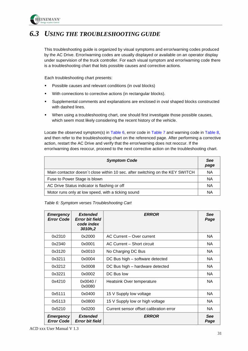
6.3 USING THE TROUBLESHOOTING GUIDE
This troubleshooting guide is organized by visual symptoms and error/warning codes produced
by the AC Drive. Error/warning codes are usually displayed or available on an operator display
under supervision of the truck controller. For each visual symptom and error/warning code there
is a troubleshooting chart that lists possible causes and corrective actions.
Each troubleshooting chart presents:
Possible causes and relevant conditions (in oval blocks)
With connections to corrective actions (in rectangular blocks).
Supplemental comments and explanations are enclosed in oval shaped blocks constructed
with dashed lines.
When using a troubleshooting chart, one should first investigate those possible causes,
which seem most likely considering the recent history of the vehicle.
Locate the observed symptom(s) in Table 6, error code in Table 7 and warning code in Table 8,
and then refer to the troubleshooting chart on the referenced page. After performing a corrective
action, restart the AC Drive and verify that the error/warning does not reoccur. If the
error/warning does reoccur, proceed to the next corrective action on the troubleshooting chart.
Symptom Code See page
Main contactor doesn´t close within 10 sec. after switching on the KEY SWITCH NA
Fuse to Power Stage is blown NA
AC Drive Status indicator is flashing or off NA
Motor runs only at low speed, with a ticking sound NA
Table 6: Symptom verses Troubleshooting Cart
Emergency Error Code
Extended Error bit field code index
3010h,2
ERROR See Page
0x2310 0x2000 AC Current – Over current NA
0x2340 0x0001 AC Current – Short circuit NA
0x3120 0x0010 No Charging DC Bus NA
0x3211 0x0004 DC Bus high – software detected NA
0x3212 0x0008 DC Bus high – hardware detected NA
0x3221 0x0002 DC Bus low NA
0x4210 0x0040 / 0x0080
Heatsink Over temperature NA
0x5111 0x0400 15 V Supply low voltage NA
0x5113 0x0800 15 V Supply low or high voltage NA
0x5210 0x0200 Current sensor offset calibration error NA
Emergency Error Code
Extended Error bit field
ERROR See Page

ACD xxx User Manual V 1.3
32
code index 3010h,2
0x5410 0x1000 Open Drain Output Current High NA
0x8100 0x0100 CAN Time Out NA
Table7: Error verses Troubleshooting Chart
Extendet Warning Bit field code Index
3010h, 1
Warning See page
0x0001 Low Voltage NA
0x0002 High Voltage NA
0x0004 DC Bus calibration NA
0x0008 Motor temperatur low, < - 50°C NA
0x0010 Motor temperatur high; > 145°C NA
0x0020 Motor temperature sensor not connected or short circuit NA
0x0040 Heatsink temperature 1 low < - 20°C NA
0x0080 Heatsink temperature 1 high > 85°C NA
0x0100 Heatsink temperature sensor 1 not connected or short circuit
NA
0x0200 Heatsink temperature 2 low < - 20°C NA
0x0400 Heatsink temperature 2 high > 85°C NA
0x0800 Heatsink temperature sensor 2 not connected or short circuit
NA
0x1000 Default parameters NA
0x2000 Power reduction due to temperature (motor or heatsink) NA
0x4000 Speed feedback sensor not connected or short circuit NA
0x8000 Current Measurement Calibration NA
0x40000 Open Drain Output High Warning NA
0x80000 Open Drain Output Current High Error NA
Table 8: Warning verses Troubleshooting Chart
ACD xxx User Manual V 1.3
33
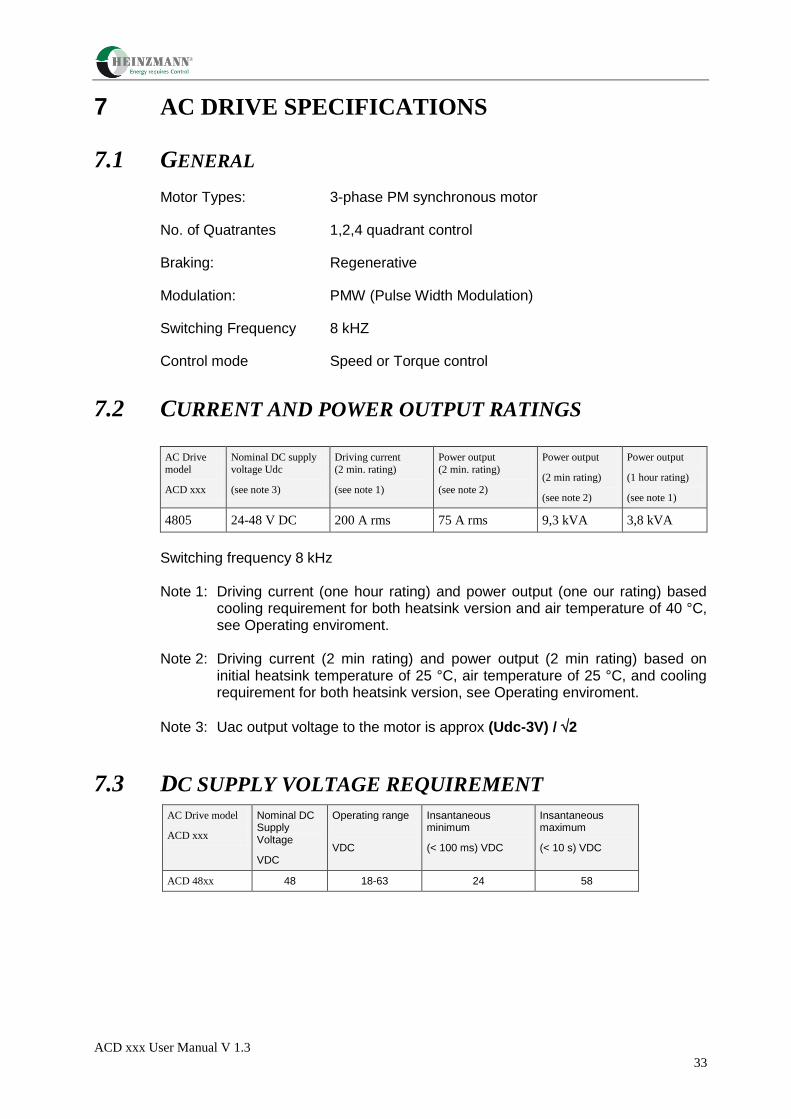
7 AC DRIVE SPECIFICATIONS
7.1 GENERAL
Motor Types: 3-phase PM synchronous motor
No. of Quatrantes 1,2,4 quadrant control
Braking: Regenerative
Modulation: PMW (Pulse Width Modulation)
Switching Frequency 8 kHZ
Control mode Speed or Torque control
7.2 CURRENT AND POWER OUTPUT RATINGS
AC Drive
model
ACD xxx
Nominal DC supply
voltage Udc
(see note 3)
Driving current
(2 min. rating)
(see note 1)
Power output
(2 min. rating)
(see note 2)
Power output
(2 min rating)
(see note 2)
Power output
(1 hour rating)
(see note 1)
4805 24-48 V DC 200 A rms 75 A rms 9,3 kVA 3,8 kVA
Switching frequency 8 kHz
Note 1: Driving current (one hour rating) and power output (one our rating) based cooling requirement for both heatsink version and air temperature of 40 °C, see Operating enviroment.
Note 2: Driving current (2 min rating) and power output (2 min rating) based on
initial heatsink temperature of 25 °C, air temperature of 25 °C, and cooling requirement for both heatsink version, see Operating enviroment.
Note 3: Uac output voltage to the motor is approx (Udc-3V) / 2
7.3 DC SUPPLY VOLTAGE REQUIREMENT
AC Drive model
ACD xxx
Nominal DC Supply Voltage
VDC
Operating range
VDC
Insantaneous minimum
(< 100 ms) VDC
Insantaneous maximum
(< 10 s) VDC
ACD 48xx 48 18-63 24 58
ACD xxx User Manual V 1.3
34
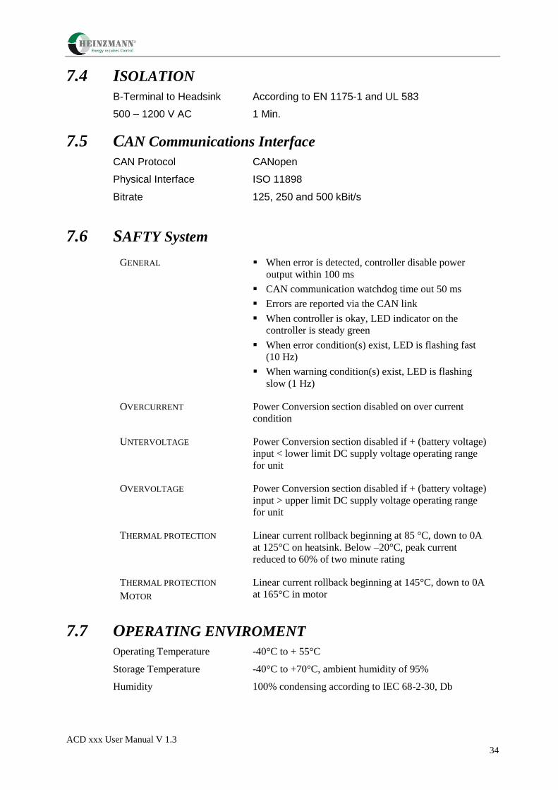
7.4 ISOLATION
B-Terminal to Headsink According to EN 1175-1 and UL 583
500 – 1200 V AC 1 Min.
7.5 CAN Communications Interface CAN Protocol CANopen
Physical Interface ISO 11898
Bitrate 125, 250 and 500 kBit/s
7.6 SAFTY System
GENERAL When error is detected, controller disable power
output within 100 ms
CAN communication watchdog time out 50 ms
Errors are reported via the CAN link
When controller is okay, LED indicator on the
controller is steady green
When error condition(s) exist, LED is flashing fast
(10 Hz)
When warning condition(s) exist, LED is flashing
slow (1 Hz)
OVERCURRENT Power Conversion section disabled on over current
condition
UNTERVOLTAGE Power Conversion section disabled if + (battery voltage)
input < lower limit DC supply voltage operating range
for unit
OVERVOLTAGE Power Conversion section disabled if + (battery voltage)
input > upper limit DC supply voltage operating range
for unit
THERMAL PROTECTION Linear current rollback beginning at 85 °C, down to 0A
at 125°C on heatsink. Below –20°C, peak current
reduced to 60% of two minute rating
THERMAL PROTECTION
MOTOR
Linear current rollback beginning at 145°C, down to 0A
at 165°C in motor
7.7 OPERATING ENVIROMENT Operating Temperature -40°C to + 55°C
Storage Temperature -40°C to +70°C, ambient humidity of 95%
Humidity 100% condensing according to IEC 68-2-30, Db

ACD xxx User Manual V 1.3
35
7.8 EMC Electromagnetic According to European standard EN 12895; Industrial
Compatibility Trucks (radiated immunity, emission, ESD)
Electrical FAST/ EN 61000-4-4 level 2
Transient / Burst
7.9 SAFETY AND TESTING STANDARDS COMPLIANCE Safety, Industrial Trucks EN 1175.-1
Basic Environment Testing IEC 68-2-30 Damp Heat Cycle
Procedure
Protection Class IP 54 Test IEC 60529 (with mating connector K1
installed)
7.10 MECHANICAL TESTS
VIBRATION IEC 68-2-64, Test FH, level 2
BUMP IEC 68-2-29, Test EB
SHOCK IEC 68-2-27, Test EA
7.11 WEIGHT
AC Drive model Weight kg
ACD 4805 1,6
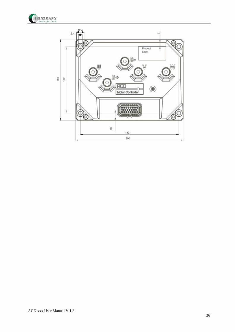
7.12 DIMENSIONS Figure 15 shows dimensions for AC Drive model 02 and 05 and drilling pattern for the flat heatsink versions and surface roughness and surface flatness demands for the flat heatsink versions. (Dimensions are in mm).
ACD xxx User Manual V 1.3
36