electric booster water heaters - parts...
TRANSCRIPT

Electric Booster Water HeatersImperial ‘S’, Compact ‘C’,Mini-Compact ‘MC’ Series
Installation and Operating ManualP/N 07.04.111.00
© 2012 Hatco Corporation
Register Online!(see page 2)
www.hatcocorp.com
Do not operate this equipment unless youhave read and understood the contents ofthis manual! Failure to follow theinstructions contained in this manual mayresult in serious injury or death. Thismanual contains important safetyinformation concerning the maintenance,use, and operation of this product. Ifyou’re unable to understand the contentsof this manual, please bring it to theattention of your supervisor. Keep thismanual in a safe location for futurereference.
No opere este equipo al menos que hayaleído y comprendido el contenido de estemanual! Cualquier falla en el seguimientode las instrucciones contenidas en estemanual puede resultar en un serio lesióno muerte. Este manual contieneimportante información sobre seguridadconcerniente al mantenimiento, uso yoperación de este producto. Si usted nopuede entender el contenido de estemanual por favor pregunte a susupervisor. Almacenar este manual enuna localización segura para la referenciafutura.
Ne pas utiliser cet équipement sans avoirlu et compris le contenu de ce manuel !Le non-respect des instructionscontenues dans ce manuel peut entraînerde graves blessures ou la mort. Cemanuel contient des informationsimportantes concernant l'entretien,l'utilisation et le fonctionnement de ceproduit. Si vous ne comprenez pas lecontenu de ce manuel, veuillez le signalerà votre supérieur. Conservez ce manueldans un endroit sûr pour pouvoir vous yréférer plus tard.
WARNING ADVERTENCIA AVERTISSEMENT

2
CONTENTS
Form No. EBOOSTERm-0712
INTRODUCTIONHatco Electric Booster Water Heaters are designed for use with commercial dish machines to boost the temperatureof the regularly available hot water, usually 110°–150°F (43°–66°C) up to 180°F (82°C). Water at 180°F (82°C) can beused as sanitizing rinse water in commercial dish machines inaccordance with Health Codes, NSF Standard #5 and plumbingcodes.
all Hatco Booster Heaters are ready for electrical and plumbingservice connections, with an adjustable ambient compensatedimmersion thermostat(s) and a high temperature limit switch.The service area is accessible from the front of the unit,permitting easy access.
Hatco Electric Booster Water Heaters are products of extensiveresearch and field testing. The materials used were selected formaximum durability, attractive appearance, and optimumperformance. Every unit is inspected and tested thoroughly priorto shipment.
This manual provides the installation, safety, and operatinginstructions for the Hatco Electric Booster Water Heaters. Hatcorecommends all installation, operating, and safety instructionsappearing in this manual be read prior to installation oroperation of the unit.
Safety information that appears in this manual is identified bythe following signal word panels:
WARNING indicates a hazardous situation which, if notavoided, could result in death or serious injury.
CAUTION indicates a hazardous situation which, if notavoided, could result in minor or moderate injury.
NOTICE is used to address practices not related topersonal injury.
NOTICE
CAUTION
WARNING
Important Owner Information ..............................................2Introduction...........................................................................2Important Safety Information...............................................3Model Description.................................................................5
all models ........................................................................5Imperial models “S” Series ..............................................5Compact models “C” Series.............................................5mini-Compact models “mC” Series..................................5
Specifications........................................................................6Circuit Breaker and Fused Disconnect Switch Sizes.......6Sizing Chart for Low-Temp Dish machines......................9Booster Heater Sizing Chart ..........................................10Capacity Charts .............................................................14Dimensions....................................................................15
Installation ...........................................................................17General ..........................................................................17Plumbing Installation......................................................18Electrical-all Sizes and Voltages ...................................23
Operation.............................................................................24General ..........................................................................24
Maintenance ........................................................................25General ..........................................................................25Thermostat adjustment..................................................25High Temperature Limit Safety Switch...........................25
Options and Accessories...................................................26Troubleshooting Guide ......................................................27Hatco Limited Warranty......................................................30Authorized Parts Distributors ............................Back Cover
IMPORTANT OWNER INFORMATIONRecord the model number, serial number, voltage, andpurchase date of the unit in the spaces below (specificationlabel located on the unit). Please have this information availablewhen calling Hatco for service assistance.
model No. ________________________________________
Serial No. ________________________________________
Voltage __________________________________________
Date of Purchase __________________________________
Register your unit!Completing online warranty registration will prevent delay inobtaining warranty coverage. access the Hatco website atwww.hatcocorp.com, select the Parts & Service pull-downmenu, and click on “Warranty Registration”.
Business 8:00 am to 5:00 PmHours: Central Standard Time (C.S.T.)
(Summer Hours: June to September – 8:00 am to 5:00 Pm C.S.T. monday through Thursday8:00 am to 2:30 Pm C.S.T. Friday)
Telephone: (800) 558-0607; (414) 671-6350
E-mail: [email protected]
Fax: (800) 690-2966 (Parts and Service)(414) 671-3976 (International)
additional information can be found by visiting our web site atwww.hatcocorp.com.
24 Hour 7 Day Parts and ServiceAssistance available in the United Statesand Canada by calling (800) 558-0607.

IMPORTANT SAFETy INFORMATION
Form No. EBOOSTERm-0712 3
ELECTRIC SHOCK HAzARD:• Unit must be installed by qualified, trained installers.
Installation must conform to all local electrical andplumbing codes. Installation by unqualified personnelwill void the unit warranty and may lead to electricshock or burn, as well as damage to unit and/or itssurroundings. Check with local plumbing and electricalinspectors for proper procedures and codes.
• Turn OFF power at fused disconnect switch/circuitbreaker and allow unit to cool before performing anycleaning, adjustments, or maintenance.
• Consult a licensed electrical contractor for properelectrical installation conforming to local electricalcodes and the National Electrical Code (N.E.C.).
• Unit is not weatherproof. Locate unit indoors whereambient air temperature is a minimum of 70°F (21°C).
• Do not place aftermarket covers on or over boosterheater. Doing so can cause temperature and moisturebuild-up resulting in premature failure and electricalshock.
• This unit must be serviced by qualified personnel only.Service by unqualified personnel may lead to electricshock or burn.
• Use only Genuine Hatco Replacement Parts whenservice is required. Failure to use Genuine HatcoReplacement Parts will void all warranties and maysubject operators of the equipment to hazardouselectrical voltage, resulting in electrical shock or burn.Genuine Hatco Replacement Parts are specified tooperate safely in the environments in which they areused. Some aftermarket or generic replacement partsdo not have the characteristics that will allow them tooperate safely in Hatco equipment.
valves supplied by Hatco are designed for high-temperature commercial operation. Do not substitute Hatcovalves with valves designed for domestic water heaters.
Temperature/pressure protective equipment should notbe less than a combination temperature/pressure reliefvalve certified by a nationally recognized testinglaboratory that maintains periodic inspection of theproduction of this equipment and meets the requirementsfor Relief valves and Automatic Shutoff Devices for HotWater Supply Systems, ANSI z21.22-1979. Thetemperature/pressure relief valve must be marked with aminimum set pressure not to exceed the markedhydrostatic test pressure of the booster heater as notedon the unit specifications.
ExPLOSION HAzARD: Do not store or use gasoline orother flammable vapors or liquids in the vicinity of this orany other appliance.
WARNINGFOR INSTALLING PRESSURE AND TEMPERATURERELIEF vALvES IN ACCORDANCE WITH AMERICANNATIONAL STD. z21.22-1979. Combination pressure andtemperature relief valves with extension thermostats mustbe installed so that the temperature-sensing element isimmersed in the water within the top 6" (152 mm) of thetank. They must be installed directly in a tank tapping.Combination pressure and temperature relief valves thatdo not have extension elements must be mounted directlyin a tank tapping located within the top 6" (152 mm) of thetank, and shall be adequately insulated and located so asto assure isolation from ambient conditions that are notindicative of stored water temperature. TO AvOID WATERDAMAGE OR SCALDING DUE TO vALvE OPERATION,DRAIN PIPE MUST BE CONNECTED TO vALvE OUTLETAND RUN TO A SAFE PLACE OF DISPOSAL. Dischargeline must be as short as possible and be the same size asthe valve discharge connection throughout its entirelength. Drain line must pitch downward from the valve andmust terminate between 1-1/2" (38 mm) and 6" (152 mm)above the floor drain where any discharge will be clearlyvisible. The drain line shall terminate plain, not threaded,with material serviceable for temperatures up to 250°F(121°C) or greater. Excessive length, over 30' (9.1 m), oruse of more than four elbows can cause a restriction andreduce the discharge capacity of the valve. No shut-offvalve shall be installed between the relief valve and tank,or in the drain line. valve lever must be trippedperiodically to assure that waterways are clear. Thisdevice is designated for emergency safety relief and shallnot be used as an operating control. The valves are set torelieve at 150 psi (1034 kPa) or when water temperaturereaches 210°F (99°C). Read tag on valve for additionalinformation.
Use only plumbing material suitable for a minimum watertemperature of 200°F (93°C). Materials used must meetNational Sanitation Foundation (NSF) specifications andall local plumbing codes and regulations.
Units are equipped with a high temperature limit safetyswitch that will shut off the power if the unit overheats.Contact an Authorized Hatco Service Agent if the hightemperature limit safety switch cannot be reset orcontinues to trip.
Install booster water heater in a horizontal position withthe base parallel to the floor and the inlet connection atthe lowest point. Improper installation could create anunsafe condition.
Do not connect booster water heaters to domestic(consumer) dish machines or other domestic utilizedequipment. This booster may damage domestic equipment.
WARNING
Read the following important safety information before using this equipment to avoid serious injury or death and to avoid damage to equipment or property.

IMPORTANT SAFETy INFORMATION
Form No. EBOOSTERm-07124
This product contains fiberglass, a product known to thestate of California to cause cancer, birth defects, or otherreproductive harm.
Install booster water heater as close as possible to acommercial dish machine. Employ re-circulation ifdistance between water heater and dish machine exceedsNational Sanitation Foundation (NSF) specifications offive (5) linear feet (1524 mm).
Follow standard welding safety and operational procedureswhen attaching sliderails to bottom of dishtable.
Make sure the dishtable is strong enough to support theweight of the heater AND water when installing with slidemounting brackets.
Refer to the BOOSTER HEATER SIzING CHART in thismanual to ensure proper sizing and avoid personal injuryand/or damage to the booster heater.
It is essential to recognize that even though a water heatermay be properly installed initially and approved, therealways exists the possibility that unknowing individualsmight alter or change the installation in a manner thatwould render it unsafe. Therefore, it is important that allsafety programs provide some mechanism to assure thatthese installations are inspected periodically.
This unit has no “user-serviceable” parts. If service isrequired on this unit, contact an Authorized Hatco ServiceAgent or contact the Hatco Service Department at 800-558-0607 or 414-671-6350; fax 800-690-2966; orInternational fax 414-671-3976.
BURN HAzARD:• Water in unit is very hot. Wear protective gloves and
proper attire when operating to avoid injury.• valves supplied by Hatco are designed for high
temperature commercial operation. Do not substituteHatco valves with valves designed for domestic waterheaters.
Do not use anti-siphon valves on incoming water line.
Check valves on incoming water line is not recommended.Damages caused by the use of check valves on unit willnot be covered by warranty.
Do not connect booster heater directly to a boiler orfurnace coil or any other uncontrolled temperaturesource. The booster heater thermostat could be damagedcausing unit to overheat.
Do not connect an expansion tank of any type to boosterheater water lines.
CAUTION
WARNINGHatco requires that two temperature/pressure gauges(Hatco P/N 03.01.003.00) be installed to ensure properoperation. Install one in the supply line before thepressure reducing valve and one in the outlet line as closeto the booster heater as possible. This provides a visualcheck of the water temperature and pressure before andafter the water heater.
If water supply pressure to the booster inlet is over 20 psi(138 kPa) during flow, install pressure reducing valve withbuilt-in bypass (Hatco P/N 03.02.004.00) for properoperation of dish machine rinse nozzles.
NOTE: The pressure reducing valve must be the typeequipped with a high pressure bypass, as supplied byHatco.
DO NOT turn on power to the booster heater until tank hasbeen filled with water and all air has been vented throughthe dish machine rinse nozzles. Heating elements willburn out in seconds if operated when not immersed inwater.
Always drain booster heater with power to the unit off orelement burnout could occur.
Use dielectric couplings when connecting dissimilarmetals, such as galvanized to copper. This will preventelectrolysis or premature plumbing damage.
Do not turn or adjust outlet water connection on all LargeCompact Series units (C-24 to C-57).
Do not turn or adjust inlet water connection on CompactSeries Booster Heaters or internal water flow will change.
Do not back out or loosen any pipe fittings or leaks mayoccur.
Do not lay unit on the side with the control panel. Damageto the unit could occur.
Incoming water in excess of 3 grains of hardness pergallon (GPG) (0.75 grains of hardness per liter [GPL]) mustbe treated and softened before being supplied to boosterheater(s). Water containing over 3 GPG (0.75 GPL) willdecrease efficiency, increase energy use, and reduce theoperating life of the unit through increased lime build-up.Product failure caused by liming or sediment buildup isnot covered under warranty.
Do not use deionized water. Deionized water will shortenthe life of water reservoir and heating element.
Units are voltage-specific. Refer to specification label forelectrical requirements before beginning installation.Connecting unit to incorrect power supply will voidproduct warranty and may damage unit.
CAUTION
NOTICE
Read the following important safety information before using this equipment to avoid serious injury or death and to avoid damage to equipment or property.

MODEL DESCRIPTION
Form No. EBOOSTERm-0712 5
All ModelsHatco Electric Water Booster Heaters are available in threemodels: Imperial, Compact, and mini-Compact. all standardmodels include a booster heater with low-water cut-off system,temperature/pressure relief valve, pressure reducing valve withbuilt-in high pressure bypass, two temperature/pressure gaugesand a high temperature limit safety switch.
Imperial Models “S” SeriesHatco Imperial models feature a Castone® tank with a 10 yearlimited warranty, a Power ON/OFF (I/O) switch, an indicator lightand 6" (152 mm) legs. Imperial units have a capacity of 16gallons (61 liters) and provide up to 573 gallons per hour (gph)(2169 liters per hour [lph]) of sanitizing rinse water based on a40°F (22°C) temperature rise.
Imperial model
Compact Models “C” SeriesHatco Compact models feature a Castone® tank with a 10 yearlimited warranty, a Power ON/OFF (I/O) switch, an indicator lightand either 6" (152 mm) legs or slide mounting brackets formounting under a dish table. Compact units have a capacity of6 gallons (23 liters) and provide up to 573 gph (2169 lph) ofsanitizing rinse water based on a 40°F (22°C) temperature rise.
Compact model
Mini-Compact Models “MC” SeriesHatco mini-Compact models feature a stainless steel tank and6" (152 mm) legs. mini-Compact units have a capacity of 3.2gallons (12 liters) and provide up to 172 gph (651 lph) ofsanitizing rinse water based on a 40°F (22°C) temperature rise.Ideal for either hot water sanitizing or point-of-use hot waterdispensing.
NOTE: Mini-Compact models can be configured with anoptional Power ON/OFF (I/O) switch.
mini-Compact model

kW voltage PhaseAmp Draw Breaker or Fuse
SizeCopper Wire
Size Conduit SizeL1 L2 L34 208 1 19 19 -- 30 10 1/2″ (13 mm)
240 1 17 17 -- 30 10 1/2″ (13 mm)480 1 8 8 -- 15 14 1/2″ (13 mm)
5 208 1 24 24 -- 30 10 1/2″ (13 mm)240 1 21 21 -- 30 10 1/2″ (13 mm)480 1 10 10 -- 15 14 1/2″ (13 mm)
6 208 1 29 29 -- 40 8 1/2″ (13 mm)208 3 14 25 14 40 8 1/2″ (13 mm)240 1 25 25 -- 40 8 1/2″ (13 mm)240 3 13 22 13 30 10 1/2″ (13 mm)380 3 9.2 9.2 9.2 15 14 1/2″ (13 mm)480 3 6 11 6 15 14 1/2″ (13 mm)600 3 5.7 5.7 5.7 15 14 1/2″ (13 mm)
7 208 1 34 34 -- 50 8 1/2″ (13 mm)208 3 17 29 17 40 8 3/4″ (19 mm)240 1 29 29 -- 40 8 1/2″ (13 mm)240 3 15 25 15 40 8 1/2″ (13 mm)380 3 11.4 11.4 11.4 15 14 1/2″ (13 mm)480 3 7 13 7 20 12 1/2″ (13 mm)600 3 6.7 6.7 6.7 15 14 1/2″ (13 mm)
9 208 1 43 43 -- 60 6 1/2″ (13 mm)208 3 22 38 22 50 8 1/2″ (13 mm)240 1 38 38 -- 50 8 1/2″ (13 mm)240 3 19 33 19 50 8 1/2″ (13 mm)380 3 13.3 13.3 13.3 20 12 1/2″ (13 mm)480 3 9 16.3 9 30 12 1/2″ (13 mm)600 3 8.7 8.7 8.7 15 14 1/2″ (13 mm)
9.9 208 1 47.5 47.5 -- 60 6 1/2″ (13 mm)208 3 27.5 27.5 27.5 40 8 1/2″ (13 mm)
10.4 208 3 28.8 28.8 28.8 40 8 1/2″ (13 mm)10.5 208 1 51 51 -- 70 4 3/4″ (19 mm)
208 3 29 29 29 40 8 1/2″ (13 mm)240 1 44 44 -- 60 6 1/2″ (13 mm)240 3 25.3 25.3 25.3 40 8 1/2″ (13 mm)480 3 12.6 12.6 12.6 20 12 1/2″ (13 mm)600 3 10 10 10 15 14 1/2″ (13 mm)
11.4 240 1 47.5 47.5 -- 60 6 1/2″ (13 mm)240 3 27.5 27.5 27.5 40 8 1/2″ (13 mm)480 3 13.7 13.7 13.7 20 12 1/2″ (13 mm)
12 208 1 58 58 -- 90 3 1″ (25 mm)208 3 33 33 33 50 8 1/2″ (13 mm)240 1 50 50 -- 70 4 3/4″ (19 mm)240 3 29 29 29 40 8 1/2″ (13 mm)380 3 19.1 19.1 19.1 30 10 1/2″ (13 mm)480 3 14.5 14.5 14.5 20 12 1/2″ (13 mm)600 3 11.6 11.6 11.6 15 14 1/2″ (13 mm)
SPECIFICATIONS
Form No. EBOOSTERm-07126
Circuit Breaker and Fused Disconnect Switch Sizes — 4 to 12 kW
The shaded area contains electrical information for International models only.
NOTE: 250 kcmil maximum wire size for terminal block.

kW volts Phase
Amp Draw Breaker or FuseSize
Copper WireSize Conduit SizeL1 L2 L3
13.5 208 1 65 65 -- 90 3 1″ (25 mm)208 1 38 38 38 50 8 1/2″ (13 mm)240 1 56.3 56.3 -- 90 3 1″ (25 mm)240 1 33 33 33 50 8 1/2″ (13 mm)480 1 16.3 16.3 16.3 30 10 1/2″ (13 mm)600 1 13 13 13 20 12 1/2″ (13 mm)
15 208 1 72 72 -- 90 3 1″ (25 mm)208 3 41.7 41.7 41.7 60 6 3/4″ (19 mm)240 1 62.5 62.5 -- 90 3 1″ (25 mm)240 3 36.1 36.1 36.1 50 8 1/2″ (13 mm)380 3 23.0 23.0 23.0 30 10 1/2″ (13 mm)480 3 18.1 18.1 18.1 30 10 1/2″ (13 mm)600 3 14.5 14.5 14.5 20 12 1/2″ (13 mm)
17.25 208 3 47.9 47.9 47.9 60 6 3/4″ (19 mm)18 208 1 86.5 86.5 -- 125 1 1-1/4″ (32 mm)
240 1 75 75 -- 100 3 1″ (25 mm)240 3 43.4 43.4 43.4 60 6 3/4″ (19 mm)380 3 27.3 27.3 27.3 40 8 1/2″ (13 mm)480 3 21.7 21.7 21.7 30 10 1/2″ (13 mm)600 3 17 17 17 30 10 1/2″ (13 mm)
24 208 1 115.4 115.4 -- 150 1/0 1-1/4″ (32 mm)208 3 66.7 66.7 66.7 90 3 1″ (25 mm)240 1 100 100 -- 125 1 1-1/4″ (32 mm)240 3 57.8 57.8 57.8 90 3 1-1/4″ (32 mm)380 3 38.0 38.0 38.0 50 8 1/2″ (13 mm)480 3 29.9 29.9 29.9 40 8 1/2″ (13 mm)600 3 23 23 23 30 10 1/2″ (13 mm)
27 208 1 129.8 129.8 -- 175 2/0 1-1/4″ (32 mm)208 3 75 75 75 100 3 1″ (25 mm)240 1 112.5 112.5 -- 150 1/0 1-1/4″ (32 mm)240 3 65 65 65 90 3 1″ (25 mm)380 3 38.1 38.1 38.1 50 8 1/2″ (13 mm)480 3 32.5 32.5 32.5 50 8 1/2″ (13 mm)600 3 26 26 26 40 8 1/2″ (13 mm)
30 208 1 144 144 -- 200 3/0 1-1/2″ (38 mm)208 3 83.3 83.3 83.3 125 1 1-1/4″ (32 mm)240 1 125 125 -- 175 2/0 1-1/2″ (38 mm)240 3 72.3 72.3 72.3 100 3 1″ (25 mm)380 3 45.7 45.7 45.7 60 6 3/4″ (19 mm)480 3 36 36 36 50 8 1/2″ (13 mm)600 3 28.9 28.9 28.9 40 8 1/2″ (13 mm)
SPECIFICATIONS
Form No. EBOOSTERm-0712 7
Wire size is based on THHN wire for branch circuit protection at .91 derate factor. Circuit breakers and fused disconnects are tobe mounted remote and wired by contractor. Sizes are based on the 2002 NEC table 310-16. Conduit size based on conductorsplus ground wire sizing per Table C1 from appendix C.
Only 6, 7 and 9 kW models can be field converted to single or three phase (open delta on 3 phase). Check wiring diagram suppliedwith the unit when converting the phase of the unit. Larger branch circuit required than for balanced 3 phase of equal kW. Balanced3 phase available, consult factory.
Circuit Breaker and Fused Disconnect Switch Sizes — 13.5 to 30 kW

kW volts Phase
Amp Draw Breaker or FuseSize
Copper WireSize Conduit SizeL1 L2 L3
36 208 1 173 173 -- 225 4/0 1-1/2″ (38 mm)208 3 100 100 100 125 1 1-1/4″ (32 mm)240 1 150 150 -- 200 3/0 1-1/2″ (38 mm)240 3 86.7 86.7 86.7 125 1 1-1/4″ (32 mm)380 3 54.7 54.7 54.7 70 4 1″ (25 mm)480 3 43.3 43.3 43.3 60 6 3/4″ (19 mm)600 3 34.7 34.7 34.7 50 8 1/2″ (13 mm)
39 208 1 187.5 187.5 -- 250 250 kcmil 2″ (51 mm)208 3 108 108 108 150 1/0 1-1/4″ (32 mm)240 1 163.5 163.5 -- 225 4/0 2″ (51 mm)240 3 94 94 94 125 1 1-1/4″ (32 mm)380 3 59.3 59.3 59.3 90 3 1″ (25 mm)480 3 47 47 47 60 6 3/4″ (19 mm)600 3 37.6 37.6 37.6 50 8 1/2″ (13 mm)
40 208 3 61.6 61.6 61.6 90 3 1″ (25 mm)40.5 208 3 112.5 112.5 112.5 150 1/0 1-1/4″ (32 mm)
240 3 97.5 97.5 97.5 125 1 1-1/4″ (32 mm)480 3 48.8 48.8 48.8 70 4 1″ (25 mm)600 3 39 39 39 50 8 3/4″ (19 mm)
45 208 3 125 125 125 175 2/0 1-1/2″ (38 mm)240 1 188 188 -- 250 250 kcmil 2″ (51 mm)240 3 108 108 108 150 1/0 1-1/4″ (32 mm)380 3 68.6 68.6 68.6 90 3 1″ (25 mm)480 3 54 54 54 70 4 1″ (25 mm)600 3 43.4 43.4 43.4 60 6 3/4″ (19 mm)
54 208 3 150 150 150 200 3/0 2″ (51 mm)240 3 130 130 130 175 2/0 1-1/2″ (38 mm)380 3 82 82 82 125 1 1-1/4″ (32 mm)480 3 65 65 65 90 3 1″ (25 mm)600 3 52 52 52 70 4 1″ (25 mm)
57 208 3 158.4 158.4 158.4 200 3/0 2″ (51 mm)240 3 137.3 137.3 137.3 175 2/0 1-1/2″ (38 mm)380 3 86.7 86.7 86.7 125 1 1-1/4″ (32 mm)480 3 68.6 68.6 68.6 90 3 1″ (25 mm)600 3 54.9 54.9 54.9 70 4 1″ (25 mm)
SPECIFICATIONS
Form No. EBOOSTERm-07128
Circuit Breaker and Fused Disconnect Switch Sizes — 36 to 57 kW
The shaded area contains electrical information for International models only.
Wire size is based on THHN wire for branch circuit protection at .91 derate factor. Circuit breakers and fused disconnects are tobe mounted remote and wired by contractor. Sizes are based on the 2002 NEC table 310-16. Conduit size based on conductorsplus ground wire sizing per Table C1 from appendix C.
NOTE: 250 kcmil maximum wire size for terminal block.
ELECTRIC SHOCK HAzARD: Consult a licensed electricalcontractor for proper electrical installation conforming tolocal electrical codes and the National Electrical Code(N.E.C.).
WARNING

SPECIFICATIONS
Form No. EBOOSTERm-0712 9
Sizing Chart for Low-Temp Dish MachinesBOOSTERS RATED AT 30°F (16°C) RISEDish Machine Model Number Electric
Compact ImperialBooster Booster
american Dish aH, aH-3D, aH-3D-S, aHC, aHC-3D, aHC-3D-S, ET-a, ET-aF, ET-aH, Service ET-a-m, ET-aH-m, ET-a-3, ET-aH-3, L-90-3D, L-90-3D-K, L-90-3D-K-S,
L-90-3D-S, L-90-3DC, L-90-3DC-K, L-90-3DC-K-S, L-90-3DC-S, L-90-3DW, L-90-3DW-K, L-90-3DW-K-S, L-90-3DW-S, L-90-3DWC, L-90-3DWC-K, L-90-3DWC-K-S, L-90-3DWC-S, WH, WHC . . . . . . . . . . . . . . . . . . . . . . . . . . . . . . .C-4 . . . . . . . .S-6
a-3D, a-3D-S, a, aC, aC-3D, aC-3D-S, aH-B, ET-aF-3, ET-aF-m, HT-25, L-60-3D, L-60-3D-K, L-60-3D-K-S, L-60-3D-S, L-60-3DC, L-60-3DC-K, L-60-3DC-K-S, L-60-3DC-S, L-60-3DW, L-60-3DW-K, L-60-3DW-K-S, L-60-3DW-S, L-60-3DWC, L-60-3DWC-K, L-60-3DWC-K-S, L-60-3DWC-S, L-72-3D, L-72-3D-K, L-72-3D-K-S, L-72-3D-S, L-72-3DC, L-72-3DC-K, L-72-3DC-K-S, L-72-3DC-S, L-72-3DW, L-72-3DW-K, L-72-3DW-K-S, L-72-3DWC-S, L-72-3DWC, L-72-3DWC-K, L-72-3DWC-K-S, L-72-3DWC-S, W, WC . . . . . . . . . . . . . . . . . . . . . . . . . . . . . . . . . . . . . . . . . . . . . . . . . . . . . . . . . . . .C-5 . . . . . . . .S-6
a-B, aD-25, SS-25, 5-aH, 5-aHS . . . . . . . . . . . . . . . . . . . . . . . . . . . . . . . . . . . . . . . . .C-6 . . . . . . . .S-6aF, aF-3D, aF-3D-S, aF-B, aFC, aFC-3D, aFC-3D-S, aFW, aFWC, 5, 5-S . . . . . . . .C-7 . . . . . . . .S-7aDC-44, aDC-66, 5-aG, 5-aGS, 5-CD-LF, 5-CD-RF . . . . . . . . . . . . . . . . . . . . . . . . . .C-9 . . . . . . . .S-9
Blakeslee U21-C . . . . . . . . . . . . . . . . . . . . . . . . . . . . . . . . . . . . . . . . . . . . . . . . . . . . . . . . . . . . . .C-4 . . . . . . . .S-6D-8-LT . . . . . . . . . . . . . . . . . . . . . . . . . . . . . . . . . . . . . . . . . . . . . . . . . . . . . . . . . . . . . .C-6 . . . . . . . .S-6DD-8-LT, R-CC64-LT, R-EE-LT . . . . . . . . . . . . . . . . . . . . . . . . . . . . . . . . . . . . . . . . . .C-12 . . . . . . .S-12Series XF-EE-LT, XF-PEE-LT, XF-LL-LT, XF-PLL-LT, XF-mm-LT, XF-Pmm-LT,
XF-EEE-LT, XF-LLL-LT, XF-mmm-LT . . . . . . . . . . . . . . . . . . . . . . . . . . . . . . . . . . . .C-13 . . . . . . .S-13Series R-L-LT, R-PL-LT, R-m-LT, R-Pm-LT, F-L-LT, F-PL-LT, F-m-LT,
F-Pm-LT (single tank) . . . . . . . . . . . . . . . . . . . . . . . . . . . . . . . . . . . . . . . . . . . . . . . .C-36 . . . . . . .S-36Series “R” & “F”-CC-LT, -EE-LT, -LL-LT, -mm-LT, -LLL-LT, -mmm-LT, -PCC-LT,
-PEE-LT, -PLL-LT, -Pmm-LT (multi-tank) . . . . . . . . . . . . . . . . . . . . . . . . . . . . . . . . . .C-24 . . . . . . .S-24Series XF-L-LT, XF-PL-LT, XF-m-LT, XF-Pm-LT (single tank) . . . . . . . . . . . . . . . . . . .C-54 . . . . . . .S-54Series XF-PEE-LT, XF-PLL-LT, XF-Pmm-LT, XF-EEE-LT, XF-LLL-LT,
XF-mmm-LT (multi-tank) . . . . . . . . . . . . . . . . . . . . . . . . . . . . . . . . . . . . . . . . . . . . . .C-36 . . . . . . .S-36Fa (Flight-a-Round) and Ra (Rack-a-Round) use comparable “F” listing.
Champion ULD, ULF . . . . . . . . . . . . . . . . . . . . . . . . . . . . . . . . . . . . . . . . . . . . . . . . . . . . . . . . . . .C-6 . . . . . . . .S-6DLF . . . . . . . . . . . . . . . . . . . . . . . . . . . . . . . . . . . . . . . . . . . . . . . . . . . . . . . . . . . . . . .C-13 . . . . . . .S-13KL44, KL66 . . . . . . . . . . . . . . . . . . . . . . . . . . . . . . . . . . . . . . . . . . . . . . . . . . . . . . . . .C-36 . . . . . . .S-36
Cma Dish machines a-1, aH-1, C-1, VaC-1, a-3, aH-3, C-3, L-1C, VaC-3, VaC-4, VaC-5, L-1X . . . . . . . .C-4 . . . . . . . .S-6
a-2, aH-1, aH-2, aH-3, B-3, C-1, C-2, C-3, EVa-1, EVa-2, EVa-3, EVa-4, EVa-5, VaC-2 . . . . . . . . . . . . . . . . . . . . . . . . . . . . . . . . . . . . . . . . . . . . . . . . . . . . . . .C-6 . . . . . . . .S-6
B-1 . . . . . . . . . . . . . . . . . . . . . . . . . . . . . . . . . . . . . . . . . . . . . . . . . . . . . . . . . . . . . . . .C-7 . . . . . . . .S-7B-2 . . . . . . . . . . . . . . . . . . . . . . . . . . . . . . . . . . . . . . . . . . . . . . . . . . . . . . . . . . . . . . . .C-9 . . . . . . . .S-9Cma-44L with tank heater, Cma-66L . . . . . . . . . . . . . . . . . . . . . . . . . . . . . . . . . . . . .C-24 . . . . . . .S-24CVa-1, CVa-2, CVa-3, CVa-4 . . . . . . . . . . . . . . . . . . . . . . . . . . . . . . . . . . . . . . . . . . .C-6 . . . . . . . .S-6CVa-5 . . . . . . . . . . . . . . . . . . . . . . . . . . . . . . . . . . . . . . . . . . . . . . . . . . . . . . . . . . . . . .C-7 . . . . . . . .S-7
Hobart LX-18C, LX-30C, LX-40C, Wm-5C, SR24C . . . . . . . . . . . . . . . . . . . . . . . . . . . . . . . . .C-4 . . . . . . . .S-6LT-1 . . . . . . . . . . . . . . . . . . . . . . . . . . . . . . . . . . . . . . . . . . . . . . . . . . . . . . . . . . . . . . . .C-6 . . . . . . . .S-6am-14, am-14C . . . . . . . . . . . . . . . . . . . . . . . . . . . . . . . . . . . . . . . . . . . . . . . . . . . . . .C-7 . . . . . . . .S-7C44a, CRS66a, CPW80a . . . . . . . . . . . . . . . . . . . . . . . . . . . . . . . . . . . . . . . . . . . . . .C-27 . . . . . . .S-27FT-800 . . . . . . . . . . . . . . . . . . . . . . . . . . . . . . . . . . . . . . . . . . . . . . . . . . . . . . . . . . . . .C-30 . . . . . . .S-30
Jackson Conserver 24LT, 200LT, ES1000, (Ecolab/Jackson) . . . . . . . . . . . . . . . . . . . . . . . . . .C-4 . . . . . . . .S-6Conserver 1, Conserver XL, ES2000 (Ecolab/Jackson) . . . . . . . . . . . . . . . . . . . . . . .C-9 . . . . . . . .S-9Conserver 2, Conserver XL2, ES4000 (Ecolab/Jackson) . . . . . . . . . . . . . . . . . . . . . .C-15 . . . . . . .S-15aJ-44, aJ-66, aJ-80 . . . . . . . . . . . . . . . . . . . . . . . . . . . . . . . . . . . . . . . . . . . . . . . . . . .C-18 . . . . . . .S-18
Knight EquipmentLTD. KLE-112-HL . . . . . . . . . . . . . . . . . . . . . . . . . . . . . . . . . . . . . . . . . . . . . . . . . . . . . . . . .C-5 . . . . . . . .S-6

SPECIFICATIONS
Form No. EBOOSTERm-071210
Booster Heater Sizing Chart ELECTRIC ELECTRIC
COMPACT BOOSTER IMPERIAL BOOSTERDish Machine Model Number Temperature Rise Temperature Rise
40°F (22°C) 70°F (39°C) 40°F (22°C) 70°F (39°C)
adamation CSL-1390, Ca-2, Ca-3, Ca-4, SLaP 44 . . . . . . . . . . . . . . . . . .C-39 . . . . . .(2)C-36 . . . . .S-39 . . . . .(2)S-36Ca, Ca-1 . . . . . . . . . . . . . . . . . . . . . . . . . . . . . . . . . . . . . . . . . .C-54 . . . . . .(2)C-45 . . . . .S-54 . . . . .(2)S-45
alvey FLC-10, SL-2S . . . . . . . . . . . . . . . . . . . . . . . . . . . . . . . . . . . . . . .--- . . . . . . . . .--- . . . . . . . .S-6 . . . . . . .S-9FLC-12, CL-1, CL-1 Turntable, Sa-5a . . . . . . . . . . . . . . . . . . . .--- . . . . . . . . .--- . . . . . . . .S-7 . . . . . . .S-12FL-2S . . . . . . . . . . . . . . . . . . . . . . . . . . . . . . . . . . . . . . . . . . . . . .--- . . . . . . . . .--- . . . . . . . .S-9 . . . . . . .S-13KS-70, KS70m SB . . . . . . . . . . . . . . . . . . . . . . . . . . . . . . . . . . . .--- . . . . . . . . .--- . . . . . . . .S-9 . . . . . . .S-15SL-2D . . . . . . . . . . . . . . . . . . . . . . . . . . . . . . . . . . . . . . . . . . . . .--- . . . . . . . . .--- . . . . . . .S-13 . . . . . .S-18FLC-36 . . . . . . . . . . . . . . . . . . . . . . . . . . . . . . . . . . . . . . . . . . . . .--- . . . . . . . . .--- . . . . . . .S-15 . . . . . .S-27KS-88 . . . . . . . . . . . . . . . . . . . . . . . . . . . . . . . . . . . . . . . . . . . . . .--- . . . . . . . . .--- . . . . . . .S-18 . . . . . .S-30KS-70-N, KS-88-N . . . . . . . . . . . . . . . . . . . . . . . . . . . . . . . . . . . .--- . . . . . . . . .--- . . . . . . .S-39 . . . . . . .---
american DishService HT-25 . . . . . . . . . . . . . . . . . . . . . . . . . . . . . . . . . . . . . . . . . . . . .C-7 . . . . . . . .C-12 . . . . . . .S-7 . . . . . . .S-12
aCD-44, aDC-66 . . . . . . . . . . . . . . . . . . . . . . . . . . . . . . . . . . . .C-12 . . . . . . .C-24 . . . . . .S-12 . . . . . .S-24
Blakeslee UC-21a, UC-21B . . . . . . . . . . . . . . . . . . . . . . . . . . . . . . . . . . . .C-4 . . . . . . . .C-4 . . . . . . .S-6 . . . . . . .S-6UC-21 . . . . . . . . . . . . . . . . . . . . . . . . . . . . . . . . . . . . . . . . . . . . .C-6 . . . . . . . .C-12 . . . . . . .S-6 . . . . . . .S-12D-8 . . . . . . . . . . . . . . . . . . . . . . . . . . . . . . . . . . . . . . . . . . . . . . .C-9 . . . . . . . .C-13 . . . . . . .S-9 . . . . . . .S-13D-9 . . . . . . . . . . . . . . . . . . . . . . . . . . . . . . . . . . . . . . . . . . . . . . .C-12 . . . . . . .C-17 . . . . . .S-12 . . . . . .S-17Series “R” & “F” -CC, -EE, -LL, -mm, -LLL, -mmm, -PCC,
-PEE, -PLL, -Pmm (multi-tank) with suffix “LC” . . . . . . . . . . .C-13 . . . . . . .C-24 . . . . . .S-13 . . . . . .S-24Series XF-EE, XF-LL . . . . . . . . . . . . . . . . . . . . . . . . . . . . . . . . .C-17 . . . . . . .C-30 . . . . . .S-17 . . . . . .S-30Series XF-LL, XF-PLL, XF-mm, XF-Pmm, XF-EEE, XF-LLL,
XF-mmm (multi-tank) with suffix “LC” . . . . . . . . . . . . . . . . . . .C-17 . . . . . . .C-30 . . . . . .S-17 . . . . . .S-30DD-8 . . . . . . . . . . . . . . . . . . . . . . . . . . . . . . . . . . . . . . . . . . . . .C-18 . . . . . . .C-30 . . . . . .S-18 . . . . . .S-30Series F-E, Fa-EE, Fa-PEE, Fa-LL, Fa-PLL, Fa-mm,
Fa-Pmm, F-EEE, Fa-EEE, Fa-LLL, Fa-mmm, F-PE . . . . . . .C-30 . . . . . . .C-54 . . . . . .S-30 . . . . . .S-54Series R-L, R-PL, R-m, R-Pm, F-L, F-PL, F-m,
F-Pm (single tank) . . . . . . . . . . . . . . . . . . . . . . . . . . . . . . . . . .C-36 . . . . . . .C-54 . . . . . .S-36 . . . . . .S-54Series XF-L, XF-PL, XF-m, XF-Pm, (single tank) . . . . . . . . . .(2)C-36 . . . . . . .--- . . . . . .(2)S-36 . . . . . .---Series R-E, R-PE, XF-PEE, XF-PLL, XF-Pmm, XF-EEE,
XF-LLL, XF-mmm (multi-tank) . . . . . . . . . . . . . . . . . . . . . . . .C-45 . . . . . .(2)C-30 . . . . .S-45 . . . . .(2)S-30Fa (Flight-a-Round) and Ra (Rack-a-Round) use comparable “F” listing.
Champion U-H1, UH-200, UH-200B, U-HB . . . . . . . . . . . . . . . . . . . . . . . . .C-4 . . . . . . . .C-6 . . . . . . .S-6 . . . . . . .S-6UL-150 . . . . . . . . . . . . . . . . . . . . . . . . . . . . . . . . . . . . . . . . . . . .C-4 . . . . . . . .C-7 . . . . . . .S-6 . . . . . . .S-7UH-150, UH-150B, UH-100, UH-100B, DHB-VS . . . . . . . . . . . .C-5 . . . . . . . .C-9 . . . . . . .S-6 . . . . . . .S-9D-H1, D-HB . . . . . . . . . . . . . . . . . . . . . . . . . . . . . . . . . . . . . . . .C-6 . . . . . . . .C-12 . . . . . . .S-6 . . . . . . .S-12D-H1T, D-HBT . . . . . . . . . . . . . . . . . . . . . . . . . . . . . . . . . . . . . .C-7 . . . . . . . .C-12 . . . . . . .S-7 . . . . . . .S-1244 DRWS, 66 DRPWWS, 80 DRHDPWWS, 70 DRFFPWWS .C-9 . . . . . . . .C-13 . . . . . . .S-9 . . . . . . .S-13PP-28 . . . . . . . . . . . . . . . . . . . . . . . . . . . . . . . . . . . . . . . . . . . . .C-9 . . . . . . . .C-15 . . . . . . .S-9 . . . . . . .S-15D-H1C, D-H1TC . . . . . . . . . . . . . . . . . . . . . . . . . . . . . . . . . . . . .C-9 . . . . . . . .C-18 . . . . . . .S-9 . . . . . . .S-1844 DR, 66 DRPW, 80 DRHDFW, 70 DRFFPW . . . . . . . . . . . . .C-12 . . . . . . .C-24 . . . . . .S-12 . . . . . .S-2466 WSPW, 44-WS, 66-WS, 64, 90FFPW, 100HDPW,
86 PW, 84, 106 PW,120 HDPW, 110 FFPW . . . . . . . . . . . . . .C-13 . . . . . . .C-24 . . . . . .S-13 . . . . . .S-24UC-CW6-WS . . . . . . . . . . . . . . . . . . . . . . . . . . . . . . . . . . . . . . .C-24 . . . . . . .C-36 . . . . . .S-24 . . . . . .S-36US-CW8-WS . . . . . . . . . . . . . . . . . . . . . . . . . . . . . . . . . . . . . . .C-24 . . . . . . .C-39 . . . . . .S-24 . . . . . .S-3944, 66 PW, 70FFPW, 80HDPW, 54, 76PW, 80FFPW,
90HDPW . . . . . . . . . . . . . . . . . . . . . . . . . . . . . . . . . . . . . . . . .C-24 . . . . . . .C-45 . . . . . .S-24 . . . . . .S-4540-KB, 40-KB-2-2, 40-KFWB, 40-KPRB, 40KPRB-2-2,
40KPRB-2-3, 60-KB, 60-KB-2-2, 60-KFWB, 60-KFWB-2-2, 60-KPRB, 60-KPRB-2-3, 64KB, 64-KB Corner, 64-KPRB, 64-KPRB Corner, 64 modular, 86 modular . . . . . . . . . . . . . . .C-30 . . . . . . .C-54 . . . . . .S-30 . . . . . .S-54
44-KB, 44-KB Corner, 44-KPRB, 44-KPRB Corner, 54-KB, 54-KB Corner, 54-KPRB, 54-KPRB Corner, 44 modular, 66 PW modular, UC** Series 6' Center, UC-C4 . . . . . . . . . . .C-36 . . . . . . .C-57 . . . . . .S-36 . . . . . .S-57
UC-CW4 . . . . . . . . . . . . . . . . . . . . . . . . . . . . . . . . . . . . . . . . . .C-36 . . . . . .(2)C-36 . . . . .S-36 . . . . .(2)S-36UC-C . . . . . . . . . . . . . . . . . . . . . . . . . . . . . . . . . . . . . . . . . . . . .C-45 . . . . . .(2)C-36 . . . . .S-45 . . . . .(2)S-36UC**CW Series 6' Center . . . . . . . . . . . . . . . . . . . . . . . . . . . . .C-45 . . . . . .(2)C-39 . . . . .S-45 . . . . .(2)S-40W-6-WS . . . . . . . . . . . . . . . . . . . . . . . . . . . . . . . . . . . . . . . . . . .C-45 . . . . . .(2)C-45 . . . . .S-45 . . . . .(2)S-40

SPECIFICATIONS
Form No. EBOOSTERm-0712 11
Booster Heater Sizing Chart (continued)ELECTRIC ELECTRIC
COMPACT BOOSTER IMPERIAL BOOSTERDish Machine Model Number Temperature Rise Temperature Rise
40°F (22°C) 70°F (39°C) 40°F (22°C) 70°F (39°C)
CmaDish machines Cma-180 . . . . . . . . . . . . . . . . . . . . . . . . . . . . . . . . . . . . . . . . . .C-7 . . . . . . . .C-12 . . . . . . .S-7 . . . . . . .S-12
Cma-44H with tank heater, Cma-66H . . . . . . . . . . . . . . . . . . .C-36 . . . . . . .C-45 . . . . . .S-36 . . . . . .S-45
Hobart am-15F . . . . . . . . . . . . . . . . . . . . . . . . . . . . . . . . . . . . . . . . . . . .C-4 . . . . . . . .C-6 . . . . . . .S-6 . . . . . . .S-6LXiC, LXiGC, LX-18C, LX-30C, LX-40C . . . . . . . . . . . . . . . . . .C-4 . . . . . . . .C-7 . . . . . . .S-6 . . . . . . .S-6LX-30, SR24, SR24H . . . . . . . . . . . . . . . . . . . . . . . . . . . . . . . . .C-4 . . . . . . . .C-7 . . . . . . .S-6 . . . . . . .S-7LX-18, am-14F, am-15, am-15T . . . . . . . . . . . . . . . . . . . . . . . .C-5 . . . . . . . .C-9 . . . . . . .S-6 . . . . . . .S-9Wm-5C . . . . . . . . . . . . . . . . . . . . . . . . . . . . . . . . . . . . . . . . . . . .C-6 . . . . . . . .C-9 . . . . . . .S-6 . . . . . . .S-9Wm-5 (without sump heater) . . . . . . . . . . . . . . . . . . . . . . . . . . .C-7 . . . . . . . .C-12 . . . . . . .S-7 . . . . . . .S-12am-14T, am-14TC . . . . . . . . . . . . . . . . . . . . . . . . . . . . . . . . . . .C-7 . . . . . . . .C-12 . . . . . . .S-7 . . . . . . .S-12am-14, am-14C . . . . . . . . . . . . . . . . . . . . . . . . . . . . . . . . . . . . .C-9 . . . . . . . .C-12 . . . . . . .S-9 . . . . . . .S-12am-12, am-12C* . . . . . . . . . . . . . . . . . . . . . . . . . . . . . . . . . . . .C-9 . . . . . . . .C-12 . . . . . . .S-9 . . . . . . .S-12
UW-50 . . . . . . . . . . . . . . . . . . . . . . . . . . . . . . . . . . . . . . . . . . . .--- . . . . . . . . .--- . . . . . . .S-15 . . . . . .S-24or Opti-Rinse C44a, CRS-66a, CCS-66a, CPW-80a, C54a,
CRS-76a, CCS-76a, CPW-90a, C64a, CRS-86a, CCS-86a, CPW-100a, C-88a, CRS-110a, CCS-110a, CPW-124a . . . .C-15 . . . . . . .C-27 . . . . . .S-15 . . . . . .S-27
C-54a, CRS-76a, CPW-90a, CCS-76a . . . . . . . . . . . . . . . . . .C-39 . . . . . .(2)C-36 . . . . .S-30 . . . . .(2)S-36C-44a, CRS-66a, CCS-66a, CPW-80a, C-64a, CRS-86a,
CCS-86a, CPW-100a . . . . . . . . . . . . . . . . . . . . . . . . . . . . . . .C-30 . . . . . . .C-54 . . . . . .S-30 . . . . . .S-54C-88a, CRS-110a, CPW-124a, CCS-110a . . . . . . . . . . . . . . .C-36 . . . . . . .C-54 . . . . . .S-36 . . . . . .S-54or Opti-Rinse C44aW, CRS-66aW, CCS-66aW, CPW-80aW . .C-9 . . . . . . . .C-15 . . . . . . .S-9 . . . . . . .S-15C-44aW, CRS-66aW, CPW-80aW, CCS-66aW . . . . . . . . . . . .C-12 . . . . . . .C-24 . . . . . .S-12 . . . . . .S-24C-44, CRS-66, CPW-80 . . . . . . . . . . . . . . . . . . . . . . . . . . . . . .C-36 . . . . . . .C-54 . . . . . .S-36 . . . . . .S-54C-54, CRS-76, CPW-90 . . . . . . . . . . . . . . . . . . . . . . . . . . . . . .C-54 . . . . . .(2)C-39 . . . . .S-54 . . . . .(2)S-39C-64W, CRS-86W, CPW-100W, C-88W, CRS-110W,
CPW-124W, CCS-86W . . . . . . . . . . . . . . . . . . . . . . . . . . . . . .C-24 . . . . . . .C-36 . . . . . .S-24 . . . . . .S-36C-64, CRS-86, CPW-100 . . . . . . . . . . . . . . . . . . . . . . . . . . . . .C-45 . . . . . .(2)C-36 . . . . .S-45 . . . . .(2)S-36FT800W, FT-900W . . . . . . . . . . . . . . . . . . . . . . . . . . . . . . . . . .C-24 . . . . . . .C-39 . . . . . .S-24 . . . . . .S-39FT-600, FT-700 . . . . . . . . . . . . . . . . . . . . . . . . . . . . . . . . . . . . .C-54 . . . . . .(2)C-39 . . . . .S-54 . . . . .(2)S-39FT800 . . . . . . . . . . . . . . . . . . . . . . . . . . . . . . . . . . . . . . . . . . . .C-39 . . . . . .(2)C-39 . . . . .S-39 . . . . .(2)S-39Opti-Rinse* . . . . . . . . . . . . . . . . . . . . . . . . . . . . . . . . . . . . . . . .C-36 . . . . . . .C-57 . . . . . .S-36 . . . . . .S-57FT800S, FT-900S . . . . . . . . . . . . . . . . . . . . . . . . . . . . . . . . . . .C-39 . . . . . .(2)C-36 . . . . .S-39 . . . . .(2)S-36UTW-28, UTW-28C . . . . . . . . . . . . . . . . . . . . . . . . . . . . . . . . . . .--- . . . . . . . . .--- . . . . . . .S-18 . . . . . .S-36FRC and FR (Fast Rack Series) use comparable “C” line listing.
Insinger GS 302, GS-14 . . . . . . . . . . . . . . . . . . . . . . . . . . . . . . . . . . . . . .C-4 . . . . . . . .C-4 . . . . . . .S-6 . . . . . . .S-645Sa-5 . . . . . . . . . . . . . . . . . . . . . . . . . . . . . . . . . . . . . . . . . . . .C-4 . . . . . . . .C-7 . . . . . . .S-6 . . . . . . .S-7Commander 18-5C, 18-5CH, CS-5, CS-5C, CS-5CH, CS-5H . .C-6 . . . . . . . .C-12 . . . . . . .S-6 . . . . . . .S-12Commander 18-5, 18-5H, Ensign 40-2 . . . . . . . . . . . . . . . . . . .C-6 . . . . . . . .C-12 . . . . . . .S-6 . . . . . . .S-12admiral 44-4, 66-4 . . . . . . . . . . . . . . . . . . . . . . . . . . . . . . . . . . .C-24 . . . . . . .C-36 . . . . . .S-24 . . . . . .S-39135-20, 185-20, 250-20, 60-20, 85-20, R-106-2 . . . . . . . . . . . .C-24 . . . . . . .C-25 . . . . . .S-24 . . . . . .S-45Speeder 64, 86-3, Century (all), Super 106-2 . . . . . . . . . . . . . .C-24 . . . . . . .C-45 . . . . . .S-24 . . . . . .S-45Trac 878 . . . . . . . . . . . . . . . . . . . . . . . . . . . . . . . . . . . . . . . . . .C-24 . . . . . . .C-36 . . . . . .S-24 . . . . . .S-36Century 14, Clipper RC-##-RPW-W . . . . . . . . . . . . . . . . . . . . .C-24 . . . . . . .C-39 . . . . . .S-24 . . . . . .S-39Clipper (all), R106-2, Super 106-2, Trac 321, Trac 321-2/RPW C-27 . . . . . . .C-45 . . . . . .S-27 . . . . . .S-45Defender-(1) . . . . . . . . . . . . . . . . . . . . . . . . . . . . . . . . . . . . . . .C-30 . . . . . . .C-54 . . . . . .S-30 . . . . . .S-54Defender . . . . . . . . . . . . . . . . . . . . . . . . . . . . . . . . . . . . . . . . . .C-36 . . . . . . .C-54 . . . . . .S-36 . . . . . .S-54master (all) . . . . . . . . . . . . . . . . . . . . . . . . . . . . . . . . . . . . . . . .C-36 . . . . . . .C-57 . . . . . .S-36 . . . . . .S-57Ca-3 . . . . . . . . . . . . . . . . . . . . . . . . . . . . . . . . . . . . . . . . . . . . . .--- . . . . . . . . .--- . . . . . . . .S-9 . . . . . . .S-24Da-3 . . . . . . . . . . . . . . . . . . . . . . . . . . . . . . . . . . . . . . . . . . . . . .--- . . . . . . . . .--- . . . . . . .(2)S-9 . . . . .(2)S-24For outdated models, consult factory for correct booster.
* Hobart model am-12 with serial no. 12-067-357 or below and model am-12C with serial no. 12-067-537 or below require slightlylarger booster than listed. ‘C’ models with serial no. 85-1041605 or greater use Opti-Rinse.
Shaded area indicates older models prior to Opti-Rinse.

SPECIFICATIONS
Form No. EBOOSTERm-071212
Booster Heater Sizing Chart (continued)ELECTRIC ELECTRIC
COMPACT BOOSTER IMPERIAL BOOSTERDish machine Model Number Temperature Rise Temperature Rise
40°F (22°C) 70°F (39°C) 40°F (22°C) 70°F (39°C)
Jackson JP-24, JP-24B, JP-24F, JP-24BF . . . . . . . . . . . . . . . . . . . . . . . .C-4 . . . . . . . .C-6 . . . . . . .S-6 . . . . . . .S-624B Series . . . . . . . . . . . . . . . . . . . . . . . . . . . . . . . . . . . . . . . . . .--- . . . . . . . . .C-4 . . . . . . . .--- . . . . . . . .S-610aB, 10aPRB . . . . . . . . . . . . . . . . . . . . . . . . . . . . . . . . . . . . . .--- . . . . . . . . .C-5 . . . . . . . .--- . . . . . . . .S-644CE*, 66 CERPW . . . . . . . . . . . . . . . . . . . . . . . . . . . . . . . . . .C-30 . . . . . . .C-54 . . . . . .S-30 . . . . . .S-5454CE, 76 CERPW . . . . . . . . . . . . . . . . . . . . . . . . . . . . . . . . . . .C-36 . . . . . .(2)C-30 . . . . .S-36 . . . . .(2)S-3064CE, 86 CERPW . . . . . . . . . . . . . . . . . . . . . . . . . . . . . . . . . . .C-27 . . . . . . .C-39 . . . . . .S-27 . . . . . .S-39100 . . . . . . . . . . . . . . . . . . . . . . . . . . . . . . . . . . . . . . . . . . . . . . .C-12 . . . . . . .C-24 . . . . . .S-12 . . . . . .S-24100B, 100PRB, 150B, 150PRB . . . . . . . . . . . . . . . . . . . . . . . . . .--- . . . . . . . . .C-9 . . . . . . . .--- . . . . . . . .S-9150 . . . . . . . . . . . . . . . . . . . . . . . . . . . . . . . . . . . . . . . . . . . . . . .C-12 . . . . . . .C-18 . . . . . .S-12 . . . . . .S-18200 . . . . . . . . . . . . . . . . . . . . . . . . . . . . . . . . . . . . . . . . . . . . . . .C-7 . . . . . . . .C-12 . . . . . . .S-7 . . . . . . .S-12200B . . . . . . . . . . . . . . . . . . . . . . . . . . . . . . . . . . . . . . . . . . . . . .--- . . . . . . . . .C-6 . . . . . . . .--- . . . . . . . .S-6Tempstar, Tempstar SDS, Tempstar HH . . . . . . . . . . . . . . . . . . .C-6 . . . . . . . .C-12 . . . . . . .S-6 . . . . . . .S-12TS-44, TS-66 . . . . . . . . . . . . . . . . . . . . . . . . . . . . . . . . . . . . . . .C-24 . . . . . . .C-36 . . . . . .S-24 . . . . . .S-36aJ-44, aJ-66, aJ-80, WH-44, ES-4400, ES-6600 (Ecolab/Jackson) . . . . . . . . . . . . . . . . . . . . . . . . . . . .C-24 . . . . . . .C-45 . . . . . .S-24 . . . . . .S-45aJ-54, aJ-76, aJ-90 . . . . . . . . . . . . . . . . . . . . . . . . . . . . . . . . . .C-36 . . . . . .(2)C-36 . . . . .S-36 . . . . .(2)S-36aJ-64, aJ-86, aJ-100 . . . . . . . . . . . . . . . . . . . . . . . . . . . . . . . . .C-24 . . . . . . .C-39 . . . . . .S-24 . . . . . .S-39*model #44CE w/SN1999 or below requires larger booster than listed.
KnightEquipment LTD. KLE-112-HL . . . . . . . . . . . . . . . . . . . . . . . . . . . . . . . . . . . . . . . .C-7 . . . . . . . .C-12 . . . . . . .S-7 . . . . . . .S-12
meiko K-44, K-66, K-80 . . . . . . . . . . . . . . . . . . . . . . . . . . . . . . . . . . . .C-24 . . . . . . .C-36 . . . . . .S-24 . . . . . .S-36K-54, K-76, K-90, K-64, K-86, K-100 . . . . . . . . . . . . . . . . . . . .C-24 . . . . . . .C-45 . . . . . .S-24 . . . . . .S-45
metalwash/Intedge FW4 . . . . . . . . . . . . . . . . . . . . . . . . . . . . . . . . . . . . . . . . . . . . . .C-12 . . . . . . .C-18 . . . . . .S-12 . . . . . .S-18RS-30a, RS-28L . . . . . . . . . . . . . . . . . . . . . . . . . . . . . . . . . . . . .--- . . . . . . . . .--- . . . . . . .S-15 . . . . . .S-24RT-74, RT-60, RT-42B, RT-42BC . . . . . . . . . . . . . . . . . . . . . . . .--- . . . . . . . . .--- . . . . . . .S-27 . . . . . .S-40RS-2R . . . . . . . . . . . . . . . . . . . . . . . . . . . . . . . . . . . . . . . . . . . . .--- . . . . . . . . .--- . . . . . . .S-30 . . . . . .S-45

SPECIFICATIONS
Form No. EBOOSTERm-0712 13
Booster Heater Sizing Chart (continued)ELECTRIC ELECTRIC
COMPACT BOOSTER IMPERIAL BOOSTERDish machine Model Number Temperature Rise Temperature Rise
40°F (22°C) 70°F (39°C) 40°F (22°C) 70°F (39°C)
Stero SCT-44-10-LW, SCT-44-LW, SCT-66S-LW, SCT-76S-LW, SCT-76SC-LW, SCT-90S-LW . . . . . . . . . . . . . . . . . . . . . . . . .C-12 . . . . . . .C-24 . . . . . .S-12 . . . . . .S-24
SC-1-2-4-LW, SC-1-6-4-LW, SC-2-4-LW, SC-5-2-4-LW, SC-5-6-4-LW, SC-6-4-LW . . . . . . . . . . . . . . . . . . . . . . . . . . . .C-24 . . . . . . .C-45 . . . . . .S-24 . . . . . .S-45
SCT-64, SCT-86S, SCT-94S, SCT-94SC . . . . . . . . . . . . . . . . .C-24 . . . . . . .C-39 . . . . . .S-24 . . . . . .S-39SCT-108S, SCT-108SC, SCT-76, SCT-94Sm . . . . . . . . . . . . . .C-27 . . . . . . .C-54 . . . . . .S-27 . . . . . .S-54SC-6-4, SCT-44, SCT-44-10, SCT-66S, SCT-76S,
SCT-76SC, SCT-90S . . . . . . . . . . . . . . . . . . . . . . . . . . . . . . .C-30 . . . . . . .C-54 . . . . . .S-30 . . . . . .S-54SCT-120S, SCT-120SC, SCT-120Sm, SCT-150Sm . . . . . . . . .C-36 . . . . . . .C-57 . . . . . .S-36 . . . . . .S-57STW-110, SC-1-2-7-4, SC-1-6-3-4, SC-1-6-7-4, SC-2-7-4,
SC-5-2-7-4, SC-5-6-3-4, SC-5-6-7-4, SC-6-3-4, SC-6-7-4 . . .C-39 . . . . . .(2)C-36 . . . . .S-39 . . . . .(2)S-39SC-1-2-4, SC-1-6-4, SC-2-4, SC-5-2-4, SC-5-6-4 . . . . . . . . . .C-45 . . . . . .(2)C-36 . . . . .S-45 . . . . .(2)S-45SCT-44-10-SC-1-3-4, SCT-44-10-3-4, SCT-44-SC-1-3-4,
SCT-44-SC-3-4, SCT-54-SC-1-3-4, SCT-54-SC-3-4, SCT-76S-SC-3-4 . . . . . . . . . . . . . . . . . . . . . . . . . . . . . . . . . . .C-45 . . . . . .(2)C-36 . . . . .S-40 . . . . .(2)S-36
STPC (Four tank) . . . . . . . . . . . . . . . . . . . . . . . . . . . . . . . . . . .C-24 . . . . . . .C-39 . . . . . .S-24 . . . . . .S-39STPCW (Four tank) . . . . . . . . . . . . . . . . . . . . . . . . . . . . . . . . . .C-24 . . . . . . .C-45 . . . . . .S-24 . . . . . .S-40STPC . . . . . . . . . . . . . . . . . . . . . . . . . . . . . . . . . . . . . . . . . . . . .C-27 . . . . . . .C-54 . . . . . .S-27 . . . . . .S-54STPCW . . . . . . . . . . . . . . . . . . . . . . . . . . . . . . . . . . . . . . . . . . .C-36 . . . . . .(2)C-30 . . . . .S-36 . . . . .(2)S-30SCBT . . . . . . . . . . . . . . . . . . . . . . . . . . . . . . . . . . . . . . . . . . . . .C-45 . . . . . .(2)C-36 . . . . .S-40 . . . . .(2)S-36SF-1Ra, SC20-1 . . . . . . . . . . . . . . . . . . . . . . . . . . . . . . . . . . . .C-7 . . . . . . . .C-12 . . . . . . .S-7 . . . . . . .S-12SF-2Ra, SF-2DRa, SD-2Ra, SDRa, SDRa-PaCK . . . . . . . . .C-12 . . . . . . .C-18 . . . . . .S-12 . . . . . .S-18SCT-54, SCT-76Sm . . . . . . . . . . . . . . . . . . . . . . . . . . . . . . . . . .C-36 . . . . . . .C-57 . . . . . .S-36 . . . . . .S-57SCT-76, SCT-80, SCT-94, SCT-108, SCT-120 . . . . . . . . . . . . .C-45 . . . . . . .C-57 . . . . . .S-45 . . . . . .S-57U-31-a, U-31-aC . . . . . . . . . . . . . . . . . . . . . . . . . . . . . . . . . . . . .--- . . . . . . . . .--- . . . . . . .S-18 . . . . . .S-36U-31-a2 . . . . . . . . . . . . . . . . . . . . . . . . . . . . . . . . . . . . . . . . . . .C-45 . . . . . .(2)C-36 . . . . .S-45 . . . . .(2)S-36STBUW-14 . . . . . . . . . . . . . . . . . . . . . . . . . . . . . . . . . . . . . . . .C-57 . . . . . .(2)C-54 . . . . .S-57 . . . . .(2)S-54SC-2-3-4, SC-5-2-3-4 . . . . . . . . . . . . . . . . . . . . . . . . . . . . . . . .C-30 . . . . . .(2)C-27 . . . . .S-30 . . . . .(2)S-27SC20-2 . . . . . . . . . . . . . . . . . . . . . . . . . . . . . . . . . . . . . . . . . . .C-12 . . . . . . .C-24 . . . . . .S-12 . . . . . .S-24SC-2-8, SC-2-9, SC-1-2-8, SC-5-6-8, SC-6-8, SC-6-9,
SC-1-6-8, SC-5-6-9, SC-5-2-9, SC-1-6-9, SC-5-2-8 . . . . . . . .C-18 . . . . . . .C-36 . . . . . .S-18 . . . . . .S-36
This selector chart is based on 40°F (22°C) and 70°F (39°C) temperature rises, 20 psi flow pressure, and minimum rinse cycle timersetting in NSF listing.
all booster heaters are rated at 100% of the capacity of the dish machines as recommended by the National Sanitation Foundation.Where make-up water for wash tank is provided from final rinse supply, chart recommendations are based upon this additionaldemand (not over 2 GPm) as required by NSF.
NOTE: All sizings shown are that of the dish machine manufacturers. Hatco Corporation is not responsible for incorrect sizingapplications.

Model kW 40°F (22°C) Rise 70°F (39°C) Rise Storage Capacity Shipping WeightS-6S-7S-9
679
60 gph (227 lph)70 gph (265 lph)90 gph (341 lph)
34 gph (129 lph)40 gph (151 lph)52 gph (197 lph)
16 gallons (61 liters)16 gallons (61 liters)16 gallons (61 liters)
200 lbs. (91 kg)200 lbs. (91 kg)200 lbs. (91 kg)
S-12S-13S-15
1213.515
120 gph (454 lph)135 gph (511 lph)151 gph (572 lph)
69 gph (261 lph)77 gph (292 lph)86 gph (326 lph)
16 gallons (61 liters)16 gallons (61 liters)16 gallons (61 liters)
200 lbs. (91 kg)200 lbs. (91 kg)200 lbs. (91 kg)
S-17S-18S-24
17.21824
173 gph (655 lph)181 gph (685 lph)241 gph (912 lph)
99 gph (375 lph)103 gph (390 lph)138 gph (522 lph)
16 gallons (61 liters)16 gallons (61 liters)16 gallons (61 liters)
200 lbs. (91 kg)200 lbs. (91 kg)214 lbs. (97 kg)
S-27S-30S-36
273036
271 gph (1026 lph)301 gph (1139 lph)361 gph (1367 lph)
155 gph (587 lph)172 gph (651 lph)206 gph (780 lph)
16 gallons (61 liters)16 gallons (61 liters)16 gallons (61 liters)
214 lbs. (97 kg)214 lbs. (97 kg)214 lbs. (97 kg)
S-39S-40S-45
3940.545
391 gph (1480 lph)407 gph (1541 lph)452 gph (1711 lph)
224 gph (848 lph)232 gph (878 lph)258 gph (977 lph)
16 gallons (61 liters)16 gallons (61 liters)16 gallons (61 liters)
214 lbs. (97 kg)224 lbs. (102 kg)224 lbs. (102 kg)
S-54S-57
5457
542 gph (2052 lph)573 gph (2169 lph)
310 gph (1174 lph)326 gph (1234 lph)
16 gallons (61 liters)16 gallons (61 liters)
224 lbs. (102 kg)224 lbs. (102 kg)
Model kW 40°F (22°C) Rise 70°F (39°C) Rise Storage Capacity Shipping WeightC-4C-5C-6
456
40 gph (151 lph)50 gph (189 lph)60 gph (227 lph)
23 gph (87 lph)29 gph (110 lph)34 gph (129 lph)
6 gallons (23 liters)6 gallons (23 liters)6 gallons (23 liters)
105 lbs. (48 kg)105 lbs. (48 kg)118 lbs. (54 kg)
C-7C-9C-12
7912
70 gph (265 lph)90 gph (341 lph)120 gph (454 lph)
40 gph (151 lph)52 gph (197 lph)69 gph (261 lph)
6 gallons (23 liters)6 gallons (23 liters)6 gallons (23 liters)
118 lbs. (54 kg)118 lbs. (54 kg)120 lbs. (54 kg)
C-13C-15C-17
131517
135 gph (511 lph)151 gph (572 lph)173 gph (655 lph)
77 gph (292 lph)86 gph (326 lph)99 gph (375 lph)
6 gallons (23 liters)6 gallons (23 liters)6 gallons (23 liters)
120 lbs. (54 kg)120 lbs. (54 kg)120 lbs. (54 kg)
C-18C-24C-27
182427
181 gph (685 lph)241 gph (912 lph)271 gph (1026 lph)
103 gph (390 lph)138 gph (522 lph)155 gph (587 lph)
6 gallons (23 liters)6 gallons (23 liters)6 gallons (23 liters)
120 lbs. (54 kg)142 lbs. (64 kg)142 lbs. (64 kg)
C-30C-36C-39
303639
301 gph (1139 lph)361 gph (1367 lph)391 gph (1480 lph)
172 gph (651 lph)206 gph (780 lph)224 gph (848 lph)
6 gallons (23 liters)6 gallons (23 liters)6 gallons (23 liters)
142 lbs. (64 kg)142 lbs. (64 kg)142 lbs. (64 kg)
C-45C-54C-57
455457
452 gph (1711 lph)542 gph (2052 lph)573 gph (2169 lph)
258 gph (977 lph)310 gph (1174 lph)326 gph (1234 lph)
6 gallons (23 liters)6 gallons (23 liters)6 gallons (23 liters)
142 lbs. (64 kg)142 lbs. (64 kg)142 lbs. (64 kg)
Model kW 40°F (22°C) Rise 70°F (39°C) Rise Storage Capacity Shipping WeightmC-10 9.9 99 gph (375 lph) 57 gph (216 lph) 3.2 gallons (12 liters) 48 lbs. (22 kg)
mC-10.5 10.4 104 gph (393 lph) 60 gph (227 lph) 3.2 gallons (12 liters) 48 lbs. (22 kg)
mC-11 11.4 114 gph (432 lph) 65 gph (248 lph) 3.2 gallons (12 liters) 48 lbs. (22 kg)
mC-15 15 150 gph (568 lph) 86 gph (326 lph) 3.2 gallons (12 liters) 48 lbs. (22 kg)
mC-17 17.25 173 gph (655 lph) 99 gph (375 lph) 3.2 gallons (12 liters) 48 lbs. (22 kg)
SPECIFICATIONS
Form No. EBOOSTERm-071214
Capacity — Imperial “S” Series
Capacity — Compact “C” Series
Capacity — Mini-Compact “MC” Series

SPECIFICATIONS
Form No. EBOOSTERm-0712 15
Dimensions — Imperial “S” Series
Dimensions — Compact “C” Series 4 to 18 kW
[
9-3/4”(247 mm)
22-1/16”(560 mm)
31-1/16”(788 mm)
4” (102 mm)20-7/8”(532 mm) 13-3/4”
(349 mm)
9-3/4”(247 mm)
2”(53 mm)
5”(126 mm)
3/4” Inlet Tee
2-1/8”(55 mm)
23-9/16”(598 mm)
Knockout*
Side ViewFront View Top View
Inlet*
Outlet*
22-3/4”(578 mm)
9-3/4”(247 mm)
3-5/8”(92 mm)
2-5/8”(66 mm)
* Outlet, Inlet, and Knockoutare located on the bottom of unit.
Front Side
Electrical Knockouts bottom—1-1/2” and 2”
13-1/16”(332 mm)
20-11/16”(525 mm)
Knockout*
3-1/8”(79 mm)
2-3/4” (69 mm)
19-13/16”(502 mm)
10-3/8”(262 mm)
12-3/4”(322 mm)
2-3/4”(69 mm)
Inlet
Outlet
7-7/8”(200 mm)
6-1/2”(166 mm)
2-1/2”(70 mm)
T/P ReliefValve
Electrical Knockouts left sideand bottom—3/4”, 1”, and 1-1/4”
5-5/16”(134 mm)
Top ViewSide ViewRear View
* Knockout is located on the bottom of unit.

SPECIFICATIONS
Form No. EBOOSTERm-071216
Dimensions — Mini-Compact “MC” Series
Side View Top ViewFront View
* Knockout is located on the bottom of unit.
11-3/4”(298 mm)
1-1/4”(31 mm)
1-3/8”(34 mm)
Knockout*
Inlet
Outlet
T/PReliefValve
18-1/2”(469 mm)
9-1/8”(232 mm)
8-1/8”(206 mm)
12-7/8”(327 mm)
5-1/2”(139 mm)
4-3/8”(138 mm)
3-1/8”(79 mm)
T/PReliefValve
Electrical Knockouts—1/2”, 3/4”, and 1”
Front Side
Dimensions — Compact “C” Series 24 to 57 kW
Side View Top ViewRear View
* Knockout is located on the bottom of unit.
Knockout*
Inlet
Outlet
T/P ReliefValve
18”(457 mm)
3-3/8”(85 mm)
3” (75 mm)
18-1/16”(458 mm)
6”(152 mm)
7-7/8”(200 mm)
2-1/16”(54 mm)
15-3/16”(387 mm)
24”(610 mm)
16-1/8”(410 mm)
2-3/4”(69 mm)
Electrical Knockouts left sideand bottom—1-1/2” and 2”
5-5/16”(134 mm)

INSTALLATION
Form No. EBOOSTERm-0712 17
GeneralBooster Heaters are shipped with most components pre-assembled. Care should be taken when unpacking shippingcarton to avoid damage to unit and components enclosed.Components are shipped with the heater unit.
ELECTRIC SHOCK HAzARD:• Unit must be installed by qualified, trained installers.
Installation must conform to all local electrical andplumbing codes. Installation by unqualified personnelwill void the unit warranty and may lead to electricshock or burn, as well as damage to unit and/or itssurroundings. Check with local plumbing and electricalinspectors for proper procedures and codes.
• Unit is not weatherproof. Locate unit indoors whereambient air temperature is a minimum of 70°F (21°C).
• Do not place aftermarket covers on or over boosterheater. Doing so can cause temperature and moisturebuild-up resulting in premature failure and electricalshock.
ExPLOSION HAzARD: Do not store or use gasoline orother flammable vapors or liquids in the vicinity of this orany other appliance.
Install booster water heater as close as possible to acommercial dish machine. Employ re-circulation ifdistance between water heater and dish machine exceedsNational Sanitation Foundation (NSF) specifications offive (5) linear feet (1524 mm).
Install booster water heater in a horizontal position withthe base parallel to the floor and the inlet connection atthe lowest point. Improper installation could create anunsafe condition.
1. Remove the unit from the box.
NOTE: To prevent delay in obtaining warranty coverage,complete online warranty registration. See theImPORTaNT OWNER INFORmaTION section fordetails.
2. Remove tape and protective packaging from all surfacesof unit.
3. If unit is equipped withlegs, carefully lay uniton its side and installthe four legs.
Do not lay unit on the side with the control panel. Damageto the unit could occur.
NOTE: If unit is not level, use an adjustable wrench to adjustthe foot of each leg until unit is level. Each leg isadjustable from 6" (152 mm) to 7" (178 mm).
NOTICE
WARNING
4. Place the unit in the appropriate location.• The location must have a solid foundation along with
being clean and dry.• adequate front clearance is required to allow for
accessibility to the control compartment.• Location must have adequate clearance to allow for
inspection, testing or replacement of pressure and/ortemperature relief valve.
• Install the booster heater as close as possible to thecommercial dish machine for efficient operation.
Make sure the dishtable is strong enough to support theweight of the booster heater and water when installingwith slide mounting brackets.
Follow standard welding safety and operationalprocedures when attaching sliderails to bottom ofdishtable.
5. Install unit under dishtable using mounting slide brackets,if applicable (Compact Series only).
a. Weld slide rails to bottom of dishtable. b. Using Hatco slide brackets as a template, drill 1/8"
(3 mm) holes into the sides of the heater jacket.c. attach slide brackets to sides of heater with supplied
screws.d. Slide heater onto slide rails under dishtable.
Hanging Support
Compact Series Heater mounted to Dishtable
Weld slide rail to bottom of dish table
Fasten slide brackets to booster heater sides
WARNING
INSTALLATION
Form No. EBOOSTERm-071218
Plumbing Installation
Do not connect booster water heaters to domestic(consumer) dish machines or other domestic utilizedequipment. This booster may damage domestic equipment.
Do not connect an expansion tank of any type to boosterheater water lines.
Use only plumbing material suitable for a minimum watertemperature of 200°F (93°C). Materials used must meetNational Sanitation Foundation (NSF) specifications andall local plumbing codes and regulations.
Refer to the BOOSTER HEATER SIzING CHART in thismanual to ensure proper sizing and avoid personal injuryand/or damage to the booster heater.
Do not connect booster heater directly to a boiler orfurnace coil or any other uncontrolled temperaturesource. The booster heater thermostat could be damagedcausing unit to overheat.
Use dielectric couplings when connecting dissimilarmetals, such as galvanized to copper. This will preventelectrolysis or premature plumbing damage.
DO NOT turn or adjust inlet water connection on CompactSeries Booster Heaters. Doing so will change the internalwater flow.
Do not back out or loosen any pipe fittings. Doing so maycause leaks.
Do not lay unit on the side with the control panel. Damageto the unit could occur.
Incoming water in excess of 3 grains of hardness pergallon (GPG) (0.75 grains of hardness per liter [GPL]) mustbe treated and softened before being supplied to boosterheater(s). Water containing over 3 GPG (0.75 GPL) willdecrease efficiency, increase energy use, and reduce theoperating life of the unit through increased lime build-up.Product failure caused by liming or sediment buildup isnot covered under warranty.
Do not use deionized water. Deionized water will shortenthe life of water reservoir and heating element.
NOTE: Product failure caused by liming or sediment buildup isnot covered under warranty.
NOTE: A 3/4" union and a drain valve are required for easyservicing.
NOTE: An optional flow restrictor (P/N 03.02.074.00) isavailable for installation on the water inlet line.
NOTE: Some dish machines require two booster heaters to beplumbed in series (not parallel) to meet the demand.To ensure proper operation, a 30°F (-1°C) temperaturedifferential must be maintained between the outlet ofthe first booster heater and the inlet of the secondbooster heater.
WARNING
CAUTION
NOTICE
InletUse the following procedure to install the inlet assembly. Referto the appropriate “Plumbing Connections” diagram in thissection for more information.
1. Connect the booster water inlet to a hot water supply linefrom a normal water heater.
• Water temperature from the water heater should be110°–140°F (43°–60°C) and should not exceed 160°F(71°C). minimum temperature differential between inletand outlet should never be less than 30°F (-1°C).
NOTE: Refer to BOOSTER HEaTER SIzING CHaRT forapplication information.
NOTE: The red mark on the inlet and outlet water pipes ofCompact series units must remain in the top mostposition.
2. Install a shut-off valve (a full opening gate or ball type).
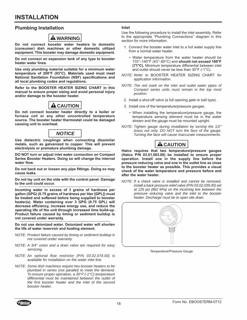
3. Install one of the temperature/pressure gauges.
• When installing the temperature/pressure gauge, thetemperature sensing element must be in the waterstream and the gauge must be mounted upright.
NOTE: Tighten gauge during installation by turning the 1/2"brass nut only. DO NOT turn the face of the gauge.Turning the face will cause inaccurate measurements.
Hatco requires that two temperature/pressure gauges(Hatco P/N 03.01.003.00) be installed to ensure properoperation. Install one in the supply line before thepressure reducing valve and one in the outlet line as closeto the booster heater as possible. This provides a visualcheck of the water temperature and pressure before andafter the water heater.
NOTE: If a check valve is installed and cannot be removed,install a back pressure relief valve (P/N 03.02.039.00) setat 125 psi (862 kPa) on the incoming line between thepressure reducing valve and the inlet to the boosterheater. Discharge must be to open site drain.
Temperature/Pressure Gauge
CAUTION

INSTALLATION
Form No. EBOOSTERm-0712 19
4. Install the pressure reducing valve if water pressureavailable to the booster heater inlet is over 25 psi (172 kPa).
• Set pressure reducing valve at 20 psi (138 kPa) flowpressure.
NOTE: Be sure water flows through the pressure reducingvalve in the proper direction. Check directional arrow.Valve will reduce pressure only during flow conditions.
If water supply pressure to the booster inlet is over 20 psi(138 kPa) during flow, install pressure reducing valve withbuilt-in bypass (Hatco P/N 03.02.004.00) for properoperation of dish machine rinse nozzles.
NOTE: The pressure reducing valve must be the type equippedwith a high pressure bypass, as supplied by Hatco.
Pressure Reducing Valve
5. Install the temperature/pressure relief valve.
• mini-Compact Series: P/N 03.02.020.00 • Compact and Imperial Series: P/N 03.02.022.00
Temperature/Pressure Relief Valve
CAUTION
Temperature/pressure protective equipment should notbe less than a combination temperature/pressure reliefvalve certified by a nationally recognized testinglaboratory that maintains periodic inspection of theproduction of this equipment and meets the requirementsfor Relief valves and Automatic Shutoff Devices for HotWater Supply Systems, ANSI z21.22-1979. Thetemperature/pressure relief valve must be marked with aminimum set pressure not to exceed the markedhydrostatic test pressure of the booster heater as notedon the unit specifications.
FOR INSTALLING PRESSURE AND TEMPERATURERELIEF vALvES IN ACCORDANCE WITH AMERICANNATIONAL STD. z21.22-1979. Combination pressure andtemperature relief valves with extension thermostats mustbe installed so that the temperature-sensing element isimmersed in the water within the top 6" (152 mm) of thetank. They must be installed directly in a tank tapping.Combination pressure and temperature relief valves thatdo not have extension elements must be mounted directlyin a tank tapping located within the top 6" (152 mm) of thetank, and shall be adequately insulated and located so asto assure isolation from ambient conditions that are notindicative of stored water temperature. TO AvOID WATERDAMAGE OR SCALDING DUE TO vALvE OPERATION,DRAIN PIPE MUST BE CONNECTED TO vALvE OUTLETAND RUN TO A SAFE PLACE OF DISPOSAL. Dischargeline must be as short as possible and be the same size asthe valve discharge connection throughout its entirelength. Drain line must pitch downward from the valve andmust terminate between 1-1/2" (38 mm) and 6" (152 mm)above the floor drain where any discharge will be clearlyvisible. The drain line shall terminate plain, not threaded,with material serviceable for temperatures up to 250°F(121°C) or greater. Excessive length, over 30' (9.1 m), oruse of more than four elbows can cause a restriction andreduce the discharge capacity of the valve. No shut-offvalve shall be installed between the relief valve and tank,or in the drain line. valve lever must be trippedperiodically to assure that waterways are clear. Thisdevice is designated for emergency safety relief and shallnot be used as an operating control. The valves are set torelieve at 150 psi (1034 kPa) or when water temperaturereaches 210°F (99°C). Read tag on valve for additionalinformation.
BURN HAzARD: valves supplied by Hatco are designedfor high temperature commercial operation. Do notsubstitute Hatco valves with valves designed for domesticwater heaters.
Do not use an anti-siphon or check valves on incomingwater line.
CAUTION
WARNING

INSTALLATION
Form No. EBOOSTERm-071220
Temperature/Pressure Gauge
Temperature/Pressure Gauge
Shock Absorberfor water hammer†
Outlet to Dishwasher
Discharge from T/P Valve.Air gap must complywith plumbing code.
3/4” Gate or Ball Valve‡
Water Inlet fromprimary water heater
Blended Phosphate WaterTreatment System†
Outlet
Drain Valve‡
3/4” Union‡
Back PressureRelief Valve†
Inlet
Floor Drain‡
Outlet
Inlet
NOTE: Centerline of booster “T” fitting mustnot extend closer than 102 mm (4″) to the floor.
Pressure Reducing Valvewith High Pressure By-pass(20 psi [138 kPa] flow pressure maximum)
Temperature/PressureRelief Valve, 150 PSI/210°F
(1040 kPa/99°C)
Temperature/Pressure Gauge
Temperature/Pressure Gauge
FloorDrain‡
Shock Absorberfor water hammer†
Outlet to Dishwasher
Discharge from T/P Valve.Air gap must complywith plumbing code.
3/4” Gate or Ball Valve‡
Water Inlet fromprimary water heater
Blended Phosphate WaterTreatment System†
Outlet3/4” Union‡
Back PressureRelief Valve†
Inlet
DrainValve‡
Pressure Reducing Valvewith High Pressure By-pass(20 psi [138 kPa] flow pressure maximum) Temperature/Pressure
Relief Valve, 150 PSI/210°F(1040 kPa/99°C)
NOTE: Centerline of booster “T” fitting mustnot extend closer than 102 mm (4″) to the floor.
Two Imperial models Connected in Series
Imperial “S” Series
† Not supplied, but is available as an option/accessory.
‡ Not supplied with booster heater.
Plumbing Connections
valves, gauges, and unions must be installed per diagramto ensure proper operation, servicing, and warrantycoverage.
WARNING

INSTALLATION
Form No. EBOOSTERm-0712 21
Temperature/Pressure Gauge
Pressure Reducing Valvewith High Pressure By-pass(20 psi [138 kPa] flow pressure maximum)Temperature/
Pressure Gauge
Shock Absorberfor water hammer†
Outlet to Dishwasher
Discharge from T/P Valve.Air gap must complywith plumbing code.
3/4” Gate or Ball Valve‡
Water Inlet fromprimary water
heater
Blended Phosphate WaterTreatment System†
Back PressureRelief Valve†
InletTemperature/PressureRelief Valve, 150 PSI/210°F(1040 kPa/99°C)
Flow Restrictor†
Floor Drain‡
Drain Valve‡NOTE: Centerline of booster “T” fitting mustnot extend closer than 102 mm (4″) to the floor.
Temperature/Pressure GaugeTemperature/
Pressure Gauge
Floor Drain‡
Shock Absorberfor water hammer†
Outlet to Dishwasher
Discharge from T/P Valve.Air gap must complywith plumbing code.
3/4” Gate or Ball Valve‡
Water Inlet fromprimary water heater
Blended Phosphate WaterTreatment System†
OutletBack PressureRelief Valve†
Inlet
Drain Valve‡
Pressure Reducing Valvewith High Pressure By-pass(20 psi [138 kPa] flow pressure maximum)
Temperature/PressureRelief Valve, 150 PSI/210°F(1040 kPa/99°C)
mini-Compact models
Compact Series
† Not supplied, but is available as an option/accessory.
‡ Not supplied with booster heater.
Plumbing Connections
valves, gauges, and unions must be installed per diagramto ensure proper operation, servicing, and warrantycoverage.
WARNING

INSTALLATION
Form No. EBOOSTERm-071222
Recommended Temperature/Pressure Gauge Installation
alternate Temperature/Pressure Gauge Installation
Hatco has always endorsed the use of safety equipmentwhen using a booster water heater or storage-type waterheater. Hatco booster heaters are shipped with atemperature/pressure relief valve at no extra charge. Thisvalve must be installed into the marked opening providedin the tank. valves supplied by Hatco are designed forhigh temperature commercial operation. Do not substituteHatco supplied valves with valves designed for domesticoperation.
It is essential to recognize that even though a water heatermay be properly installed initially and approved, therealways exists the possibility that unknowing individualsmight alter or change the installation in a manner thatwould render it unsafe. Therefore, it is important that allsafety programs provide some mechanism to assure thatthese installations are inspected periodically.
WARNING
Temperaturesensing element
Temperature/pressure gauge with 1/2” pipe thread
1/2” copper female fitting adapter
3/4” nominalcopper pipe
Temperaturesensing element
1/2” copper female fitting adapter
Temperature/pressure gauge with 1/2” pipe thread
3/4" nominal copper pipe
Center bottom of sensor
in copper pipe
3/4" x 1/2" x 3/4"copper tee
Outlet1. Flush the water supply line to remove any pipe compound
and foreign matter.
2. Connect the booster heater water outlet to the commercialdish machine sanitizing rinse pipe connection using a 3/4"union and piping.
DO NOT turn or adjust water outlet connection on LargeCompact Series units (C-24 to C-57).
NOTE: Red mark on water outlet pipe for C-24 to C-57 seriesunits must remain in the top most position.
NOTE: Be certain the connection is made to the final rinse andnot to the wash tank.
3. Install a temperature/pressure gauge in the outlet line. Thetemperature sensing element must be in the water streamand the gauge must be mounted upright.
• Water temperature at the outlet should be 185°–190°F(85°–88°C).
NOTE: Some dish machines require two booster heaters to beplumbed in series (not parallel) to meet the demand.To ensure proper operation, a 30°F (-1°C) temperaturedifferential must be maintained between the outlet ofthe first booster heater and the inlet of the secondbooster heater.
NOTE: Hatco recommends installing an optional shockabsorber (P/N 03.04.057.00) in the outlet line as closeas possible to the commercial dish machine solenoidrinse valve. The shock absorber softens the waterhammer caused by automatic dish machine valves.
Plumbing Installation Inspection1. Close the drain valve and fill the booster heater with water.
2. Check all pipe connections for leaks.
3. make sure the temperature/pressure relief valve dischargeis not blocked.
4. Vent air from the tank before operating by opening thetemperature/pressure relief valve.
DO NOT turn on power to the booster heater until tank hasbeen filled with water and all air has been vented throughthe dish machine rinse nozzle. The heating elements willburn out in seconds if operated when they are notimmersed in water.
NOTICE
CAUTION

INSTALLATION
Form No. EBOOSTERm-0712 23
Electrical Knockout
Electrical Knockouts
Electrical Knockout
Compact SeriesImperial Series Mini-Compact Series
Electrical — All Sizes and voltagesGeneralHatco Electric Booster Water Heaters are available for operationon standard power systems. Check the specification label forthe proper power supply.
all internal electrical connections have been made at thefactory. See the “Circuit Breaker and Fused Disconnect Switch”chart in the SPECIFICaTIONS section for supply wire size, fuse,breaker, and conduit recommendations. Consult local codes forverification and compliance.
ELECTRIC SHOCK HAzARD:• Unit must be installed by qualified, trained installers.
Installation must conform to all local electrical andplumbing codes. Installation by unqualified personnelwill void the unit warranty and may lead to electricshock or burn, as well as damage to unit and/or itssurroundings. Check with local plumbing and electricalinspectors for proper procedures and codes.
• Turn OFF power at fused disconnect switch/circuitbreaker and allow unit to cool before performing anycleaning, adjustments, or maintenance.
• Consult a licensed electrical contractor for properelectrical installation conforming to local electricalcodes and the National Electrical Code (N.E.C.).
Units are voltage-specific. Refer to specification label forelectrical requirements before beginning installation.Connecting unit to incorrect power supply will voidproduct warranty and may damage unit.
NOTICE
WARNING
Electrical Connections1. Remove the front jacket cover screws, pull the cover
forward and remove the cover.
NOTE: On Imperial models, there is a hinged access panelunder the front jacket cover. Remove the bottom screwand lift the panel up to expose the fuse blocks.
• On mini-Compact models, remove front cover screws.Ease cover forward and upward.
• On Compact models, the control box is under the fronthinged jacket cover.
2. Locate the heater terminal or fuse block(s) inside the unit.
NOTE: See “Circuit Breaker and Fused Disconnect Switch”chart in the SPECIFICaTIONS section for properconnections and wire size.
NOTE: Only 6, 7, and 9 kW models, in 208 or 240 volt, can beconverted to single or three phase in the field. Refer tothe wiring diagram for proper wiring connections at theterminal block.
3. Bring power leads from a properly sized disconnect switchor circuit breaker through the knockout provided on theunit. Connect leads to the terminal or fuse block(s). USE COPPER WIRE ONLy. TIGHTEN CONNECTIONSPROPERLy TO A MINIMUM OF 40 INCH POUNDS.
NOTE: Due to the rigors of transportation all connectionsshould be checked for tightness before heater is putinto operation.
4. Properly connect an equipment grounding connector to thegrounding lug (located near the supply terminals).
DO NOT turn on power to the booster heater until tank hasbeen filled with water and all air has been vented throughthe dish machine rinse nozzles. Heating elements willburn out in seconds if operated when not immersed inwater.
5. Replace and secure cover(s).
CAUTION
Electrical Knockout Locations
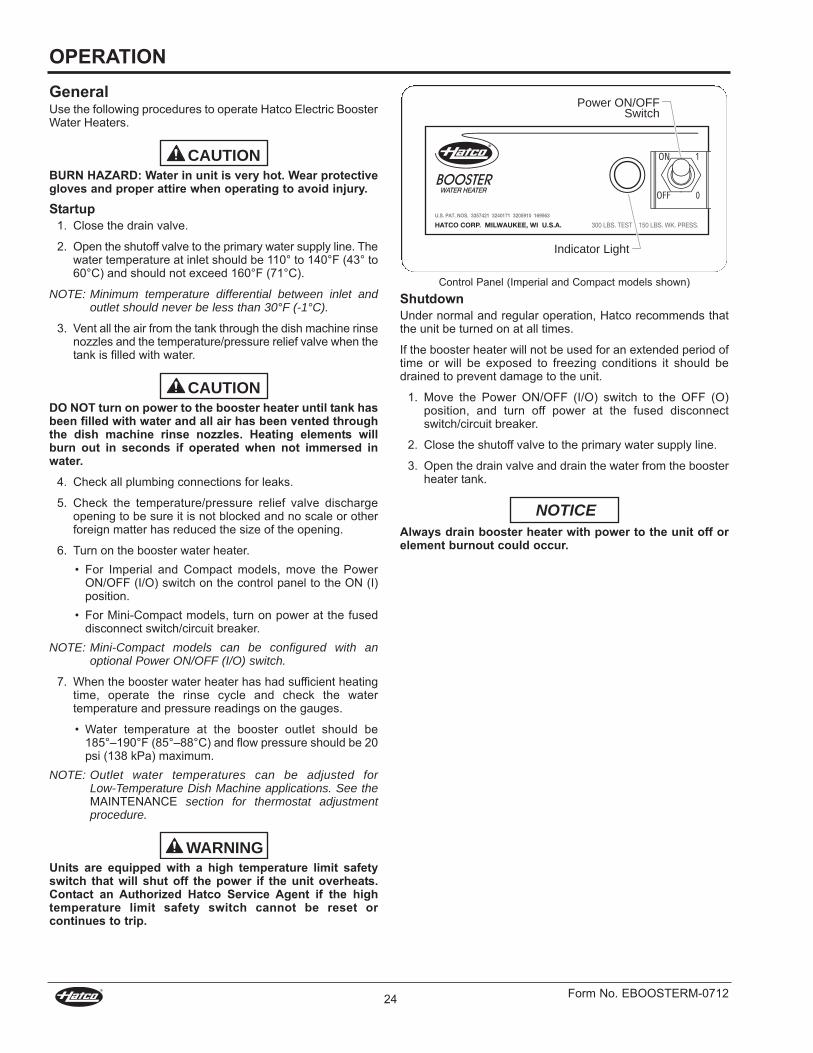
OPERATION
Form No. EBOOSTERm-071224
GeneralUse the following procedures to operate Hatco Electric BoosterWater Heaters.
BURN HAzARD: Water in unit is very hot. Wear protectivegloves and proper attire when operating to avoid injury.Startup
1. Close the drain valve.
2. Open the shutoff valve to the primary water supply line. Thewater temperature at inlet should be 110° to 140°F (43° to60°C) and should not exceed 160°F (71°C).
NOTE: Minimum temperature differential between inlet andoutlet should never be less than 30°F (-1°C).
3. Vent all the air from the tank through the dish machine rinsenozzles and the temperature/pressure relief valve when thetank is filled with water.
DO NOT turn on power to the booster heater until tank hasbeen filled with water and all air has been vented throughthe dish machine rinse nozzles. Heating elements willburn out in seconds if operated when not immersed inwater.
4. Check all plumbing connections for leaks.
5. Check the temperature/pressure relief valve dischargeopening to be sure it is not blocked and no scale or otherforeign matter has reduced the size of the opening.
6. Turn on the booster water heater.• For Imperial and Compact models, move the Power
ON/OFF (I/O) switch on the control panel to the ON (I)position.
• For mini-Compact models, turn on power at the fuseddisconnect switch/circuit breaker.
NOTE: Mini-Compact models can be configured with anoptional Power ON/OFF (I/O) switch.
7. When the booster water heater has had sufficient heatingtime, operate the rinse cycle and check the watertemperature and pressure readings on the gauges.
• Water temperature at the booster outlet should be185°–190°F (85°–88°C) and flow pressure should be 20psi (138 kPa) maximum.
NOTE: Outlet water temperatures can be adjusted for Low-Temperature Dish Machine applications. See themaINTENaNCE section for thermostat adjustmentprocedure.
Units are equipped with a high temperature limit safetyswitch that will shut off the power if the unit overheats.Contact an Authorized Hatco Service Agent if the hightemperature limit safety switch cannot be reset orcontinues to trip.
WARNING
CAUTION
CAUTION
Control Panel (Imperial and Compact models shown)ShutdownUnder normal and regular operation, Hatco recommends thatthe unit be turned on at all times.
If the booster heater will not be used for an extended period oftime or will be exposed to freezing conditions it should bedrained to prevent damage to the unit.
1. move the Power ON/OFF (I/O) switch to the OFF (O)position, and turn off power at the fused disconnectswitch/circuit breaker.
2. Close the shutoff valve to the primary water supply line.
3. Open the drain valve and drain the water from the boosterheater tank.
Always drain booster heater with power to the unit off orelement burnout could occur.
NOTICE
Power ON/OFFSwitch
Indicator Light

MAINTENANCE
Form No. EBOOSTERm-0712 25
High Temperature Limit Safety Switchall Hatco Electric Booster Water Heaters are equipped with amanually reset high temperature limit safety switch. If thetemperature of the water in the heater exceeds 210°F (99°C)the safety switch will shut off the power. The switch must bemanually reset.
If the high temperature limit safety switch needs to be reset usethe following procedure:
1. move the Power ON/OFF (I/O) switch to the OFF (O)position and unplug the unit from the power source.
2. Remove the access cover.
3. Push the red reset button.
4. If tripping repeats, call an authorized Service agent.
Thermostat adjustment and High Temperature Limit Safety Switch
Front View of Thermostat
Adjustment Screws
Access Cover
InnerScrew
OuterScrew
High Limit SwitchReset Button
ThermostatAdjustment Screw
ThermostatAdjustment Screw
GeneralElectric Booster Water Heaters are designed for maximumdurability and performance with minimum maintenance.
ELECTRIC SHOCK HAzARD:• Turn OFF power at fused disconnect switch/circuit
breaker and allow unit to cool before performing anycleaning, adjustments, or maintenance.
• DO NOT submerge or saturate with water. Unit is notwaterproof. Do not operate if unit has been submergedor saturated with water.
• Do not steam clean or use excessive water on unit.• Do not clean unit when it is energized or hot.• This unit must be serviced by qualified personnel only.
Service by unqualified personnel may lead to electricshock or burn.
• Use only Genuine Hatco Replacement Parts whenservice is required. Failure to use Genuine HatcoReplacement Parts will void all warranties and maysubject operators of the equipment to hazardouselectrical voltage, resulting in electrical shock or burn.Genuine Hatco Replacement Parts are specified tooperate safely in the environments in which they areused. Some aftermarket or generic replacement partsdo not have the characteristics that will allow them tooperate safely in Hatco equipment.
This unit has no “user-serviceable” parts. If service isrequired on this unit, contact an Authorized Hatco ServiceAgent or contact the Hatco Service Department at 800-558-0607 or 414-671-6350; fax 800-690-2966; orInternational fax 414-671-3976.
Thermostat AdjustmentThe thermostat is factory calibrated at 185°–190°F (85°–88°C).If adjustment or recalibration is required due to the rigors oftransportation, use the following procedure.
NOTE: Low temperature dish machines require the thermostat(s)to be adjusted to 140°–150°F (60°–66°C).
1. move the Power ON/OFF (I/O) switch to the OFF (O)position and unplug the unit from the power source.
2. Remove the access cover.
3. adjust the temperature setpoint to the desired temperature.
• To lower the temperature setpoint, turn the outer screwcounterclockwise.
• To raise the temperature setpoint, turn the outer screwclockwise.
NOTE: 1/6 turn of the outer screw equals 12°F (6.7°C).
NOTE: If recalibration is necessary, with the outer screw athigh stop, turn the inner screw clockwise to raise theset point.
NOTE: 1/6 turn of the inner screw equals 8°F (4.4°C).
WARNING

OPTIONS AND ACCESSORIES
Form No. EBOOSTERm-071226
Stainless Steel Adjustable LegsStainless steel adjustable legs (P/N 05.30.070.00) are availableas accessories for all models.
Use the following procedure to install legs:
1. Carefully place unit on its side.
Do not lay unit on the side with the control panel. Damageto the unit could occur.
2. Thread the adjustable legs into the existing leg holes onthe bottom of the unit.
3. after all legs are secure, return the unit to the uprightposition.
NOTE: If unit is not level, use an adjustable wrench to adjustthe foot of each leg until unit is level. Each leg isadjustable from 6" (152 mm) to 7" (178 mm).
Stainless Steel adjustable Legs
Floor Mounting LegsStainless steel adjustable legs with deck mounting flangessecure the booster heater to the floor are available options forCompact and Imperial models only.
Mounting Slide Bracketsa set of optional mounting slide brackets is available forCompact models only. (P/N R04.20.030.00)
Plumbing Accessoriesa shock absorber, a brass pressure reducing valve, and a backpressure relief valve are available as accessories.
Plumbing accessories
AdjustableFoot
NOTICE
Brass Pressure Reducing Valve
(P/N 03.02.015.00)
Back Pressure Relief Valve*
(P/N 03.02.039.00)
*Not available for Mini-Compact models.
Shock Absorber(P/N 03.40.057.00)
Blended Phosphate Water Treatment SystemThe optional Blended Phosphate Water Treatment System (P/N 03.05.061.00) dispenses a small amount of polyphosphateinto the water. The polyphosphate prevents the buildup ofmineral molecules.
The optional blended phosphate water treatment system isinstalled with unions on the incoming 3/4" water supply line afterthe pressure reducing valve and before the booster heater.Replacing a Phosphate Cartridge(P/N 03.05.061A.00) Cartridges supplied have a usage rating of 100,000 gallons(378,541 liters) of water. To ensure proper operation, thecartridges must be replaced when the compound is near thebottom of the cartridge.
Use the following procedure for replacement:
1. move the ON/OFF (I/O) switch to the OFF (O) position.2. Shut off water supply and open the drain valve to remove
water in piping.
3. Loosen the canister using the attached wrench.
4. Remove canister and discard depleted cartridge.
5. Using a clean damp cloth, wipe the interior of the canisterclean.
NOTE: Make sure the O-ring seal is placed properly in thecanister.
6. Reverse the above procedure to reinstall.
NOTE: Product failure caused by liming or sediment buildup isnot covered under warranty.
Blended Phosphate Water Treatment System
Stainless Body and Basean optional stainless body and base is available for all models.
Security Packagea security package is a factory-installed option for Compact andImperial models only. a security package contains Torx® screwsand a control cover.
Canister
Wrench

TROUBLESHOOTING GUIDE
Form No. EBOOSTERm-0712 27
IMPORTANT! Read Before Using theTroubleshooting Guidemany times when a booster heater does not appear to befunctioning properly, the fault is not with the booster heater itselfbut with factors outside the heater.
ELECTRIC SHOCK HAzARD:• Turn OFF power at fused disconnect switch/circuit
breaker and allow unit to cool before performing anycleaning, adjustments, or maintenance.
• This unit must be serviced by qualified personnel only.Service by unqualified personnel may lead to electricshock or burn.
Before proceeding with the “Troubleshooting Guide” to diagnosean issue, check aLL of the following outside factors.Water Temperature
• Check the temperature of the water feeding into thebooster tank. It must be 110° to 140°F (43° to 60°C),depending on the heating capability of the unit. The inletwater supply must be of sufficient quantity to hold itstemperature throughout the dishwashing operation.
• If the wash tank of the dish machine is filled through thebooster heater, this will use up all of the 180°F (82°C) waterin storage. Sufficient time must be allowed to reheat thewater in storage before starting the dish machine.
• Primary water heater temperature should not exceed 160°F(71°C).
Water Pressure• Water pressure at the inlet to the booster heater must be
adequate for proper operation of the rinse cycle of the dishmachine, not to exceed 20 psi (138 kPa). Check with dishmachine manufacture for specific details.
• If incoming water exceeds 20 psi (138 kPa), a pressurereducing valve must be installed.
WARNING
Electrical Connections• Booster heater voltage must be correct for voltage
available. Check the specification label on the boosterheater for full information.
• The breakers or fuses mUST be properly sized.Plumbing Connections
• The temperature/pressure relief valve must be properlyinstalled and be supplied by Hatco.
• a check valve should not be installed ahead of the booster.
NOTE: If a check valve is installed and cannot be removed,install a back pressure relief valve (P/N 03.02.039.00) setat 125 psi (862 kPa) on the incoming line between thepressure reducing valve and the inlet to the boosterheater. Discharge must be to open site drain.
If the unit does not function properly after performing thesechecks, continue to the “Troubleshooting Guide” in this section.

Symptom Probable Cause Corrective Action
Water reaches 180°F (82°C) butdoes not last through the entiredish machine operation.
Low incoming water temperature. Incoming water temperature must beadequate for booster size. Increase incomingwater temperature.
Incoming water temperature drops. Primary water supply is not adequate toprovide correct temperature in sufficientquantities. Increase supply of primary hotwater.
Flow pressure is too high. Higher pressure uses an excessive quantity ofhot water. adjust flow pressure to 20 psi (138kPa).
Booster heater may be undersized. Booster heater must be properly sized forincoming water temperature and rinserequirements of the dish machine.
Incorrect voltage. Check voltage on heater serial plate and makesure supplied voltage matches. a 240Vbooster heater operating on 208V reduceswattage to 76% efficiency.
The booster heater does notheat at all or only delivers waterat 120°- 150°F (49°-66°C).
Unit may have been energized withoutwater (dry fired) causing the element(s) toburn out quickly.
Replace the element(s).
Fuses may be blown or circuit breakertripped.
Check for proper fuse sizing. Replace fuses.Check/reset circuit breaker.
Over-current fuses may be blown. Check for shorted elements, bad fuse block orshort in wiring.
Temperature setting out of calibration orinoperable.
Temperature setting should be maximum of190°F (88°C).
Contactors do not pull in. Test for voltage at coils. If coils are open orshorted, replace contactors.
High limit switch may be tripped ordefective.
Reset switch, refer to “High Temperature LimitSafety Switch” in the maINTENaNCE section.If switch continues to trip or cannot be resetcontact an authorized Service agent.
Transformer not working properly. Check secondary voltage, it should be thesame as the control circuit voltage. If not,replace the transformer.
Low water cutoff inoperable, contacts donot close.
Remove probe wire and touch it to the tank. Ifcontacts close, probe is fouled and must becleaned or replaced.
Relay on circuit board maybe defective.Jumper terminals 6 and 7. If unit energizes,circuit board is defective and should bereplaced.
TROUBLESHOOTING GUIDE
Form No. EBOOSTERm-071228
This unit must be serviced by qualified personnel only.Service by unqualified personnel may lead to electricshock or burn.
WARNINGELECTRIC SHOCK HAzARD: Turn OFF power at fuseddisconnect switch/circuit breaker and allow unit to coolbefore performing any cleaning, adjustments, ormaintenance.
WARNING

Symptom Probable Cause Corrective Action
Water at dish machine is not atthe proper temperature.
Gauge(s) not working properly. Check temperature of water with athermometer to be certain gauges are workingcorrectly. If not, replace gauge(s).
Thermostat set too low. adjust or recalibrate, refer to “Thermostatadjustment” in the maINTENaNCE section. Ifthermostat will not recalibrate properly,replace it.
Booster heater has more than (5) linear feet(1524 mm) of water pipe to the dishmachine, causing the water to cool offinside the pipe.
If located farther than 5 linear feet (1524 mm),pipes should be wrapped in insulation, and/ora recirculating system installed.
Heating element(s) burn out. Tank inadvertently drained leavingelement(s) in a dry condition.
Replace element(s), and make sure tank is fullof water at all times. Check low water cut-offsystem for proper operation.
Lime buildup in tank causing element(s) tosplit and burn out.
Replace element(s), and clean or delime tanksperiodically. a water softener or blendedphosphate treatment system may be required.
Relief valve dribbles. No pressure reducing valve installed orincorrect valve installed causing pressurebuild-up inside booster tank.
a pressure reducing valve with high pressurebypass must be installed in the incoming waterline to allow water to expand back into thefeed line.
Bypass in pressure reducing valve may beblocked.
Clean bypass or replace with new valve withbuilt in bypass.
Check valve or anti-siphon valve installed inthe feed line.
Remove check valve or anti-siphon valve toallow for water expansion or install a backpressure relief valve (P/N 03.02.039.00) onthe incoming water line.
Relief valve opens. Unit is overheating. Thermostat may be set too high or is sticking.Recalibrate or replace the thermostat.
Contactor may be sticking in closedposition not allowing unit to cycle off.
Replace contactor(s).
High temperature limit safetyswitch trips.
Temperature limit safety switch is defective. If booster heater is not overheating, replaceHigh Limit Safety Switch.
Thermostat set too high. adjust or recalibrate, refer to “Thermostatadjustment” in the maINTENaNCE section.
Incoming water temperature too highcausing nuisance tripping of hightemperature limit switch.
Incoming water temperature should not behigher than 160°F (71°C).
Chattering contactor or lowwater cutoff circuit board
Loose connections or wire connection hasinsulation under crimp.
Tighten all connections and check crimps
Low voltage. Check control circuit voltage or secondaryvoltage with transformer.
Probe may be fouled. Bypass probe by removing wire from lowwater cutoff probe and grounding to tank.Clean or replace probe if chattering stops.
Contactor(s) may be bad. Test contactor coils and replace if needed.
TROUBLESHOOTING GUIDE
Form No. EBOOSTERm-0712 29

LIMITED WARRANTy
Form No. EBOOSTERm-071230
1. PRODUCT WARRANTyHatco warrants the products that it manufactures (the“Products”) to be free from defects in materials andworkmanship, under normal use and service, for a period of one(1) year from the date of purchase when installed andmaintained in accordance with Hatco’s written instructions or18 months from the date of shipment from Hatco. Buyer mustestablish the Product’s purchase date by registering the Productwith Hatco or by other means satisfactory to Hatco in its solediscretion.
Hatco warrants the following Product components to be freefrom defects in materials and workmanship from the date ofpurchase (subject to the foregoing conditions) for the period(s)of time and on the conditions listed below:a) One (1) year Parts and Labor PLUS One (1) Additional
year Parts-Only Warranty:Conveyor Toaster Elements (metal sheathed)Drawer Warmer Elements (metal sheathed)Drawer Warmer Drawer Rollers and SlidesStrip Heater Elements (metal sheathed)Display Warmer Elements (metal sheathed air heating)Holding Cabinet Elements (metal sheathed air heating)Heated Well Elements — HWB Series (metal sheathed)
b) One (1) year Parts and Labor PLUS Four (4) years Parts-Only Warranty:3CS and FR Tanks
c) One (1) year Parts and Labor PLUS Nine (9) years Parts-Only Warranty on:Electric Booster Heater TanksGas Booster Heater Tanks
d) Ninety (90) Day Parts-Only Warranty: Replacement Parts
THE FOREGOING WaRRaNTIES aRE EXCLUSIVE aND INLIEU OF aNY OTHER WaRRaNTY, EXPRESSED ORImPLIED, INCLUDING BUT NOT LImITED TO aNY ImPLIEDWaRRaNTY OF mERCHaNTaBILITY OR FITNESS FOR aPaRTICULaR PURPOSE OR PaTENT OR OTHERINTELLECTUaL PROPERTY RIGHT INFRINGEmENT.Without limiting the generality of the foregoing, SUCHWaRRaNTIES DO NOT COVER: Coated incandescent lightbulbs, fluorescent lights, heat lamp bulbs, coated halogen lightbulbs, halogen heat lamp bulbs, xenon light bulbs, LED lighttubes, glass components, and fuses; Product failure in boostertank, fin tube heat exchanger, or other water heating equipmentcaused by liming, sediment buildup, chemical attack, orfreezing; or Product misuse, tampering or misapplication,improper installation, or application of improper voltage.2. LIMITATION OF REMEDIES AND DAMAGESHatco’s liability and Buyer’s exclusive remedy hereunder will belimited solely, at Hatco’s option, to repair or replacement usingnew or refurbished parts or Product by Hatco or a Hatco-authorized service agency (other than where Buyer is locatedoutside of the United States, Canada, United Kingdom, oraustralia, in which case Hatco’s liability and Buyer’s exclusiveremedy hereunder will be limited solely to replacement of partunder warranty) with respect to any claim made within theapplicable warranty period referred to above. Hatco reservesthe right to accept or reject any such claim in whole or in part.In the context of this Limited Warranty, “refurbished” means apart or Product that has been returned to its originalspecifications by Hatco or a Hatco-authorized service agency.Hatco will not accept the return of any Product without priorwritten approval from Hatco, and all such approved returns shallbe made at Buyer’s sole expense. HaTCO WILL NOT BELIaBLE, UNDER aNY CIRCUmSTaNCES, FORCONSEQUENTIaL OR INCIDENTaL DamaGES, INCLUDINGBUT NOT LImITED TO LaBOR COSTS OR LOST PROFITSRESULTING FROm THE USE OF OR INaBILITY TO USE THEPRODUCTS OR FROm THE PRODUCTS BEINGINCORPORaTED IN OR BECOmING a COmPONENT OFaNY OTHER PRODUCT OR GOODS.

NOTES
Form No. EBOOSTERm-0712 31

Printed in U.S.a. July 2012 P/N 07.04.111.00 Form No. EBOOSTERm-0712
HATCO AUTHORIzED PARTS DISTRIBUTORS
HATCO CORPORATIONP.O. Box 340500
Milwaukee, WI 53234-0500 U.S.A.(800) 558-0607 (414) 671-6350
Parts and Service Fax (800) 690-2966International Fax (414) [email protected]
www.hatcocorp.com
ALABAMAJones mcLeod appl. Svc.Birmingham 205-251-0159
ARIzONAService Solutions GroupPhoenix 602-234-2443Byassee Equipment Co.Phoenix 602-252-0402
CALIFORNIAIndustrial ElectricCommercial Parts & Service, Inc.Huntington Beach 714-379-7100Chapman appl. ServiceSan Diego 619-298-7106P & D applianceCommercial Parts & Service, Inc.S. San Francisco 650-635-1900
COLORADOHawkins Commercial applianceEnglewood 303-781-5548
FLORIDAWhaley Foodservice RepairJacksonville 904-725-78003Wire Nass Service Co., Inc.Orlando 407-425-2681B.G.S.I.Pompano Beach 954-971-0456Comm. appliance ServiceTampa 813-663-0313
GEORGIATWC Servicesmableton 770-438-9797Heritage Service GroupNorcross 866-388-9837Southeastern Rest. Svc.Norcross 770-446-6177
HAWAIIBurney’s Comm. Service, Inc.Honolulu 808-848-1466Food Equip Parts & ServiceHonolulu 808-847-4871
ILLINOISParts TownLombard 708-865-7278Eichenauer Elec. ServiceDecatur 217-429-4229midwest Elec. appl. ServiceElmhurst 630-279-8000Cone’s Repair Servicemoline 309-797-5323
INDIANAGCS ServiceIndianapolis 317-545-9655
IOWAElectric motor Service Co.Davenport 319-323-1823Goodwin Tucker GroupDes moines 515-262-9308
KENTUCKyService Solutions GroupLexington 859-254-8854Service Solutions GroupLouisville 502-451-5411
LOUISIANAChandlers Parts & ServiceBaton Rouge 225-272-6620
MARyLANDElectric motor ServiceBaltimore 410-467-8080GCS ServiceSilver Spring 301-585-7550
MASSACHUSETTSace Service Co., Inc.Needham 781-449-4220
MICHIGANBildons appliance ServiceDetroit 248-478-3320Commercial Kitchen ServiceBay City 517-893-4561midwest Food Equip. ServiceGrandville 616-261-2000
MINNESOTAGCS ServicePlymouth 800-345-4221
MISSOURIGeneral PartsKansas City 816-421-5400Commercial Kitchen ServicesSt. Louis 314-890-0700Kaemmerlen Parts & ServiceSt. Louis 314-535-2222
NEBRASKAanderson ElectricOmaha 402-341-1414
NEvADABurney’s CommercialLas Vegas 702-736-0006Hi. Tech Commercial ServiceN. Las Vegas 702-649-4616
NEW JERSEyJay Hill RepairFairfield 973-575-9145Service PlusFlanders 973-691-6300
NEW yORKacme american Repairs, Inc.Brooklyn 718-456-6544alpro Service Co.Brooklyn 718-386-2515appliance InstallationBuffalo 716-884-7425Duffy’s Equipment Services, Inc.Buffalo 800-836-10143Wire NorthernPlattsburgh 800-634-5005Duffy’s Equipment Services, Inc.Sauquoit 800-836-1014J.B. Brady, Inc.Syracuse 315-422-9271
NORTH CAROLINAauthorized applianceCharlotte 704-377-4501
OHIOakron/Canton Comm. Svc. Inc.akron 330-753-6635Service Solutions GroupCincinnati 513-772-6600Commercial Parts and ServiceColumbus 614-221-0057Electrical appl. Repair ServiceBrooklyn Heights 216-459-8700E. a. Wichman Co.Toledo 419-385-9121
OKLAHOMAHagar Rest. Service, Inc.Oklahoma City 405-235-2184Krueger, Inc.Oklahoma City 405-528-8883
OREGONRon’s Service, Inc.Portland 503-624-0890
PENNSyLvANIAElmer Schultz ServicesPhiladelphia 215-627-5401FaST Comm. appl. ServicePhiladelphia 215-288-4800appliance Installation & ServicePittsburgh 412-809-0244K & D Service Co.Harrisburg 717-236-9039Electric Repair Co.Reading 610-376-5444
RHODE ISLANDmarshall Electric Co.Providence 401-331-1163
SOUTH CAROLINAWhaley Foodservice RepairW. Columbia 803-791-4420
TENNESSEECamp Electricmemphis 901-527-7543
TExASGCS ServiceFort Worth 800-433-1804armstrong Repair ServiceHouston 713-666-7100Cooking Equipment Specialistmesquite 888-866-9276Refrigerated Specialist, Inc.mesquite 888-866-9276Commercial Kitchen Repair Co.San antonio 210-735-2811
UTAHLa monica’s Rest. Equip. Servicemurray 801-263-3221
vIRGINIADaubersNorfolk 757-855-4097DaubersSpringfield 703-866-3600
WASHINGTON3Wire Restaurant applianceSeattle 800-207-3146
WISCONSINa.S.C., Inc.madison 608-246-3160a.S.C., Inc.milwaukee 414-543-6460
CANADAALBERTAKey Food Equipment ServiceEdmonton 780-438-1690
BRITISH COLUMBIAKey Food Equipment ServiceVancouver 604-433-4484Key Food Equipment ServiceVictoria 250-920-4888
MANITOBAair Rite, Inc.Winnipeg 204-895-2300
NEW BRUNSWICKEmR Services, Ltd.moncton 506-855-4228
ONTARIOR.G. Henderson Ltd.Toronto 416-422-5580Choquette - CKS, Inc.Ottawa 613-739-8458
QUÉBECChoquette - CKS, Inc.montreal 514-722-2000Choquette - CKS, Inc.Québec City 418-681-3944
UNITED KINGDOMmarren GroupNorthants +44(0)1933 666233
Register your unit online!See ImPORTaNT OWNER INFORmaTION
section for details.