electric auxiliary power supply and battery system for ... · st v2.0 electric auxiliary power...
TRANSCRIPT
Sup
erse
ded
by T
HR
RS
100
01 S
T v2
.0
Electric Auxiliary Power Supply and Battery System for Passenger Rolling Stock
T HR RS 10001 ST
Standard
Version 1.0
Issued Date: 23 September 2014
Important Warning This document is one of a set of standards developed solely and specifically for use on the rail network owned or managed by the NSW Government and its agencies. It is not suitable for any other purpose. You must not use or adapt it or rely upon it in any way unless you are authorised in writing to do so by a relevant NSW Government agency. If this document forms part of a contract with, or is a condition of approval by, a NSW Government agency, use of the document is subject to the terms of the contract or approval. This document may not be current. Current standards are available for download from the Asset Standards Authority website at www.asa.transport.nsw.gov.au. © State of NSW through Transport for NSW

Sup
erse
ded
by T
HR
RS
100
01 S
T v2
.0
T HR RS 10001 ST Electric Auxiliary Power Supply and Battery System for Passenger Rolling Stock
Version 1.0 Issued Date: 23 September 2014
© State of NSW through Transport for NSW
Standard governance
Owner: Lead Rolling Stock Engineer, Asset Standards Authority
Authoriser: Chief Engineer Rail, Asset Standards Authority
Approver: Director, Asset Standards Authority on behalf of ASA Configuration Control Board
Document history
Version Summary of change
1.0 First issue
For queries regarding this document, please email the ASA at
or visit www.asa.transport.nsw.gov.au

Sup
erse
ded
by T
HR
RS
100
01 S
T v2
.0
T HR RS 10001 ST Electric Auxiliary Power Supply and Battery System for Passenger Rolling Stock
Version 1.0 Issued Date: 23 September 2014
© State of NSW through Transport for NSW Page 3 of 15
Preface
The Asset Standards Authority (ASA) is an independent unit within Transport for NSW (TfNSW)
and is the network design and standards authority for defined NSW transport assets.
The ASA is responsible for developing engineering governance frameworks to support industry
delivery in the assurance of design, safety, integrity, construction, and commissioning of
transport assets for the whole asset life cycle. To achieve this, the ASA effectively discharges
obligations as the authority for various technical, process, and planning matters across the
asset life cycle.
The ASA collaborates with industry using stakeholder engagement activities to assist in
achieving its mission. These activities help align the ASA to broader government expectations of
making it clearer, simpler, and more attractive to do business within the NSW transport industry,
allowing the supply chain to deliver safe, efficient, and competent transport services.
The ASA develops, maintains, controls, and publishes a suite of standards and other
documentation for transport assets of TfNSW. Further, the ASA ensures that these standards
are performance based to create opportunities for innovation and improve access to a broader
competitive supply chain.
This document provides the requirements for electrical auxiliary power supply and battery
system for heavy rail passenger rolling stock and aims to ensure the reliability, availability,
maintainability, and safety of such systems.
This standard is developed by the Asset Standards Authority Chief Engineer Rail and has been
reviewed by TfNSW and industry.
It is a first issue.

Sup
erse
ded
by T
HR
RS
100
01 S
T v2
.0
T HR RS 10001 ST Electric Auxiliary Power Supply and Battery System for Passenger Rolling Stock
Version 1.0 Issued Date: 23 September 2014
© State of NSW through Transport for NSW Page 4 of 15
Table of contents
1. Introduction............................................................................................................................................5
2. Purpose...................................................................................................................................................5 2.1. Scope ..................................................................................................................................................................... 5 2.2. Application............................................................................................................................................................. 5
3. Reference documents ...........................................................................................................................5
4. Terms and definitions ...........................................................................................................................6
5. Electrical auxiliary power supply system ...........................................................................................8 5.1. EAPS protection.................................................................................................................................................... 8 5.2. EAPS voltages....................................................................................................................................................... 9 5.3. Fixed shore power supply interface .................................................................................................................. 10 5.4. EAPS redundancy ............................................................................................................................................... 10 5.5. General power outlets......................................................................................................................................... 11
6. Battery systems ...................................................................................................................................11 6.1. Battery systems mechanical requirements ...................................................................................................... 12 6.2. Battery management and charging system ...................................................................................................... 12 6.3. Battery capacity and emergency load duration................................................................................................ 13 6.4. Energy storage device requirements ................................................................................................................ 14

Sup
erse
ded
by T
HR
RS
100
01 S
T v2
.0
T HR RS 10001 ST Electric Auxiliary Power Supply and Battery System for Passenger Rolling Stock
Version 1.0 Issued Date: 23 September 2014
© State of NSW through Transport for NSW Page 5 of 15
1. Introduction
The electrical auxiliary power supply (EAPS) system covers the equipment that converts the
train's main power supply input voltage to voltages for the train's auxiliary systems such as the
climate control system, train control and lighting circuits.
The battery system covers the equipment that stores and provides emergency power to
maintain power to essential auxiliary systems when the main power supply is not available.
The requirements in this standard are based on international standards and local performance
criteria that are currently met by existing TfNSW passenger rolling stock fleet.
2. Purpose
This document provides the minimum performance requirements and recommendations for the
electrical auxiliary power supply and battery systems for TfNSW passenger rolling stock.
Requirements for EAPS and battery systems were previously included in contract technical
performance specifications for rolling stock procurement programs.
This standard aims to ensure the reliability, availability, maintainability, and safety of the
electrical auxiliary power supply and battery systems used in passenger rolling stock in NSW.
This standard also seeks to reduce the whole of life cost of the battery system.
2.1. Scope
This document covers the requirements of the auxiliary power supply and backup power supply
system for electric passenger rolling stock operating on TfNSW's heavy rail network.
This document shall be used in conjunction with the technical specification for compliance for
new rolling stock.
2.2. Application
This standard applies to the design or procurement of new electric heavy rail passenger rolling
stock and may be used for the redesign of existing rolling stock assets that undergo a
refurbishment or modification program, as directed by the TfNSW contract administrator.
3. Reference documents
International standards
IEC 61287 Railway Applications - Power converters installed on board rolling stock
IEC 60146 Semiconductor converters - General requirements and line commutated converters
EN 50155 Railway Applications - Electronic Equipment Used on Rolling Stock
Sup
erse
ded
by T
HR
RS
100
01 S
T v2
.0
T HR RS 10001 ST Electric Auxiliary Power Supply and Battery System for Passenger Rolling Stock
Version 1.0 Issued Date: 23 September 2014
© State of NSW through Transport for NSW Page 6 of 15
EN 50153 Railway Applications - Rolling Stock - Protective Provisions Relating To Electrical
Hazards
EN 61373 Railway Applications - Rolling Stock Equipment - Shock and Vibration Tests
I.S.EN 13272Railway Applications - Electrical Lighting for Rolling Stock in Public Transport
Systems
IEC 60529 Degrees of protection provided by enclosures (IP Code)
Australian standards
AS/NZS 3112 Approval and test specification - Plugs and socket-outlets
AS 61000.3.100 Electromagnetic compatibility (EMC) - Limits - Steady state voltage limits in
public electricity systems
Transport for NSW standards
T HR RS 00117 ST Electric Circuits and Equipment for Passenger Rolling Stock
T HR RS 01701 ST Mounting and Installation of Electrical Equipment
T HR RS 12001 ST Interior and Exterior Lighting for Passenger Rolling Stock
ESR 0001-E Minimum Operating Standards for Rolling Stock - RSU Appendix E - Specification
for 1500 V dc Traction Supply
T HR RS 08001 ST Interior Climate Comfort for Passenger Rolling Stock
T HR TE 41001 ST Packet switched networks – wired – local, metropolitan and wide area
networks
T MU AM 01001 ST Life Cycle Costing
Drawings
Title: "Carriage Inspection Shed 415 Volt Train Supply Main Switchboard Arrangement and
Control Diagram", EDMS Number: EL0012182, Original SRA Drawing Number: C83656
4. Terms and definitions
The following terms and definitions apply in this document:
ac alternating current
battery an individual self-contained energy storage device
battery bank a group of individual batteries connected in series or parallel to achieve the
required voltage
control circuits all circuits related to the control of train systems and auxiliary equipments
Sup
erse
ded
by T
HR
RS
100
01 S
T v2
.0
T HR RS 10001 ST Electric Auxiliary Power Supply and Battery System for Passenger Rolling Stock
Version 1.0 Issued Date: 23 September 2014
© State of NSW through Transport for NSW Page 7 of 15
depth of discharge a complement of state of charge; a measure in percentage the level of
discharge, for example, 0% = full, 100% = empty
dc direct current
EAPS electrical auxiliary power supply
EAPS module the main electrical auxiliary power supply component containing its inverter and
converter circuits
general power outlet electrical power socket for Australian domestic and industrial appliances
GPO general power outlet
main power supply the equipment for collecting, isolation and control of current from the
overhead wiring electrical supply infrastructure and the return system to the rails
OHW overhead wiring
overhead wiring equipment of the power supply infrastructure for electric rolling stock
state of charge a complement of depth of discharge; a measure in percentage the level of
charge, for example, 0% = empty, 100% = full
state of health a measure in percentage of the condition of the battery or battery bank
compared to its ideal or new specified condition
train refers to a connection of one or more railway vehicles that can operate on a rail network
vehicle refers to an individual railway vehicle
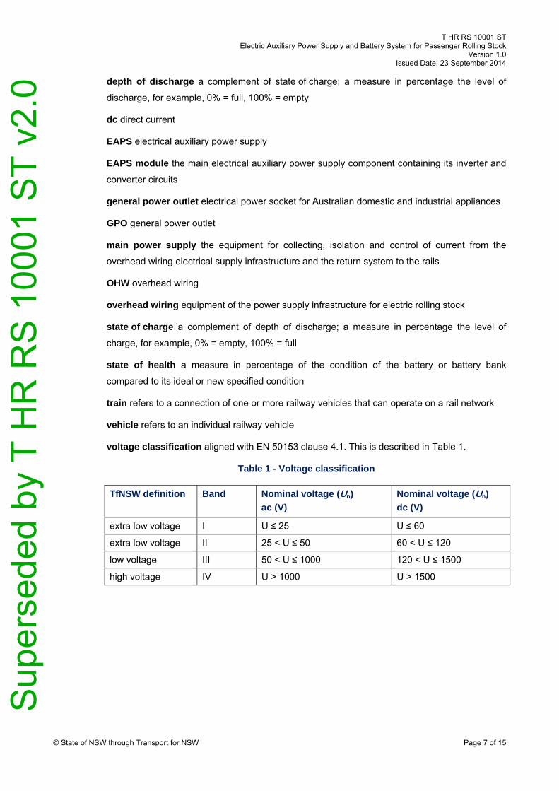
voltage classification aligned with EN 50153 clause 4.1. This is described in Table 1.
Table 1 - Voltage classification
TfNSW definition Band Nominal voltage (Un)
ac (V)
Nominal voltage (Un)
dc (V)
extra low voltage I U ≤ 25 U ≤ 60
extra low voltage II 25 < U ≤ 50 60 < U ≤ 120
low voltage III 50 < U ≤ 1000 120 < U ≤ 1500
high voltage IV U > 1000 U > 1500

Sup
erse
ded
by T
HR
RS
100
01 S
T v2
.0
T HR RS 10001 ST Electric Auxiliary Power Supply and Battery System for Passenger Rolling Stock
Version 1.0 Issued Date: 23 September 2014
© State of NSW through Transport for NSW Page 8 of 15
5. Electrical auxiliary power supply system
The EAPS system provides power to systems essential to train operation including control
circuits and the climate control system.
The electrical auxiliary power supply (EAPS) system shall comply with IEC 61287 Railway
Applications - Power converters installed on board rolling stock, IEC 60146 Semiconductor
converters - General requirements and line commutated converters, and EN 50155 Railway
Applications - Electronic Equipment Used on Rolling Stock.
The EAPS shall comply with T HR RS 00117 ST Electric Circuits and Equipment for Passenger
Rolling Stock.
The EAPS electronics enclosures and cable connectors shall be IP rated in accordance with
IEC 60529. The rating shall include the effects of exposure to jets of water from rain up to the
maximum train speed and train wash plant water jets. The rating of equipment mounted inside
hatches shall consider protection from water exposure that could occur in the event of failure of
the hatch, or sealing.
The insulated high tension negative or neutral of the EAPS dc input side shall be kept separate
from the insulated negative or neutral circuits of the EAPS output, except where these
effectively are connected via the axle earth return brush connections of the train.
For 1500 V dc operation, the EAPS system shall integrate with the whole train to comply with
ESR 0001-E Minimum Operating Standards for Rolling Stock - RSU Appendix E - Specification
for 1500 V dc Traction Supply.
The EAPS system shall be disconnected from the main power supply system in fault or failure
conditions.
It shall be possible, from the driver's cabin, to reset individual EAPS and isolate individual EAPS
modules from the main power supply.
The EAPS system shall include a safety system that lets maintenance personnel safely work on
the input side and output side of the EAPS. A lockable isolation and earthing system shall be
provided on the input and output side to provide maintenance personnel protection against any
application of power in all configurations, including any application of power from emergency
back-up feeds from other EAPS modules or from the fixed shore power supply.
5.1. EAPS protection
All EAPS extra low voltage and low voltage circuits shall be protected by individual circuit
breakers, except where fuse protection is required.
Circuit breakers shall protect associated equipment and cabling from abnormal currents.

Sup
erse
ded
by T
HR
RS
100
01 S
T v2
.0
T HR RS 10001 ST Electric Auxiliary Power Supply and Battery System for Passenger Rolling Stock
Version 1.0 Issued Date: 23 September 2014
© State of NSW through Transport for NSW Page 9 of 15
There shall be galvanic isolation between all EAPS outputs and the main power supply, except
for earth back to axle earth return connections.
In the event of a fault or abnormal condition, the EAPS shall not cause degradation to the train's
external interfaces, overhead wire, or signalling infrastructure. The equipment shall provide
protection to cover a full range of credible failures and abnormal conditions.
A loss of EAPS output that is not a result of variation of main power supply, for example, OHW
under-voltage or over-voltage, shall generate a fault indication to the driver.
The EAPS three-phase output shall be protected by over-current detection and contactors.
Inter-vehicle connectors carrying EAPS supply voltages greater than extra low voltage band II
shall be interlocked so that power is not present at the electrical contacts prior to the connectors
being connected or immediately prior to the connectors being disconnected.
The EAPS shall automatically protect itself from failure in the event of an induction motor failure
of any type.
All operational EAPS modules in a train shall automatically reset upon restoration of the
interrupted main power supply.
5.2. EAPS voltages
The control circuit voltage and lighting circuit voltage shall be extra-low voltage band II.
The frequency of the EAPS ac output shall be maintained within ± 1.0 Hz of the nominal value
under all operating conditions.
The following voltages are typical in existing TfNSW rolling stock fleet and
maintenance centres:
o 110 V dc to 120 V dc for control circuits and related auxiliary equipment – extra low
voltage band II
o 110 V dc to 120 V dc lighting and ventilation circuit – extra low voltage band II
o 400 V ac to 415 V ac, 50 Hz, for three-phase climate control modules and battery
charger systems
o 240 V ac, 50 Hz, single-phase for headlights, other auxiliary systems and general
power outlets
o 120 V dc shore fixed power supply
o 415 V ac, 50 Hz, three-phase shore fixed power supply
The neutral of the EAPS three-phase output shall be earthed and load balanced to minimise
neutral return current.
The total harmonic distortion of the EAPS ac output shall be less than 10%.
Sup
erse
ded
by T
HR
RS
100
01 S
T v2
.0
T HR RS 10001 ST Electric Auxiliary Power Supply and Battery System for Passenger Rolling Stock
Version 1.0 Issued Date: 23 September 2014
© State of NSW through Transport for NSW Page 10 of 15
5.3. Fixed shore power supply interface
A three-phase, 415 V ac, 50 Hz fixed shore power supply socket is available at existing TfNSW
passenger rolling stock maintenance centres to provide external power to the train's EAPS. The
shore supply circuit is detailed in drawing C83656 Carriage Inspection Shed 415Volt Train
Supply Main Switchboard Arrangement and Control Diagram. An interlocking system ensures
that the power from the shore supply circuit is not present at the end of the shore supply jumper
prior to connection to the vehicle.
The EAPS shall interface with the fixed shore power supply circuit detailed in drawing C83656,
which includes the interlocking circuit, operating voltage and maximum circuit breaker ratings.
The EAPS shall be interlocked with the shore supply and the main power supply interface to
prevent both systems simultaneously connecting to the train.
The shore supply connection points on the train shall not be energised from any on-board
power source including the EAPS.
The EAPS's shore supply interface shall be interlocked with the traction system to stop the
traction system from moving the train while the train is connected to the fixed shore power
supply.
5.4. EAPS redundancy
The EAPS system shall continue to operate normally through interruptions of input power from
one of the OHW current collecting devices supplying the train for up to 15 seconds.
The EAPS system shall provide a level of redundancy such that the failure of one EAPS module
in a train will not affect the operation of the train. Any other EAPS modules in the train shall be
configured so that they can provide power to the following train circuits and systems:
control circuits and related equipment
safety systems, including fire and smoke detectors
communication systems
lighting circuits
battery charger
video surveillance systems
event recorders
The EAPS system shall provide a redundant power supply to the climate control system in each
vehicle such that the loss of one EAPS module in the train will not result in the complete loss of
climate control capacity in any vehicle of the train. Refer to ASA standard 'T HR RS 08001 ST
Interior Climate Comfort for Passenger Rolling Stock'.

Sup
erse
ded
by T
HR
RS
100
01 S
T v2
.0
T HR RS 10001 ST Electric Auxiliary Power Supply and Battery System for Passenger Rolling Stock
Version 1.0 Issued Date: 23 September 2014
© State of NSW through Transport for NSW Page 11 of 15
5.5. General power outlets
General power outlets (GPOs) shall comply with the requirements of EN 50153 Railway
Applications - Rolling Stock - Protective Provisions Relating to Electrical Hazards to prevent
electric shocks.
The GPOs shall comply with AS/NZS 3112 Approval and test specification - Plugs and socket-
outlets and AS 61000.3.100 Electromagnetic compatibility (EMC) - Limits - Steady state voltage
limits in public electricity systems. The frequency of the public electricity system in Australia is
50 Hz.
GPOs for devices used while a train is in operation, for example, ovens and cash registers, and
for maintenance, for example, vacuum cleaners, shall have a maximum power rating of 2400 W.
GPOs intended for passenger use and distributed throughout passenger areas shall limit the
power to each GPO to that necessary to operate and simultaneously charge a portable personal
computer. The power-limiting system shall be self-resetting and shall remove power before any
damage can occur. Reset shall occur after the over-power condition has been removed.
GPOs intended for passenger use shall have a robust child-proof cover or a system that
ensures power is not available at the socket if an appliance plug has not been fully inserted.
6. Battery systems
A battery system provides backup power to systems critical to safety such as passenger
minimum lighting, ventilation, train control, and communication systems when the EAPS power
is not available. The battery system includes the individual batteries or energy storage devices,
and the battery management and charging system.
Battery systems shall provide backup power to all train systems to maintain the operational
safety profile of the train in the absence of EAPS output power.
The battery systems shall maintain power to the emergency lighting and ventilation systems in
all vehicles of the train in all credible emergency situations including train separation incidents.
Battery systems shall comply with T HR RS 00117 ST Electric Circuits and Equipment for
Passenger Rolling Stock and T HR RS 01701 ST Mounting and Installation of Electrical
Equipment.
All electronic components of the battery systems shall comply with EN 50155.
The battery systems electronics enclosures and cable connectors shall be IP rated in
accordance with IEC 60529. The rating shall include the effects of exposure to jets of water from
rain up to the maximum train speed and train wash plant water jets. The rating of equipment
mounted inside hatches shall consider protection from water exposure that could occur in the
event of failure of the hatch or sealing.

Sup
erse
ded
by T
HR
RS
100
01 S
T v2
.0
T HR RS 10001 ST Electric Auxiliary Power Supply and Battery System for Passenger Rolling Stock
Version 1.0 Issued Date: 23 September 2014
© State of NSW through Transport for NSW Page 12 of 15
The output of all battery banks shall be fitted with an isolation switch that is accessible from
within the vehicle.
Both negative and positive poles of all battery banks shall be protected by a fuse that is
accessible from within the vehicle. Spare fuses shall be within 1 m of the installed fuse and shall
be on a fuse holder identical to the active fuse holder.
6.1. Battery systems mechanical requirements
The battery system's batteries shall be mechanically secured to protect against dislodgement
during a vehicle derailment or roll-over.
The battery system's batteries shall be safely accessible for replacement or maintenance by
maintenance personnel.
If the batteries are accessed from within the vehicle, for example if located under the seats, the
battery compartment shall be sealed and vented to the outside of the vehicle to prevent any
battery vapours or smoke entering the vehicle. The battery compartment and its sealing system
shall withstand any battery fire intensity and duration expected from the battery type used.
6.2. Battery management and charging system
A dedicated battery management and charging system shall manage the monitoring, protection
and charging of the batteries to enable the batteries to function for their minimum operating life,
as specified in Section 6.4, and provide information to assist maintenance.
The battery management system shall protect the energy storage device or batteries from the
following, where applicable:
over-current while charging and discharging
over-voltage while charging
under-voltage while discharging
over-temperature
The battery charging system shall charge the batteries from an initial 20% state of charge to
80% state of charge within three hours under normal EAPS operation.
Automatic removal or reduction of charging current shall be used to protect the batteries.
Optimised charging cycles, shall be used to ensure the specified life of the batteries. An
example of an optimised charging cycle is 'IUIU' that uses charging characteristics consisting of
constant currents and constant voltage phases.
Passive charging systems that permanently connect the battery banks to the auxiliary dc supply
shall not be used. These charging systems provide no active overcharge protection or optimised
charging characteristics.
Sup
erse
ded
by T
HR
RS
100
01 S
T v2
.0
T HR RS 10001 ST Electric Auxiliary Power Supply and Battery System for Passenger Rolling Stock
Version 1.0 Issued Date: 23 September 2014
© State of NSW through Transport for NSW Page 13 of 15
If multiple battery banks are connected in parallel to the same auxiliary dc supply, systems shall
be used to ensure that the performance of an individual battery bank shall not have detrimental
effects on other banks during charging and discharging.
For battery banks with series-connected batteries, where applicable, the charging system shall
prevent the batteries from localised undercharging or over charging.
The battery management system shall connect to a non-proprietary commercial ethernet
network to enable communication with the train management system and condition monitoring
system. Refer TfNSW's T HR TE 41001 ST - Packet switched networks.
The battery condition monitoring system should monitor and provide the following information
where applicable:
voltage: total battery bank voltage, individual voltage of each battery in the battery bank
temperature: average temperature of the battery bank, or temperatures of individual
batteries
state of charge or depth of discharge that indicates the charge level of the battery
state of health a measurement of the overall condition of the battery
coolant flow: for air or fluid cooled batteries where applicable
current in to and out of the battery
6.3. Battery capacity and emergency load duration
The battery system at 80% state of charge shall have sufficient charge capacity to power the
train's emergency loads as specified in Table 2 and Table 3 over the full operating life of the
energy storage system.
The battery system shall have excess capacity to start the train, with the pantographs in the
lowered position, after providing emergency power for the durations specified in Table 2 and
Table 3.
If the control circuit and the lighting circuit have distinct battery banks, a method of temporarily
powering the control circuit from the lighting circuit battery banks that automatically isolates the
control battery banks shall be available. This is to start the train if the control battery banks are
depleted.
The battery system shall be able to continue to provide emergency power, beyond the specified
minimum durations in Table 2 and Table 3, up to the point of reaching the state-of-charge
necessary to start the train.

Sup
erse
ded
by T
HR
RS
100
01 S
T v2
.0
T HR RS 10001 ST Electric Auxiliary Power Supply and Battery System for Passenger Rolling Stock
Version 1.0 Issued Date: 23 September 2014
© State of NSW through Transport for NSW Page 14 of 15
Table 2 - Control circuit emergency load
System to be maintained Minimum duration
Video surveillance systems 1.5 hours after loss of OHW power
Door control and release 4 hours after loss of OHW power
Train radio equipment, PA and Intercom 4 hours after loss of OHW power
Train controls (at full load) 4 hours after loss of OHW power
Fire detection system 4 hours after loss of OHW power
Event recorder 4 hours after loss of OHW power
Table 3 - Lighting and ventilation emergency load
System to be maintained Minimum duration
Emergency ventilation 1.5 hours; refer to ASA standard 'T HR RS
08001 ST Interior Climate Comfort for
Passenger Rolling Stock'
Emergency Lighting 3 hours after loss of OHW power; refer to EN13272, at lighting luminance levels specified in 'T HR RS 12001 ST Interior and Exterior Lighting for Passenger Rolling Stock'
Marker lights on end vehicles of the train 3 days after loss of OHW power
6.4. Energy storage device requirements
The energy storage device or battery type shall have the following characteristics:
contained in a non-spill case such that no fluids can spill if the batteries are handled or
transported in any orientation
not require refilling of fluids over the operating life of the batteries
not release gas or vapour during normal operation
operational over the expected ambient temperature range specified for the train
construction that complies with the shock and vibration requirements of EN 61373 Railway
Applications - Rolling Stock Equipment - Shock and Vibration Tests, Category 1, Class B,
and sections 8 through to section 10
proven minimum operating life of five years before replacement or overhaul in rolling stock
applications with the selected battery management and charging system
made from 100% recyclable materials at end of life

Sup
erse
ded
by T
HR
RS
100
01 S
T v2
.0
T HR RS 10001 ST Electric Auxiliary Power Supply and Battery System for Passenger Rolling Stock
Version 1.0 Issued Date: 23 September 2014
© State of NSW through Transport for NSW Page 15 of 15
The contractor shall provide a whole of life cost report to the TfNSW contract administrator that
details the cost of replacement, corrective maintenance, preventative maintenance, and
operating cost of the battery type and battery management and charging system. The whole of
life cost report shall be in accordance with T MU AM 01001 ST Life Cycle Costing.