electr/cal and computer engineering
TRANSCRIPT

_!.!.!(MSA-C»- 182886) ERROR COMTEOL -TECHNIQUESFOB|'SflTEllITE AMD ' S.PACI-COBBOKICATIOHS(Bot're Danse UEiv".) , 140 p CSCL 17B
H88-23922
UnclasG3/32 014.2.709
Departmcnt-o/
ELECTR/CAL AND COMPUTER ENGINEERING
UNIVERS/iy OF NOTRE DAME, NOTRE DAME, INDIANA!

Annual Status Report
Error Control Techniques for Satelliteand Space Communications
NASA Grant NAG5-557June 1988
Daniel J. Costello, Jr.Department of Electrical and Computer Engineering
University of Notre DameNotre Dame, IN 46556

Summary of Progress
During the period December 1, 1987 - May 31, 1988, progress was made in the followingareas:
1) Construction of Multi-Dimensional Bandwidth Efficient Trellis Codes with MPSK Modu-lation.
Multi-dimensional trellis coded modulation schemes using either 8PSK or 16PSK modulationappear to have great promise for achieving high data dates on satellite communication channels.Work by Ungerboeck [1,2], Hemmati and Fang [3], Fujino et.al. [4], and others has demonstratedthat 2-dimensional (one signal/time unit) rate 2/3 (3/4) trellis coded SPSK (16PSK) modulationis capable of achievilng data rates in excess of 100 Mbps on satellite channels. The promise ofeven higher rates is possible with multi- dimensional trellis coded schemes. For example, with2L-dimensional schemes, L > 2, where L signals are transmitted per time unit, speeds of upto L times those achievable with 2-dimensional schemes may be possible. This depends on fastcomputational techniques being developed to compute the metric of L successive signals on atrellis branch in the Viterbi algorithm. For moderate values of L (L < 4), this seems feasibleusing table look-up methods.
We have conducted an extensive search for good multi- dimensional trellis codes with 2 <L < 4 for both SPSK and 16PSK modulation. These codes achieve coding gains (over uncodedtransmission at the same rate) of up to 5.5 dB. In addition, many of the codes are fully transparentto discrete phase rotations of the signal set (45° transparency for SPSK and 22.5° transparencyfor 16PSK) through the use of differential encoding. A paper summarizing our work in thisarea has been accepted for publication by. the IEEE Transactions on Information Theory and isincluded as Appendix A of this report [5]. "
It is recommended that NASA proceed with the development of one of these codes fortheir high speed satellite transmission schemes of the future. A good choice would be the six-dimensional (L = 3), 16-state, rate 7/8, SPSK code listed in Table 9(b) of the paper. This codehas a 3.57 dB coding gain compared to uncoded modulation of the same rate. and is transparentto 90° phase rotations of the signal'set. With proper decoder implementation, this code wouldbe capable of operating at three times (L = 3) the speed of a comparable two-dimensional code.In terms of current technology, this offers the possibility of reliable transmission at speeds inexcess of 300 Mbps.
2) Performance Analysis of Bandwidth Efficient Trellis Coded Modulation SchemesMost of the bandwidth efficient trellis code constructions which have been published in the
literature measure performance with a parameter d^ree, the minimum free squared Euclideandistance of the code. This is determined by the two codewords (signal sequences) which are closesttogether in terms of squared Euclidean distance. This parameter determines the asymptotic (highsignal-to-noise ratio) coding gain 7 of the system through the formula
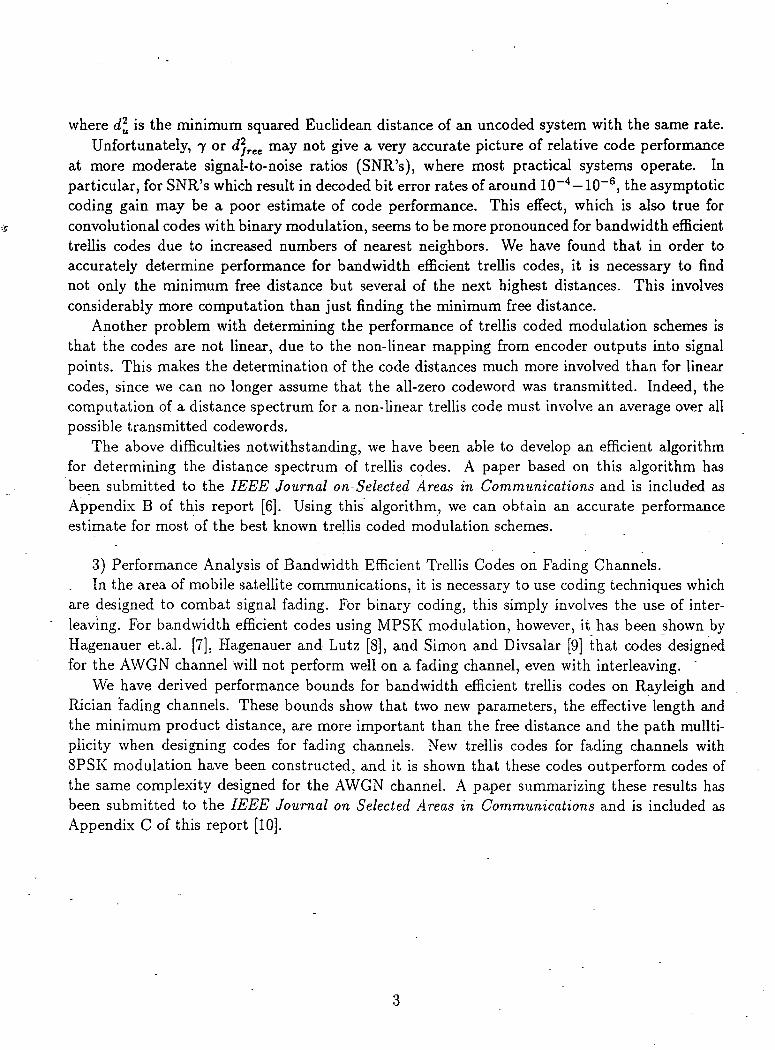
where d^ is the minimum squared Euclidean distance of an uncoded system with the same rate.Unfortunately, 7 or d^ree may not give a very accurate picture of relative code performance
at more moderate signal-to-noise ratios (SNR's), where most practical systems operate. Inparticular, for SNR's which result in decoded bit error rates of around 10~4 —10~6, the asymptoticcoding gain may be a poor estimate of code performance. This effect, which is also true forconvolutional codes with binary modulation, seems to be more pronounced for bandwidth efficienttrellis codes due to increased numbers of nearest neighbors. We have found that in order toaccurately determine performance for bandwidth efficient trellis codes, it is necessary to findnot only the minimum free distance but several of the next highest distances. This involvesconsiderably more computation than just finding the minimum free distance.
Another problem with determining the performance of trellis coded modulation schemes isthat the codes are not linear, due to the non-linear mapping from encoder outputs into signalpoints. This makes the determination of the code distances much more involved than for linearcodes, since we can no longer assume that the all-zero codeword was transmitted. Indeed, thecomputation of a distance spectrum for a non-linear trellis code must involve an average over allpossible transmitted codewords.
The above difficulties notwithstanding, we have been able to develop an efficient algorithmfor determining the distance spectrum of trellis codes. A paper based on this algorithm hasbeen submitted to the IEEE Journal on-Selected Areas in Communications and is included asAppendix B of this report [6]. Using this algorithm, we can obtain an accurate performanceestimate for most of the best known trellis coded modulation schemes.
3) Performance Analysis of Bandwidth Efficient Trellis Codes on Fading Channels.In the area of mobile satellite communications, it is necessary to use coding techniques which
are designed to combat signal fading. For binary coding, this simply involves the use of inter-leaving. For bandwidth efficient codes using MPSK modulation, however, it has been shown byHagenauer et.al. [7], Hagenauer and Lutz [8], and Simon and Divsalar [9] that codes designedfor the AWGN channel will not perform well on a fading channel, even with interleaving.
We have derived performance bounds for bandwidth efficient trellis codes on Rayleigh andRician fading channels. These bounds show that two new parameters, the effective length andthe minimum product distance, are more important than the free distance and the path mullti-plicity when designing codes for fading channels. New trellis codes for fading channels withSPSK modulation have been constructed, and it is shown that these codes outperform codes ofthe same complexity designed for the AWGN channel. A paper summarizing these results hasbeen submitted to the IEEE Journal on Selected Areas in Communications and is included asAppendix C of this report [10].

References
[1] G. Ungerboeck, "Channel Coding with Multilevel Phase Signals," IEEE Transactions onInformation Theory, IT-28, pp. 55-67, Jan. 1982.
[2] G. Ungerboeck, "Trellis Coded Modulation with Redundant Signal Sets - Part I: Introduc-tion and Part II: State of the Art," IEEE Communications Magazine, Vol. 25, no. 2, pp.5-21, Feb. 1987.
[3] F. Hemmati and R. J. F. Fang, "Low Complexity Coding Methods for High Data RateChannels," Comsat Technical Review, Vol. 16, pp. 425-447, Fall 1986.
[4] T. Fujino et.al., "A 120 Mbits/s Coded 8PSK Modem with Soft-Decision Viterbi Decoder,"IEEE International Conference on Communications Conference Record, pp. 1774-1780,Toronto, Canada, June 1986.
[5] Robert H. Deng, Steven S. Pietrobon, Alain Lafanechere, Gottfried Ungerboeck, and DanielJ. Costello, Jr., "Multi-Dimensional Trellis Coded Phase Modulation," IEEE Transactionson Information Theory, to appear.
[6] Marc Rouanne and Daniel J. Costello, Jr., "An Algorithm for Computing the Distance Spec-trum of Trellis Codes," submitted to IEEE Journal on Selected Areas in Communications.
[7] J. Hagenauer et.al., "The Maritime Satellite Communication Channel," IEEE Journal onSelected Areas in Communications, Vol. SAC-5, No. 4, pp. 701-713, May 1987.
[8] J. Hagenauer and E. Lutz, "Forward Error Correction Coding for Fading Compensationin Mobile Satellite Channels," IEEE Journal on Selected Areas in Communications, Vol.SAC-5, No. 2, pp. 215-225, February 1987. . "
[9] M. K. Simon and D. Divsalar, "Trellis Coded Modulation for 4800-9600 bits/s TransmissionOver a Fading Mobile Satellite Channel," IEEE Journal on Selected Areas in Communica-tions, Vol. SAC-5, No. 2, pp. 162-177, February 1987.
[10] Christian Schlegel and Daniel J. Costello, Jr., "Bandwidth Efficient Coding for FadingChannels," submitted to IEEE Journal on Selected Areas in Communications.

Appendix A
Multi-Dimensional Trellis CodedPhase Modulation

Multi-Dimensional Trellis Coded PhaseModulation*
Robert H. Deng,* Steven S. Pietrobon,*Alain LaFanechere,§ Gottfried Ungerboeck,^
and Daniel J. Costello, Jr."
May 12, 1988
Abstract
In this paper, multi-dimensional trellis coded MPSK modulation is inves-tigated. A 2L-dimensional (L > 2) MPSK signal set is obtained by formingthe Cartesian product of L 2-dimensional MPSK signal sets. A systematicapproach to partitioning multi-D signal sets is used which is based on blockcoding. An encoder system design approach is developed which incorporates,the design of a differential precoder, a systematic convolutional encoder, and asignal set mapper. Multi-dimensional trellis coded 8PSK and 16PSK modula-tion schemes are found, for a variety of rates and decoder complexities, manyof which are fully transparent to discrete phase rotations of the signal set.Asymptotic coding gains up to 5.5 dB have been found for these codes.
"This work was supported by NASA Grant NAG5-557 and OTC(Australia) R&D ProgrammeNo. 4.
^Institute of Systems Science, National University of Singapore, Kent Ridge, Singapore 0511.Formerly with the Dept. of Electrical and Computer Engineering, University of Notre Dame.
*Dept. of Electrical and Computer Engineering, University, of Notre Dame, Notre Dame, IN,46556, U.S.A. and School of Electronic Engineering, South Australian Institute of Technology, TheLevels, P.O. Box 1, Ingle Farm S.A. 5098, Australia.
5Enertec Schlumberger, 1 Rue Nieuport, 78141 Velizy, France. Formerly with the Dept. ofElectrical and Computer Engineering, Illinois Institute of Technology, Chicago, IL, 60616, U.S.A.
^IBM Zurich Research Laboratory, Saumerstrasse 4, CH-8803 Riischlikon, Switzerland."Dept. of Electrical and Computer Engineering, University of Notre Dame, Notre Damp. TN,
46556..U.S.A.
1

1 Introduction
Since the publication of the paper by Ungerboeck [1], Trellis Coded Modu-lation (TCM) has become a very active research area [2-9]. The basic idea ofTCM is that by trellis coding onto an expanded signal set (relative to that neededfor uncoded transmission), both power and bandwidth efficient communicationcan be achieved.
TCM can be classified into two basic types, the lattice type (e.g., M-PAM,M-QASK) and the constant-envelope type (e.g., MPSK). The latter has a lowerpower efficiency compared with the former but is more suitable for band-limitedsatellite channels containing nonlinear amplifiers such as traveling wave tubes(TWT). Taylor and Chan [10] and Wilson et. al. [11] have studied the performanceof rate 2/3 TC-8PSK and rate 3/4 TC-16PSK, respectively, for various channelbandwidths and TWT operating points. Their results showed that TC-MPSKmodulation schemes are quite robust under typical channel conditions.
In any TCM design, partitioning of the signal set into subsets with increasingintra-subset minimum distances plays a central rule. It defines the signal mappingused by the modulator and provides a tight bound on the minimum free squaredEuclidean distance (FSED) between code sequences,.allowing an efficient searchfor optimum codes. For lattice-type TCM, Calderbank and Sloane [8] have madethe important observation that partitioning the signal set into subsets correspondsto partitioning a lattice into a sublattice and its cosets. Forney [9] has developeda method, called the "squaring construction", of partitioning higher dimensionallattices from a lower dimensional lattice by using a coset code.
In this paper, we investigate a class of multi-dimensional (multi-D) trelliscoded MPSK (TC-MPSK) modulation schemes. The 2X-dimensional-(2L-D)MPSK signal set is generated by simply repeating an MPSK signal set L times(L > 2). Therefore, the 2L—D MPSK signal set is the Cartesian product of L2-D MPSK signal sets. Multi-D MPSK signal sets provide us with a number ofadvantages that can't be found in a 2-D signal set: (i) flexibility in achievinghigher effective information rates, (ii) better coding gains, (iii) easy constructionof some codes which are invariant to phase rotations, and (iv) due to their byteoriented nature, suitability for use as inner codes in a concatenated coding system[12].
In Section 3, we introduce a block coding technique for partitioning a multi-D MPSK signal set. We will show that partitioning a 2L-D MPSK signal set
is isomorphic to partitioning an L x Iog2 M binary matrix space. This sectionis mathematically rigourous. Thus, a brief description of the major ideas andconcepts is given in Section 2 by way of an example. Section 4 describes howthe encoder system, comprising a differential precoder, a systematic convolutionalencoder, and a multi-D signal set mapper, is constructed from the best codes foundin a systematic code search. The signal sets are constructed such that the codesare transparent to integer multiples of 360°IM rotations of the MPSK signal set.The systematic code search is based on maximizing the FSED (and thus theasymptotic coding gain) as well as minimizing the number of nearest neighborsfor each phase transparency. 4-D, 6-D, and 8-D TC-8PSK codes and 4-D and6-D TC-16PSK codes are listed with coding gains up to 5.5 dB compared to anuncoded system. In addition, these codes require no bandwidth expansion.

2 A Block Coding View of Set Partitioning
In this section we give a description of how partitioning a 2-D 8PSK signalset can be viewed in terms of block coding. This relatively simple example is usedto describe the concepts used to partition multi-D MPSK signal sets in Section 3.
A naturally mapped 8PSK signal set is illustrated in Figure 1. The reason forusing natural mapping is that the three mapped bits can be used directly to indicatethe minimum squared subset distance (MSSD). If each of the three bits y°, y1,and y2 is allowed to be 0 or 1, i.e., y-7 6 {0,1} for j = 0,1 and 2, then there willbe some combinations (e.g., 000 and 111) where the minimum possible distancebetween two points is achieved. In this case the MSSD will be 2 — \/2 ~ 0.586 ifthe average energy of the signal set is taken to be one. However, if we set y° = 0and let yj' e {0,1} for j = 1 and 2, then the MSSD of the resulting subset will be2. One can view this as y° belonging to a simple length one block code that hasonly one code word, i.e., 0. We say that the Hamming distance of this block codeis infinity, since that is the distance required to reach all the other (non-existent)codewords. This length one block code concept can also be applied to the othertwo mapping bits y1 and y2. These can be thought of as uncoded cases wherethere are two code words, 0 and 1, and where the Hamming distance is one.
One may ask "What is the use of this block code description, when wehave the much simpler description given by Ungerboeck [1]?". As will be seen,although this is a complicated description for the simple 2-D case, for higherdimensions this description yields a powerful and easy method of partitioning amulti-D signal set.
Now that we have described the signal set in terms of block codes, albeit theyare trivial, we can use the equation for MSSD given by Sayegh [13] from workoriginally done by Cusack [14]. Before we give this equation, some notation isneeded. Let d? be the Hamming distance for the block codes corresponding tothe bits y-7 for j = 0, 1, and 2. Also let the MSSD that corresponds to settingy° , . . . , y-7"1 to 0 be 8? for j =0, 1, and 2. We have already determined thatSQ = 0.586 and 52 = 2. For the remaining MSSD, it can easily be shown that60 = 4. The 8PSK signal set can be seen to have three levels of partitioning.A parameter p is used to designate the partitioning level. The initial level ofpartitioning is denoted by p — 0. This corresponds to all eight 8PSK signalpoints. The first level of partitioning (p = 1), corresponds to a subset of four

points. This can be continued until we reach the final level with p = 3 and onlya single point. From [16], the MSSD at partition level p is
Due to the symmetry of the 8PSK signal set, the lower bound is an equality. Forp = 0, d$ = df = dfi = 1, and thus A2, = 0.586. For p = 1, dj = oo, andthus A2 = 2. Similarly A2 = 4 and A2 = oo. Note that in this case A2 = 6*.However, for multi-D schemes, more complicated block codes are used where <$can have values of 2, 3, or more. Thus, in some cases, Ap ^ 6*.
Note that the above example considers only a single branch of a partition.Going back to our original description, we can also set y° = 1, y1 (E {0,1}, andy2 6 {0,1}. Due to the symmetry of the 8PSK signal set the subset selected alsohas an MSSD of <52. A block code view of this subset is that it is the coset of thesubset selected by y° =0. The reason is that we can take the coset representative(which is 1) of the coset {1} corresponding to the simple block code {0} andadd it modulo-2 to y° = 0, which selects the first subset, to obtain y° = 1, whichselects the other subset. This coset representative is a codeword at the previouspartition level, but is not a codeword at the current partition level. That is, thecoset representative (1) belongs to the code {0,1} at p = 0 but not to the code{0} at p = 1. In a similar manner, codes corresponding to y1 and y2 can bepartitioned using coset representatives until all 8 signal points belong to subsetscontaining only a single point. This is an important concept, since a multi-Dsignal set partition can be directly described by its cosets, right down to a singlepoint, a s will b e shown i n Section 3 . " . . - - .
To obtain a multi-D signal set, one can view yj as containing more than onebit. In fact, yj becomes a vector vj that corresponds to the jth bits of two or moresignal sets. This vector v-' contains only one bit for a 2-D signal set, and thus theblock codes have length one. However, for a 2L-D signal set, there are L bits inthe vector W, which will belong either to a block code of length L or to one of itscosets, depending on which partition path is chosen. If there are M = 21 signalsin each 2-D signal set, then there will be I = Iog2 M sets of these codewords.

3 Multi-D MPSK Signal Set Partitioning
We begin this section with a discussion of partitioning a binary matrix space.We then show that partitioning a 2L-D MPSK signal space is isomorphic topartitioning an / = Iog2 M x L binary matrix space.
3.1 Partitioning a binary matrix space
Let Cm, with m = 0,1,..., L, be a sequence of (L, L-m) binary linear blockcodes with generator matrices Gm and Hamming distances dm such that CL CCL-I C - - - C i C C0. Denote the L-D binary vector space by \i = {Q,l}L.Then C0 = Vif and C 0 /Ci / - - - /C £ _i /C £ forms a 2/2/.J2/2 (L times)-waybinary vector space partition chain. The 2m—way binary vector space partition,Co/Cm, divides C0 into Cm and its 2m -1 cosets, Cm(l), Cm(2),. . . , Cm(2m -1). Let tm(u) be the coset representative of Cm(u), where u is the integerrepresentation of the binary vector u = [u"1"1,..., u1, u°], i.e., u = 2m~1um~1 +
h 2V + 2°u°. Then Cm(tt) and Cm are related by
Cm(ti) = Cmetm(«). . (1)
where © indicates modulo-2 addition.
The coset representative of Cm is the L—D all-zero vector and is denoted by
tm(0). Let rm — tm(2m-1) be the coset representative such that
Zm 6 m_i, Tm
We call rm a principle coset representative, since these are the particular cosetrepresentatives which can be used to fully describe all the cosets. The mappingthat we assume is that the first m - 1 bits of u are all 0 so that um~ l = 0selects Cm and um~ l = 1 selects the coset Cm(2m~1). Note that rm can be anycodeword in Cm(2m~1). Thus an expression for any coset representative is
m-l
tm(tO = um~ lrm @ • • • © u lr2 © u°Ll = 0 u*Ti+l. (2). j=o

Example 3.1:For the 2-D binary vector space V2={0,1}2, we may form the following blockcodes:
C0: (2,2) code, Go =
Ci: (2,1) code, GI = [1 1], <*i = 2;
C2 : (2,0) code, G2 = [0 0], J2 = oo.
Note that C2 C Ci C C0. The 2/2-way partition chain C0/Ci/C2, along withthe 2-way partitions Co/Ci and Ci/C2 and the 4-way partition C0/C2, is shownin Figure 2. The principle coset representatives are ra = [0 1]T and r2 = [1 1]T.
We now describe how I of the above block codes can be used to describe anL x / binary matrix space. Let Cm. be an (L, L — m,-) linear block code that is asubspace of VL, mt- = 0,1,..., L. Define Q,p = ft(Cm/_,,..., Cmi, Cmo), where
p = X)i=o m» ^s tne ^eve^ °f partitioning, as the set of all L x I binary matrices:
4J = [ J-i V1V°1 =../-I
}L-\ JL-l
(3)
where v1 e Cm;, i = 0, 1, . . . , I — 1, and each v' is an L— dimensional columnvector. Op is a subspace of fi° = Q(V^, . . . , V^, V^) and is a group under binarymodulo-2 matrix addition. £lp is called the principle subset of fi°. fi°/fip is a2P way binary matrix space partition which divides fi° into £lp and its 2P — 1cosets, ftp(z) = ^(C^.^^), . . . ,Cmo(z)), 1 < z < 2P-1 where z is the integerrepresentation of the binary vector z = [zp~l, . . . , z l ,zQ\ . Cm,.(z) is either Cm, ora coset of Cmi, depending on the partition level p and the particular value of z.The coset representative of fip(z) is given by o;p(z) = w(tm /_j(z), . . . ,tmo(z)),where tmi(z) is the coset representative of Cm.(z}. The principle subset and itscosets are related by
0, 1, .
) = np©o;p(z). (4)
is said to be a subspace of ftp/ if and only if p > p' and Cmi C Cmj , i =
.,/- 1. In this case fip partitions ftp' and forms a 2P~P' way binary

matrix space partition, and S70/fip'/fip forms a 2p//2p~p'-way binary matrixspace partition chain.
Example 3.2:Let C0 = V2, Ci, and C2 be the (2,2), (2,1), and (2,0) binary block codesdefined in Example 3.1. Table 1 illustrates a partition chain for 7 = 3. Thusft0 is a 2 x 3 binary matrix space, and ft^ft2,... ,ft6 are all principle subsetsof ft0. Moreover, ft0 D ft1 D ft2 D ft3 D ft4 D ft5 D ft6. Therefore,ftVftVft2/^3/^4/^5/^6 forms a 2/2/2/2/2/2-way binary matrix space partitionchain. The first three levels of this partition chain are shown schematically inFigure 3. When Cm<(z), z > 0, is the same as Cm,, then Cmi is given. Thedetermination of the coset representatives can be found using a technique similarto that described in (2) at the beginning of this subsection, that is, by the use ofprinciple coset representatives. However, it is not always necessary to use linearor modulo-2 arithmetic, as will be shown in Section 4, where non-linear arithmeticis used. This allows the binary matrix space to have special properties that willbe described later. The coset representatives for Figure 3 can be determinedeasily from the partition chains. For example, the coset representatives of ft3
are given by
t^co^-e* 0 -* 1 )? ,
where m0 = 2, mi = 1, m2 = 0 and z° • z1 indicates the logical AND of z°and z1. Note the differences between the above equations and (2). For tm,(z) itcan be seen that z2 selects TJ (along with a non-linear term), since we are nowpartitioning CQ for i = 1. It should be noted that there are many other partitionchains of the 2x3 binary matrix space.
3.2 Partitioning a 2L-D MPSK signal spaceThe 2-D MPSK signal set, denoted by Si(M), is the set of complex MA
roots of unity, that is, 52(M) = {e(*IM)e^(z*IM)9^_ ^((2M-i)*/M)e^ where

9 = ^/^l and M = 2J for any positive integer I. S2(M) is a group under com-plex multiplication. For simplicity, we write 5*2(M) — (y : y = 0,1,..., M— 1},where y is the integer representation of the binary number y = [y7"1,..., y1, y0].This binary or natural mapping of the signal points in 52(M) is assumed through-out the paper. The 2L-D, £ > 2, MPSK signal set is defined as the Cartesianproduct of L 2-D MPSK signal sets, that is,
S2i(M) = S2(M) x S2(M) x • • • x S2(M) (L times). (5)
Therefore, the 2L-D MPSK signal set is generated simply by repeating an MPSKsignal set L times.
Letting y/, / = 0,1,..., L - I be a sequence of L signal points inwe now form an L x I matrix
Y =
yoy}
y0°y?
y(6)
where the rwo vectors y/ represent points in 2-D space and Y represents a pointin 2L-D space.'
Using the notation introduced in the last subsection, the L x I matrix subspacefip consists of the L x / matrices u defined in (3). Using (6) and (3), a 21,-DMPSK signal subset, denoted by Pp - P(Cm/_,,... ,Cmo) is obtained from ftp
by the following mapping: . -
Y=si, (7)
i.e., y] = v], i = 0,1,...,/- 1 and / = 0,1,..., L - 1. Since the matrix wcontains L rows, it is mapped into a 2L—D signal point in 52i(M), with the firstrow corresponding to the first two dimensions and the last row corresponding tothe last two dimensions of the signal point, or equivalently, w is the binary repre-sentation of a signal point in Soi(M). Moreover, since Q,p contains 2IL~P Lx Imatrices, the signal subset Pp contains 2IL~P 2L-D signal points. Therefore , fip

and Pp are isomorphic. The minimum squared Euclidean subset distance (MSSDor Aj) of PP is given by [13]
Aj > min^J,^,., , . . . , 6ldmi , tfJ^U), (8a)
where
/2I+17T\£? = 2-2cos(^-J, i = 0,l,. ..,/-!, (8b)
is the MSSD of S2(M/2') (recall that M = 27) and dm,. is the minimum Hammingdistance of Cm., i = 0, 1, ...,/- 1. Due to the symmetry of MPSK signal sets,the inequality in (8a) becomes an equality, and thus for 8PSK and 16PSK (/ =3 and 4, respectively), (8a) and (8b) lead to
, 2dmi , 0.5858Jmo), (9a)
and
Aj =min(4dm3,2<ima,0.5858drai, 0.1522^), (9b)
respectively. The mapping in (7) is used in [13-16] to construct block codes insignal space.
The signal set corresponding to ftp is just the 2L-D MPSK signal set52i(M). It is easy to see that Pp is a subset of 52i(M), provided that fip is asubspace of Q°. Pp is called the principle subset of Soi(M) and is a group undercomplex multiplication. Hence, 52i(M)/Pp is a 2p-way partition which divides52i(M) into Pp and its 2P - 1 cosets Pp(z) = P(Cm/_1(z), . . . ,Cmo(2)), 1 <z < 2P - 1. The signal cosets can be obtained from the corresponding matrixcosets through the mapping in (7).
Example 3.3:Using the mapping in (7), a 4-D 8PSK signal set partition chain, based on the2x3 binary matrix space partition chain of Example 3.2, is shown in Table 2.
10 -

The first three levels of the partition chain are shown schematically in Figure 4.The MSSD's are obtained from (9a). The partition chain in Figure 4 has specialproperties in relation to phase rotations which can be found from the principlecoset representatives. The derivation of these properties will be explained inSection 4.
Example 3.4:This example illustrates how to partition the 6-D 8PSK signal set. In the 3-Dbinary vector space C0 = V3 = {0,1 }3, there exists a (3,2) code and a (3,1)code with Hamming distances 2 and 3, respectively. However, the (3,1) code isnot a subcode of the (3,2) code. Consequently, three different 2/2/2-way binarymatrix space partition chains are possible: Co/Cj/C^/Cs, Co/C^/C^/Cs, andC0/C|/C^/C3, where C3 is the (3,0) code and
C}: (3,2
CJ: (3,1) code, Gj = [0 1 1], 4 = 2,
C': (3,2)code,G? = [j ° ? ] , « * ? = 1,
" C j : (3,1) code, Gl = [l 1 l ] ,d | = 3.
Note that C3 C C\ C C\ C C0, C3 C C' C C\ C C0, and C3 C C\ C C? C C0.A. variety of 6-D 8PSK signal set partition chains can be constructed based onthese three 3x3 binary matrix space partition chains. Two 6-D 8PSK signal setpartition chains obtained by the mapping in (7) are given in Tables 3(a) and 3(b).
An 8-D 8PSK signal set partition chain is given in Table 4. Before leavingthis section, we give one more example to show how to partition multi-D 16PSKsignal sets.
Example 3.5:In this example, we partition the 4-D 16PSK signal set. Let Co, Ci, and C2
be the (2,2), (2,1) and (2,0) binary block codes defined in Example 3.1. For/ = Iog2 16 = 4, Table 5 illustrates the partition chain that is used. Then 17°is a 2 x 4 binary matrix space, and Q1 ,^2 , . . . ,^8 are all principle subsets
11

of ft0. Moreover, (2° D ft1 D •-• D fi8. Therefore ft0/&/•••/& forms a2/2/2/2/2/2/2/2-way binary matrix space partition chain. The first three levels ofthe partition chain are shown in Figure 5. The MSSD's are found from (9b).
Three 6-D 16PSK signal set partition chains are listed in Tables 6(a)-6(c),respectively. The corresponding binary matrix space partition chains can be readfrom these tables.
From the above discussion, we observe that various partitions can be con-structed for a given multi-D MPSK signal set, and this establishes the basis forconstructing good codes. It should be pointed out that Forney's [9] squaring con-struction and 3-construction can also be applied to partitioning multi-D MPSKsignal sets. The resulting partitions, however, may be inferior to the partitionsintroduced above. For example, in partitioning the 8-D 8PSK signal set usingthe squaring construction (or 4-construction), A^ =2 instead of 2.343 as shownin Table 4.
12

4 Multi-D TC-MPSK DesignThis section describes how convolutional codes are constructed for the 2L—D
MPSK signal sets described previously. We first describe how to construct signalsets which have good phase rotation properties. Following this, the method usedto find good convolutional codes based on parity check equations is presented.
4.1 Construction of signal setsIn the previous section, a signal set was described in terms of the principle
subset ft? and its cosets ftp(z), 0 < z < 2P -1. In Section 3.1, it was shown thatfor / = 1, cosets can be constructed by using the principle coset representativesrm. For / > 1 we can use a similar technique, where the principle cosetrepresentative rp at partition level p — m,- is given by
TP = up(2p~l).
If m, retains the same value going from partition level p — 1 to p, thentmi(2
p-1) equals the all zero vector 0 = [0...0]T. This can be seen in Figures 3 to5j where at partition level p and z = 2P~1, only those m;.'s that increase from p—1to p have any effect on the coset. There is no principle coset representative forp = 0, since the binary matrix space fi° has no cosets. Also note that TP e &p~l
and T? £ fip.
Example 4.1For the partition chain in Table 2, the principle coset representatives rp for the4-D 8PSK signal space are
r2 = [to(2),to(2),t2(2)] = [0,0,r2],
Z3 = [to(4),t1(4),t2(4)] = [0,rI,0],
r4 = [to(8),t2(S),t2(8)] = [0,r2,0],
T5 = [t1(16),t2(16),t2(16)] = [li.O.O],T6 = [t2(32),t2(32),t2(32)] = [r2,0,0],
where TJ = [0 1]T, r2 = [I 1]T, and 0 is the all zero vector [0 0]T.
13

As in (2), we can find the coset representatives at any partition level by themodulo-2 addition of the respective principle coset representatives, i.e.,
P-I+1; 0 < z < 2P - (10)
,=o
An alternative and more useful way of forming the cosets is as follows. AnL x 1 M—ary vector space u; can be formed such that
7-1
(U)i=o
where modulo-M arithmetic is used and I is the number of non-zero values ofmi at partition level p. Then the principle coset representatives can be expressedin integer form as
r* = (12)
where modulo-M = 21 arithmetic is used. Note that rp is an L x 1 vector andthat its elements belong to the set 0,1,..., M — 1. The coset representatives atpartition level p are then
P-I; 0 < z < 2P - 1, (13)
3=0
where modulo-M arithmetic is used.
Example 4.2:For the principle coset representatives found in Example 4.1, the principle cosetrepresentatives in integer from for 4-D 8PSK are found from (12) as
0T4 =
22
14

To find the coset representative (in integer form) at partiton level p = 3 andfor z = 3, we see from Table 2 that 1 = 2, and hence from (13)
u,3(3) = zV + zV + zV = 0 +1 +1I •!• I
where modulo-4 arithmetic is used.
In a practical implementation of an encoder, a single point in multi-D space,given a value of z, can be found by partitioning down to level p = IL. At thispartition level the coset representatives themselves are the actual points in signalspace. We call tins full partitioning. Let y(z) represent each 2L—D MPSK pointY in integer form, i.e,
yo
l'VL-1 J
7-1
, where yt = ^2'y}, / = 0,1,...,L-l.i=0
(14)
The variable z is used in y(z) since each point in Y can now be described interms of z. Thus, with full partitioning, we obtain (for p — IL)
IL-lILy(z) = U ( Z ) = 0 < 2 < IL - 1, (15)
;=0
where addition is modulo-M.Equation (15) can now be used to describe a signal point in 2L-D space with
MPSK modulation. The number of bits z^ used to describe a signal point is IL.If the least significant bit (Isb) is used for coding, we can form a rate (IL — l)/ILcode. Other rates can also be formed by letting the q Isb's of the mapping be setto 0. We do this to insure that the MSSD's are as large as possible, and thus thebest codes can be found. Therefore we let
IL-l
- 0 < z < -1, 0 < q < L - l , (16)3=1
15

where yq(z) represents a point z in 2L-D MPSK signal space such that the firstq bits of (15) are 0 and addition is modulo-M. Now z = [z IL~q~ l,...,z l,z°],where the Isb of z is always the coding bit. This insures that the parity checkequations can always be expressed in terms of z without depending on thetype and partition level of the signal set used. From (16), codes of rates(IL — q ~ l)/(IL — q) can be formed. An upper limit of q = L — 1 is setbecause for q > L the signal set is partitioned such that dmo = oo, i.e., anM/2> - PSK, j > 1, signal set is being used (one exception is the 8-D 8PSKsignal set (Table 4) where dmo = oo for q > L +1). The MSSD's range from Ajto A|£ and the uncoded minimum squared Euclidean distance (SED) is ,
Example 4.3:We can form a rate 4/5 code with 4-D 8PSK modulation (q = 1, L = 2, 7 = 3).Then
+ Z1 0+ zv
where addition is modulo-S.The uncoded minimum SED isthe same as uncoded QPSK.
= 2.0, which is
4.2 Effect of a 360°/M phase rotation on a Multi-D MPSK signal set
The reason for constructing the signal set as in (16) is that there are at most /bits, in z affected by a signal set rotation of # = 360° /M. For 8PSK and 16PSK,this corresponds to rotations of 45° and 22.5°, respectively. Initially, we considerall possible mapped bits, and thus q = 0.
Consider that a 2-D MPSK signal set has been rotated by $. Since weare using natural mapping, the integer representation of the rotated signal pointis yT = y + I, where y is the integer representation of the signal point beforerotation and modulo-M addition is used. If binary notation is used, then
yr° = y ° © l , (17a)
(rfc)
16

If there are / = Iog2 M bits in a signal set, then all I bits are affected by aphase rotation of \&.
We now consider the first partition of a multi-D MPSK signal set z° is usedto select one of two partitions, P(C0,... ,C0,Ci) or P(C0,...,C0,Ci(l)). Weknow from (17a) that the Isb's are inverted by a $ phase rotation. Then, if all thecode words in Ci remain code words in Ci when inverted, then z° will remainthe same after a phase rotation. That is, if GI = Ci, then zj? = z°. However, ifCi = Ci(l), then z° = z° © 1, as can be seen from the set partition. A simpleway to tell if a block code has the property that Cmj = Cmi, or if Cm, equals oneof its cosets, is to examine its coset representative at that partition level. AssumeTm. = [l...l]T = 1. Since rm. € Cmi_i, then Cm;_i = Cm,._i follows fromcode linearity (the inverse of rm. = 1 is the all zero vector 0). However, we alsohave rm. g Cm., and thus the inverse of 0 and all the other vectors in Cm; forma coset of Cmi (again for linear codes). Thus, if rm. ^ 1 at partition level p thenzp-1 = z?-1; otherwise, zp~l ^ zp~l.
For Cmo, we can always say that if rmo = 1 at partition level p, then zp~l =zp~l © 1; otherwise, z?"1 = zp~l, since the additions for yf, I = 0,1,. . . , L - 1,are modulo-2 using either (10) or (16) to map a signal point. However, for i > 1,.(10) gives signal sets which have IL — I—l bits affected by a phase rotation. Thisis because an inverted zp which affects Cmo will cause some signal points to rotatein different directions. However, using the mapping in (16), all the signal pointswill rotate in the same direction, since modulo-M arithmetic is used. Thus, usingthe mapping in (16),
- z*-1 =zp°- l®l, ' -
zr
where the pi's, 0 < i < I — 1, correspond to the partition levels where rm. = 1,and for all other partition levels, zp~l = zp~1. That is, the p,-'s indicate whichbits are affected by a phase rotation of 3>.
Example 4.4:Consider the 4-D 8PSK signal set with a rate 5/6 encoder. By examining Table 2,
17

we see that p0 = 2, p\ = 4, and ^2 = 6 correspond to the partition levels whererm. = 1 = [1 i]T. Thus the effect of a 45° phase rotation on the signal set is
\ = z1 0 1
(18)
4 4z? = z4
sj = z5 © z1 • z3.
The phase invariance of the mapping used for the 4-D 8PSK signal set canbe checked as follows. From (14) and (15) the signal outputs can be describedin terms of z as
yi= z
where all additions are modulo-8. After a 45° phase rotation, we have y/jr =yi + 1, for / = 0,1. Thus from above we can form the following phase rotationequations,
Note that a 1 is added to the term whose coset is [1 1]T. Hence this term "absorbs"the affect of the phase rotation, leaving the remaining term unaffected. Thus from(17), we can form the phase rotation equations given in (18). Had the signal setbeen constructed using (10), only z° would have remained unchanged by a 45°phase rotation.
-18

We have shown that for q = 0, the bits that are affected by a phase rotationof $ are zpi~l, Q < j < I - 1. For q > 0 the bits that are affected arezpj-g-i^ Q < j < I — i. However, depending on the signal set, pj — q — I forsome j may be less than zero. If this is true, the minimum phase transparencywill be 2d$, where d is the number of terms pj - q - 1 that are less than zero,and the number of bits (s) that are affected by a 2d<& phase rotation is s = I — d.For example, the 6-D 8PSK signal set in Table 3(a) has po = 1, p\ = 4, andP2 = 7. Thus if q = 1, then po — q — 1 = — 1, which is less than zero, implyingthat d = 1, and thus there will be only s = I - d = 2 bits affected by a 2$ = 90°phase rotation. Note that a phase rotation of # = 45° of this signal set willproduce its coset.
Fortunately, for the codes and signal sets considered in this paper, the abovecomplication does not occur. This is partly due to the fact that for many signalsets with q = 0, the L — 1 Isb's are not affected by a phase rotation of $. Sincewe consider only signal sets with 0 < q < L — lin this paper, d = 0. For thosesignal sets where this is not true (e.g., in some 6-D signal sets), it has been foundthat the convolutional codes produced are inferior (in either minimum FSED ornumber of nearest neighbors) to an alternative signal set with d = 0. Therefore,we will not consider the above effect further.
When a signal set is combined with a convolutional encoder, we must considerthe effect of rotating coded sequences. A similar result is obtained as above inthat, depending on the code and the signal set, the signal set can be rotated inmultiples of 2<1<I> and still produce valid code sequences. We define d to be thedegree of transparency. The actual determination of d is described in section 4.4.Also, the number of bits (s) that are affected by a phase rotation is s = I - d.
For Q <q < L -1, the actual bits that are affected by a phase rotation of <£are zbj, where ij• = p}; — q — 1, 0 < j < I — 1. More generally, the bits that areaffected by a phase rotation of 2d$ are zc>, where cy = pj+j-q-1, Q < j <s-l.These two seperate notations (6y and GJ) are used because the determination ofd depends on bj.
19

4.3 The general encoder systemFrom the above information we can now construct a suitable encoder which
is illustrated in Figure 6. The general multi-D encoder system consists of fivesections. These sections are the differential precoder, the binary convolutionalencoder, the multi-D signal mapper, the parallel to serial converter, and the 2-Dsignal mapper. In this paper the convolutional encoder is assumed to be systematicwith feedback as in [1]. That is, z'(D) = xj(l>), I < j < k, where D is thedelay operator and polynomial notation is used. The parity sequence, z°(D) willbe some function of itself and the z-^D), 1 < j < k. The parity check equationof an encoder describes the relationship in time of the encoded bit streams. Itis a very useful and efficient means of describing a convolutional code, since itis independent of the input/output encoder relationships. For an R = k/(k + 1)code, the parity check equation is
H'k(D}zk(D] 0 • • • 0 H1(D)zl(D) 9 H°(D)z°(D) = 0(D), 1 < k < k, (19)
where k is the number of input sequences that are checked by the encoder,#J'(D), 0 < j < k, is the parity check polynomial of zj(D], 0(D) is theall zero sequence.
• Since the encoder is systematic, the differential precoder only preconditionsthose bits" which are affected by a phase rotation, i.e., the input bits into theencoder which need to be preconditioned are u;c°, w° l , . . . , w0'-1. If CQ = 0, wereplace w° (which does not exist) by z°, as shown in Figure 6 by the dashedline. For example, an encoder for a rate 8/9 code which uses the 6—D (partition I)8PSK signal set given in Table 6(a) may (depending on the phase transparency)need this modification. This is because this signal set has 60 = 0, and thus if thecode has d = 0, then z° will need to be preceded. Figure 7 illustrates the twotypes of precoders. Note that the storage elements have a delay of IT, where Tis the symbol period in time of each 2-D signal point that is transmitted by the2-D signal mapper. Figure 7(a) illustrates the precoder with CQ > 0, where thereare s inputs that need to be preceded. The basic component of the precoder is themodulo-2s binary adder. For most codes this is the precoder to be used. Figure7(b) gives the other case where CQ = 0 and 5 — 1 input bits are preceded (theother preceded bit being z°). For the bits that are not preceded, xl = w\ i ^ GJ.
20

At this point, we summarize the notation and indicate the limits on theparameters used in the search for good codes. For a rate (IL — q — !)/(/-£ — q)code,
I = no. of bits in each 2-D signal (3 < J < 4),M = 2* = no. of signal points in each 2-D signal set,L = no. of 2-D signal sets (2 < L < 4 for 8PSK and 2 < L < 3 for 16PSK)p = partition level of signal set (0 < p < IL),q = the partition level p where mapping begins (0 < q < L — 1),z = signal set mapping parameter (0 < z < 2p~q — 1),k = IL — q — I = no. of input bits to encoder,ty = 360°/M = minimum phas.e transparency with q = 0,d = degree of phase transparency (2d\l>, 0 < d < I),s == I - d = no. of bits in z affected by a 2d$ phase rotation (0 < s < /),cj = pj+d -q-l = the bits zcj affected by a 2d\I> phase rotation (0 < j < s -1).
There are two types of systematic convolutional encoders that can be con-structed. Before proceeding with the description of these encoders, we returnto the parity check equation given in (19). As in [1], we define v to be themaximum degree of all the parity check polynomials HJ(D),0 < j < k. Fork < j < k, Hi(D} '— 0, since the bits corresponding to these polynomials are notchecked by the encoder. If k < v, the parity check polynomials are of the form
Hj(D) = 0 9 i-!^""1 9 • • • 9 h{D 0 0, I < j < k, _ (20a)
ie^_1D t '-1©.-.e/ l°Dei. " (20b)
Equations (20) insure that the SED between paths in a trellis leaving or enteringa state is at least 2A^+1. Thus codes can be found that have a FSED or <^ree (theminimum SED between all possible coded sequences) of at least 2A^+1, whereA2
+1 is the <ffoe of the uncoded comparison system. A theoretical justification forconstructing codes in this manner has been found in [17] where it is shown, usingrandom coding arguments, that these codes have a large FSED on the average.A minimal systematic encoder can be implemented from (20), since h^ = 1 [1].The encoding equations are
21

z>(D) = z'(Z>), l < j < k , (21a)
z°(D) = Hk(D}xk(D} 0 • • • ® (D^OD)© (J7°(Z>) 0 l)z°(^)- (21b)
An encoder implementation using (20) is shown in Figure 8(a).
For all codes with v = 1 and for some codes with v > 1, k = v. Forthese codes we cannot set h3
v = 0, 1 < j ' < k. This is because fc checked bitsrequire at least k terms in H*(D), 1 < j < k, that are variable. If there are notenough variables, then there will be some non-zero x* = [xfc,. . x2,!1] such
that ®*=1 htnxi =0, 1 < m < v. That is, there will be more than 2fc~* paralleltransitions between states in the trellis. To avoid this problem, when k = v, welet the parity check polynomials be
(22a)
(22b)
In (22), ther is always at least one term hjv, 1 < j < k, that is equal to one, if
the number of variables k is to be maintained. Thus the degree of the encoderremains at v. The d^ is at least A2 -f A2
+1, since the minimum incremental SED
between paths leaving a state is A;j+1 (since h3Q = Q, 1 < j ' < k, and h^ = 1)
and between paths entering a state is A2 (since h3v 6 {04} for 0 < j < k). The"
encoding equations are given by (21) and an encoder implementation for k = vis shown in Figure 8(b).
The multi-D signal mapper can be implemented by using cosets of the signalset, the value of q, and (16). Figure 9 illustrates an implementation of the multi-Dsignal mapper. Note that only modulo-M adders are required to implement thesignal mapper. The thick lines in Figure 9 represent the / bits for each MPSKsignal point. Due to the set partitioning, many of the coefficients are equal tozero and the non-zero coefficients have only one non-zero bit. Thus, only oneline is needed to represent each coefficient.
22

The second to last section of the encoder is the parallel to serial converter,which takes the L groups of / bits and forms a stream with / bits in each group.That is, we are assuming a channel which is limited to transmitting one 2-Dsignal point at a time. A representation of a parallel to serial converter is shownin Figure 10. Finally the 2-D signal mapper takes the / bits for each 2-D signalpoint and produces the required real and imaginary (or amplitude and phase)components for a modulator.
Example 4.5In this example, we describe how to implement a particular code. The code isused with a 6-D 8PSK signal set. Thus L = 3 and / = 3. We also have q = 1,so that a rate 7/8 code is formed. The partition that is used is given in Table3(b), from which we obtain po = 3, p\ = 4, and p? = 7. The code is 90°transparent and thus d = 1 and s = 2. Therefore CQ = pi — q — I = 2, andc\ — p2 — q — 1 = 5. Thus bits w2 and w5 are preceded using a modulo-4 adder.Since CQ > 0, the precoder given in Figure 7(a) is used. For this code, k = 2, andthe parity check polynomials are H°(D) = D4 0 Dz 0 D © 1, Hl(D) = D, andH2(D} = D3 ® D2. Excluding the parallel to serial converter and the 2-D signalmapper, the encoder is shown in Figure 11. This code has 16 states (v = 4). Notethat the multi-D signal mapper does not exactly correspond to Figure 9. This isdue to the fact that the terms have been collected so as to minimize the numberof modulo-8 adders that are required. Also note that bits other than z1 which aretapped L = 3 times are checked by the precoder, since the code is 90° transparent.
4.4 Convolutional Encoder Effects on Transparency
As mentioned previously the convolutional encoder can affect the total trans-parency of the system. The method used to determine transparency is to ex-amine the parity check equation and the bits that are affected by a phase ro-tation. A code is transparent if its parity check equation, after substituting2J(D) with Zr(£>), 0 < j < k (the rotated sequences), remains the same.There will normally be at most / bits that are affected by a phase rotation,z6°, . . . , z6'-1 , bj • = p} ; - q - 1, 0 < j < I - 1. That is,
j° = > © 1, (23a)
23

zbl = zbl ® zbo, (23b)
= z^@zb o .zb l . (23c)
Assume that 0 < bo < k and fy > fc; 1 < j ' < / — 1. Then only one term inthe parity check equation is affected by a phase rotation. The other bits have noeffect since they are not checked by the encoder. The parity check equation aftera phase rotation of # becomes
Hk(D)z'k(D) 0 • • • 0 tf^CDX^D) 0 !(£>))
Hk(D)z~k(D) © • • • 0 Hbo(D)zb°(D)
® • • • 0 H\D}z\D] = E[Hbo(D)](D), (24)
where E[Hb°(D)} is the modulo-2 number of non-zero terms in Hb°(D) andis the all ones sequence. Thus if there is an even number of terms in Hb°(D],(24) will be the same as (19). That is, the code is transparent to integer multiplesof <J> phase rotations of the signal set. However, if there is an odd number ofterms in Hb°(D), then E[Hb°(D}\ = 1 and the coset of the convolutional code isproduced. Even though the two equations are closely related, the codes are quitedifferent and a decoder will not be able to produce correctly decoded data froma $ phase rotation of the signal set
Now assume that the first two terms are affected by a phase rotation, i.e.,0 <'bo,bi"< k, and bj > k, 2 < j < I - 1. The terms in the parity checkpolynomial Hbo(D)zb°(D) @ Hbl(D)zbl(D) now become
(Hbo(D) 0 Hbl(D))zb°(D) 0 Hb l(D)zb l(D) 0 E[Hb°(D)](D).
In this case the parity check equation will be different after a phase rotation.This does not mean that the code is not transparent to any multiple of * phaserotations. In fact, the code could be transparent to 2\I> or 4\& phase rotations.This is because the phase rotation equations reduce to
24

= zbo
J>d-\ — _6zr — z
zbT
d = zbd © 1
z6-*1 0
for a 2d $ phase rotation, where d = 1 or 2. If there is an even number of termsin Hbl(D), then d = I. This is because the even number of non-zero terms inHbl(D) cancels the effect on zbl(D) when the signal set is rotated by 2$. Thatis, the code is transparent to integer multiples of 2^ phase rotations and no less.If there is an odd number of non-zero terms, this canceling effect can not occur,and then d = 2 giving a phase transparency of 4\&.
In general, for 0 < 60, . . . , bf < k, 0 < / < / - 1, d = / + E[Hb'(D)}.Then we can determine those bits zc> which are affected by a 2d^ phase rotation,i.e., Cj = bj+(i = pj+t — q — 1, 0 < j < s — 1, where s = I — d.
Example 4.6:For the code given in Example 4.5, K = 2, / = 3, and q = 1. Thusb0 = ! , & ! = 2, 62 = 5, and 0 < 60 ,&i < 2. Therefore / = 1 andd = 1 + E[Hbl(D)] = 1 + E[D3 ® D2} = 1. Thus the code is 90° transparentand CQ = 2 and c\ = 5.
4.5 Systematic search for good small constraint length codes
For each multi-D signal set considered there are a number of code ratesfor which v can range from one to as large as one wishes. As v is increased acomprehensive code search becomes time consuming due to the greater complexityof each code. We have thus limited our search to v < 6. The criteria used to findthe best codes are the FSED (d^), the number of nearest neighbors (N (d,f[ee)')and the code transparency (d). The code search algorithm that was implementedis similar to that in [1], but with a number of differences which include the extracriterias mentioned above.
25 '

The actual code search involves using a rate k/(k + 1) code. Thus twoseperate notations are used to distinguish the rate k/(k + 1) encoder and thesimplified rate k/(k + 1) encoder. For the rate k/(k + 1) encoder, we havexn = [**,..., xj] (the input to the encoder) and z« = [z*,...,zi,z£] (themapped bits or encoder output) at time n. Also, €„ = [e*,.. . ,e*,e°] is themodulo-2 difference between two encoder outputs zn and i!n at time n, i.e.,en = z,, ® 2fn. There are 2*+1 combinations of z,, and tin that give the sameen. For the rate k/(k +1) code, we denote reduced versions of xn, z,,, and en asx* = [x*,..., zj,], zk
n = [zk,...,4,z£], and e* = [e*,.. -, 4, e°], respectively.In order to find d^ for a particular code, the Squared Euclidean Weights
(SEW) «>2(en) were used. As defined in [1], tu2(en) is the minimum SED betweenall combinations a(zn) and a(z'n) such that en = z,, ® z'n and a(z,,) is the actualsignal point in 2L—D space. This can be defined as
u;2(en)=min cP[a(zn),a(zn ® en)], (25)all zn
where c?2[a(zn),a(z'7l)] is the SED between zn and z7,,. One can then use the allzero path to find d2^, in a code search, i.e.,
rf2ree = min ]TV(en),
n
where the minimization is over all allowable code sequences with the exceptionof the all-zero sequence.
Since there are 2fc+1 values of en, there are a total of 22fc+2 computationsrequired to find all the values of ur(en). Thus* for a rate 11/12 code with 8-D 8PSK modulation, there are nearly 17 million computations required. Thiscan be reduced by letting z° = 0 (or 1) in z« and minimizing (25) over allzn = [z*,.. . , z£, 0], as suggested in [1]. This reduces the number of computationsto 22*+1. In fact it is possible to even further decrease the number of computations.It can be shown that the L output bits z£corresponding to cosets TP with thelargest integer value can be set to zero. This is due in part to the MPSK signalsbeing antipodal for these values. Thus the total number computations requiredis 22k-L+l.
In order to reduce the time needed to find dj^,, we note that the trellis isequivalent to a rate k/(k +1) code with 2k~k parallel transitions. There are 2k+1
26

different sets of these transitions. If the minimum SEW is found for each ofthese sets of parallel transitions, the code search is greatly simplified, since a ratek/(k + 1) code is all that needs to be searched and k is usually small. Thus, theSEW's required for a rate k/(k + 1) code search are
™2(eJ) = min u;2(en), (26)
where the minimization is over all [e£,...,e£+1]. The FSED for this reduced
code (which we call d^') can be larger than d2^ since this FSED might belimited along the parallel transitions by a MSSD of A2 - , i.e.,
- - -
(27)
The best value of k can be determined from the FSED of the best code forthe previous value of v. The search starts with v = 1 and k = 1. Then v is
2 (k)increased by one, and if the FSED of the previous best code was dfreve ', then k
remains the same. This is because the limit of the parallel transitions A2 -g+Jb+l
has not yet been reached and the trellis connectivity needs to be reduced in orderto increase d|ee- If the FSED of the previous best code was A2 - > then k isincreased by one from the previous value; otherwise, the FSED and the numberof nearest neighbors would remain the same. If cL^ ' = A2 - for the previous
<jf~rA~rl ^
best code, then k can remain the same or increase by one. Both values of k mustbe tried in order to find the best code.
A^dfree) is the number of nearest neighbors between all paths with SED of
dfr^. If dfr^ = <4ee ' an upper bound on N(d]iee.) can be found by determining
the number (A) of paths with weight d2h^ in the equivalent rate k/(k + l) code.
Let the binary error sequence which occurs along a path a, with length Na and
FSED d \ b e
e l D ® D ~ ® - - - ® e a D " , e , e V Q ^ 0 , N a >
An upper bound on N(d'lrK) is
27

a=l n=l
where m(e£) = #[u>2(e£) = u>2(en)] is the number of times that u>2(e£) =tu2(ert) over all [e*, . . . , e*+1]. That is, we sum the multiplicities of all possibleminimum weight error events. On the other hand, if d2^, = A2 - , then
(29)
over all en = [e*, . . . , 4+1, 0, . . . , 0]. If djj? > = A2+-+J, then the RHS of (28)
and (29) are added to determine an upper bound on N^d^).
The reason that (28) and (29) are upper bounds is that for some en andzn, u>2(en) ^ c?2[a(zn),a(zn ® en)], due to the definition of w2(en) in (25).This results in average numbers of nearest neighbours which must be determined.Equations (28) and (29) assumes the worst case and hence results in an upper
bound. A precise value of N(d2fKe)
for 4ee = 4JL*J t17! is
JV (4ee) = E [I m(e")> (30)a=ln=l
" where
2
the 53 is over ^ [euj • • • i en+1l for which iy2(e*) = u;2(en), and the # is overall Zn • = [2*, . . . , z\, 0]. That is, m(e^) is the sum of all the average number ofnearest neighbors for each signal point in each set of parallel transitions. Note thatthe summation in (31) is upper bounded by m(e£). Similarly, for d^ = A2 - ,
*(4») = V; ( "+K+1 ' ' " ' • * e ] , (32)
where the ^ in (32) is over all [e*, . . . , e^+1,0,..., 0] for which A2 , =q+k+l
28

u;2(en). If dJj = A2 - , then #(4^) is the sum of the RHS's of (30)and (32).
Example 4.7:For the code given in Example 4.5 we have k = 2 for a rate 7/8 code with a 6-D8PSK type II signal set. After determining the mapping of the signal set, (25)can be used to find the SEW's for each signal point. Equation (26) determinesthe iy2(e*)'s that are to be used to find the best rate 2/3 codes. For this signal setA2 - = A? = 4.0. That is, A2 - = 4.0 is the minimum SED that occurs
q+k+l * 9+^i1
between parallel transitions. Using (29), we can determine an upper bound of 19on N( A2 - ). In the code search for the best rate 2/3 code, there may be many
codes which have the largest <?b ' of 4.343. Thus (28) was used to determinef\ /JL\
an upper bound on N(db^ ') for each best code using an appropriate algorithm
and ro(e£). Table 7 gives for each e£, the values ofu;2(e*) and m(e*) that wereused in the code search. The best code with a transparency of 90° was found
to have N(t^^) < 432. Thus 4ee = 4-° and <&xt = 4-343' where <&* is
the next smallest SED.
In order to reduce the number of codes that need to be tested in a code searchalgorithm, rejection rules can be used. As in [1], time reversal of the parity checkpolynomials can be used to reject codes. Since tu2(e£) and m(e*) are used tofind the best codes, Rule 2 in [1] cannot be fully exploited. In the code search,a rate k/(k + 1) code is used at a particular v. For some of these codes paralleltransitions can occur. These codes may be rejected before the algorithms are used
to generate an encoder trellis and find <4el • If for some input x£ ^ 0, the inputsinto the systematic encoder are all zero, then parallel transitions will occur. Thisis because this non-zero input will cause the state of the encoder to go from onestate to the next as if a zero input had occurred. Thus parallel transitions willoccur in the rate k/(k + 1) code, which should not have parallel transitions. That
is, if for sdme x£ ^ 0, 0*=1 x3nW = 0, where hj = [/4,.. . , h{,hJ
Q], then thecode is rejected. Similarly, we can reject codes with parity check polynomialsh/, 1 < / < k, if 0J=1 x3
nh' = 0 for some xj, ^ 0. Rule 3 in [1] can also beused to eliminate codes.
29

An approximate lower bound for the symbol error probability [1] is
(33)
where EI,/NQ is the energy per information bit to single sided noise density ratioand R<,s = (/L - g - 1)/L (bit/T) is the average number of information bits per2-D signal transmitted. Thus in our code search we attempt to maximize d^and to minimize N(djKe). In (33) the average multiplicity of errors is normalizedto that of a 2-D signal set.
Two programs were used in the code search, one for codes with v < k andthe other for codes with v = k. For specific values of /, L, and g, yq(z), 0 <z < 2IL~q~1, was generated, using the coset representatives rp, I < p < IL,that are given in Tables 2-6. The squared Euclidean weights u;2(en) were thencalculated using (25) for all en. Since the value of k can change with each v,u>2(e*) and m(e£) were computed, if neccesary, as the program went from thesmallest v to the largest v.
The code search used the various rejection rules before the time consuming
tasks such as finding d^' (using the bi-directional search algorithm [18]) and
N(dfr^') (using a trellis search technique). A variable d2^ was used (as in [1])
to indicate the largest d^£' found at a particular stage in the search. Anothervariable JVjfm was used to indicate the smallest N(d^m) found during the codesearch with a phase transparency of 2rfv&." d^ and N^ were set to zero andinfinity, respectively, before the code search began. Alternatively, d%m and N^
could be set equal to the best d^' and (d^') found in a previous search.This was the case when one program was used for v = k (since we start withv = 1) and then the other program was used for v < k.
Any code that passed through the code rejection rules based on the parity
check equation had its c?free computed. If it was less then c?2ini, this code was
2 (k)rejected and the next code searched. For those codes whose dfr(:e' was the same
or greater than d2^, N(d^e') was then computed. Also, from the values ofPi, 0 < i < I — 1, for the signal set used, the phase transparency (d) of the codewas determined. Another stage of rejection was applied to those codes that had
30

4 = <*L- T11086 codes were rejected if J V ( d j ) > Nf^. When d2 wasgreater than d\m, then d^ and N*im were set to the corresponding values of this
new code. The code was then listed along with its d^£\ -^(^Le )• phasetransparency d. A small list of codes was then produced from which the best
2 (Mcodes could be chosen. Note that only those codes with the largest d^ ' wereaccepted regardless of their phase transparency. The advantage of this is that itreduces the number of codes to be searched, usually at a cost of rejecting codeswith a better phase transparency and a smaller ^(d^'), but a reduced d^.
Since AJ; for each of the signal sets is given in Tables 2 to 6, it was a simplematter to determine d^^ for each code. For those codes where dj^, occurredalong parallel transitions only, d^sM is also given in the code tables, since this isequal to d^ '. Note that since m(e£) was used in the code search, the N(djiefi)given in the tables is an upper bound.
The asymptotic coding gain 7 of each code compared to the uncoded caseis shown in the tables, i.e.,
(dB), (34)
where d~ is the smallest FSED of an equivalent uncoded 2-D or multi-D scheme.In nearly all cases.d2. = A^+1, since for codes with a non-integer .Reff, noequivalent 2-D MPSK code exists which has the same .Reff, and so the equivalentuncoded multi-D signal set is used instead. For the 8-D 8PSK signal set with5 = 3, .Reff = 2 bit/T. Thus, a natural comparison would be against uncodedQPSK, which has d\ = 1. In this case, A^+1 = 2.343, which would givelower coding gains and be inconsistent with other codes that also have .Reff = 2bit/T. The asymptotic coding gains compared to uncoded (M/2)PSK are foundby adding to 7 the appropriate correction factor
k. A2
7M/2 = 101og10 "• 71 (dB), (35)-
as shown in the code tables. The transparency (in degrees) is also given for eachcode. An alternative and more abstract comparison is to uncoded 2A:ffPSK, assuggested by Forney [19]. The correction factor in this case is
31

Codes for rate R = 5/6 and 4/5, 4-D TC-8PSK are listed in Tables 8(a) and8(b), respectively. Equivalent R = 5/6, 4-D TC-8PSK codes with up to 16 stateshave been found independently by LaFanechere and Costello [6] and by Wilson[7], although with reduced phase transparency. Rate R = 8/9, 7/8, and 6/7, 6-DTC-8PSK codes are given in Tables 9(a), 9(b), and 9(c), respectively. Rate R =11/12, 10/11, 9/10, and 8/9, 8-D TC-8PSK codes are listed in Tables 10(a), 10(b),I0(c), and 10(d), respectively. Rate R = 7/8 and 6/7, 4-D TC-16PSK codes aregiven in Tables ll(a) and ll(b), respectively. Finally, rate R = 11/12 and 10/11,6-D TC-16PSK codes are listed in Tables 12(a) and 12(b), respectively. Themulti-D, 2 state TC-8PSK and TC-16PSK codes were also found by Divsalar andSimon [20]. The parity check polynomials are expressed in octal notation in thecode tables, e.g., H°(D) = D6 + D* + D2 + D + 1 = (001 010 111)2 = (127)8.
4.6 Decoder implementation
When the Viterbi algorithm is used in the decoder implementation, a measureof decoding complexity is given by 2v+k/L. This is the number of distincttransitions in the trellis diagram for TCM schemes normalized to a 2-D signalset. The maximum bit rate of the decoder is kfa, where fa is the symbol speed ofthe decoder. Since k is quite large for multi-D signal sets (at least (/— !)£)> highbit rates can be achieved. For example, a Viterbi decoder has been constructedfor a rate 7/9 periodically time varying trellis code (PTVTC) with v = 4, k = 2,and 8PSK modulation [21]. This decoder has fa - 60 MHz and a bit rate of 140
..Mbit/s, where fa equals the 2-D symbol rate. However, with the equivalent rate7/8 code with 6-D 8PSK modulation, the bit rate will be L = 3 times as fast,i.e., 420 Mbit/s. The branch metric calculator, though, will be more complicateddue to the larger number of parallel transitions between states. Alternatively, onecould build a decoder at 20 MHz for the same bit rate of 140 Mbit/s. In additionto providing decreased decoder complexity, this multi-D code has an asymptoticcoding gain which is 0.56 dB greater and is 90° transparent, compared with a180° transparency for the PTVTC [22].
Although the decoding complexity of the Viterbi algorithm is measuredin terms of 2v+k/L, for multi-D schemes the complexity of subset (parallel
32

transition) decoding must also be taken into account due to the large numberof parallel transitions. For the multi-D TC-MPSK codes considered here, sincethe subsets are block codes in signal space (the principle subset) or cosets of ablock code, the suboptimum algorithm proposed in [13] can be used to decodeeach subset At high signal to noise ratios, this algorithm is only slightly inferior tooptimum decoding, while the subset decoding complexity is significantly reduced.Optimum decoding requires 2k~k — 1 branch comparisons, while suboptimumdecoding requires ^2i(2
L~mi - 1) comparisons to decode a subset at partitionlevel p = k + q + 1. For example, for the 3.67 bit/T 6-D 16PSK code with 16states given in Table 12(a) where k = 3, we require 2k~k - 1 = 28 - 1 = 255comparisons for an optimum decoder. As q = 0 the partition level is p — 4and from Table 6(a) we have mo = 3, m\ = 1, and m^ = m^ = 0. Thereforea suboptimal decoder only requires ^li(2
L~m' — 1) = 17 comparisons. Thusa reduction in the number of comparisons of 255/17 =15 times can be madebetween an optimum and sub-optimum decoders.
4.7 Discussion
The asymptotic coding gains for all the codes obtained have been plottedagainst complexity factor ft = v + k — Iog2 L in Figures 12 and 13. Note thatthese graphs do not take into account complexity due to parallel transitions. InFigure 12(a), a plot of all the best codes found for 8PSK modulation and 2 bit/Tis shown. The 2-D codes are from [23]. Notice that the one state or "uncoded"codes are shown as well. Although the multi-D codes with one state have negativecomplexity, the 8-D uncoded case has a coding gain above 0 dB. These one statecodes correspond to simple block coded modulation schemes that have recentlybecome an active research area [13—16]. Those codes marked with an asteriskindicate that these are the best codes found in an incomplete code search. Thosemarked with a question mark are an attempt to predict the coding gains of highercomplexity codes that have yet to be found. A set of prediction rules was used,where
4ee < min(2A2+1 + (v - fc)A2, A2
£+1) for A2 + A2+1 < A2
+2, v > k,
or dL. <"min(A;+1 + A2+2 + ( v - ~ k - 1)A2 ,
for A2, + A2+1 > A2
+2, v > k + I.
33

These rules attempt to predict the free distance based on observations of howcfj^, increased in the code tables and on a knowledge of the incremental SEDleaving or entering a state. For large v, these rules can be tightened when thereisn't an equality. For example, we would expect that for v = 5, the 4-D 8PSKrate 5/6 code would have <J^ < 76% = 4.101. However in reality the equalityis not reached, since d^ = 68$. Thus the former equation from above shouldbe modified to
< min(2A'+1
This technique was used with general success in the code search to predict thevalues of k for each v. Thus, with a few calculations by hand, an idea of howlong a code search will be, as well as the achievable coding gain, can be obtainedbefore doing the actual code search.
Also note from Figure 12(a) that for good codes with v = 2, as L increasesthe complexity decreases and 7 increases, eventually reaching 3.0 dB for L = 4.Thus, for the 8-D signal set, the complexity factor can be reduced by a factor offour, while maintaining 7, compared to the rate 2/3 code with v = 2. Beyondft = 4 ( and 7 = 3.0 dB), increases in coding gain are possible with the newcodes that have been found. For L = 1, the rate of increase of 7 with /3 seemsto be slower than for L = 4. With L = 4, a "code barrier" of 7 = 6.0 dBwill be reached due to the nature of the set partitioning. It would seem that verycomplex codes are required (ft > 14) if this 6.0 dB limit is to be broken. The .codes for L=2 also seem to trend towards this barrier. Although this code barrierappears difficult to break, the previous codes found indicate that it can be reachedfaster than for L = I, perhaps with a complexity factor reduction of four. Theselarge complexity codes may be of interest in deep-space communication systems.The effort needed to build such a system may be justified, as indicated by theextremely large Viterbi decoder now being constructed at JPL [24].
Figure 13(a) compares the 4-D codes with 3 bit/T and 16PSK modulation tothe equivalent 2-D codes [23]. For low ft, the same effect observed for 8PSK and2 bit/T seems to be occuring. That is, ft is decreasing and 7 is increasing as Lincreases. Between ft = 3 and ft = 9 the codes are close together, with perhaps adivergance at /3 = 10 as indicated. In Figure 12(b) a variety of curves are shown
34

for 8PSK modulation. Notably, the same low /3 effect occurs for the curves at2.5 bit/T. The other two curves have a rate of (IL - l)/IL (as do the 2.5 bit/Tcurves). They start off at 7 = 0 (for v = 1) and increase steadily. The curves for3.5 and 3.67 bit/T and 16PSK modulation (figure 13(b)) seem to follow the sametype of pattern as the 2.5 and 2.67 bit/T curves, respectively.
In Figure 12(c), codes of rates [(/- 1)L+!]/[(/-1)£+2] with 2.25 and 2.33bit/T and 8PSK modulation are shown. These rates seem to be characterized by aquick increase of 7 with /? and then a levelling off between 7 = 8 and 7 = 4 dB.The apparent low coding gains are due to the fairly large dj* they are comparedwith. The 3.33 bit/T codes with 16PSK modulation in Figure 13(b) also seem tofollow a similar pattern to the codes in Figure 12(c).
Rate k/(k +1), 2L-D, TC-MPSK codes also have the potential advantage ofbeing used as inner codes in a high rate concatenated coding system with Reed-Solomon (RS) outer codes over GF(2k). If the inner decoder makes errors, onetrellis branch error will exactly match one symbol in the outer RS code word.It is shown in [12] that the symbol oriented nature of multi-D TC-MPSK innercodes can provide an improvement of up to 1 dB in the overall performance ofa concatenated coding system when these codes replace bit oriented 2-D TC-MPSK inner codes of the same rate.
35

5 ConclusionsA means of systematically constructing multi-dimensional MPSK signal sets
has been described. When these signal sets are combined with trellis codedmodulation to form a rate k/(k +1) code, significant asymptotic coding gains incomparison to an uncoded system can be achieved. These codes provide a numberof significant advantages compared to trellis codes with 2-D signal sets. Mostimportantly, R^R can vary from /— 1 to /— 1/L bit/T, allowing the coding systemdesigner a greater choice in data rate without sacrificing data quality. As R^ffapproaches /, though, increased coding effort (in terms of decoder complexity)or higher SNR is required to achieve the same data quality.
Since the signal sets have been systematically constructed by using blockcode cosets, and systematic convolutional coding is used, a powerful total encodersystem concept results. This approach has led to the construction of signal setsthat allow codes to be transparent to discrete 360°/M phase rotations, in amountsdepending on the code and the signal set used. In general, it has been found thatincreasing phase transparency usually results in a decrease in steady state codeperformance, due to an increase in the number of nearest neighbors or a decreasein free distance. A complete encoder system, from the differential precoder to the2-D signal mapper, is presented, allowing an easy application of these codes.
Another advantage is decoder complexity. Using the Viterbi algoithm, veryhigh bit rates can be achieved due to the high values of k compared to convo-lutional codes that map into a 2-D signal set only. The many branch metriccomputations in the Viterbi decoder can be reduced either through the use of asub-optimal comparison technique or large look up tables. Multi-D codes are alsosuited for concatenated coding with a Reed-Solomon outer code. A synergisticeffect is obtained, since the multi-D codes tend to produce errors in blocks, whichare matched to the RS code symbol size.
Finally, this method of set partitioning and code construction can be appliedto other signal sets such as QAM or QPSK. It is expected that similar codinggains will be achieved in comparison to existing codes with multi-D QAM signalsets. However, the advantages of the systematic approach described in this paper,we believe, will lead to faster acceptance and utilization of these multi-D codes.
36

6 References
[1] G. Ungerboeck, "Channel Coding with multilevel/ phase signals," IEEE Trans.Inform. Theory, Vol. IT-28, pp. 55-67, January 1982.
[2] G. D. Forney, Jr., R. G. Gallager, G. R. Lang, F. M. Longstaff, and S.U. Qureshi, "Efficient modulation for band-limited channels," IEEE Trans.Selected Areas in Comm., Vol. SAC-2, pp. 632-647, Sept. 1984.
[3] A. R. Calderbank and J. E. Mazo, "A new description of trellis codes," IEEETrans. Inform. Theory, Vol. JT-30, pp. 784-791, Nov. 1984.
[4] A. R. Calderbank and N. J. A. Sloane, "Four-dimensional modulation withan eight state trellis code," AT & T Tech. Journal, VoL 64, pp. 1005-1017,May-June 1985.
[5] L. F. Wei, "Trellis-coded modulation with multi-dimensional constellations,"IEEE Trans. Inform. Theory, Vol. IT-33, pp. 483-501, July 1987.
[6] A. LaFanechere and D. J. Costello, Jr., "Multidimensional coded PSK systemsusing unit-memory trellis codes," Proc. Allerton Conf. on Commun., Cont.,and Comput., pp. 428-429, Monticello, IL, Sept. 1985.
[7] S. G. Wilson, "Rate 5/6 trellis-coded 8-PSK," IEEE Trans. Commun., Vol.COM-34, pp. 1045-1049, Oct. 1986.
[8] A. R. Calderbank and N. J. A., Sloane, "New trellis codes based on lattices andcosets," IEEE Trans. Inform. Theory, Vol. IT-33, pp. 177-195, March 1987.
[9] G. D. Forney, Jr., "Coset Codes," IEEE Trans. Inform. Theory, to appear.
[10] D. P. Taylor and H. C. Chan, "A simulation of two bandwidth efficientmodulation techniques," IEEE Trans. Commun., Vol. COM-29, pp. 267-275, March 1981.
[11] S. G. Wilson, H. A. Sleeper, P. J. Schottler, and M. T. Lyons, "Rate 3/4convolutional coding of 16PSK: code design and performance study," IEEETrans. Commun., Vol. COM-32, pp. 1308-1315, Dec. 1984.
[12] R. H. Deng and D. J. Costello, Jr., "High rate concatenated coding systemsusing multi-dimensional bandwidth efficient trellis inner codes," IEEE Trans.Commun., to appear.
37

[13] S. I. Sayegh, "A class of optimum block codes in signal space," IEEE Trans.Commun., VoL COM-34, pp. 1043-1045, Oct. 1986.
[14] E. L. Cusack, "Error control codes for QAM signalling", Electronics Letters,Vol. 20, No. 2, pp. 62-63, 19 Jan. 1984.
[15] R. M. Tanner, "Algebraic construction of large euclidean distance combinedcoding/modulation systems," Computer Research Laboratory Technical Re-port, University of California, UCSC-CRL-87-7, 5 June 1987.
[16] S. Lin, "Bandwidth efficient block codes for M-ary PSK modulation," NASATechnical Report, Grant No. NAG 5-931, University of Hawaii, Dec. 1987.
[17] M. Rouanne, "Distance bounds and construction algorithms for trellis codes,"PhD dissertation, University of Notre Dame, April 1988.
[18] K. J. Larson, "Comments on 'An efficient algorithm for computing freedistance'," IEEE Trans. Inform. Theory, Vol. IT-18, pp. 437-439, May1972.
[19] G. D. Forney, Jr., private communication, March 1987.
[20] D. Divsalar and M. K. Simon, "Multiple trellis coded modulation (MTCM),"IEEE Trans. Commun., Vol. COM-36, No. 4, pp. 410-419, April 1988.
[21] F. Hemmati and R. J. F. Fang, "Low complexity coding methods for high datarate channels," Comsat Technical Review, Vol. 16, pp. 425-447, Fall 1986.
[22] S. S. Pietrobon, "Rotationally invariant convolutional codes for MPSK mod-ulation and implementation of Viterbi decoders,-" Masters Thesis, South Aus-tralian Institute of Technology, June 1988.
[23] G. Ungerboeck, "Trellis-coded modulation with redundant signal sets," IEEECommun. Magazine, Vol. 25, pp. 5-21, Feb. 1987.
[24] O. Collins, "Techniques for long constraint length Viterbi decoding," Califor-nia Institute of Technology, submission to IEEE Information Theory Sympo-sium, Kobe City, Japan, June 1988.
38

Table 1: A 2 x 3 Binary Matrix Space Partition
PartitionLevel (p)
0123456
Principal Subsets
0(Co, GO, GO)ft(Co,C0,COCtfC1 C1 C* \J & ^ V - ^ O ) *— 'Oj ^1)
11(00,0!, C2)n(C0,C2,C2)Off C* C* \It^v-'l, ^2j ^2J
ii(C2, C2, C2)
Generator Matrices
GoGo
Go
Go
Go
Gi-
GO GO
GO GI
Go
Gl-- •-
Coset Representatives
(rp)T
-(01)
(11)(02)(22)(04)(44)
Note: GO =1 00 1
_l - ' r, = ( I 1 }
Table 2: A 4-D 8PSK Signal Set Partition
PartitionLevel (p)
01234-56
Principal Subsets
P(Co, GO, GO)T3//-1 /-< (~1 \r-^o, ^_/0, \^l)
P(C0,Co,C2)P(C0,C1,C2)"DfC* C* C* \
\ ^^0 1 *2 ? * 2 /
P(C1,C2,C2.)P(C2, C2, C2)
MSSD
0.5861.172
2448
- CO
Coset Representatives
-(01)
(11)(02)
- (22)(04)(44)
-
Co : (2,2) code , G0
d: (2,1) code, Gl
C2 : (2,2) code,po = 2, pl = 4, p2 = 6
I 00 1 J'
[ 1 1 ] ,= 00 T2 = [ 1 1 ]
39

Table 3(a): 6-D 8PSK Signal Set Partition I
PartitionLevel (p)
0123456789
Principal Subsets
P(Co,Co,Co)P(Co,C0,C})P(C0,C0,C^)P(Co,C0,C3)P(C0,C1,C3)P(C0,C^,C3)"DfC1 f1 f }r \^0t '-'Sj 3)
P(C{,C3,C3)P(C^,C3 ,C3)P(C3,C3,C3)
GO : (3,3) code , G0 =
C}:.(3,2)code, Gj =
Ci : (3,1) code , .. G^ =
MSSD(A*)0.5861.1721.172
244488
CO
" 1 0 0 "0 1 0
. 0 0 1 .' 1 0 1 "
0 1 1
Coset Representatives(TP)T
-(Ill)(110)(Oil)(222)(220)(022)(444)(440)(044)
, rfo = l
; d\ = 2; rl = [ 1 1 1 }T
0 1 1], 4 = 2; T* = [ 1 1 Q ] T
Cs : (3,0) code , rf3 = oo; T£ = [ 0 1 1 ]T
Po = 1, Pi = 4, pi = 7
1 40

Table 3(b): 6-D 8PSK Signal Set Partition II
PartitionLevel (p)
0123456789
Principal Subsets
P(C0,Co, CQ)P(C0,C0,C?)P(Co,C0,C2)P(Co,Co, C3)P(C0,C},C3)P(C0,Ci,C3)P(C0,C3,C3)P(C{,C3,C3)P(c*,c3lc3)P(C3,C3, C3)
MSSD(A*)0.5860.5861.757
24 •4488oo
Coset Representatives
-(001)(Oil)(111)(222)(220)(022)(444)(440)(044)
Co : (3, 3) code ,
C\ : (3, 2) code , G\ =
C\ : (3,1) code , G^ =-C3 : (3, 0) code ,
1 0 00 1 00 0 11 0 01 1 1
[ 1 1 .1],
Other codes are from Table 3(a).
Po = 3, pi =4, pi = l
r22 = [ O M ] T
^2 _ r i i i IT
41

Table 4: 8-D SPSK Signal Set Partition
PartitionLevel (p)
0123456789101112
Principal Subsets
P(Co, Co, CQ)PfCo.Co.COP(C0, GO, C2)P(C0, GO, C3)P(C0,C1,C3)P(Co,C1,C4)P(GO, c2,c4)P(C0lC3,C4)P(C1)C3,C4)P(C1,C4,C4)P(C2,C4,C4)P(C3,C4,C4)P(C4,C4,C4)
MSSD(A*)0.5861.1721.172
22.343
44488816oo
Coset Representatives(TP)T
-
(0001)(0011)(0101)(0002)(1111)(0022)(0202)(0004)(2222)(0044)(0404)(4444)
C0: (4,4) code ,
: (4,3) code ,
C2 : (4,2) code , G2
C3 : (4,1) code , G3
C4 : (4,0) code ,
1 0 0 00 1 0 00 0 1 00 - 0 0 1" 1 0 0 10 1 0 10 0 - 1 11 - 0 1 00 1 0 - . 11 LI 1 ],
1
di = 2;
= 5>:
= f o o o
T2-= [ 0 0 1
d3 = 4; r3 = [ 0 1 0d4 = oo; r4 = [ 1 1 1
Po = 5, pl = 9, pi = 12.
42

Table 5: 4-D 16PSK Signal Set Partition
PartitionLevel (p)
0123456
, 78
Principal Subsets
P(Co, CQ, CQ, CQ)P(Co, GO, GO, GI)P(Co, GO, GO, C2)P(C0, GO, Ci, C2)P(C0, GO, C2, C2)P(Co,Ci,C2, C2)P(Co,C2,C2,C2)P(Ci,C2, C2, C2)P(C2,C2, C2, C2)
MSSD(AJ)0.1520.3040.5861.172
2448oo
Coset Representatives(r')T
-(01)
(11)(02)(22)(04)(44)(08)(88)
Codes are from Table 2
po = 2, j>i = 4, p2 = 6, p3 = 8

Table 6(a): 6-D 16PSK Signal Set Partition I
PartitionLevel (p)
0123456789101112
Principal Subsets
P(Co, C0, C0, C0)P(Co,Co,Co,C})P(Co,C0,C0,Ci)P(Co, GO, C0,C3)P(Co, GO, Cj, C3)P(Co,C0,Ci,C3)P(Co,Co,C3,C3)P(C0,C},C3,C3)P(C0,Ci,C3,C3)P(Co, C3,C3, C3)P(C1, C3, C3, C3)P(C2, C3,C3, C3)P(C3,C3, C3, C3)
MSSD(AJ)0.1520.3040.3040.5861.1721.172
244488oc
Coset Representatives(T'f
-
(Ill)
(110)(Oil)(222)(220)(022)(444)(440)(044)(888)(880)(088)
Codes are from Table 3(a)
Po =1, Pi = 4, >2 = 7, p3 = 10
44

Table 6(b): 6-D 16PSK Signal Set Partition II
PartitionLevel (p)
012
34567
Principal Subset
P(C0, C0, C0, GO)P(Co, GO, GO, Cj)P(Co, GO, GO, C2)P(Go, GO, GO, C3)P(C0, CojCj, C3)P(Co,C0,Ci,C3)P(Co,Co,C3, C3)P(C0,C},C3,C3)
MSSD(A*)0.1520.1520.4570.5861.1721.172
24
Coset Representatives
(rp)T
-(001)(Oil)(111)(222)(220)(022)(444)
Codes are from Tables 3(a) and 3(b)Po = 3, pi = 4, p2 = 7, p3 = 10
Table 6(c): 6-D 16PSK Signal Set Partition III
PartitionLevel (p)
012
- 34567
Principal Subsets
P(C0, GO, C0, GO)P(Co, GO, Co,C1)P(CO,.CO, CQ, C2)P(Co, GO, C0,C3)P(C0, GO, C1, C3)P(C0,Co,Ci,C3)P(C0, GO, C3, C3)P(C0,C1,C3,C3)
MSSD(Ap0.1520.1520.457 -0.5860.5861.757
24
Coset Representatives
(rp)T
"(001)(Oil)(111)(002)(022)(222)(444)
Codes are from Tables 3(a) and 3(b)Po = 3, P! = 6, p2 = 7, p3 = 10.
45

Table 7: Squared Euclidean Weights Used in Code Search forRate 7/8 Code with 6-D 8PSK Signal Set II (fc = 2).
e*000001010on100101110in
™2(e*)0.01.1721.7570.5862.01.1721.7570.586
m(e')13931612186
™(ej)12416241
46

Table 8: 4-D (L=2) Trellis Coded SPSK
8(a) R = 5/6, Refi = 2.5 bit/T, dl = 1.172
V
12
3
4
5
6
free
1.7572.02.929
3.515
3.515
4.0
*(*free)<
816198180207919442521446
next
-
2.929
4.101
next)<-243
—
:50582160
7(dB)1.762.323.98
4.77
4.77
5.33
h2 hl h°
2 3- 2 502 06 1304 02 1716 12 2316 04 2332 22 5726 04 53004 030 127060 004 127
Transparency(2dV)90°90°45°90°45°90°45°90°45°90°
8(b) R = 4/5, = 2 bit/T, d?u = 2.0
V
1234
56
dfree
3.1724.04.05.172
6.06.343
"(<?«*><366234306
5645
^next
-
5.1725.172
-
—
^next)<
10864
-
_
7(dB)2.003.013.014.13
4.775.01
/i3 h2 hl ha
- - 2 3. - - 2 5
04 02 1710 14 06 2510 04 02 2314 24 06 43
070 044 046 143070 034 076 105
Transparency" (2dV)
45°45°90°90°180°90°90°180°
74 = 0 dB, 7F = 0 dB
47
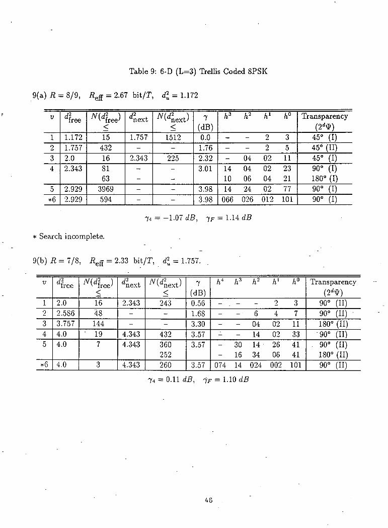
Table 9: 6-D (L=3) Trellis Coded SPSK
9(a) R = 8/9, ReS = 2.67 bit/T, <£ = 1.172
V
1234
5*6
4ee
1.1721.7572.02.343
2.9292.929
free)<
154321681633969594
^next
1.757-
2.343—
--
Wnext)<
1512-225
--
7(dB)0.01.762.323.01
3.983.98
h3 h? h1 h°
- - 2 32 5
04 02 1114 04 02 2310 06 04 2114 24 02 77066 026 012 101
Transparency
(2dtf)45° (I)45° (II)45° (I)90° (I)180° (I)90° (I)90° (I)
74 = -1.07 dB,
* Search incomplete.
9(b) R = 7/8, = 2.33 bit/T, <£ = 1.757.
V
I2
345
*6
^free
2.02.5S63.7574.04.0
.4.0
^free)<1648144
- 197
3
dnext
2.343--
4,3434.343
4.343
^next)<
243--
432360252260
7(dB)0.561.683.303.573.57
3.57
h4 h3 h2 hl h°
- . - - 2 3- • 6 4 7
- - 04 02 11- - 14 02 33- 30 14- 26 41- 16 34 06 41
074 14 024 002 101
Transparency(2dtf)
90° (II)90° (II)180° (II)
•90° (II). 90° (II)
180° (II)90° (II)
= 0.1145, 7F=1.10cZ5
48

9(c) R = 6/7, Refi = 2.0 bit/T, <PU = 2.0
V
123
4
*5*6
free
3.7574.04.0
4.0
5.7575.757
free)<288197
3
27280
dnext
-5.7575.757
5.757
--
next)<-
230414881200576528--
7(dB)2.743.013.01
3.01
4.594.59
h4 h* h2 hl h°
- - 2 32 5
02 06 13- 04 02 1710 04 06 2510 04 02 :W
60 24 20 06 II060 050 006 002 KM
Transparency
(2dV)180° (II)180° (II)90° (II)180° (II)90° (II)180° (II)180° (II)180° (II)
74 = 0 dB, 7F = 0 dB
49

10(a) R = 11/12,
Table 10: 8-D (L=4) TreUis Coded 8PSK
bit/71, <£ = 1.172
V
12345
dfree
1.1721.7572.02.3432.343
free)<5419442696327
next
1.757-
2.343-
2.929
next)<
14580-
2916-
110376
7(dB)0.01.762.323.013.01
h3 h2 h1 h°
- - 2 3- 6 4 5- 04 02 1110 06 04 2134 16 10 45
Transparency(2d#)45°45°45°45°45°
10(b) R= 10/11,
74 = -0.94 dB, 7F = 1-60 dB
= 2.5 bit/71, dl = 1.172.
V
12
345
*6
free
2.02.3432.3433.1723.515 .
4.0
free)<26204327784779442852
next
2.343— -3.172-
4.343
next)<
5832-312-
9828
7(dB)2.323.013.014.334.77"
5.33
h3 /i2 hl h°
2 3- 4 6 7
04 02 1114 04 02 2114 30 02 4116 24 10 47030 050 026 101
Transparency(2dtf)45°45°45°45°45°90°
- 45°
74 = -1.35 dB, 7F = 0.23 dB
50

10(c) R = 9/10, = 2.25 bit/T, d\ = 2.0
V
I2
3
4*5
free
2.3433.1724.0
4.04.0
free)<
2715652
164
next
3.172-
4.3434.6864.6864.3434.686
next)<
1092-
1404145864824306
7(dB)0.692.003.01
3.013.01
/i4 h3 h2 hl h°
- - - 2 3- - 6 4 5- - 06 02 11- - 02. 06 11- 04 06 16 2134 10 14 02 4124 14 04 06 41
Transparency
(2**)45°45°45°90°45°45°90°
10(d) R = 8/9,
74 = 0.51 dB, 7F = 1.23 dB
= 2.0 bit/T, <% = 2.0
V
012
34*5
^free
2.3434.04.04.05.1727.024
Wfree)<27521641251
^next
-4.6864.6864.686--
^VKext)<
-
1458648288-
-
7(dB)0.693.013.013.014.135.46
h4 h3 /i2 hl h°
- - - - -- - - -2 ..3- - 2 6 7- 04 02 12 1106 20 02 06 2122 30 24 02 43
Transparency(2^)
45°90°45°45°45°90°
74 = 0 dB, -IF = OdB
51

Table 11: 4-D (L=2) Trellis Coded 16PSK
ll(a) R = 7/8, ReS = 3.5 bit/T, d* = 0.304
V
123
4
5
6
dLe
0.4570.5S60.761
0.913
0.913
1.066
free)<25612864672154721329612965284848017088
dnext
-0.761
—
—
—
—
«ext)<-
1024
:
_
7(dB)1.762.843.98
4.77
4.77
5.44
h2 hl h°
2 3- 2 502 06 1304 02 1716 12 2316 04 2332 22 5726 04 53004 030 127060 004 127
Transparency(2d$)45°45°22.5°45°22.5°45°22.5°45°22.5° .45°
11 (b) R = 6/7,
7s =.-2.17 dB, 7F = 0.06 dB
= 3.0 bit/T, d* = 0.586
V
I2
3456
*ee
0.8901,1721.4761.7571.7812.0
t'ree)<1449324274326
rfnext
-1.476---
2.0852.062
- next)<-576---
11988162
7(dB)1.823.014.014.774.835.33
/i2 kl h°
2 32 5
04 02 1714 06 2306 16 53022 052 133046 014 103
Transparency(2d#)22.5°2.2.5°90°45°45°45°90°
7s = 0 dB, 7^ = 0 dB
52

Table 12: 6-D (L=3) Trellis Coded 16PSK
12(a) R = 11/12, ^ = 3.67 bit/r, <£ = 0.304
•y
12
34
5*6
rf?free
0.3040.4570.5860.609
0.7610.890
free)<
4023044530420830720180
^next
0.457-
0.609
—
--
next)<
8320-
1600
--
7(dB)0.001.762.843.01
3.984.66
h3 /i2 hl h°
2 3- 6 4 5
04 02 1114 04 02 2110 06 04 2114 24 02 77050 024 006 103
Transparency(2d$)
22.5° (I)22.5° (I)22.5° (I)45° (I)90° (I)45° (I)45° (I)
78 = -1.97 = 1.04 dB
12(b) R = 10/11, Refi = 3.33" bit/T, d\ = 0.457
V
12
345*6
- free
0.5860.738.1.0431.1721.1721.218
free)<
4518011255745920
^next
0.609--
1.195--
next)<
1168--
4500--
7(dB)1.082.083.584.094.09'4.26
h3 h* - hl h°
2 3- 6 4 7
04 02 1114 02 33
34 16 06 41010 046 060 105
Transparency(2d$)
45° (II)45° (II)90° (II)45° (II)22.5° (III)22.5° (III)
7s = -0.62 dB, TF = 0.84 dB
53
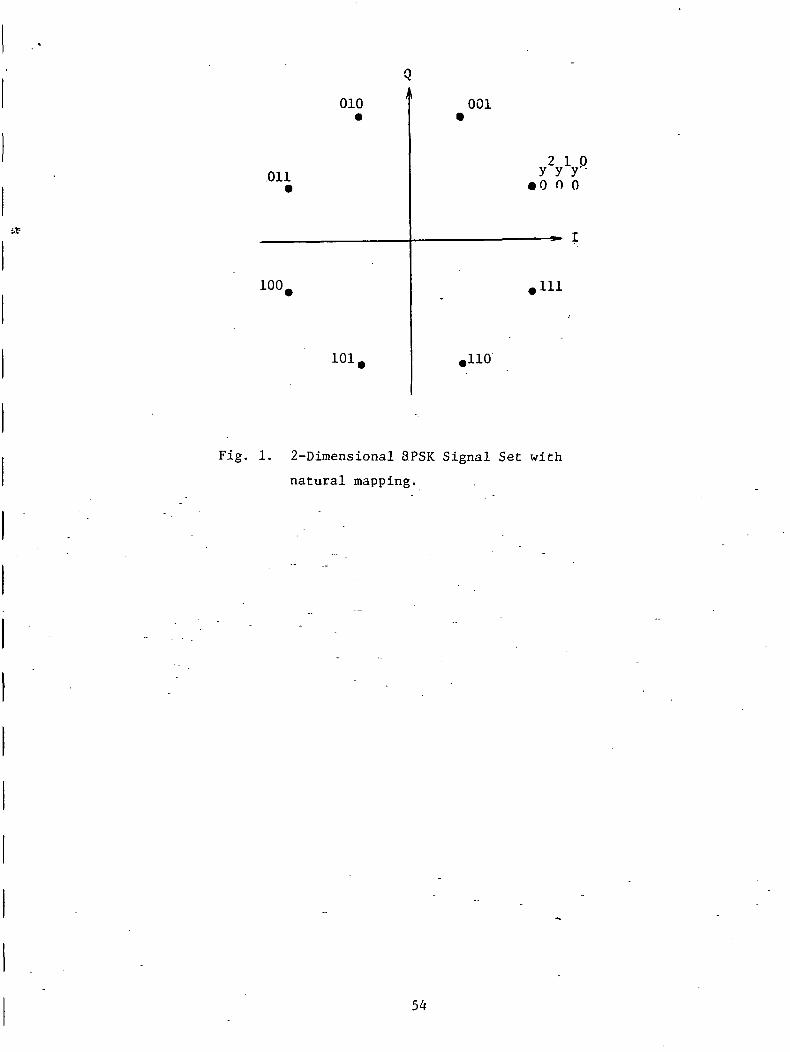
010
QI
Oil•
100.
101.
001
2 1 0y y yo n o
,111
,110
Fig. 1. 2-Dimensional SPSK Signal Set with
natural mapping.

,Ci,ti(0) =
m = 0 - m = 1
(CO/GO
m = 2.
(C0/C2)
Figure 2: A 2/2:way partition chain C0/Ci/C2 in the 2-D binary vector space.
55

fi(Co,C0,C2):
n(c0,c0,c2(2)):
fi(C0,Co,C2(3)):
0 .^0(00,0!, C2(l))
•ft(C0,C1(5),C2(5))
•n(C0,C1,C2(7))
= 0
Note: for p = 3 m2 = 0; Cm2(r) = C0,
= 2;
Figure 3: A 2/2/2 partition chain fi(C0, C0, C0)/n(C0l C0,in the 2 x 3 binary matrix space. -
C0| C,)/n(C0, Clf C2)
56

!f
P(C0,Co,C1(l))
P(C0,C0,C2)
P(C0,Co,C2(2))t
P(Co,C0,C2(l));
P(CD,C0,C2(3)):
P(C0,C1(4),C2)
0 XP(C0,C1(3),C2(3))
0.586p = l1.172
Note :Atp = 3 m2 = 0; Cm^(z] = C,m1 = l; Cmi(^) = C 1 ®[0 ,z 2 ©
• m0 = 2; Cmo(z) = C2©[z1 ,2°0
Figure 4: A three level 4-D SPSK signal set partition.
57

,P(C0, Co, 00,00;
o, Co, Co, C2
P(C0,C0,C0,C2(2))
•P(Co,Co,C1(4),C2)
0 >rP(Co,C0,C1>C2(2))
P(C0,C0,C1(6),Cj(6))
(Co,Co,C0,C2(l)):
0 ^P(C0,C0,C1,C2(1))
1 ^P(Co,C0,C1(5),C2(5))
0 ^P(Co,C0,..C1(3),C2(3))
V(C0,C0,Co,C2(3)):
p 0A 0.152
10.304
2.586
31.172
Note: Forp = 3m3 = 0; Cm3(z) = C0
m2 = 0; Cm2(z) = C0,m, = 1; CTOl(z) = d 0 [O,^2 © z° - 21]7,m0 = 2; Cmo(z) = C,®(z\z°®z l ] T . -
Figure 5: A three level 4-D 16PSK signal set partition.
58

•H OCO U
cuto
0)uVi(U
o
•M Ol-l .J
Q
•HCO
ooOJo.a.
<-r -H co
£ -w s
1
co•H•U |JC (UID -aV- Oa> u
u-i ojM-l JJ•H p.,Q
t-T f
<. '
O OX
CO
cuen
cocoo
PI
•H
36
00c
•H13OO
OM-l
6aiXJcn~p>-.CO
•oouc0)
01c(U
CJ3
360•H
59

oIIo
0113Oac<u
IS]
0)c0160
o<4-l
to
OO0)5-1a.
cai}-tai
H-lM-l•HQ
r^-
01
360
60

•a0)
.Mo<u.co
CU•OOOCHI
tflCO
O
Coo
CO
0)4JCO
en
oo
0)1-1300
•r-l
>v
T3CCO
61

N N
•O01
u0)
o
.c4-1•H3
01•oouc0)
COCO•H4-13,-!O
couo•H4-1CO
(LI
W
W3
_Qv«x00
O)(J
00tJ•H
cCO
62

ij?
cua.a.
Coc
o•H
300
63

L-l
1-1
l-l
1-1
Figure 10.: Parallel to serial converter.
64

-
-
~
H>
_^_
o -*•
_
o— *
^
0M m
TH
ATH
t
Hro
H
1 i
<
1 o
0
•— O10 1C
t '
^
to
<oNJ
J3
ID
-Q
O
U-J
it
0
10
.O
^
M
egi in
— o.0 .
^ '
01
•u
CO1
•uo
,>!
(-1
TJ•u
noI
T)Ov;
ft-
<
QO
•ou
01uo=c
o
f
o
cn
CM
U)
,—in
in
-
Oin
in
CM
Ol
0CJCwu
•H
CO
CO
CO
fc
o
— *•
j_ CM
O
-
o
*"— *•— f **
-
1 1
-1 -. H
J-l0)
a>CO
tfl
00-HCO
Q
o>-
ai•aooc
Ol
u-i•HQ
H
u•H
cnCO
01CO
cfl
00
COPHCO
ovO
CO
COM
0)
0)T3OOC
Ed
• 300•Hfa
CN
•accfl
CO0)
Ol-aoo
CcuCOo.cnCCO
•acCO
65

- 2 - 1 0 1 2
Figure 12(a): Coding gain verses complexity for multi-D 8PSK,
and 2-D bit/T.
* Code search incomplete
? Predicted codesV
Y(.dB)
6 '
5
4 -
3 -
•5 bit/T
•67 bit/T (6-D)
•X 2-75 bit/T(8-D)
"8-J3
4-
0 1 2 3 4 5 6 7 8
Figure 12(b): Coding gain verses complexity for multi-D 8PSK.
- y+k-log2L
8 °i 10 11 12
66

Y (dB)
6 -
6-D
2.33 bit
2.25 bit/T
0 3 4 5 8 9
Figure 12 (c): Coding gain verses complexity- for
multi-D 8PSK,
67

Y (dB)
6 i
3
2 -
1 •
4-D//Gf
0 1 2 6 7 8 9 1 0 .
Figure 13(a): Coding gain verses complexity formulti-D 16PSK and 3-D -bit/T.
Y (dB)
6' ' '
5 '
4 -
3 -
2 -
1
0
3-5 bit/T
3-67 bit/T3-33 bit/T
3 4 6 7 8
68

Appendix B
An Algorithm for Computing theDistance Spectrum of Trellis Codes

An Algorithm For Computing the DistanceSpectrum of Trellis Codes*
Marc Rouanne and Daniel J. Costello, Jr.Department of Electrical and Computer Engineering,
University of Notre Dame, Notre Dame, IN 46556
May 1, 1988
Submitted to the IEEE Journal on Selected Areas in Communications
Abstract
The performance of a trellis code can be accurately predicted from its distancespectrum. A class of quasi-regular codes is denned for which the distance spec-trum can be calculated from the codeword corresponding to the all-zero informationsequence. An algorithm to compute the distance spectrum of linear, regular, and -quasi-regular trellis codes is presented. In particular, it can calculate the weightspectrum of convolutional (linear trellis) codes and the distance spectrum of most ofthe best known trellis codes. The codes do not have to-be linear or regular. Thealgorithm is a bidirectional stack algorithm. We use the algorithm to calculate thebeginning of the distance spectrum of some of the best known trellis codes and to
-compute tight estimates on the first event error probability and on the bit errorprobability.
1 Introduction
The performance of a trellis code depends on the decoding algorithm employed and on the
distance properties of the code, i.e., the distances between codewords. The exact error
probability of a coded system cannot be calculated, even for simple trellis codes. However,
trellis code error probabilities can be estimated using simulations and performance bounds.
Simulations often require long running times and are only useful for short constraint length
codes. Performance bounds are the most common means of estimating the error probability
"This work was supported by NASA Grant NAG5-557. Part of this material was presented at theConference on Information Sciences and Systems, Princeton, NJ, March 1988.
1

of codes and of designing new coding schemes. The distance spectrum can be used to
compute performance bounds.
A trellis code, or trellis coded modulation (TCM), consists of a convolutional encoder
followed by a mapper. Figure 1 shows a typical trellis code as originally designed by
Ungerboeck [10]. This schematic representation was introduced by Forney et. al. [6].
An encoder state is characterized by the values of the past information bits stored in the
shift registers of the convolutional encoder. The incoming information bits determine the.
transitions or branches connecting one state to the other. During each signaling interval
T, the k information bits «*, . . . , u* enter the convolutional encoder and an n-bit subset
selector VT = (u*, . . . ,v") leaves the encoder. Subset selectors depend on the incoming
k information bits and on i/ past information bits only, where v is called the constraint
length of the trellis code. The mapper transforms the subset selector into a subset of channel
signals. The uncoded information bits u ^ , : , . . . , u^ then select one particular channel signal
from the selected subset. The set of possible channel signals is denoted by S.
A topological trellis is a trellis with no labels on the branches. A topological path Y =
{..., YT, YT+i,~...} through a topological trellis is a sequence of consecutive branches YT
which have not yet been assigned a signal. The topological branch YT is the rth branch in
Y and corresponds to the rth signaling interval since the beginning of Y. A channel path y
is defined by a topological path Y and a sequence of labels: y = {..., yT, T/T+I, •;-.}, where
yr is a branch in Y labeled with a channel signal in S. A channel path is a path through
a labeled trellis. The length I of a path is the number of consecutive branches that form'
the path, and it can be finite or infinite. We will sometimes call yr a signal although it is
more properly called a labeled branch, and we say that yr is the output signal during the
rth signaling interval. The context should make .clear when we mean a labeled branch or a
signal.
A labeling of a topological trellis associates a signal with each branch in the trellis. A
trellis labeling can be seen as the combination of a binary encoder and a mapper. A trellis
code is uniquely characterized by a topological trellis and a labeling. The most general
way to define a trellis code is by using a table which assigns a signal to each branch in the
trellis. In other words, a trellis code is the set of all labeled trellis branches for all signaling
intervals (to construct a trellis code, one only needs to label trellis branches with channel
signals).
Given two signal or subset sequences y = ( . . . , j/t, j/2, • • •, Z//, • • •) and y = ( . . . , ylt T/?, • • •,
2 / < > ' ' ')> (y, y) is a first event error of length / if YT = Yr for T < 1, Yr ^ YT for 1 < r < /,
2

<s
and Yr = YT for T > /, i.e., the error event starts when the two paths diverge and ends
when the two paths remerge for the first time. Figure 2 shows a first event error of length
/ (the correct and incorrect paths remerge after / branches).
The performance of a trellis code depends on the distribution of distances between
encoder output sequences (code words) corresponding to distinct encoder input sequences.
In particular, if y = (yi, . . . , yT, . . .} and y = {yi, . . . , yT, . . .} are sequences of signals from
5, the squared Euclidean distance d(y, y) satisfies
where d(yT,yr] is the squared Euclidean distance between two channel signals yr and yr.
The distance between two code words determines the likelihood of decoding one code word
when the other one was sent. For an AWGN channel, the squared Euclidean distance
between two signal sequences y and y determines the likelihood of receiving y given that
y was sent.
A union bound on the first event error probability Pe of trellis codes may be obtained
by summing the error probability over all possible incorrect paths which remerge with all
possible correct paths [12]. At any time unit, Pe is bounded by_
P*< £ A& H™= . (2)d=dfree \V2N0J
where d represents the squared Euclidean distance between signal sequences, Ad is the
average number (multiplicity) of code words at distance d from a specific code word, where
the average is taken over all code words in the code, dfree is the minimum free squared
Euclidean distance of the code, N0 is the one-sided noise power spectral density, and Q(.)
is the Gaussian integral function Q((3] = /~ e"*2/2;^—. Equation (2) can be rewritten as
pe< ; Adpd,d=d,Tfe
where Pd = Q(d/\/2N^) is the two code word error probability for distance d.
The bit error probability PI, is the average number of bit errors per decoded information
bit. Equation (2) can be modified to provide a bound on P& by weighting each term Pd by
the average number B<i of information bits on all paths at distance d from the correct path
[12]. Hence, at any time unit, P^ is bounded by-
pb< f; Bdpd. . (3)

A spectral line is defined by a distance d and its average multiplicity AJ. The set of all
spectral lines is called the distance spectrum of the code. If the code is linear, AJ is the
number of code vectors of weight d in the code, and the distance spectrum is commonly
called the weight spectrum of the code [8].
The first event error probability can be estimated in terms of the free distance dfree of
the code. Trellis codes with a large free distance are optimum at large signal-to-noise ratios
(SNR). At moderate SNR, the optimality of the code depends on the first few spectral lines
of the code, especially for non-binary, non-regular trellis codes whose distance spectra are
relatively dense. This means that the codes with the best free distance may not be the
codes that perform the best for moderate SNR.

2 Quasi-Regularity
Given a signal set S and an equivalence relation (R) defined between elements of S, two
elements x and y in S belong to the same equivalence class of (R} if and only if they satisfy
(R), which is denoted xRy. An equivalence sequence (Ri}/(R^)/ . . • /(Rr) on S is a set of
r equivalence relations defined on elements of 5" which satisfy
1 < * <j < r, V- x,yeS, xR,y => xR{y, (4)
where r is the number of levels in the sequence. The equivalence classes generated by
are called subsets of S at level i and form a partition chain of the signal set.
A trellis code is linear for an operation called a sum iff the sum of any two codewords
is a codeword. For example, convolutional codes are linear because the modulo-two sum
of any two codewords gives a binary codeword [8]. Linearity can be defined with respect
to an equivalence relationship defined on signals [5]. The equivalence classes defined by a
relation (R) partition the signal set into subsets. Let a sum be defined on these subsets
and a trellis code be labeled with subsets. The codewords of such a code are sequences
of subsets, and the code is linear with respect to (R) iff the sum of any two codewords
(sequences of subsets) is another codeword (sequence of subsets).
When the trellis is labeled with subsets, the "sum of signals need not be defined and
linearity with respect to (R) is less stringent than linearity with respect to signals. When
the signal set is given the structure of a group and partitioned into.cosets, linearity with
respect to cosets is the same as linearity with respect to signals, because then the sum is
defined, from the group structure. This can be shown as follows. Suppose that a code is
linear with respect to the cosets of a subgroup of the signal set. Consider two sequences
of signals through the trellis: they define two sequences of cosets whose sum is a codeword
because the code is linear with respect to cosets. The sum of the two sequences of signals
corresponds to that codeword and must be a channel path through the trellis, which proves
that the code is linear with respect to signals.
A trellis code is regular iff the distance between two codewords that correspond to
distinct information sequences depends only on the binary sum of the two information
sequences (we assume that the distance is an additive metric). Once again, codewords
can be sequences of subsets and regularity can be defined with respect to an equivalence
relation [3]. In such a case, the distance between subsets is the minimum distance between
the signals in the subsets.

Regularity makes the calculation of the distance properties of a code feasible. For regular
codes, the set of distances of incorrect paths from a correct path does not depend on the
correct path. This means that the distance properties of regular codes can be calculated by
assuming that an arbitrary correct path was sent. In practice, it is assumed that the path
generated by the all-zero information sequence was sent. This assumption considerably
reduces the complexity of distance spectrum calculations, since only one among many
correct paths must be evaluated. Unlike linearity, regularity with respect to cosets is not
equivalent to regularity with respect to signals. There are no known bandwidth efficient
codes that are regular with respect to signals, and it can be conjectured that none exist.
However, there exist many known bandwidth efficient codes that are regular with respect
to cosets [3] and [5].
Ungerboeck was the first to show that for certain non-regular codes the free distance can
be calculated by assuming that the all-zero information sequence was sent [10]. This can
be generalized to any trellis code, regular or not, but leads to far more complex algorithms
than the one presented in the next section. Instead, we define the class of quasi-regular
codes to be non-regular codes for which the distance spectrum can be calculated with a
relatively simple algorithm by assuming that the all-zero information sequence was sent [9].
A mapping of signal selectors onto a signal set is regular iff the distance between two
signals depends only on the Hamming distance between their signal selectors."Forexample,
there is no regular mapping of eight signal selectors onto an 8-PSK signal set. Similarly,
there is no regular mapping from four signal selectors onto 4-PAM or from 16 signal selectors
onto 16-QASK. Figure 3 shows a non-regular mapping onto 8-PSK. This particular mapping
is known as the natural mapping. The regularity of a mapping can also be defined with
respect to subsets.
Let s and s be two states in a trellis code, and a signal selector error vector e the binary
sum of two signal selectors. Then the distance polynomial Ps^<e(x) represents the set of
distances between signals generated from s and J and whose signal selectors differ by e.
The polynomials P3ls,e(x) afe only defined for those e for which there exists a branch that
leaves s and a branch that leaves s whose signal selectors differ by e. Let j/(v) be the signal
in 5 whose signal selector is the binary n-tuple v. Then the polynomial P3tst<,(x) is given
by/W*) = E P(v|s)z*(^(u+e)],
v|S
where p(v\s) is the probability of the signal selector v given that the encoder is in state

s and d[y(v),y(v + e)] is the squared Euclidean distance between y(v) and y(v + e). For
example, for 8-PSK, if y(OOO), y(010), y(100), j/(110) leave state s and y(001), j/(011),
j/(101), y(lll) leave state 3, only four error vectors e are possible between the branches
that leave 5 and 3 (Figure 3). These four error vectors are 001, Oil, 101, and 111, and the
corresponding distance polynomials satisfy
r\ — -faif J — U/ ^
These polynomials look similar to the "weight profiles" defined by Zehavi and Wolf in a
paper on the performance of rate k/(k + 1) trellis codes mapped by set partitioning [14].
However, weight profile polynomials are defined from a knowledge of the signal set and the
mapper only, whereas the above polynomials are code dependent. This allows the definition
to apply to a large class of codes of any rate, which includes the codes treated by Zehavi
and Wolf.
A trellis code is quasi-regular iff (i) it consists of a linear binary encoder followed by a
mapper and (ii) for all e and all pairs of states (si,5i) and (32,52), Psiij1)e(x) = PS2ts2,e(x)
(provided that the two polynomials are denned). By definition, for regular codes, the
distance between signals depends only on the binary sum e of their signal selectors (PSts,e(x)
is "a monomial which does not depend on s or 3), and regular codes are quasi-regular. Since
linear codes are regular, they are also quasi-regular. In the previous example of trellis
coded 8-PSK, the two polynomials P3,3,oii(x) and P3,3,m(x) are n°t monomials, and the
code cannot be regular. However, it is quasi-regular because P3>sie(x) does not depend on
(3,5).
Let V be the set of signal selectors generated by the underlying binary code and T/(V)
be the signal in S selected by some v c V. To each signal selector error e corresponds a
unique set of distances {d[y(v),y(v®e)],veV}. We define w(e) as the minimum distance of
this set. Originally, Ungerboeck [10] computed the free distance of his codes by assuming
that the all-zero information sequence was sent and replacing d[y(v),y(v© e)] with a lower
bound on to(e) in the computation. In a more recent publication, the free distance was
computed directly from the values of w(e) [11]; Similarly, it will be shown later that the
distance spectrum of quasi-regular codes- can be computed from the all-zero path by using
the u>(e)'s.

The set of signal selector error vectors e for which there exists a v such that d[y(v), y(v©
e)] > w(e) is denoted E. For example, for the mapping in Figure 3, E = {Oil, 111}, which
means that the distance between signals whose selectors differ by Oil or 111 is not unique.
A distance spectrum contains all the distances between codewords, even infinite dis-
tances between codewords that never remerge. In order to avoid dealing with these infinite
distances, we consider only paths of any length / for any finite / > 0. The distance spectrum
) at depth /of a trellis code satisfies
y y
where y = {yt, . . . , y{] is a correct path of length /, y = {yl5 . . . , yi] is an incorrect path
diverging from y at time 1 such that (y,y) is a first event error of length /, and p(y) is the
probability of the correct path y. SP^(x) represents all possible distances between paths
of length / which leave the same state at time 1. The distance spectrum is entirely defined
by 5pW(x) for all /.
The worst case distance spectrum of a trellis code is derived from the distance spectrum
of the code by replacing the distance d[y(v),y(v)] by w(v ® v) for all pairs of signals
(j/(v),?/(v).). Two paths have the same worst case distance if they have the same distance
calculated using the io(e)'s and if they have the same number of occurrences of e for
each e e E. This means that the worst case distance spectrum contains some topological
information about paths.
.. Most of the best known trellis codes consist of a binary -linear convolutional encoder
followed by a mapper. In this case, the worst case distance spectrum has a simple expres-
sion.
Lemma 1: The worst case distance spectrum at depth / of a trellis code which consists of
a binary linear convolutional encoder followed by a mapper satisfies:
SP£>(*) = E II ^(er)>e?40 T=I
where the sum is over all nonzero signal selector error sequences e = {el5 . . . , e/} of length
/ generated by the underlying code and T represents a time index.
Proof: Since the underlying code is linear, for any correct path y, the set of error events
(viy) can be described by the nonzero codewords of the code. The Lemma follows as
a simple consequence of the definitions of the distance spectrum and of the worst case
distance spectrum.

The next two Lemmas are also immediate consequences of the definitions of the distance
spectrum and of the worst case distance spectrum.
Lemma 2: The worst case distance spectrum of a trellis code which consists of a binary
linear convolutional encoder followed by a mapper can be computed by assuming that the
correct codeword corresponds to the all-zero information sequence.
Proof: The set of selector error sequences is exactly the set of binary codewords of the
underlying code. Thus, the worst case distance spectrum depends only on the underlying
code and on the distance function u>(.). The distance function tu(.) depends only on the
signal set and the mapping and not on the regularity of the code. Since the codewords of a
linear code can be calculated by assuming that the all-zero information sequence was sent,
the worst case distance distance spectrum of any trellis code generated by a binary linear
convolutional encoder can be computed by assuming that the all-zero information sequence
was sent.
Lemma 3: The worst case distance spectrum and the distance spectrum of a regular code
which consists of a binary linear convolutional encoder followed by a mapper are equal.
Proof: Given a correct path y, to each incorrect path y corresponds a unique nonzero error
sequence e, which is a codeword since the sum of "any two codewords in a linear code is a
codeword. Therefore, the sum over y in (5) can be replaced with a sum over e ^ 0. Since
the code is regular, d(y r,yT) = w(er), where eT. is the..binary sum of the signal selectors of
yr and yT. Equation (5) can then be rewritten as -
= £T=I y
wM, (6)
since the sum over e ^ 0 does not depend on the correct path y. Equation (6) is exactly
the worst case distance spectrum of the code, which proves the Lemma.
The next Theorem is the backbone of the algorithm for computing the distance spectrum
of trellis codes. The proof of the Theorem consists of expressing the distance spectrum of a
quasi-regular code as a product of the polynomials Pe(x] defined above. Then this product
can be computed from the worst case distance spectrum, provided that the underlying code

is linear. Since the worst case distance spectrum of quasi-regular codes can be computed
by assuming that the all-zero information sequence was sent, the distance spectrum can
also be computed from the all-zero information sequence. The idea of the proof is to group
together all the error events that correspond to the same sequence of signal selector errors.
The proof is by induction on the length of this error sequence. For each selector error
in a sequence, the distance can be computed using the polynomial Pe(z), provided that
the error e is the sum of two signal selectors that leave the correct and incorrect states,
respectively.
Theorem 1: The distance spectrum of a quasi-regular code can be computed from its
worst case distance spectrum.
Proof: The proof of Theorem 1 is given in Appendix A.
The proof of Theorem 1 shows that to compute SP^(x) it is sufficient to replace xw^
in SP$(x) with Pe(x) whenever e e E, which can be done by knowing the number of
occurrences of each e e E for each incorrect path. Theorem 1 is similar to Zehavi and
Wolf's first Theorem which states that the distance spectrum of Ungerboeck's codes can
be computed from a state diagram with 2" states, where v is the constraint length of the
code [14]. The proof given in their paper is simpler than the proof given above because it
applies to a smaller class of codes.
The main advantage of our approach is that it allows the computation of the per-
formance of trellis codes with significant constraint lengths, whereas Zehavi _and Wolf's
approach requires the computation of a modified transfer function and is limited only to
very small constraint lengths. The algorithm described in the next section computes the
worst case distance spectrum of quasi-regular codes by assuming that the all-zero infor-
mation sequence was sent. Hence, the distance spectrum of quasi-regular codes can be
computed by assuming that the all-zero information sequence was sent, although unlike
regular codes, all correct paths do not give the same distribution of distances.
Lemma 4: Ungerboeck rate k/(k + 1) systematic codes are quasi-regular.
Proof: Because of the rate of the codes, half the signals in the signal set leave each state
in the trellis. Two cases can occur: either s and s are labeled with the same half of the
signal set, or they are labeled with different halves. If (s^Si) and (52,52) correspond to the
same case, then PSlislie(x) = PJ7ij2i(.(x). If the two pairs correspond to different cases, then
one of the two polynomials is not defined because distinct cases correspond to distinct sets
10

of signal selector errors (distinct least significant bits in e). This proves the Lemma.
Ungerboeck rate k/(k + l) systematic codes are quasi-regular, which allows fast distance
computation and code search algorithms [10]. Quasi-regularity does not require that the
set of distances of paths from a correct path is the same for all correct paths. It only
requires that the distance spectrum is calculable from the set of distances from the all-zero
path.
3 The Algorithm
The algorithm is a modified version of Chevillat's stack algorithm for calculating the dis-
tance profile of convolutional codes [4]. Bahl and Jelinek [1] and later Larsen [7] used
a bidirectional algorithm for calculating the free distance of convolutional codes which
extends paths forward and backward simultaneously. Our algorithm is also bidirectional.
These previous algorithms terminate when the free distance is reached, whereas our
algorithm continues to compute the higher distance spectral lines. It keeps track of the
number of paths with the same distance and of the total information sequence weight along
these paths. All the paths that reach a given state are retained, whether they have different
distances or not. (In conventional free distance computation algorithms, only the path with
the smallest distance is retained.) When a merger is detected, two cases can occur: (1) if
no previous merging paths had a distance equal to that of the new merger, a new spectral
line is created, or (2) if the distance of the merging paths is equal to the distance of an
existing spectral line, the multiplicity of the line is incremented. Naturally, this .algorithm^
requires more computation and storage than conventional free distance algorithms because
no paths are discarded.
The complexity of the stack decoding algorithm depends on the number of paths that
must be extended and not on the constraint length of the code. The multiplicity of a
spectral line of distance d is achieved when all remaining paths have a distance larger
than d. In most codes, the longest free distance paths are several constraint lengths long.
Similarly, it can be conjectured that the longest paths that have a certain distance are
several constraint lengths longer than the shortest paths with the same distance.
For example, for a code whose shortest register length is 3, the shortest mergers are 4
branches long. The longest error event with the free distance will be about 20 branches
long.. If the code is a rate 2/3 code, the number of paths of length 20 is 420 ~ 1012.
Computing the free distance consists in'finding the path among these 1012 paths that has
11

the smallest distance. Computing the multiplicity of the free distance consists in calculating
the number of paths whose distance equals the free distance, and so on for each spectral
line. Obviously, this can can be an enormous task, even for simple codes.
A forward path leaves the all-zero state on a non-zero branch in the forward direction,
and once it has remerged with the all-zero path it is discarded. A backward path leaves the
all-zero state on a non-zero branch in the backward direction, i.e., it consists of a succession
of branches that lead to the all-zero state.
A path is determined by the following information:
3
dI
WAs,d,e,W
Bs,d,e,W
Direction (fw or bw)Terminal state
DistanceLength
Array of occurrences of eMultiplicity
Information weight
eE
The terminal state s is the last state reached by a path of length I branches from the
all-zero state for a forward path and to the all-zero state for a backward path. The distance
d is the worst case distance along that path, i.e., the distance calculated from the u;(e)'s.
The array W of-occurrences of e e E is the number of branches on the incorrect path for
which the signal selector was e for each e e E, because the signal selector on the correct
path is always zero. Two paths are identical iff they have the same structure, i.e., the same,
distance d, length /, and array W. 'The multiplicity ASi^e,w is the number of identical paths
ending in state s with distance J, length /, and array W. The information weight Bs^,e,w
is the average of the information weights of all the identical paths (although the paths
are identical, since they correspond to different topological paths, they may have different
information weights).
In the stack algorithm, an ordered stack of previously examined paths with different
parameters is stored. For the bidirectional algorithm, two stacks are necessary, one for each
direction. Each stack entry contains a path with all its information. Paths are ordered by
decreasing distances and lengths. Paths with the same metrics and lengths but distinct
terminal states or arrays W are stored on a last in, first out basis within the stack. This
does not affect the efficiency of the algorithm, but accelerates the searching and sorting
in the stack. The top path in the stack is the mostjikely to give the free distance or the
shortest merging distance among all the paths in the .stack, which is why it is extended
first.
12

Each complete sequence of steps consists of extending the top path in the stack by
computing its 2fc successors. The terminal state cannot be the all-zero state because it must
reach the all-zero state through the terminal state of a path from the opposite direction.
If one of the successors reaches the all-zero state directly, it is discarded. Assume, without
loss of generality, that a forward path is extended. Then three situations may occur:
(i) The state is not a terminal state for any forward path. Then a new entry is created
in the stack of forward paths to store the new path and its parameters.
(ii) The state is the terminal state of one or more forward paths. Compare the distance,
length, and W of the two or more paths. If the new path is not identical to any old
path create a new entry. If it is identical to an old path, increment the multiplicity and
information weight of that path.
(iii) The state is the terminal state of one or more backward paths. The path is then
merged with these backward paths to form one or more error events.
A forward path can reach the all-zero state only through the terminal state of a backward
path, because all the branches that leave a state in the middle of a backward path have been
extended. Thus, it is impossible to reach this middle state without following an extended
branch.
The spectral lines are stored by decreasing distance. Every time (iii) occurs, an old
spectral line is incremented or a new one is created. The distance of an error event is the
sum of the forward and backward distances, the length, is the sum of the lengths, W is the
sum of the Ws, the multiplicity is the" product of the multiplicities, and the information
weight is Bjw + Bi,w, where Bjw and B\,w are the forward and backward average information
weights.
There is no specific time for the algorithm to terminate. It depends on the number
of spectral lines required by the user, or on specified maximum path lengths or distances.
Once the algorithm is terminated, the worst case distance spectrum is converted into the
distance spectrum of the code, and each worst case spectral line is expanded into many
new spectral lines [9j. . .
Each worst case spectral line (d, Ad, W) is expanded by replacing all possible combina-
tions of the w(e)'s for which e 6 E by the other possible distances between signals whose
selectors differ by e. For example, for 8-PSK, E has two elements, Oil and 111, and if the
W~of a particular worst case spectral line contains the two occurrences 1 and 3, it means
that e = Oil occurred once, and e = III occurred'three times along each path represented
13

by this spectral line. Since each element in E corresponds to two possible distances (for
8-PSK), there are 16 ways of combining these distances on the four (1 + 3) branches that
correspond to e e E. This means that this particular worst case spectral line can be broken
into 16 lines. The distance of each line is found by replacing w(e) by the other possible
distances for all e e E.
The probability of a distance that corresponds to a specific e e E is given by the coeffi- .
cient of that distance in Pe(x). For example, if Pe(x) — l/2x*° + 1/2Z*2, the probabilities
of SQ and 8-2 are both 1/2. For each one of the 16 lines in the above example, there are
four distances that correspond to a signal selector from E. The probability of having a
specific set of four distances is the product of the probabilities of the individual distances
computed from the corresponding Pe(x)- Then the average multiplicity of each new line
among the 16 lines is the product of Aj, and the probability of each of the four distances.
If the probabilities of the various distances are equal for all e e E, the 16 lines will have
the same average multiplicity.
The algorithm
Step 1. Load the stack with the origin node, with distance zero, length 0, and multiplicity 1.All the other parameters are set to zero. Enter the number N of desired spectrallines.
Step 2. Compute the metric, length, multiplicity, information weight, and Ws of thesuccessors of the top path in the stack.
Step 3. Delete the top path from the stack.
Step 4- For each successor, check if it merges and update the merger information [(iii)].
Step 5. Insert the new paths in the stack, and rearrange the stack in order of decreasingdistance and length [(i) or (ii)].
Step 6. Output all the new spectral lines whose distance is smaller than the sum of theminimum forward and backward distances. If less than N spectral lines have beenfound, then change direction and repeat steps 1 to 6; otherwise, stop.
Figure 4 shows the first four forward and backward steps. The bold line represents the
correct path (the all-zero path). The trellis code has four states. Step la: one forward
path is extended (no remerging because state s^ has not yet been reached). Note that the
all-zero branch is not extented. Step Ib: one backward path is extended (no remerging
because state s3 has not yet been reached). Again, note that the all-zero branch is not
extended. Step 2a: the top forward path which terminates at Si is extended to 32 and 53.
One successor terminates at 52, which has been reached by a backward path, so a merger
is found (dashed line). Step 2b: the backward path that terminates at s2 is extended to
14

reach Si and s3 (one merger through 53). Step 3a: the forward path that terminates at 53 is
extended to reach s2 an(l 53 (one merger through s3). Step 3b: from sl5 only one backward
branch is extended because paths are not allowed to reach the all-zero state directly. A path
must remerge with the all-zero path through a terminal state from the opposite direction.
This ensures that mergers are not counted several times. Since 53 terminates two forward
paths, two mergers are found. Step 4a: again only one branch is extended because the
other one reaches the all-zero state directly (no mergers because Si is not the terminal
state of any backward path). Step 4b: the backward path that terminates at s3 is extended
to reach $i and s3 (one merger is found per new state).
The beginning of the distance spectrum can be used to upper bound the first error event
probability and the bit error probability of trellis codes. We calculate these performance
bounds for the some of the best known codes [10]. Figure 5 shows coded 8-PSK for con-
straint lengths 4, 6, 8, and 10 compared to uncoded QPSK. Figure 6 shows the distance
spectrum of 16 state coded 8-PSK. The free distance of this code is 5.13, and the multiplic-
ity of the free distance is 2.25, i.e., on the average, 2.25 incorrect paths are distance 5.13
from the correct path. The next spectral line "is relatively far from the free distance, and
its multiplicity is still moderate. This means that for high enough SNR, the free distance
is a relatively accurate indication of the.performance of this particular code. The larger
spectral lines are less spread out than the smaller spectral lines. This is a common property
of trellis codes, as opposed to convolutional codes where the spectral lines are separated by
integer distances. Note that the multiplicities of the large spectral lines are large.
We have also noted that the distance spectrum of regular codes is usually denser than
the distance spectrum of non-regular codes for the smaller spectral.lines. This is because
the free distance and most of the smaller spectral lines in a non-regular code are exceptional
events and do not occur for all correct paths. Figure 7 shows a comparison of the simulation
results performed by Ungerboeck [10] with the performance bounds computed from the
distance spectrum. The practical ranges where these codes may be used are below error
probabilities of 10~5. For such low probabilities, simulations become difficult, and the
distance spectrum bound is a good alternative. It is much tighter than estimates based on
the free distance alone.
15

4 Conclusion
A class of non-regular codes, called quasi-regular codes, was defined whose distance spec-
trum can be calculated by assuming that the all-zero information sequence was sent. Con-
volutional codes and regular codes are both quasi-regular, as well as most of the best known
trellis codes. An algorithm to compute the distance spectrum of quasi-regular trellis codes
was presented. Tight performance estimates can be calculated from the first few spectral
lines of most of the best known codes, and several examples show that this is an attractive
alternative to simulations.
5 Acknowledgement
We wish to acknowledge the help of Mr. Christian Schlegel in preparing the program used
to compute the distance spectrum of trellis codes.
16

Appendix A
A Proof of Theorem 1
It is sufficient to prove that the distance spectrum at any depth / of a quasi-regular code can
be computed from its worst case distance spectrum at depth /, since the distance spectrum
can be computed from the distance spectra for all /. The distance spectrum at depth /
satisfies
sp%) = Ep(y)EII*%r'H (A.I)y y T=I
where (y, y) represents the / branches of a first event error of length /. A path y of length
/ defines a unique state sequence s == {SQ, Si, . . . , s/} of / + 1 states (note that two different
paths may have the same state sequence if the trellis has parallel transitions). Let s;_i and
s/_! be the / states of a correct and incorrect path, respectively. The .paths y whose I
state is the specific state 5;_i are denoted by y|s/-i. In (A.I), the correct paths that reach
the same state s;_i are grouped together and the incorrect paths that reach the same state
J;_i are grouped together. Then,
sPw(*)=£K*-i)E'S;p(yl*'-i) E Rxd(y^}-si-i *i-iy|«i-i- - y|si-i T=l
Let y/_! denote the first / — 1 branches of y. Then a path y can be broken into y/_a
and iji. Given a state s/_i, the probability p(y|s;_i) of a path y of length / is p(y|sj_i) =
p(yt-i\si-i)p(yi\si-i}, i.e., the probability of the path is the product of the probability of
reaching state s/_! times the probability of the last branch of y (which leaves state s^).
Therefore
E Xy/-il'i-i) E E pfaM E R*«»Mi-il«i-i yi-i|ai-i yiki-i yil«i-iT=1
E X*-:) E *d(*A} E p(y/-ik-0 E R *d(yT'iki-i vi\si-i yi-iki-i y,_i|s (_1T=i
E E pWti-jxWM*^eilsi.Lii.i v\s t- l
E Kyi-il^-0 E R***"™, (A.2)
17

where e/|5/_1? J /_ j is one of the signal selector errors between branches that leave .?/_! and
£/_i. The fourth sum can be replaced with the polynomial Ptts,ei(x) so that (A.2) becomes
sp(0(z) = EX*-i)E E P>^W E p(y<-il*-0 E E^'^-*i-i s t_i ei\3i-i,st-i yi-i|«i-i yi-il'i-i1"-1
Because the code is quasi-regular, Pa,s,ei(x) does not depend on 5 and J, provided that e\
is a signal selector error between two branches that leave s and s, respectively (otherwise
the polynomial is not denned). This allows us to switch the summations over the states
s;_x and 3;_i with the summation over e/, so that
e' (»i-ii$i-i|ei) yi-i l*i-i yi-i 1*1-1 T=1
where (sj_i, J/_i|e/) is any pair of states generating signal selectors that differ by e\. All the
first event errors of length / that reach states s/_! and 5/_! and differ by e/ can be grouped
together. These error events are denoted by (y,y)|e/ in the next equation. Also PSis,et(x)
can be written as Pe|-(x), since it does not depend on s and J. Therefore
spW(x) = pei(x) E p(y/-0 H "^ (A-3).. " . e' (y,y)|ei T=1 " .
From (A. 3) and the definition of the distance spectrum at depth /,
EXyori^^^^E^,^) E p(y/-i) Iiy(y^r)- -• (A.4)(y.y) T=l ' gi (y,y)h_ . T=1 " " -
The same procedure can be repeated with the right side of (A.4) to express the distance
spectrum at depth / as a function of a sum over error events (y, y) conditioned on two .
consecutive time intervals (i.e., conditioned on e\ and e/_i). Furthermore, this result can
be extended by induction on the number of signal selector errors on which the beginning
of the error event is conditioned to obtain for any ! < « < / — !
E - XyOn^^E^-C*) E Xy-On^'H (A.S)(y,y)h ..... e.,+1 T=I e« (y,y)|ei,...,e« T=I
where (y, y)|ej, . . . , eK+i is a first event error of length / whose (/c + l)tn . . . rn branches are
labeled with signals whose selectors differ by e;,...,e«+1. In particular, for « = 1, (A. 5)
becomes
E PMlI^'^E^z). " (A.6)
IS

Hence from (A.3), (A.4), (A.5), and (A.6), we obtain
where the summation is over all nonzero signal selector error sequences e of length /. Note
that when er does not belong to the set E, then Per(x) = x™^ . Assuming that SP$(x]
can be computed, then the distance spectrum can be calculated from SP$(x) by replacing
per(x] for each eT e E. This concludes the proof.
19

References
[1] L. R. Bahl and F. Jelinek, "Rate 1/2 Convolutional Codes with Complementary Gen-
erators", IEEE Trans. Inform. Theory, Vol. IT-17, No. 6, pp. 718-727, November 1971.
[2] E. Biglieri, "High-Level Modulation and Coding for Nonlinear Satellite Channels",
IEEE Trans. Commun., COM-32, pp. 616-626, May 1984.
[3] A. R. Calderbank and N. J. A. Sloane, "New Trellis Codes", IEEE Trans. Inform.
Theory, IT-33, pp. 177-195, March 1987.
[4] P. R. Chevillat, "Fast Sequential Decoding and a New Complete Decoding Algoritlll-
inois Institute of Technology, Chicago, IL, 1976.
[5] G. D. Forney, Jr., "Coset Codes I: Geometry and Classification," IEEE Trans. Inform.
Theory, to appear.
[6] G. D Forney, Jr., R. G. Gallager, G. R. Lang, F. M. Longstaff, and S. U._ Qureshi,
"Efficient Modulation for Band-limited Channels." IEEE J. on Selected Areas in Com-
munication, SAC-2, No. 5, pp. 632-647, Sept. 1984.
[7] K. J. Larsen,-"Comments on 'An Efficient Algorithm for Computing Free Distance',"
IEEE Trans. Inform. Theory, Vol. -IT-19, pp. 577-579, July 1973.
[8] S. Lin and D. J. Costello, Jr., Error Control Coding, Prentice-Hall, Englewood Cliffs,
N.J., 1983. •-
[9] M. Rouanne, "Distance Bounds and Construction Algorithms for Trellis Codes," Ph.D
Thesis, University of Notre Dame, Notre Dame, IN, 1988.
[10] G. Ungerboeck, "Channel Coding with Multilevel Phase Signals," IEEE Trans. Inform.
Theory, IT-28, pp. 55-67, Jan. 1982.
[11] G. Ungerboeck, "Trellis Coded Modulation with Redundant Signal Sets - Part I: In-
troduction and Part II: State of the Art," IEEE Communications Magazine, Vol. 25,
no. 2, pp. 5-21, Feb. 1987.
[12] A. J. Viterbi and J. K. Omura, Principles of Digital Communications and Coding,
McGraw-Hill," New York, 1979.
20

[13] L. F. Wei, "Trellis-Coded Modulation with Multi-Dimensional Constellations," IEEE
Trans. Inform. Theory, IT-33, pp. 483-501, July 1987.
[14] E. Zehavi and J. K. Wolf, "On the Performance Evaluation of Trellis Codes," IEEE
Trans. Inform. Theory, IT-33, pp. 196-202, 1987.
21

BINARY ENCODER MAPPER
CONVOLUTIONALENCODER
v:
v» :
SUBSETSELECTOR
S / S, / • • • / Sr
IS / Sr| = 2"
SUBSETAT LEVEL r
k - k UNCODED BITSSIGNAL
SELECTOR
CHANNELCODING
SOURCECODING
Figure 1: Schematic representation of a typical trellis code.
22.

FIRST ERROR EVENT
CORRECT PATH
INCORRECT PATH
Figure 2: A first event error.
23.

on 001
too
101 • 111
Figure 3: A non-regular mapping onto 8-PSK.
24.

FORWARD PATHS BACKWARD PATHS
So
(la)
(2a)
CORRECT PATH
MERGERS
' s,
(25)
(3a) (35)
(4a) (4b)
Figure 4: Eight iterations of the algorithm.
25.
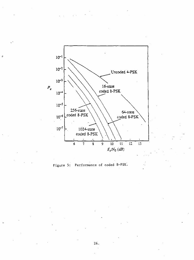
16-statecoded 8-PSK
256-stateceded 8-PSK
1024-statecoded 8-PSK
Uncoded 4-PSK
KT9 -
io-7-
64-stateccxied 8-PSK
6 7 8 9 10 11 12 13
Figure 5: Performance of coded 8-PSK.
26.
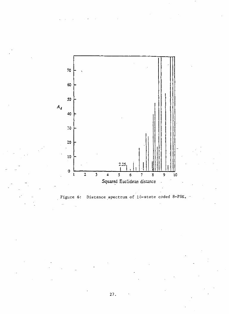
70
60
50
40
20
20
10
2.25I I I
3 4 5 6 7 8
Squared Euclidean distance
9 10
Figure 6: Distance spectrum of 16-state coded 8-PSK,
27.

10-l
10--
io-3
io-4
10- *
io-'
10"
ceded 16-QASX
16-statcccded"3-?SK
I I I
8 9 10 11 12 1
Figure 7: Comparison of performance estimates and simulation
results for coded 8-FSK.
28.
Appendix C
Bandwidth Efficient Codingfor Fading Channels

Bandwidth Efficient Coding for Fading Channels l
Christian Schlegel
Daniel J. Costello, Jr.
Department of Electrical and Computer EngineeringUniversity of Notre Dame
Notre Dame, IN 46556
Submitted to the IEEE Journal on Selected Areas in CommunicationsMay 1, 1988
abstract
Achieving reliable digital communications over fading channels usually requires not only
high signal energies, but also large bandwidth expansion factors, in particular for timediversity signaling. It is shown that bandwidth efficient data transmission using trelliscoded modulation, introduced for the AWGN-channel, is also feasible on fading channels.The Chernoff bounding technique is used to obtain performance bounds for bandwidthefficient trellis codes on fading channels with various degrees of side information. Newdesign criteria, the effective length and the minimum product distance, are introducedfor trellis coded modulation on fading channels. -Based on these design criteria, 8-PSKtrellis codes for fading channels are constructed. The performance of the new trellis codes
is analyzed for fading channels with different degrees of side information, and it is shownthat the new codes have a significantly better error performance than codes of the samecomplexity designed for Gaussian channels.
-lrThis work was supported by NASA Grant NAG 5-557.
1 Introduction
In coding theory the most frequently assumed model for a transmission channel is theadditive white Gaussian noise (AWGN) channel model. However for many communica-
tion systems the AWGN-channel is a poor model, and one must resort to more preciseand complicated models. One type of non-Gaussian model which frequently occurs in
practice is the fading channel. An example of such a fading channel is the mobile satel-lite communication channel, which has been the subject of several recent articles [1-5].Mobile satellite communication systems axe usually used at low data rates. With linearpredictive coding (LPC)), digital voice transmission is possible at 2400 bits/s, and it isenvisioned that mobile satellite channels can be used up to that data rate.
Fading is caused if the receiving antennas, like the very small antennas used in mobileradio links, pick up multipath reflections. This will cause the channels to exhibit a timevarying behavior in the received signal energy, which is called fading. While there areother degradations like time varying dispersion, we will concentrate on the most basicmodel. We consider double sideband amplitude modulation DSB-AM and our receiver usesa DSB demodulator. The transmission channel that arises from such a system is shown inFigure 1. Fading comes about when the communication path is littered with "scatteringparticles". If the number of scatterers is large, the received signals J(i) and Q(t] willbe statistically independent Gaussian- processes [2] [6], which translate into statisticallyindependent Gaussian random variables z,- and zq in signal space. If there is only a diffusemultipath signal, the mean values of z;-and zg-are zero and the amplitude of the signalvector b\/Em = Jz\ + z* is Rayleigh distributed with
b\ (1)
where E[b2Em] — E[b2]Em — Em is the average energy received via the diffuse multipaths.If there is also a direct line of sight signal, with received signal energy Ed, the amplitudeof the total signal is Rician distributed:
= 26(1 + A>-*-6(1+*)/0 2 6 ( 1 + A') , (2)
where K = Ed/Em is the ratio of the signal energy received on the direct path to the
signal energy received via the diffuse multipaths, and /o(*) is the first order modified

spherical Bessel function. Note that (2) reduces to (1) when K = 0. We further define
the total energy of the received signal ES — Ej+Em. In the Rayleigh case ES = Em, since
the direct component is zero. With the use of trellis coded modulation, we rely on the
feasibility of coherent reception and we .assume that the carrier phase can be recovered.
We now discuss the following communication system. The transmitter sends a se-
quence of 2-dimensional signals x = ( x _ i , - - - , X j ) over the fading channel, where each
signal x,T is chosen from some signal set A = {a^,... ,aA} of cardinality A. This signal
is represented by two analog waveform signals J(i) and Q(t) which modulate the car-
rier signal \/2cosuj0t and its quadrature component \/2sinu;oi. This modulation process
translates the signals into the frequency band with center frequency UQ. This bandpass
signal is then transmitted over a bandpass channel with both Gaussian noise and fading.
At the receiver the received waveform signal is demodulated into the baseband direct and
quadrature components I(t) and Q(t), which are transformed by the baseband receiver
into the sequence of 2-dimensional received signals y = (y , • • •, y,). Each y is a distorted
copy of the transmitted signal x.r, i.e.,
yr = brxr + nr, (3)
where br is the multiplicative distortion introduced by the fading, whose density function
is given in (2), and nr is a 2-dimensional Gaussian random variable-with variance N0. For
mobile communications the fading usually varies slowly compared to the signal intervals,
and therefore we assume that br is constant throughout each time interval. The amplitude
br is called the fading depth at.time TV Practical examples of such Rician fading channels
are discussed by Hagenauer et. al. in [2] and.[3].
Q(t)
V2sinw0< Gaussian noise
Figure 1: DSB transmission channel model used on the fading channel.

For binary orthogonal signaling on a Rayleigh fading channel, it can be shown that
the error probability is given by [6, page 533]
(4)
where E$ is the mean value of the received signal energy and Es/N0 is the channel symbol
signal-to-noise ratio (SNR). In contrast to the AWGN-channel, the error probability on
a single transmission decreases only inversely with ES/NQ. In order to reduce the error
probability on a Rayleigh/Rician channel, one must get around the high probability of a
deep fade on a single transmission. A popular method to achieve this is diversity trans-
mission. One form of diversity transmission, time diversity, involves sending a symbol L
times, where the receiver performs some averaging to achieve an error performance that
decreases exponentially with the SNR, i.e.,
E&P6<e-ai4SV (5)
For a more detailed discussion on diversity signaling the reader is referred to [6], [7], and
[8]. Retransmitting the same signal L times involves bandwidth expansion by a factor
L, which is not tolerable in bandwidth limited environments. Another method is binary
coding, which can yield an arbitrarily low error probability, but also at the expense
of bandwidth. In this paper, we focus on bandwidth efficient trellis coded modulation
(TCM) as a means of achieving reliable digital communications over fading channels
without bandwidth expansion. Some of our results have been derived independently by
Divsalar and Simon in a paper [9] that focuses on a discussion of. multiple trellis coded
modulation for fading channels.
2 Performance Bounds
2.1 Chernoff Factors
In this section we present a general method for deriving error performance bounds for
coded systems used on memoryless channels2. We will apply these results to TCM com-
munication systems whose structure is shown in Figure 2. A TCM communication sys-
tem consists of a trellis encoder, a signal interleaver, the transmission channel, a signal2This method can be extended to also include finite state channels.

deinterleaver, and a trellis decoder. A rate R = k/n trellis code is generated by a bi-
nary convolutional encoder followed by a mapper. The convolutions! encoder is a finite
state automaton with 2" possible states, where v is the memory order of the encoder.
At each time interval r, the encoder accepts k binary input bits (u*,^*"1,... , ttj) and
makes a transition from its state Sr at time r to one of 2fc possible successor states SV+j.
The n = n — (k — fc) output bits of the convolutional encoder and the k — k uncoded
information bits (u^, . . . ,u*+1) form one of 2" binary n-tuples VT = (v?,v?~ l,... , u*),
which is translated by the mapper into one of A = 2n channel signals from a signal
set A = (cii,a2,... ,CLA)- The uncoded information bits do not affect the state of the
convolutional encoder and cause 2k~k parallel transitions between the encoder states Sr
and Sr+i. Since the coherent DSB-AM system transmits two dimensions in one analog
waveform signal, it is sensible to design the trellis encoder for 2-dimensional signal sets.
A rate R = k/n trellis code transmits k bits/channel signal, where the channel signal set
contains A = 2n signals. If such a TCM communication system replaces an uncoded sys-
tem that uses a signal set with A' = 1k signals, the overall transmission rate is preserved,
and we call such a TCM system bandwidth efficient.
•Figure 2: Trellis coded communication system.

The particular transmission channel discussed in this paper is the Rayleigh/Rician
fading channel introduced in section 1. The interleaver/deinterleaver converts the chan-
nel to a memoryless channel and insures that the signals in the received sequence are
independent. They are decoded by a maximum likelihood sequence estimator (usually
using the Viterbi algorithm). The Viterbi algorithm finds the signal sequence that most
closely corresponds to the sequence of received signals. It achieves this by calculating a
decoding metric m(x, y) between x and y, where x = (£.1}... ,xj) is a possible sequence of
2-dimensional transmitted signals and y = (|/ ,... ,£;) is the received sequence. m(x,y)
is some non-negative function of x given y, which is inversely related to the conditional
probability that x was transmitted if y was received. The decoder will then choose the
message sequence x for which this metric is minimized. It makes an error if it decodes
a sequence x', given that the correct sequence, i.e., the transmitted sequence, was x.
This will happen if m(x', y) < m(x,y). In the case of channel state side information the
decoder will use m(x, b,y) as its metric, where b is the side information obtained from
the channel.
The two code word error probability, i.e., the probability that x' is erroneously decoded
if x is sent is given by
P(x^x') = Pr{m(x',y)-m(x,y)<0}. - (6)
We use the Chernoff bounding technique [7] to upper bound the above expression and
obtain - _ ..
Pr{m(x',y) -m(x,y) < 0} < E [exp(-A{m(x',y) - m(x,y)})], (7)y|x
where E denotes conditional expectation and A is a non-negative real valued parame-y|x
ter over which we minimize the right hand side of (7) to obtain the tightest possible
exponential bound, i.e.,
P(x -> x') < min E [exp(-A{m(x', y) - m(x, y)})]A y i^
= minC(x,x',A), (8)A
where C(x, x',A) is called the Chernoff bound between the signal sequences x and x'.
Restricting attention to decoders using additive metrics, i.e.,
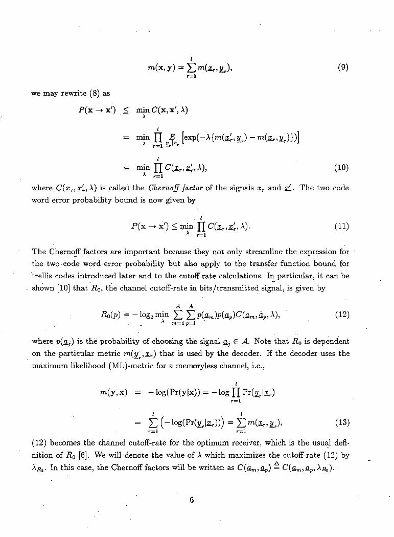
I, y) = £ mUr, £r), (9)
r=l
we may rewrite (8) as
P(x -*• x') < min C(x, x', A)
= min H E [exp(-A{m(x;,yr)-m(xr,£r)})]A -l£rr=l
A r=l
where C(oLr,.£j., A) is called the Chernoff factor of the signals x_r and rj.. The two code
word error probability bound is now given by
lPf-r —» v'\ < min TT C(r T' \\ f 1 1 ~\± I A. f A. J _^ 1I11II I I L/1 X.J., .£ r , A . 11J.I
A r=l
The Chernoff factors are important because they not only streamline the expression for
the two code word error probability but also apply to the transfer function bound for
trellis codes introduced later and to the cutoff rate calculations. In particular, it can be
shown [10] that R0, the channel cutoff-rate in bits/transmitted signal, is given by
^4 ARO(P) = -Iog2min £ £p(am)p(ap)C(am, ap, A), ". (12)
A m=l p=l -
where p(a.j) is the probability of choosing the signal QJ G A. Note that RQ is dependent
on the particular metric m(y ,x.r) that is used by the decoder. If the decoder uses the
maximum likelihood (ML)-metric for a memoryless channel, i.e.,
im(y, x) = - log(Pr(y|x)) = - log [J Pr(yjxr)
I(T 11 \ n "\\H£r>yj> (U)r=l r=l
(12) becomes the channel cutoff-rate for the optimum receiver, which is the usual defi-
nition of RQ [6]. We will denote the value of A which maximizes the cutoff-rate (12) by
. In this case, the Chernoff factors will be written as C(am, ap) = C(am, ap, A/?,,).

2.2 Fading Channel with Side Information
In this section we calculate the Chernoff factors under the assumption that the decoder isfurnished with perfect side information, i.e., at each symbol interval r the fading depth br
is known. We choose our decoding metric as m(t/r, br,x.r) — \y_T ~ &r3Lr|2> which would be
the maximum likelihood metric on an AWGN-channel if the transmitter sent the signalbrx_r during time interval r. Indeed, the decoder will not know whether the transmittermodulated the signal amplitude by multiplying it by the constant br or whether thechannel distorted the symbols in that way. Due to the additional stochastic process &,the two code word error probability becomes
P(x -* x') = E [ J5 [Pr{m(x', b, y) - m(x, b, y) < 0}]] , (14)
where b = (61,..., 6;) is the sequence of fading depths. The above probability can beexpressed in terms of the Chernoff factors, i.e.,
P(x -+ x') < min <7(x, x', A) = min EA A **
£J ~E [exp-(-A (|yr - b^ - \yr - b rx r\ '-1 r
.r=l
The product inside the expectation is minimized by setting A =Chernoff factors become independent of A, i.e.,
. (15)J
= l/(2./Vo) and the
P(X^X') <
r=l
and
E exp (17)
Due to the interleaving the fading depths br are governed by independent identicallydistributed probability distributions and the subscript r on 6 in the above equation can
be dropped. Then we have
7 •

= f exP ("^v"^1""^ (18)
where p(6) *s *ne Rayleigh-Rician probability distribution given in (2). After some ma-
nipulations (18) becomes
(19)
Figure 3 shows R0 from (12) for the Rayleigh (K = 0) fading channel with side
information for several two dimensional signal constellations. In this case, RQ is 3-6dB
smaller than on the AWGN channel [6], [10], but the relative performance of each signal
constellation is preserved. It is worth noting from (5) that if diversity signaling is used
with binary symbols on a Rayleigh fading channel, there is a loss of 5.25dB in SNR
compared to the AWGN-channel with the same noise power spectral density NQ, at the
expense of considerable bandwidth expansion. The RQ- curves" for the fading channel on
the other hand assure that good error performance (i.e., comparable error probabilities to
the AWGN-channel), without the bandwidth expansion introduced by diversity signaling,
is possible, albeit at higher values of the SNR
2.3 _ Fading Channel Without Side Information
With no information on the fading depth available, the decoder uses the maximum like-
lihood metric for the AWGN-channel, i.e., m(a;r,?/ ) = \y_ — s.r|2, and we obtain for the
Chernoff bound
P(x-^x') < minC'(x,x',A) = min£X A b Lr=l2r
[exp(-A(|yr - z;|2 - \y_r - x
- ^2) - 2A6r(aLr2 - xrx'r) + \2NQ(xr - x'r)
2) , (20)
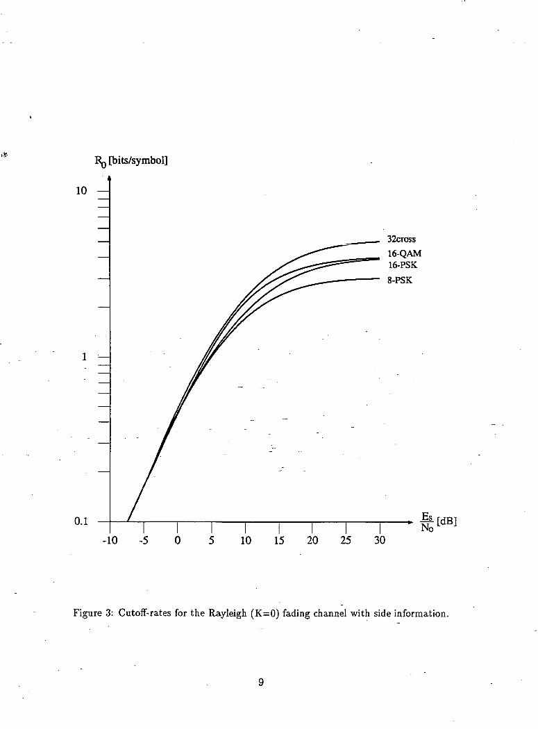
RQ [bits/symbol]
i10 —
0.1
32cross
16-QAM16-PSK
8-PSK
-10 -5 0 5 10 15 20 25 30
Figure 3: Cutoff-rates for the Rayleigh (K=0) fading channel with side information.

which gives us the following expression for the Chernoff factors for the fading channel
without side information,
, xr, A) = e * l * - * H * < * r - * > - ™ < * - * * ) . (21)41 J
can be evaluated as follows:
e , ,_ ,- . _ ~-^ (22)
where
~ cos(^) (23)
and erfc($) = 2/^/v /J° e"7 cfy is the complementary error function. (22) must be evalu-
ated numerically and substituted into (21) to yield the expression for the Chernoff factors
of a Rayleigh/Rician fading channel with no side information available at the receiver. If
we consider the limiting case of a Rayleigh channel with K — 0, the expectation in (22)
can be evaluated in closed form to give
(24)
The ChernofF factors in (21) can then be used in (12) to calculate the cutoff-rate RQ for the
fading channel with no side information. Figure 4 shows RQ curves for the fading channel
without side information for several signal constellations. It is worth noting that, unlike
the case of the AWGN-channel and the fading channel with side information, constant
envelope schemes fare considerably better than rectangular constellations for the fading
channel without side information. The reason for this superiority of constant envelope
schemes is the fact that fading radially shrinks or expands the decision region boundaries.
Because the decoder does not know the fading depth 6T, it cannot adjust these boundaries.
In the case of constant envelope signal constellations, the decision boundaries are radially
symmetric and therefore independent of the fading depth [6, chapter 5].
10
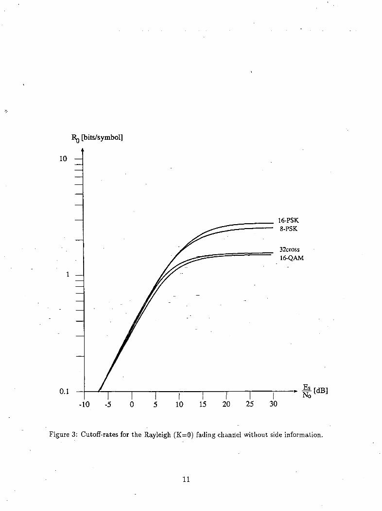
Rg [bits/symbol]
j
10 —
0.1
16-PSK8-PSK
32cross16-QAM
-10 -5 0 5 10 15 20 25 30
Figure 3: Cutoff-rates for the Rayleigh (K=0) fading channel without side information.
11

3 Coding Schemes
3.1 8-PSK Trellis Codes
A rate R = k/n trellis code is generated by a binary convolutions! encoder followed by a
mapper as discussed in section 2. Figure 5 shows a rate 2/3 convolutional encoder and a
mapping to 8-PSK signals without parallel transitions, i.e., k = k. The trellis codes for
fading channels discussed in this paper are based on systematic convolutional codes of
rate 2/3. The output bits of the binary encoder are mapped into the set of 8-PSK signals.
This coded system transmits 2 bits/modulation signal, maintaining the same data rate
as uncoded QPSK modulation.
Mapper
o o oo o o o o • o .o •
o o o o
o "" o o o o oo o o
o " o o oo o o o o o o
"o oo o o
o
o o o
o o o
(000) (001) (010) (Oil) • (100) (101) (110) (111)
Figure 5: Rate 2/3 convolutional encoder with mapping from the binary output triplesinto 8-PSK signals.
Using the delay operator Z), we may express the binary input sequences UQ, u\ ,u\ , . . .
and WQ, «i, «2, • • • as polynomials in £>, i.e., ul(D) = UQ + u\D + u\D2 + • • • and u2(D) =
u^-\-u\D-\-u\D'2-\ ---- . Similarly, the encoder connections may be expressed as polynomials
in D such that H°(D) = H° + H°D + ... + H°D", H\D] = H] + H\D + ... + HlD"f
12

and H\D) = H% + H\D + ... + H^D", where v is the encoder memory and Hg = 1. The
encoding operation can then be expressed in matrix notation as
H\D}/H\D} 1H\D)/H°(D) \ ' ^
where u°(Z?), vl(D\ and v\D) are the polynomials of the three binary output sequences
entering the mapper and 72 is the 2x2 identity matrix.
We will usually give the encoder polynomials H°(D], Hl(D), and fl"2(Z?) in octal
form, i.e., the code H°(D) = 23 (10011), -ff1^) = 04(00100), H\D] = 16(01110) means
H°(D) = D4 + D + I, H\D} = D*, and H\D} =
3.2 Transfer Function Bound
In this section we develop the transfer function bound on the performance of trellis codes
over fading channels. This will lead to a design criterion for good codes. Although the
bit error probability PI, is the quantity of ultimate interest, a closely related and more
readily determined quantity, the event error probability Pe, will be used to characterize
the performance of trellis codes.
If x and x' are two symbol sequences corresponding to two paths through the trellis
which are distinct for / branches starting at node j, and the decoder chooses the encoded
sequence x' over the correct sequence x, this is called an error event of length / starting
at node j. An error event starts where the two paths diverge and ends where the two
paths remerge. A union bound on Pe for a trellis code may be obtained by summing the
probabilities of the error events of all possible lengths given a particular correct sequence
x and averaging this quantity over all possible correct sequences x. -
With each incorrect path we may associate a sequence of incorrect trellis states 5^,
while the sequence of correct states is denoted ST. Any error event of length / can then
be described by / state pairs, (5o, 5o),.. -, (5;,5/), with So = S'0, Si = S'h and Sr ^ S'rfor 0 < r < /, i.e., the incorrect path must not touch the correct path during the error
event. Associated with these paths are the two symbol sequences x = (XQ,^, ... ,Xj) and
x' = (x^, x.i,... ,£/), where x.r,x^. 6 A. The probability of an error event may be upper
bounded using the Chernoff factors (with A = A/^) between the individual signals of the
two code sequences which the paths generate. We may therefore write
13

(26)r=l
We now introduce the transfer function matrix T as the 22" x 22" matrix whose rows
and columns are labeled with state pairs (5r, S'r) a^d whose elements at the intersection
of row (5,-, Sj) and column (Sk, Si} are given by
tij,ki — \ if the transition 5,- —» Sfc (27)or Sj —> S't does not exist,
where rr,-jt is the signal the encoder transmits when it changes from state 5,- to S/, and x.'jtis the signal on the trellis branch connecting state 5j to 5,'. tij,ki represents the ChernofF
factors averaged over a pair of branches corresponding to the state pairs (Si, Sk) and
(S'j, S'i). Note that the sum over x.^ is over all parallel transitions leading from state Sj to
state 5;, the sum over £.ik is over all parallel transitions that lead the encoder form state
5,- to Sk, and m = 2h~k is the number of parallel transitions. The factor 1/ro reflects
the fact that one of these transitions is selected with probability 1/m by the transmitter
following the correct path.
Rearranging the state pairs in the matrix T, we can write
(28)TIC Tn
where C is the set of state pairs such that Sr = S'r, called a correct state pair, and / is the
set of state pairs such that Sr ^ S'T, called an incorrect state pair. The 2" x 2" submatrix
TCC then contains all branch pairs in the trellis that diverge from a particular state
and immediately remerge again, i.e., all the parallel transitions. TCI and TIC represent
diverging and remerging branch pairs, respectively, while TH represents all branch pairs
that do not touch at either end. All error events start in a correct state pair and return
to a correct state pair. An error event may thus occur in two distinct ways:
• One step error events consist of immediate transitions from one correct state pair
to another. These are the parallel transitions in the trellis and are given by the
submatrix TCC-
14

Error events extending over more than one branch axe given by state pair sequences
starting in the subset C and returning to it via one or more visits to the subset /,
i.e., in matrix notation,
+ Tc/T//T/c + TciTfjTic + •••
or TCi\l + Tn + T}I + ...]TIc (29)
or Tci[I-Tn}-lTrc,
where I denotes the (22" - 2") x (22" - 2") identity matrix. The event error probability
may now be upper bounded by the transfer function bound, i.e.,
Pe < 1T [Tec + TCI [I - TV,]'1 TIC] 1, (30)
where 1. is the 2"-dimensional all-one vector. The post multiplication by 1 represents the
union of the error events from one state to any other state, while the premultiplication
by 1T sums all 2" starting states, each one of which is assumed to have probability 1/2".
Equation (30) can be written in the following form:
tPt, " (31)
where the sum is over all code sequence pairs x, x' whose two codeword error probability
has a specific value of the Chernoff bound Pt = YllT=iC(x_r,x^.) and At is the average
number of code sequence pairs with Chernoff bound Pt-
3.3 Effective Length
In order to gain insight into the problem, we will approximate the expression in (30). In
the submatrix TCC, one term will usually be dominant. This is the nearest neighbor to
the correct path among all the parallel transitions. Let this dominant term be PC, i.e.,
Pc = C(xr,xlr\ (32)
where the signal pair x.r,^. is the one with the smallest value of the Chernoff factor.
Similarly, the second term inside the bracket of (30) will have a" dominant term, which
15

we denote by P/. This is an error event of length / > 1, that extends over more than one
branch. According to (26), PI can be written as
(33)
We now look at two particular cases, the additive white Gaussian noise channel andthe Rayleigh fading channel with side information. For the Gaussian channel
PC = C(xr,£) = e-^T- = e-^o, (34)
where the dominant signal pair (x.r, x^.) is the one with the smallest value of (a^ — a^.)2,i.e., the one with the smallest squared Euclidean distance, denoted by A2. Similarly P/may be evaluated as
P j — T \ C ( r r'\ — e'tN^^r^Zr-^rf — P~^ (^}fl — J.J. ^\2Ln3Lr) — e ° — e°, ^<->;r=l
where the dominant path pair is the one with the smallest cumulative squared Euclideandistance, denoted by d2, the minimum free squared Euclidean distance of the code. Inthe Gaussian case it is unimportant over how many branches this minimum free squaredEuclidean distance is accumulated, i.e., the right hand side of (35) is independent of /.
For the Rayleigh fading channel with K = 0, we obtain the following expression forP C from (19): - . . - - . _ - '
T7> (36)
where the approximation is tight for ES/NQ > 6dB, which is usually the case for trans-mission over a fading channel. Hence in the Rayleigh fading case the dominant termfor parallel transitions is also the one with the smallest squared Euclidean distance A2
between two signals. P/ on the other hand may be evaluated as
r=l
(37)( '
16

where /' equals I, the length of the path pair, less the number of matches, i.e., the numberof branches where x.T = £. We call /' the effective length of the path pair and l'm = min(/')
the effective length of the code, where the minimum is taken over all path pairs. Theapproximation is again tight for Es/N0 > QdB. Equation (37) is dominated by the pathswith the shortest effective length, i.e., /' = l'm, and among those by the one having thesmallest product in the denominator, i.e., the one with the smallest squared product
distance <Pp = n'r=i (s.r — &)2- Hence the total event error probability in the fading case3Lr*3!r
can be approximated by
(38),
where ki is the average number of parallel transitions with the smallest squared Euclideandistance A2 and &2 is the average number of trellis path pairs with the smallest squaredproduct distance <i2. It is clear from (38) that parallel transitions are most harmful in theRayleigh case and should be avoided, unless A2 is considerably larger than d2 and thecode is used at a low SNR Es/NQ. In that case it is questionable if the necessary synchro-nization can be maintained in order to decode any but the most simple constellations. In
Table 1 we list the effective length (l'm) and the minimum squared product distance (d2,),i.e., the smallest squared product distance of those path pairs with /' = ^,.for the set ofrate 2/3 trellis codes designed by Ungerboeck [11], [12] for the AWGN-channel.
i.d.
g2g3g4
Ssg?g8
g9gio
v
2
34567.89
10
H°(D)
511
23451031114351007
2003
ff'M2020416030054072164164
*(D)-
041634
066122130260770
I'm
1' 2
32
34
334
fp
4
84.688162.75161632
Table 1: Ungerboeck's 8-PSK codes.
These codes use an 8-PSK signal set and are among the best codes known for the AWGN-
channel. However they suffer a significant performance degradation on the Rayleigh
17

fading channel due to their small l'm and the slow increase in l'm with code complexity,
which explains their poor performance discussed in section 4.
Table 2 shows a list of 8-PSK codes designed for fading channels, i.e., designed for a
large effective length l'm. The codes were found using either an exhaustive search or one
of the construction methods presented in [13] and [14].
i.d.f2f3f4f5
fBf7f8
£9flOfll
V
234567891011
H°(D)
5112343103223673141333036403
Hl(D)
2020414
036076336756
16763436
«*(D)-
041636154314164244
5041264
fm
12334455
56
448
4.6816
88
5.4918.75
12810.98
Table 2: Codes designed for fading channels.
Note that the codes in Table 2 have, with the exception of the very short codes
f2=g2, f3=g3, and f4=g4, a larger effective length l'm, which should give them superior
performance on fading channels, especially at high values of ES/NQ. The Gaussian codes
designed for a large free squared Euclidean distance d^ achieve this distance over only
a few branches in most cases. This proves detrimental on fading channels, where the
distance should be spread more evenly over all the branches of a trellis path pair.
3.4 Binary Signaling
Due to the synchronization problem, binary signaling is usually used on fading channels.
Let us assume for the sake of discussion that the trellis is generated by a rate R = k/n
binary convolutions! encoder. Instead of the two dimensional multilevel/phase signals x,ron the branches of the trellis in the case of bandwidth efficient coding, n binary signals
are used. These signals are antipodal if coherent reception is possible (BPSK-signaling)
and orthogonal otherwise. We also assume that the binary signals are interleaved to make
the channel memoryless. The ChernofF factor for the two signals x_T and x^ is then given
by
18

.x'ri), (39)
where xr; is the i-th bit on the r-th branch of x and the path error probability bound of
(26) becomes
Pr[(S0, ...,$,)-» (Si, - - - , 5,')] < fl ft C(xH, *',,•) = ft C(zfcl x',), (40)r=l i=l Jk=l
where x* and x'k, I < k < nl, are the two binary signal sequences associated with the
error event (So, S'0), . . . , (5;, 5|). Substituting the Chernoff factors for binary signals, we
obtain
Pr[(S0,...,S,) -*($£,.. . , S/)] < l
n T-^MT- («)Since (xfe — x^)2 equals 0 or A2, depending on whether x\, = x'k or Xk ^ x'k, we cansimplify (41) to obtain
n/ 4-Nr.
Pr[(S0,...,5/)--(5;....,50]=i ^
where c?(x, x') denotes the Hamming distance between the two binary sequences x andx' that make up the two paths in question. Equation (42) shows that the well known
Hamming distance remains the design criterion for binary signaling on the fading channel.
It is worth noting that a 3dB coding gain may be achieved if phase synchronization is
possible, since the binary signals may then be chosen to be antipodal, i.e., A2 = 4.Es,
where Eg is the signal energy. If phase synchronization is not possible, the signals must
be orthogonal, giving A2 = 2£s, reflecting a 3dB loss. For a more extensive discussion
on binary signaling for the fading channel see [6] and [16].
19

3.5 Rician Fading Channels
The Rayleigh fading channel is the limiting case of a more general channel, the Rician
fading channel. In the Rician case the expression for PC is, from (19),
Pa = CfrM = e — . (43)
on the other hand is given by
r=l r=l
Comparing (43) and (44), it becomes obvious that the performance degradation of the
parallel transitions becomes less and less severe as the energy Ed received on the direct
path increases with respect to the energy Em received via the diffuse multipaths; i.e., with
growing K. Hence for Rician fading channels with strong line of sight reception, paralleltransitions become feasible. For small values of the Rice factor /<", i.e., K < Es/N0, (43)
and (44) can be approximated as . . . .
Pc =
It becomes evident then that for small values of the Rice factor K, the effective length
l'm is once again the dominant code design criterion.
3.6 Distance Spectrum of Fading Channel Codes
Using the approximations (37) or (46) for the Chernoff factors C(zr,x^), the expression
for the transfer function bound (31) can be written in the form
P/V, ' (47)
20

where Ai'^' is the average number of code sequence pairs x, x' with effective length /'and product distance d', P\'^< is the event error probability -bound for an event errorwith effective length V and product distance <£', and the average is taken over all codesequences x in the code. The parameter A\I^I is called the average multiplicity of allcode sequence pairs with event error probability bound Pi'td'- Note that in (47) the errorbound Pi'ji includes both terms of the form (32) (parallel transition error events) and
terms of the form (33) (length / > 1 error events).For fading channels a spectral line is defined by an effective length /', a product
distance d', and an average multiplicity Ay^. The set of all spectral lines of a code is
called the distance spectrum of that code. In [15], we present an algorithm that computes
the distance spectrum for quasi-regular codes, a general class of codes to which ail the bestknown trellis codes belong. This algorithm has been adapted to compute the distancespectrum of codes for fading channels. Figure 6 shows the distance spectrum of the 16-state 8-PSK from Table 2 (code f4), where the factors in the product distances d' havebeen normalized by the square root of the signal energy v/^5- The effective length of thiscode is l'm — 3, its minimum squared product distance is d"^ — 4.68, and its multiplicityis ^3,4.68 = 2. Note that Figure 6 is divided into different diagrams for different effectivelengths /'. The distance spectrum is used in section 4 to evaluate the performance ofcodes on fading channels. " .
3.7 Block Code Performance on a Quantized Fading Channel
In this section we discuss the use of block codes as an alternative to trellis codes onfading channels. The received 2-dimensional signal y_ is mapped into a discrete outputalphabet, as illustrated in Figure 7 for an 8-PSK signal set. For MPSK signaling, eachreceived signal y_ is decoded into one of M angular sections, called decision regions, anddenoted by A,. Because of the high probability of a deep fade, i.e., the reception of asignal with a very low amplitude 6, we have introduced a circular erasure region withradius p. This is done with the idea of using Reed-Solomon block codes which can handleerasures. In conjunction with interleaving, this transforms the fading channel into adiscrete memoryless erasure channel.
Let qij be the conditional probability that the received signal y_ lies in Aj, given that
the signal x.,- was sent, and let qe be the probability that y falls into Ae, i.e.,
21

Multiplicity A,
4 - -
2--
3 6
Multiplicity A4
4 --
2 --
Effective Length=3
9 12 15 18 21 24 27
_^ productdistance
Effective Length=4
3 6 9 12 15 18 21 24 27
6 9 12 15 18 21 24 27
productdistance
Itip
4 -
2-
icity A15,P
|
(8.375)
1 1 ,
(19) .(12)
Effective Length=
I
-
=5
productdistance
Figure 6: Fading distance spectrum of coded 8-PSK modulation (Code f4).
99

= Pr(y |
and
= -±- fTT^VO •'A;
(48)
(49)
Ai\
A
A4
Figure 7: Decision regions for an 8-PSK signal set with an erasure region.
-As an example, we will discuss the performance of an RS(63,42) block code usingthis quantized 8-PSK channel. The symbols of the RS(63,42) block code are 6 bits long,i.e., two concatenated 8-PSK signals. This code has a symbol rate k/n = 42/63, whichtranslates into a bit rate of 2 bits/signal, i.e., the same transmission rate as uncodedQPSK, the reference transmission system. The receiver operates such that if any one ofthe two received vectors y, ,y2 belonging to the same RS-symbol is decoded into Ae, thewhole RS-symbol is erased.
Using the Berlekemp-Massey decoding algorithm, the RS-decoder can correct any
combination of t errors and e erasures as long as e + 2t < n — fc, where n — k is thenumber of parity symbols. For this particular code, the symbol erasure probability PA isgiven by PA = qeqe+2qe(l—qe}, the probability of receiving a correct symbol is P? = $00^00,
and the probability of receiving a symbol, in error is given by P,- = 1 — Pc — PA-
23

The block error probability Pg of such an RS-code may then be computed as
I ff-~fe I
~ t « n-t-e
+ E u 1 tf C1 - p'')n~'- (50)<=LIl7iJ+l ^ '
Figure 8 compares the performance of this bandwidth efficient RS-block code to uncodedQPSK. The erasure threshold radius p has been optimized for each value of Es/NQ.
4 Comparison of Code Performance
In this section we present performance curves on the event error probability Pe of severalTCM schemes. The 8-PSK trellis codes introduced in Section 3 are quasi-regular 3, and
we have used a variant of the algorithm reported in [15] to evaluate Pe. The two codeword error probability bound in (10) is given by
' P(x -> x') < minC(x,x', A) = min fl C(xr, x'r, A), (51)A A r=l
where the tightest bound is obtained by individually minimizing (51) over A for each pathpair x, x'. In view of the large number of code sequence pairs x, x', this is computationallyunfeasible. However, any value of A may be used in (51) to obtain a looser bound. Wechoose A = A;^, i.e., the value of A which maximizes J?o, and the two code word boundof (51) becomes equivalent to the terms Pt in the event error probability bound of (31),
i.e.,/
P <• \^ A p -nr^arp P TT ftr T' \ ^9^•* e _ 2 — i ^ t ' 1 wnere Xj — j^ u(>x.r,xTj. \^^)t r=l
The algorithm in [15] is a stack type algorithm which successively searches code se-quence pairs in increasing order of a metric associated with those code sequence pairs.This metric is additive over the individual signal pairs in the code sequences, and in [15]
it is the squared Euclidean distance between those signal pairs. For A = A^, if we write
3For a precise definition of quasi-regularity, the reader is referred to [15].
24
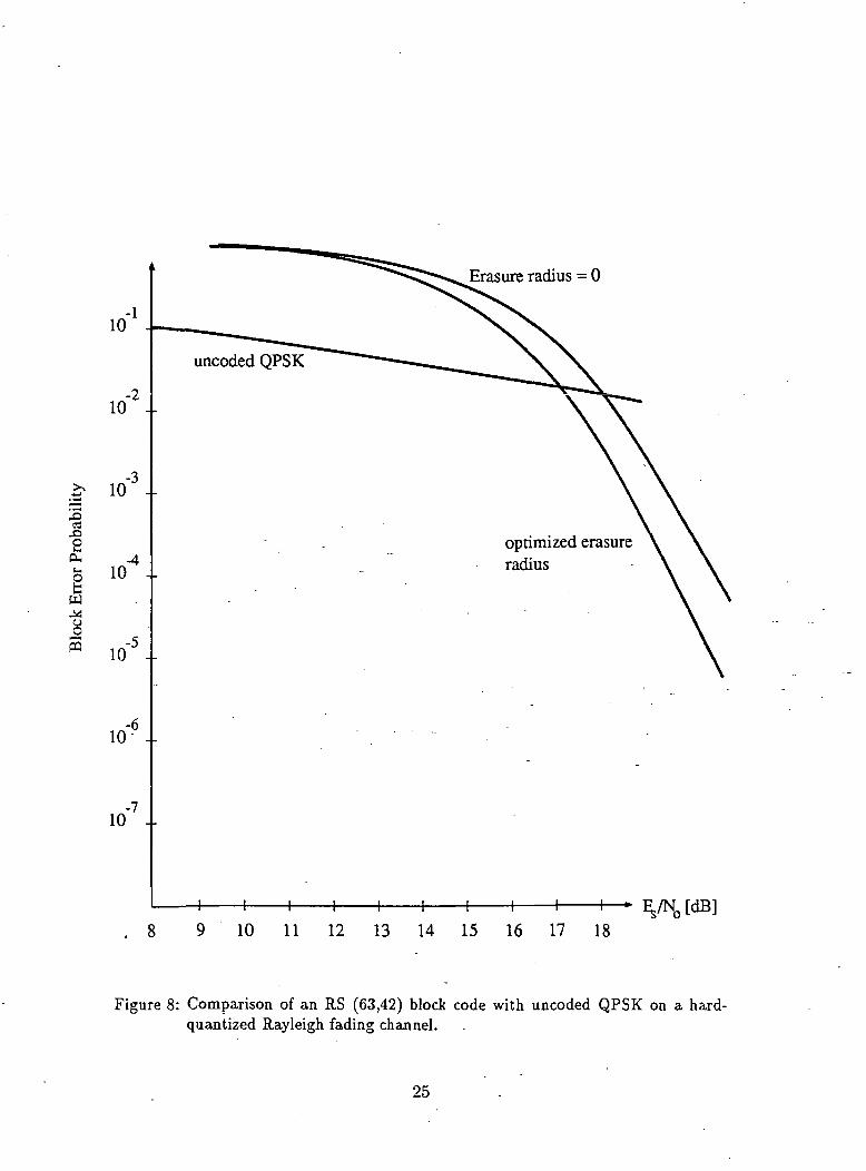
Erasure radius = 0
cd£>eCUI_
g
w
ffl
uncoded QPSK
optimized erasureradius
I 1 1 1 1 1 1 1—- E./NJdB].8 9 10 11 12 13 14 15 16 17 18
Figure 8: Comparison of an RS (63,42) block code with uncoded QPSK on a hard-quantized Rayleigh fading channel.
25

(53)r=l
and choose — lnC(ir,^) as the branch metric, the algorithm can be used in a slightlyaltered form to calculate the event error probability of any quasi-regular TCM scheme.
In general, Pt = Yl'r=l C(x.T,x^) will depend on Es/NQ as well as on the specific signalsx_r and x!r, 1 < r < /, and we must run the algorithm separately for each value of the SNR.
If, however, the Chernoff factors are accurately approximated by (37) or (46), where theydepend only on Es/N0, /', and d! (fading channels with side information), the distancespectrum can be used to evaluate Pe for all values of ES/NQ and the algorithm is usedonly once per code to calculate the distance spectrum. In this case the distance spectrumgives a good measure of code performance. As shown in the following figures codes with agood dis-tance spectrum usually also perform well on channels where the approximations(37) or (46) may not be tight (fading channels with no side information, Rician channels
with a large Rice factor).Figures 9 to 13 show the event error probability bound of some selected codes, where
we have used (53) to evaluate Pe. Figure 9 shows the performance on a Ray lei gh channelwith side information. The superiority of the new codes presented in Table 2 is evident.At an error probability level of Pe = 10~5, for example, the code fS shows a 3.5dBimprovement over the code g8. At Pe = 10~6, the difference is 4.5dB. Note further thatthe asymptotic behavior of the Gaussian codes g8 and g6 are identical and it is thereforeuseless to employ the higher complexity of code g8.
Figure 10 shows the same set of codes on a Rician channel with K = IdB, a typicalvalue of the Rice factor. Again the fading codes from Table 2 outperform the Gaussiancodes form Table 1 of the same complexity. The code f8, for example, achieves -an errorprobability of Pe = 10~6 at an Es/No of 12.2dB, while the code g8 achieves the sameerror performance at l3.7dB. At Pe = 10~7, the gain of f8 over g8 is 2.5dB.
Figure 11 shows the same set of codes on a K = !5dB Rician channel. This value ofK indicates strong line of sight reception. In this environment, the Gaussian codes fare
slightly better due to their superior minimum free squared Euclidean distance. fS and g8have almost identical error performance, while f6 loses l.2dB compared to g6.
Figures 12 and 13 show the same set of codes on a-Rayleigh fading channel and a Rician
channel with K = IdB and without side information. . While the relative performance• of the codes with respect to each other is preserved, the lack of side information causes
26

a rather severe degradation in performance, particularly for the Rayleigh channel. At
an error probability of Pe = 10~5, for instance, f8 gains 3dB over g8 on the Rayleigh
channel and gains IdB on the K = IdB Rician channel. It is fortunate that for the
Rayleigh channel side information can be extracted relatively easily from the receiver by
monitoring a pilot tone, or in the case of constant envelope signaling by simply estimating
the received signal amplitude.
Comparing the performance of the RS-block code to TCM, we see that the RS-code isvery poor for Es/N0 < 20dB. The error curves for the RS-code have a rather sharp cutoff
and catch up with the trellis codes at an Es/N0 of about ZOdB for the Rayleigh channelwith side information. With no side information, the RS-code performance curve crossesthe f8 performance curve at Es/Nn « 25dB. This behavior is typical when comparingthe performance of block codes and trellis codes.
5 Conclusions
We have presented a general method of bounding the event error probability of TCMschemes and applied this method to the fading channel. We have shown that the effectivelength and the minimum squared product distance replace the minimum free squaredEuclidean distance as a design criterion for Rayleigh fading channels and Rician fadingchannels with a substantial multipath component. We have presented codes specificallyconstructed for fading channels that outperform equivalent codes designed for the AWGN-channel. -The use of RS-block codes with expanded signal sets becomes interesting onlyfor large SNR's, where they begin to outperform trellis codes.
6 Acknowledgement
We wish to acknowledge the help of Mr. Marc Rouanne in preparing the program usedto compute the distance spectrum of the codes presented in this paper.
27

2? 10 ...
eaJO2
.c 10
.4
f8
H 1 1 1
8 9 10 11 12 13 14 15 16 17 18
Figure 9: Performance of trellis codes on a Rayleigh channel with side information.
28

8 9 10 11 12 13 14 15 16 17 18
Figure 10: Performance of codes on a Rician channel with K = IdB and with sideinformation.
29

.OS3
IS 10 -><U
W
Iw
10 11 12 13 14 15 16 17 18[dB]
Figure 11: Performance of trellis codes on a Rician channel with K = l5dB and withside information.
30

io'2i
* io'3i
c 10 -I-D
W
f8
8 9 10 11 12 . 13 14 15 16 17 18
Figure 12: Performance of trellis codes on a Rayleigh channel with no side information.
31
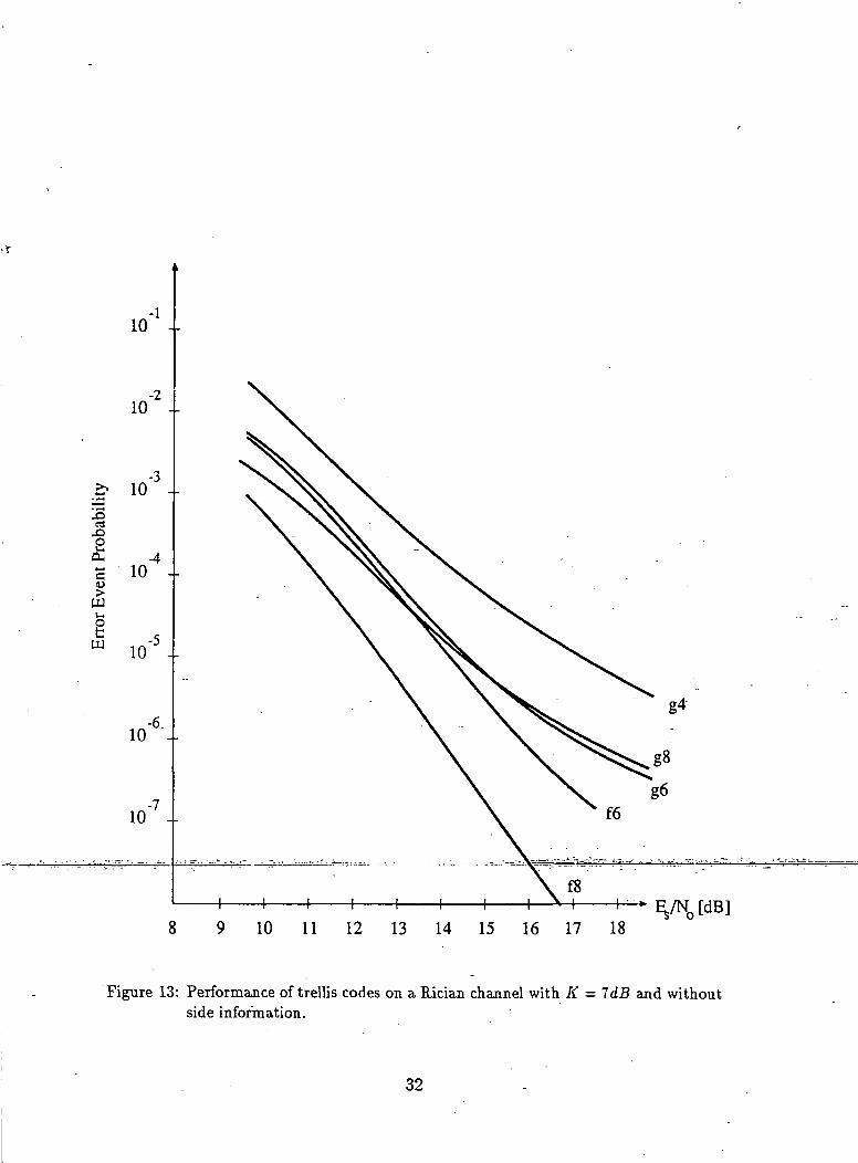
8 9 10 11 12 13 14 15 16 17 18
Figure 13: Performance of trellis codes on a Rician channel with K = 7dB and withoutside information.
32

References
[1] A. Ghais et. al., "INMARSAT and the Future of Mobile Satellite Services", IEEE
Journal Selected Areas Commun., Vol. SAC-5, No.4, May 1987, pp. 592-600.
[2] J. Hagenauer et al., "The Maritime Satellite Communication Channel," IEEE
Journal Selected Areas Commun., Vol. SAC-5, No.4, 701-713, May 1987.
[3] J. Hagenauer and E. Lutz, "Forward Error Correction Coding for Fading Com-
pensation in Mobile Satellite Channels," IEEE Journal Selected Areas Commun.,
Vol. SAC-5, No.2, pp. 215-225, February 1987.
[4] M. K. Simon and D. Divsalar, "The Performance of Trellis Coded Multilevel
DPSK on a Fading Mobile Satellite Channel", presented at the IEEE 1987 Inter-
national Conference on Communications, Seattle, WA, June 7-10, 1987.
[5] M. K. Simon and D. Divsalar, "Trellis Coded Modulation for 4800-9600 bits/s
Transmission Over a Fading Mobile Satellite Channel," IEEE Journal Selected
Areas Commun., Vol. SAC-5, No.2, pp. 162-177, February 1987.
[6] J. M. Wozencraft and I. M. Jacobs, Principles of Communication Engineering,
New York, Wiley, 1965.
[7] R. G. Gallager, Information Theory and Reliable Communications, New York,
Wiley, 1968. . • - . . -
[8] R. S. Kennedy, Fading Dispersive Communication Channels, New York, Wiley,
1969. -
[9] D. Divsalar and M. K. Simon, "The Design of Trellis Codes for Fading Channels",
submitted for publication.
[10] C. Schlegel, "Bandwidth Efficient Coding for Non-Gaussian Channels", Ph. D.
Dissertation, University of Notre Dame, Notre Dame, Indiana, 1988.
[11] G. Ungerboeck, "Channel Coding with Multilevel/Phase Signals," IEEE Trans.
Inform. Theory, Vol. IT-28, No.l, pp. 55-67, January, 1982..
33

[12] G. Ungerboeck, "Trellis-Coded Modulation with Redundant Signal Sets Part II:State of the Art," IEEE Communications Magazine, Vol. 25, No.2, pp. 12-21,February, 1987.
[13] J. E. Porath and T. Aulin, "Fast Algorithmic Construction of Mostly OptimalTrellis Codes" Technical Report No. 5, Division of Information Theory, ChalmersUniversity of Technology, Goteborg, Sweden, February 1987.
[14] M. Rouanne, "Distance Bounds and Construction Algorithms for Trellis Codes",Ph. D. Dissertation, University of Notre Dame, Notre Dame, Indiana, 1988.
Cl5l M, P.ouanne, D= J= Costello, Jr* and C> Schle«rel- "An Algorithm for Comrvu.tin°' theDistance Spectrum of Trellis Codes", Proceedings 1988 Conference on InformationSciences and Systems, Princeton, New Jersey, March 16-18, 1988.
[16] I. M. Jacobs, "Probability-of-Error Bounds for Binary Transmission on the SlowlyFading Rician Channel", IEEE Trans. Inform. Theory, Vol. IT-12, No.4, October1966, pp. 431-441.
34