electra irp use cases simulations - erigrid.eu · designing and validating the future, intelligent,...
TRANSCRIPT

Designing and validating the future, intelligent, electric power systems
Kassel, Sept. 6th 2017
Julia Merino Fernández
ELECTRA IRP Use Cases
Simulations
www.ElectraIRP.eu
The research leading to these results has
received funding from the European Union
Seventh Framework Programme (FP7/2007-
2013) under grant agreement n° 609687

2 ELECTRA IRP on Smart Grids
Designing and validating the future, intelligent, electric power systems– Sept 6th 2017, Kassel
Overview
• PPVC
• Adaptive FCC
• BRC+FCC = DLFC
• IRPC vs. Fast FCC
Fundamentals Setup Simulation
results

3 ELECTRA IRP on Smart Grids
Designing and validating the future, intelligent, electric power systems– Sept 6th 2017, Kassel
PPVC

4 ELECTRA IRP on Smart Grids
Designing and validating the future, intelligent, electric power systems– Sept 6th 2017, Kassel
PPVC Fundamentals
Two operation modes Planning phase: Proactive
Real-time operation: Corrective
Proactive Proactive Corrective

5 ELECTRA IRP on Smart Grids
Designing and validating the future, intelligent, electric power systems– Sept 6th 2017, Kassel
A PPVC single-cell test setup
European CIGRÉ MV grid benchmark (modified with DERs)
• Two feeders
• DERs
• 8 PV plants
• 2 batteries
• 2 fuel cells
• 2 CHPs
• 1 Wind Turbine
Load, PV pannels DERs patterns adjusted to match the grid requirements and
dynamic controls have been modeled
Note: Implementation in PowerFactory software
PV panels generation forecast
PQ load forecast

6 ELECTRA IRP on Smart Grids
Designing and validating the future, intelligent, electric power systems– Sept 6th 2017, Kassel
PPVC Results (I)
A) Planning phase (‘Proactive’ mode)
Optimal voltage set-point are calculated for the next 15-min windows in 1-min intervals
Why optimal power flows in a “Planning phase”?
The advantages of the WoC…
• Full observability
• Advanced communication technologies (less communication efforts)
• Increase in the calculation speed and data storage managment capabilities
Non-optimized planned voltage in t є (t’A+1 – t’A+2)
(current practice)
Optimized planned voltage in t є (t’A+1 – t’A+2)
(WoC proposed practice)
Total P losses = 0.0483 MW
Total Q losses = 0.4778 MVAr
Total P losses = 0.0462 MW (-4,3574%)
Total Q losses = 0.4645 MVAr (-2.7914%)
Voltage control optimization
in a single step

7 ELECTRA IRP on Smart Grids
Designing and validating the future, intelligent, electric power systems– Sept 6th 2017, Kassel
PPVC results (II)
B) Real-time operation (‘Corrective’ mode)
An unexpected event occurs during the
real-time cell operation (tA’) and the
previous calculated pattern (in the
proactive mode) needs to be recalculated
En t=tA’, U_NODE12<lower
limit_safe band
Real node voltages
Optimal set-points before/after the event

8 ELECTRA IRP on Smart Grids
Designing and validating the future, intelligent, electric power systems– Sept 6th 2017, Kassel
PPVC results (III)
B) Proactive vs. Corrective’mode
9 ELECTRA IRP on Smart Grids
Designing and validating the future, intelligent, electric power systems– Sept 6th 2017, Kassel
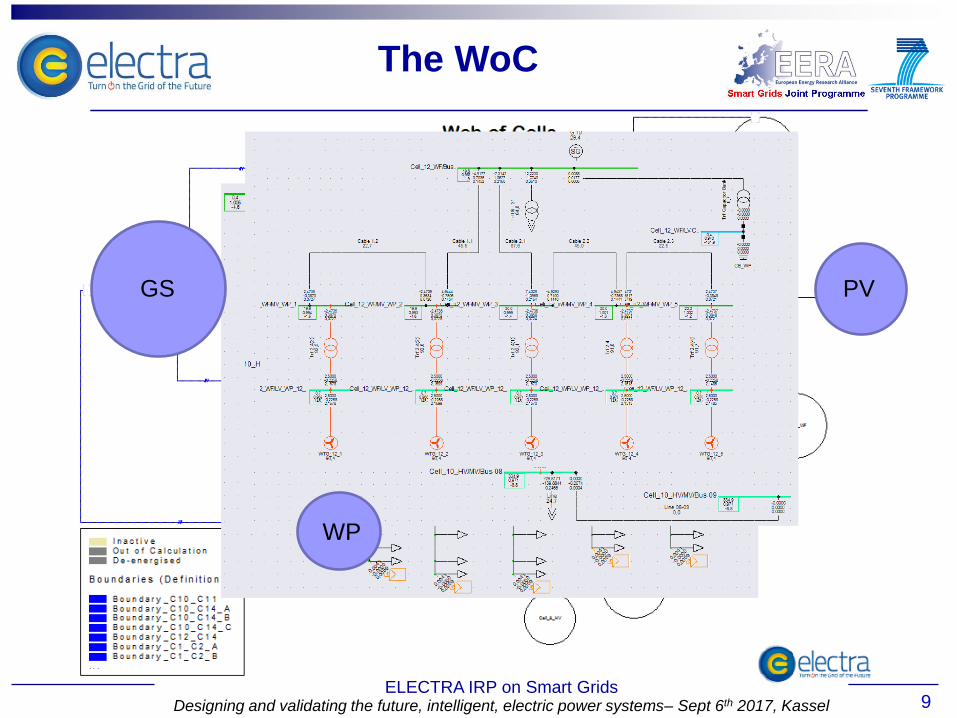
PV GS
The WoC
WP

10 ELECTRA IRP on Smart Grids
Designing and validating the future, intelligent, electric power systems– Sept 6th 2017, Kassel
Adaptative FCC

11 ELECTRA IRP on Smart Grids
Designing and validating the future, intelligent, electric power systems– Sept 6th 2017, Kassel
Adaptive FCC fundamentals
• Frequency Droop responsibility explicitly delegated to
cells
• Optimal decomposition of the cell’s CPFC (contribution
to NPFC) over the available resources adding a droop
scaling factor that depends on the state of the cells
− Avoid that FCC activations cause imbalances
− Responsibilization

12 ELECTRA IRP on Smart Grids
Designing and validating the future, intelligent, electric power systems– Sept 6th 2017, Kassel
Test assumptions
• CIGRE MV reference grid
• 1HV and 3MV cells
• Two adaptive controllers in cells 1
and 2
• Only the HV cell was equipped
with frequency restoration
process
Δfi
ΔPtie,i NH NL ZE PL PH
NH 0% 33% 100% 100% 100%
NL 33% 66% 100% 100% 100%
ZE 66% 100% 100% 100% 66%
PL 100% 100% 100% 66% 33%
PH 100% 100% 100% 33% 0%
Test Grid setup
Rule table
A-FCC test setup

13 ELECTRA IRP on Smart Grids
Designing and validating the future, intelligent, electric power systems– Sept 6th 2017, Kassel
Short-term performance (200s) 3MW increase in Node 02
Long-term performance (24-hour tests) Small droop of 1MW/Hz in the HV cell / Load step reductions every 15 min
Overall use of reserves
Reduction is use of renewables
𝐴𝐵𝑆 = ∆𝑃𝑑𝑟𝑜𝑜𝑝,1 +⋯+ ∆𝑃𝑑𝑟𝑜𝑜𝑝,𝑛 𝑑𝑡∞
0
𝐶𝑜𝑠𝑡 = ∆𝑃𝑑𝑟𝑜𝑜𝑝,12+⋯+ ∆𝑃𝑑𝑟𝑜𝑜𝑝,𝑛
2𝑑𝑡
∞
0
Function With Adaptive FCC With Fixed Droop ABS
(Reduction) 8.59e+7(Ws)
-19.7% 1.07e+8(Ws)
Cost 6.94e+12(W2s) 9.46e+12(W2s) (Reduction) -26.7%
RES With Adaptive FCC With Fixed Droop WG
(Reduction) 1.24e+7(Ws)
-18.0% 1.51e+7(Ws)
PVs 8.97e+6(Ws) 9.56e+6(Ws) (Reduction) -6.2%
A-FCC test results
Max. Freq F-FCC = 52.54 Hz
M. Freq. A-FCC = 52.50 Hz
Min. Freq F-FCC = 49.51 Hz
M. Freq. A-FCC = 49.42 Hz

14 ELECTRA IRP on Smart Grids
Designing and validating the future, intelligent, electric power systems– Sept 6th 2017, Kassel
FCC+BRC = DLFC

15 ELECTRA IRP on Smart Grids
Designing and validating the future, intelligent, electric power systems– Sept 6th 2017, Kassel
DTLC Fundamentals
Currently employed AGCs use PI controllers
• Rigid tuning, susceptible to parameter variations
• Non-linearities (ramp rates, delays) problematic, only working points can be optimally tuned
Proposed LFC
• Supported by the Web-of-Cells (WoC) capabilities: high degree of observability and comm.
• Two-staged control
Power matching through direct observations
Primary reference frequency control to balance unobserved powers and inaccurate measurements
• Tuning-free, adaptive, handles variable droops
• Stable over a wide range of parameters, agnostic to actuator non-linearities
WoC’s “keep local problems local”
• Secondary response decoupled from the system response
• Primary resources actively involved in frequency control
• Frequency is treated as a local quantity ← Inferred over primary resources’ states

16
AGC vs. DLFC

17
Scenario Parameter Cell 1 Cell 2 Cell 3
High J J [kg·m²] 20 20 0.2
H [s] 4.1 10.25 0.24
P_pri_ramp [kW/s] 2 5 0
T_sec_delay [s] 5 2.5 1
Low J J[kg·m²] 2 0.2 0.2
2 H [s] 0.41 0.1 0.16
P_pri_ramp[kW/s] 25 15 0
T_sec_delay [s] 0.1 0.1 0.1
Controller Parameter Cell 1 Cell 2 Cell 3
AGC T_ctrl [s] 1 1 1
KP [1] 0.065 0.09 0.1
KI [1/s] 0.08 0.11 0.13
BRC T_ctrl [s] 1 1 1
omega_f 1/3 1/3 1/3
omega_P 1/3 1/3 1/3
All load events (observed and
unobserved) are 5 kW
DTLC simulation results

18 ELECTRA IRP on Smart Grids
Designing and validating the future, intelligent, electric power systems– Sept 6th 2017, Kassel
DTLC conclusions
The DLFC shows satisfying performance
• AGC only performing better in working points it was tuned against
• Non-linearities are handled very well, stability was proven on paper and in real
experiments
• Frequency control works also under partial observability
DLFC fits well into the BRC/WoC context
• Supports adaptive droop (FCC)
• Benefits from fast secondary response (BRC variant)
Known shortcomings
• Good knowledge of controlled devices’ droop capability
needed (but AGC needs it for the whole area)
• Can only balance tielines in case of total observability
• → Tieline imbalance observer needed

19 ELECTRA IRP on Smart Grids
Designing and validating the future, intelligent, electric power systems– Sept 6th 2017, Kassel
IRPC vs. Fast FCC
IRPC+FCC Overview

20 ELECTRA IRP on Smart Grids
Designing and validating the future, intelligent, electric power systems– Sept 6th 2017, Kassel
IRPC vs. FCC Overview
This study aims at evaluating the capability of frequency
containment control (FCC) and Inertia response control
(IRPC) in mitigating the RoCoF as well as the two controllers
effects on the frequency performance.
The study is divided into two parts:
• Simulations study in DIgSILENT PowerFactory
• Experimental validation in SYSLAB (PowerLab DK)

21 ELECTRA IRP on Smart Grids
Designing and validating the future, intelligent, electric power systems– Sept 6th 2017, Kassel
IRPC vs. FCC setup

22
Measurement delay
(100ms)
Device delay
(10ms, 50ms, 100ms, 250ms)
RoCoF calculation and
Measurement delay (100ms)
Device delay
(10ms, 50ms, 100ms, 250ms)
2% droop
IRPC vs. FCC Controllers

23 ELECTRA IRP on Smart Grids
Designing and validating the future, intelligent, electric power systems– Sept 6th 2017, Kassel
IRPC vs. FCC results
EVs are used as flexibility
resources
Applied droops
Frequency standard deviation
for the two controllers
Different granularity from EVs
(i.e. EVs’ charging current are
modulated with 1A granularity)
Variation of Load steps
IRPC 2 kW load event

24
Can Fast frequency containment control compensate or replace the
need for Inertia response control?
• This work analytically showed the interdependence between frequency
containment and synthetic inertia control on the transient frequency
variation and the RoCoF
• On the simulation level, it presented the ability of fast frequency control in
improving the frequency in terms of nadir, steady state value and RoCoF. It
also presented the ability of synthetic inertia control (IRPC) to improve the
frequency nadir and slope following an event.
• Finally, an experimental validation was conducted, presenting the
capabilities and limitations of the two controllers under two different
circumstances: following load events in both directions and exogenous
wind generation profiles

25
CONTACT
INFORMATION
ELECTRA IRP on Smart Grids Event details – date and Place
Julia Merino Fernández, Ph.D.
ELECTRA IRP website Link: www.ElectraIRP.eu