electra elite ipk ii voip reference manual - document … elite ipk ii voip reference manual i _____...
TRANSCRIPT

Notice
Note that when converting this document from its original format to a .pdf file, some minor font and format changes may occur. When viewing and printing this document, we cannot guarantee that your specific PC or printer will support all of the fonts or graphics. Therefore, when you view the document, fonts may be substituted and your individual printer may not have the capability to print the document correctly.


VOIP REFERENCE MANUAL
INT-2015 (IPK II)DOCUMENT REVISION 1


NEC Unified Solutions, Inc. reserves the right to change the specifications, functions, or features atany time without notice.
NEC Unified Solutions, Inc. has prepared this document for use by its employees and customers. Theinformation contained herein is the property of NEC Unified Solutions, Inc. and shall not be reproducedwithout prior written approval of NEC Unified Solutions, Inc.
Dterm is a registered trademark of NEC Corporation and Electra Elite is a registered trademark of NECAmerica, Inc. Windows is a registered trademark of Microsoft Corporation. AT&T is a registeredtrademark of American Telephone and Telegraph Company. Lucent Technologies is a trademark orservice mark of Lucent Technologies Inc. Nortel Networks and the Nortel Networks logo aretrademarks of Nortel Networks.
Copyright 2006
NEC Infrontia, Inc.6535 N. State Highway 161
Irving, TX 75039-2402
Technology Development

Electra Elite IPK II VoIP Reference Manual i
___________________________________________________________________________________
___________________________________________________________________________________
TABLE OF CONTENTS
Chapter 1 IntroductionSection 1 Electra Elite IPK II IP ............................................................................ 1-1
Section 2 Voice Over IP ..................................................................................... 1-1
Chapter 2 General IP ConfigurationSection 1 Introduction .......................................................................................... 2-1
Section 2 Network Addressing Overview .......................................................... 2-1
2.1 IP Address ...................................................................................... 2-1
2.2 Subnet Mask ................................................................................... 2-2
2.3 DHCP .............................................................................................. 2-2
Section 3 Configuration Examples .................................................................... 2-3
3.1 Example Configuration 1 - Existing Network with Static Addressing ............................................................................ 2-3
3.2 Example Configuration 2 - New Network with Dynamic Addressing ....................................................................... 2-5
Section 4 Testing the Electra Elite IPK II Network Connection ....................... 2-9
Chapter 3 IP ExtensionsSection 1 Introduction .......................................................................................... 3-1
Section 2 IP to TDM Conversion ........................................................................ 3-2
2.1 IP Telephones (ITH) ....................................................................... 3-2
2.2 Electra Elite IPK Multiline Telephone (DTH) with IP Adapter .......... 3-3
Section 3 Power Fail Adapter ............................................................................ 3-3
3.1 Connecting to an IP Telephone ...................................................... 3-4
___________________________________________________________________________________
ii Table of Contents
___________________________________________________________________________________
Document Revision 1 Electra Elite IPK II
3.2 Operation During Power Failure ..................................................... 3-5
Section 4 LAN Connection ................................................................................. 3-6
Section 5 Providing Power ............................................................................... 3-7
5.1 Local Power ................................................................................... 3-7
5.2 Powered Patch Panel ..................................................................... 3-7
5.3 Power Over Ethernet (PoE) ........................................................... 3-7
Section 6 DIP Switch Settings .......................................................................... 3-8
Section 7 Peer-to-Peer ....................................................................................... 3-9
Section 8 Programming ..................................................................................... 3-9
8.1 System Tones and Ring Tones ................................................... 3-10
8.2 Music on Hold .............................................................................. 3-10
Section 9 Configuration Examples ................................................................ 3-10
9.1 Example Configuration 1 - Static IP Addressing, One LAN .......... 3-11
9.2 Example Configuration 2 - Dynamic IP Addressing, One LAN ..... 3-12
Section 10 Example Configuration 3 - Static IP Addressing, Routed WAN . 3-13
Section 11 IP Phone Programming Interface .................................................. 3-14
Section 12 DHCP Server Configuration ........................................................... 3-16
12.1 DHCP Server Configuration Example ........................................... 3-16
Section 13 Configuring Quality of Service ...................................................... 3-20
13.1 Layer 2 Priority Control ................................................................. 3-20
13.1.1 Programming Layer 2 Priority Control ............................... 3-20
13.2 Layer 3 (ToS) Priority Control ...................................................... 3-21
13.2.1 Programming Layer 3 Priority Control ............................... 3-21
Section 14 IP Telephone Registration and Deletion ....................................... 3-22
Section 15 System IP Phones and Analog Trunks ......................................... 3-23
Section 16 Firmware Upgrade Procedure ....................................................... 3-23
Electra Elite IPK II Document Revision 1
Electra Elite IPK II VoIP Reference Manual iii
___________________________________________________________________________________
___________________________________________________________________________________
16.1 Manually Upgrading Firmware ...................................................... 3-24
16.2 Checking the Firmware Version .................................................... 3-24
16.3 Upgrading Automatically ............................................................... 3-24
Chapter 4 IP NetworkingSection 1 Introduction .......................................................................................... 4-1
Section 2 IPK II CCISoIP Network ..................................................................... 4-1
Section 3 IP Trunks ............................................................................................. 4-2
3.1 Configure IP Trunks ....................................................................... 4-2
Section 4 Example Configurations ................................................................... 4-3
4.1 Network Configurations ................................................................... 4-3
4.2 Electra Elite IPK II CCIS over IP Programming Example 1 ............ 4-4
4.2.1 Digital Trunk Assignments ...................................................4-5
4.2.2 VoIP Address Assignments ..................................................4-6
4.2.3 CCIS Availability ...................................................................4-6
4.2.4 IP CCISoIP Assignment .......................................................4-7
4.2.5 CCIS Assignment .................................................................4-7
4.2.6 Centralized Day Night Switching Assignments ....................4-8
4.2.7 Centralized BLF Assignments ..............................................4-8
4.2.8 Local Numbering Plan Assignment ......................................4-9
4.2.9 Closed Numbering Plan - using Closed Number Blocks ....4-10
4.2.10 Tandem Connections .........................................................4-11
Section 5 DTMF Relay ....................................................................................... 4-11
Section 6 VoIP ETU Firmware Upgrade Procedure ........................................ 4-11
Chapter 5 ProgrammingSection 1 Before You Start Programming ......................................................... 5-1
___________________________________________________________________________________
iv Table of Contents
___________________________________________________________________________________
Document Revision 1 Electra Elite IPK II
Section 2 How to Enter Programming Mode .................................................... 5-2
Section 3 How to Exit Programming Mode ...................................................... 5-3
Section 4 Using Keys to Move Around in the Programs ................................ 5-3
Section 5 Programming Names and Text Messages ....................................... 5-5
Section 6 Using Softkeys For Programming .................................................... 5-6
Section 7 What the Softkey Display Prompts Mean ........................................ 5-6
Program 10 : System Configuration Setup ............................................. 5-7
10-03 : ETU Setup ................................................................................. 5-7
10-04 : Music On Hold Setup ............................................................. 5-15
10-12 : CPUII Network Setup .............................................................. 5-16
10-13 : In-DHCP Server Setup ............................................................ 5-18
10-14 : Managed Network Setup ......................................................... 5-19
10-15 : Client Information Setup .......................................................... 5-20
10-16 : Option Information Setup ........................................................ 5-21
10-19 : VoIP ETU DSP Resource Selection ........................................ 5-22
15-05 : IP Telephone Terminal Basic Data Setup ............................... 5-23
84-03 : IP Phone Information Basic Setup .......................................... 5-25
84-05 : VoIP IP Address ...................................................................... 5-26
84-06 : VoIP Info .................................................................................. 5-28
84-09 : VLAN Setup ............................................................................. 5-30
84-10 : ToS Setup ............................................................................... 5-31
84-11 : Dterm IP CODEC Information Basic Setup .............................. 5-33
90-23 : Deleting Registration of IP Telephones ................................... 5-35
90-34 : Firmware Information ............................................................. 5-36
Chapter 6 Network Design ConsiderationsSection 1 Introduction ........................................................................................ 6-1
Section 2 QoS .................................................................................................... 6-1
2.1 QoS Definitions ............................................................................... 6-1
Electra Elite IPK II Document Revision 1
Electra Elite IPK II VoIP Reference Manual v
___________________________________________________________________________________
___________________________________________________________________________________
2.2 Voice Quality Improvements ........................................................... 6-3
2.3 Types of Classifications for Traffic for QoS ..................................... 6-4
Section 3 Internet Based Connections (xDSL, Cable, etc.) ............................ 6-6
Section 4 Firewalls and NAT ............................................................................. 6-7
4.1 Understanding the Infrastructure .................................................... 6-7
4.2 Firewall Integration ......................................................................... 6-8
4.3 Virtual Private Network (VPN) Tunnelling ...................................... 6-9
Section 5 CODEC and Bandwidth ................................................................... 6-12
5.1 CODECs ....................................................................................... 6-12
5.2 Bandwidth ..................................................................................... 6-13
Section 6 DSP Resource Calculation ............................................................. 6-14
Section 7 Quality of Service (QoS) Implementation ....................................... 6-15
7.1 Prioritization .................................................................................. 6-15
7.2 Layer 2 QoS (802.1pq) ................................................................. 6-18
7.3 Layer 3 QoS .................................................................................. 6-22
7.4 IP Precedence .............................................................................. 6-24
7.5 Diffserv (Differentiated Service) .................................................... 6-25
7.6 Comparison of IP Precedence and Diffserv Values ...................... 6-26
7.7 Programming QoS in the Electra Elite IPK II System ................... 6-29
7.7.1 Marking Voice Traffic - Program 84-10-XX ....................... 6-29
7.7.2 IPK II Voice Protocols ........................................................6-29
7.7.3 Configuring Diffserv ............................................................6-30
7.7.4 Configurations for Classification and Queuing - Examples ...........................................................................6-31
84-10 : ToS Setup ................................................................................6-33
Chapter 7 TroubleshootingSection 1 Introduction .......................................................................................... 7-1
___________________________________________________________________________________
vi Table of Contents
___________________________________________________________________________________
Document Revision 1 Electra Elite IPK II
Section 2 Ping ..................................................................................................... 7-1
2.1 Pinging from a PC .......................................................................... 7-3
2.2 Pinging from an Electra Elite IPK II IP Phone ................................. 7-3
Section 3 Packet Traces ..................................................................................... 7-5
Chapter 8 SIP TrunkingSection 1 VoIP ...................................................................................................... 8-1
Section 2 IP Networking ..................................................................................... 8-1
Section 3 SIP Trunking ....................................................................................... 8-2
3.1 Introduction ..................................................................................... 8-2
3.1.1 SIP Trunking Requirements ................................................ 8-3
3.1.2 Programming Conditions ..................................................... 8-3
3.1.3 SIP Trunking Setup .............................................................. 8-4
Section 4 SIP Trunk Overview ........................................................................... 8-4
4.1 General Information ........................................................................ 8-5
4.2 Supported Protocols ....................................................................... 8-5
4.3 Supported SIP Methods ................................................................. 8-5
4.4 Supported SIP Trunking Options .................................................... 8-6
4.5 Supported CODEC ......................................................................... 8-6
Section 5 Supported SIP Trunking Functions ................................................. 8-7
5.1 Address Resolution ........................................................................ 8-7
5.2 Authentication Process ................................................................... 8-7
5.3 Caller ID .......................................................................................... 8-7
5.4 Carrier Support ............................................................................... 8-8
5.5 Early Media ..................................................................................... 8-8
5.6 Fault Tolerance ............................................................................... 8-8
5.7 Network Address Port Translation (NAPT) ..................................... 8-8
5.8 Quality of Service (QoS) ................................................................. 8-8
Electra Elite IPK II Document Revision 1
Electra Elite IPK II VoIP Reference Manual vii
___________________________________________________________________________________
___________________________________________________________________________________
5.9 Registration ..................................................................................... 8-9
5.9.1 Registration Process ........................................................... 8-9
5.9.2 Registration Recover Process ..............................................8-9
Section 6 SIP Trunk Programming .................................................................... 8-9
6.1 SIP Trunk Basic Setup .................................................................... 8-9
6.2 IP DSP Resource .......................................................................... 8-11
6.3 SIP Authentication Information ..................................................... 8-11
6.4 SIP Caller ID ................................................................................. 8-11
6.5 SIP CODEC Trunk ........................................................................ 8-12
6.6 SIP DNS Setup ............................................................................. 8-14
6.7 SIP NAPT Router Setup ............................................................... 8-15
6.8 SIP System Interconnection Setup ............................................... 8-15
6.9 SIP Protocol .................................................................................. 8-15
6.10 SIP Server Information Setup ....................................................... 8-16
6.11 SIP Registrar Setup ...................................................................... 8-17
6.12 SIP Server Status ......................................................................... 8-17
6.13 SIP Trunk Registration Information Setup .................................... 8-18
6.14 SIP UPnP ...................................................................................... 8-18
Section 7 SIP Trunk Flowchart ......................................................................... 8-18
Section 8 SIP Packet Sequence ....................................................................... 8-18
Chapter 9 SIP StationSection 1 Introduction .......................................................................................... 9-1
Section 2 Programming ...................................................................................... 9-2
Section 3 SIP Station Flowchart ......................................................................... 9-9
Chapter 10 IP Station (MEGACO) - MG16Section 1 Introduction ........................................................................................ 10-1
___________________________________________________________________________________
viii Table of Contents
___________________________________________________________________________________
Document Revision 1 Electra Elite IPK II
1.1 Feature Conditions ....................................................................... 10-4
1.2 System Availability ........................................................................ 10-4
1.2.1 Terminals .......................................................................... 10-4
1.2.2 Required Component(s) ..................................................... 10-4
1.3 Required Software ........................................................................ 10-5
Section 2 Programming ................................................................................... 10-5
2.1 VoIP Settings ................................................................................ 10-5
2.2 VOIP ToS Setup ........................................................................... 10-7
2.3 Firmware Download Setup ........................................................... 10-7
2.4 IP Phone Configuration ................................................................ 10-8
2.4.1 IP Telephone Terminal Basic Data Setup ......................... 10-8
2.4.2 IP Phone Information Basic Setup ..................................... 10-9
2.4.3 IP Extension Numbering .................................................... 10-9
2.4.4 IP Phone CODEC Information Basic Setup ....................... 10-9
Section 3 IP Station (MEGACO) MG 16 Operation ....................................... 10-12
3.1 Example Configuration 1 - Static IP Addressing, One LAN ........ 10-12
3.2 Example Configuration 2 - Dynamic IP Addressing, One LAN ... 10-13
3.3 Example Configuration 3 - Static IP Addressing, Routed LAN ... 10-14
Section 4 Flow Chart ...................................................................................... 10-18
Chapter 11 PVA Combo CardSection 1 Introduction ....................................................................................... 11-1
Section 2 System Requirements ..................................................................... 11-2
2.1 Required Components .................................................................. 11-2
2.2 Stations, Trunks and Terminals .................................................... 11-2
2.3 PVA Combo Card Service Conditions .......................................... 11-3
Section 3 Logical Port Number Assignments ................................................ 11-5
Section 4 Digital Signal Processing (DSP) Resource Handling ................... 11-8

Electra Elite IPK II Document Revision 1
Electra Elite IPK II VoIP Reference Manual ix
___________________________________________________________________________________
___________________________________________________________________________________
Section 5 Programming .................................................................................... 11-8
5.1 VoIP Settings ................................................................................ 11-8
5.2 VOIP ToS Setup ......................................................................... 11-10
5.3 VoIP Logical Trunk Assignment .................................................. 11-10
5.4 VoIP DSP Resource Selection .................................................... 11-11
Chapter 12 Glossary

___________________________________________________________________________________
x Table of Contents
___________________________________________________________________________________
Document Revision 1 Electra Elite IPK II
THIS PAGE INTENTIONALLY LEFT BLANK

Electra Elite IPK II VoIP Reference Manual xi
___________________________________________________________________________________
___________________________________________________________________________________
LIST OF FIGURES
Figure 2-1 Example Configuration 1 - Existing Network with Static IP Address .............................2-3
Figure 2-2 Example Configuration 1 - Adding the IPK II KSU to the Network ................................2-5
Figure 2-3 Example Configuration 2 - New Network with Dynamic Addressing .............................2-6
Figure 2-4 TCP/IP Properties Screen .............................................................................................2-8
Figure 2-5 Testing the Network Connection ...................................................................................2-9
Figure 3-1 IP (ITH) Telephone ........................................................................................................3-2
Figure 3-2 Electra Elite IPK II Multiline Telephone with IP-R(IPK) Unit ..........................................3-3
Figure 3-3 Power Fail Adapter Connection .....................................................................................3-4
Figure 3-4 IP Telephone Connection ..............................................................................................3-4
Figure 3-5 Typical Network IP Connection .....................................................................................3-6
Figure 3-6 IP-R Unit Adapter DIP Switch Settings ..........................................................................3-8
Figure 3-7 Example Configuration 1 - Static IP Addressing, One LAN .......................................3-11
Figure 3-8 Example Configuration 2 - Dynamic IP Addressing, One LAN ....................................3-12
Figure 3-9 Example Configuration 3 - Static IP Addressing, Routed WAN ..................................3-13
Figure 3-10 DHCP Server Configuration ........................................................................................3-17
Figure 3-11 Option Type Dialog Box ..............................................................................................3-18
Figure 3-12 Scope Options Dialog Box ..........................................................................................3-19
Figure 4-1 Example IP Network Configuration ...............................................................................4-3
Figure 4-2 Programming Example 1 ...............................................................................................4-4
Figure 6-1 Layer 2 Diagram (802.1Q) .............................................................................................6-5
Figure 6-2 Virtual Private Network (VPN) Example ......................................................................6-11
Figure 6-3 Network Bottleneck Example ......................................................................................6-16
Figure 6-4 Voice and Data Network Implementation ....................................................................6-17

___________________________________________________________________________________
xii List of Figures
___________________________________________________________________________________
Document Revision 1 Electra Elite IPK II
Figure 6-5 Priority Queuing on Voice and Data Networks ............................................................ 6-18
Figure 6-6 Protocol Structure for Layer 2 QoS ............................................................................. 6-19
Figure 6-7 Layer 3 QoS Example ................................................................................................. 6-22
Figure 6-8 Common Network with Cisco Router .......................................................................... 6-31
Figure 7-1 Ping Traces ................................................................................................................... 7-2
Figure 7-2 Ping Usage Example ..................................................................................................... 7-4
Figure 7-3 Trace File Example ....................................................................................................... 7-6
Figure 8-1 Common IP Network using Electra Elite IPK II SIP Trunk ............................................ 8-3
Figure 9-1 Example - SIP Phone .................................................................................................... 9-8
Figure 10-1 Example - Static IP Addressing, One LAN ................................................................ 10-12
Figure 10-2 Example - Dynamic IP Addressing, One LAN ........................................................... 10-13
Figure 10-3 Example - Static IP Addressing, Routed WAN .......................................................... 10-14
Figure 10-4 IP Phone Programming ............................................................................................. 10-17
Electra Elite IPK II VoIP Reference Manual xiii
___________________________________________________________________________________
___________________________________________________________________________________
LIST OF TABLES
Table 1-1 VoIP Specifications ..........................................................................................................1-2
Table 3-1 DIP Switch Settings .........................................................................................................3-8
Table 3-2 IP Phone Programming User Menu Options ..................................................................3-14
Table 5-1 Keys for Entering Data .....................................................................................................5-3
Table 5-2 Keys for Entering Names .................................................................................................5-5
Table 5-3 Softkey Display Prompts ..................................................................................................5-6
Table 6-1 CPUII Port Assignments ...................................................................................................6-8
Table 6-2 IP Phone Port Assignments .............................................................................................6-9
Table 6-3 Type of Service Field (IP Precedence - i Ref. REC 1349) .............................................6-24
Table 6-4 Diffserv Parameters ........................................................................................................6-25
Table 6-5 IP Precedence and Diffserv Values Comparison ...........................................................6-27
Table 6-6 VoIP Protocol Traffic Types ............................................................................................6-29
Table 6-7 ToS Modes .....................................................................................................................6-30
Table 6-8 Cisco Router Configuration Example .............................................................................6-32
Table 11-1 SIP Trunk License ..........................................................................................................11-5
Table 11-2 PVA(X)-U ETU License ..................................................................................................11-6
Table 11-3 24-Port License PVA(X)-U( ) ETU with Combo Card Application DSP Resource Configuration Example ...................................................................................11-6
Table 12-1 Glossary of Commonly used Abbreviations and Terms .................................................12-1

___________________________________________________________________________________
xiv List of Tables
___________________________________________________________________________________
Document Revision 1 Electra Elite IPK II
THIS PAGE INTENTIONALLY LEFT BLANK
Electra Elite IPK II VoIP Reference Manual 1 - 1
Intro
du
ctio
n
1Introduction
SECTION 1 ELECTRA ELITE IPK II IP
Electra Elite IPK II Solutions is an enterprise IP Telephony solution. It allows businesses and organizations to converge their voice and data network to secure the many advantages of IP telephony, while enjoying the hundreds of features that they have come to expect from the telephone systems.
SECTION 2 VOICE OVER IP
Voice over IP (VoIP) is a technology that converts speech into data packets and transmits these packets over TCP/IP networks. The technology also facilitates compression and silence suppression to reduce network bandwidth demands.
As most organizations already have existing data networks in place, considerable cost savings can be achieved by utilizing spare bandwidth on these networks for voice traffic.
Electra Elite IPK II supports the use of IP Phones. These telephones provide the same functionality as a multiline telephone but utilizes the data network rather then the traditional telecoms infrastructure. This can reduce costs and allows the use of Electra Elite IPK II telephones in locations that would not normally be supported by multiline telephones.
Electra Elite IPK II can also use VoIP technologies to connect two or more telephone systems together. This can eliminate inter-site call charges, and can also simplify calling between sites (as desk-to-desk dialing is possible).
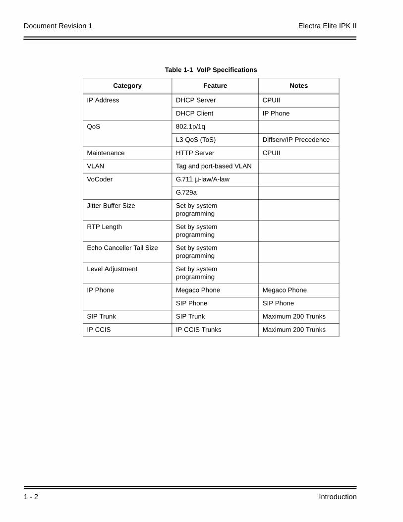
Table 1-1 VoIP Specifications lists the specifications for various aspects of Electra Elite IPIK II VoIP system.
Document Revision 1 Electra Elite IPK II
1 - 2 Introduction
Table 1-1 VoIP Specifications
Category Feature Notes
IP Address DHCP Server CPUII
DHCP Client IP Phone
QoS 802.1p/1q
L3 QoS (ToS) Diffserv/IP Precedence
Maintenance HTTP Server CPUII
VLAN Tag and port-based VLAN
VoCoder G.711 µ-law/A-law
G.729a
Jitter Buffer Size Set by system programming
RTP Length Set by system programming
Echo Canceller Tail Size Set by system programming
Level Adjustment Set by system programming
IP Phone Megaco Phone Megaco Phone
SIP Phone SIP Phone
SIP Trunk SIP Trunk Maximum 200 Trunks
IP CCIS IP CCIS Trunks Maximum 200 Trunks
Electra Elite IPK II VoIP Reference Manual 2 - 1
Ge
ne
ral IP
Co
nfig
uratio
n
2General IP Configuration
SECTION 1 INTRODUCTION
The Electra Elite IPK II system uses IP for various applications, including:
System Programming
Voice Over IP
Switching
This section describes the procedure for connecting the Electra Elite IPK II system to an existing data network and configuring TCP/IP. This is the first step in implementing VoIP and other IP applications.
SECTION 2 NETWORK ADDRESSING OVERVIEW
Before connecting the to a data network, it is necessary to obtain the relevant IP Addressing information. This information will be supplied by the IT Manager or Network Administrator at the customer site.
2.1 IP Address
All equipment/devices used in the LAN setup must have an IP address assignment. An IP address assigns a unique address for each device. There are two types of IP addresses: Private and Global. A Private IP address is not accessible through the internet - a Global IP address can be accessed through the internet.
In most cases, a Private address will be used, as LAN devices are not usually directly connected to the internet. Private addresses are usually taken from the following ranges:
Class A 10.0.0.0 ~ 10.22.255.255
Class B 172.16.0.0. ~ 172.31.255.255
Class C 192.168.0.0 ~ 192.168.255.255
Document Revision 1 Electra Elite IPK II
2 - 2 General IP Configuration
A Public address is normally only used when a device is directly connected to the internet. This is unlikely in the case of the equipment. If Public addressing is used, the numbers are normally allocated by an ISP.
2.2 Subnet Mask
As the IP address includes information to identify both the network and the final destination, the Subnet Mask is used to set apart the network and destination information. The default subnet masks are:
Class A 255.0.0.0
Class B 255.255.0.0
Class C 255.255.255.0
The Subnet Mask is made up of four groups of numbers. When a group contains the number "255", this tells the router to ignore or mask that group of numbers in the IP address as it is defining the network location of the final destination.
For example, if the IP address were: 172.16.0.10 and the Subnet Mask used was Class B (255.255.0.0), the first two groups of numbers (172.16) would be ignored once they reached the proper network location. The next two groups (0.10) would be the final destination within the LAN to which the connection is to be made.
Note that it is possible to have sub-netted networks - in which case the subnet mask may not be the same as those listed above.
2.3 DHCP
DHCP (Dynamic Host Configuration Protocol) is a protocol, which assigns a dynamic IP address. Network control may be easier with DHCP as there is no need to assign and program individual IP addresses for the LAN equipment. To use a dynamic IP address, a DHCP server must be provided. The Electra Elite IPK II system CPUII( )-U( ) ETU provides an internal DCHP server enabling the ability to use DHCP.
When equipment, which is connected to the LAN (the DHCP client), is requesting an IP address, it searches the DHCP server.
When the request for an address is recognized, the DHCP server assigns an IP address, Subnet mask, and the IP address of the router, etc., based upon Electra Elite IPK II system programming.
Note that the CPUII( )-U( ) ETU must always have a static IP address. This address is set in Program 10-12-01 : CPUII Network Setup - IP address (default: 172.16.0.10).
Electra Elite IPK II Document Revision 1
Electra Elite IPK II VoIP Reference Manual 2 - 3
SECTION 3 CONFIGURATION EXAMPLES
The following configuration examples illustrate a typical network configuration for an existing network that uses a static address and a typical configuration for a new network that uses a dynamic address.
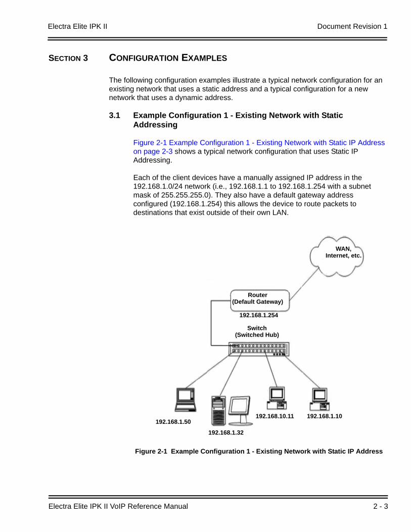
3.1 Example Configuration 1 - Existing Network with Static Addressing
Figure 2-1 Example Configuration 1 - Existing Network with Static IP Address on page 2-3 shows a typical network configuration that uses Static IP Addressing.
Each of the client devices have a manually assigned IP address in the 192.168.1.0/24 network (i.e., 192.168.1.1 to 192.168.1.254 with a subnet mask of 255.255.255.0). They also have a default gateway address configured (192.168.1.254) this allows the device to route packets to destinations that exist outside of their own LAN.
Figure 2-1 Example Configuration 1 - Existing Network with Static IP Address
Router(Default Gateway)
WAN,Internet, etc.
192.168.1.254
192.168.1.50
192.168.1.32
192.168.10.11 192.168.1.10
Switch (Switched Hub)
Document Revision 1 Electra Elite IPK II
2 - 4 General IP Configuration
Assume that an Electra Elite IPK II is added to the existing data network. The Network Administrator (or IT Manager) should provide the following:
IP Address (for the CPUII( )-U( ) ETU)
Subnet Mask
Default Gateway
A spare switch/hub port
First, program the Electra Elite IPK II:
PRG10-12-01: 192.168.1.200
PRG10-12-02: 255.255.255.0
PRG10-12-03: 192.168.1.254
A system reset is required for the IP Address changes to take effect.
Now connect the CPUII( )-U( ) ETU Ethernet Port to the switch/hub port, using a standard Cat-5 patch cable. The Electra Elite IPK II is now configured on the network and should be accessible by other devices on the network. Refer to Figure 2-2 Example Configuration 1 - Adding the IPK II KSU to the Network.
Electra Elite IPK II Document Revision 1
Electra Elite IPK II VoIP Reference Manual 2 - 5
3.2 Example Configuration 2 - New Network with Dynamic Addressing
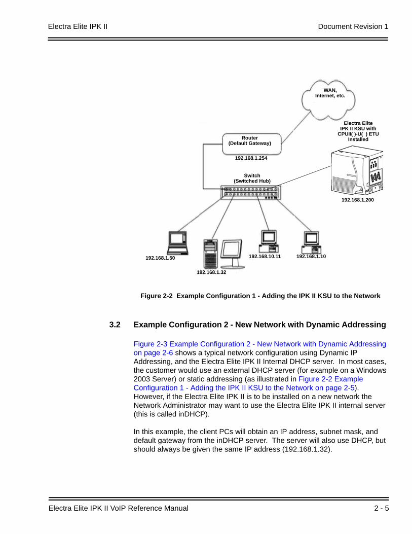
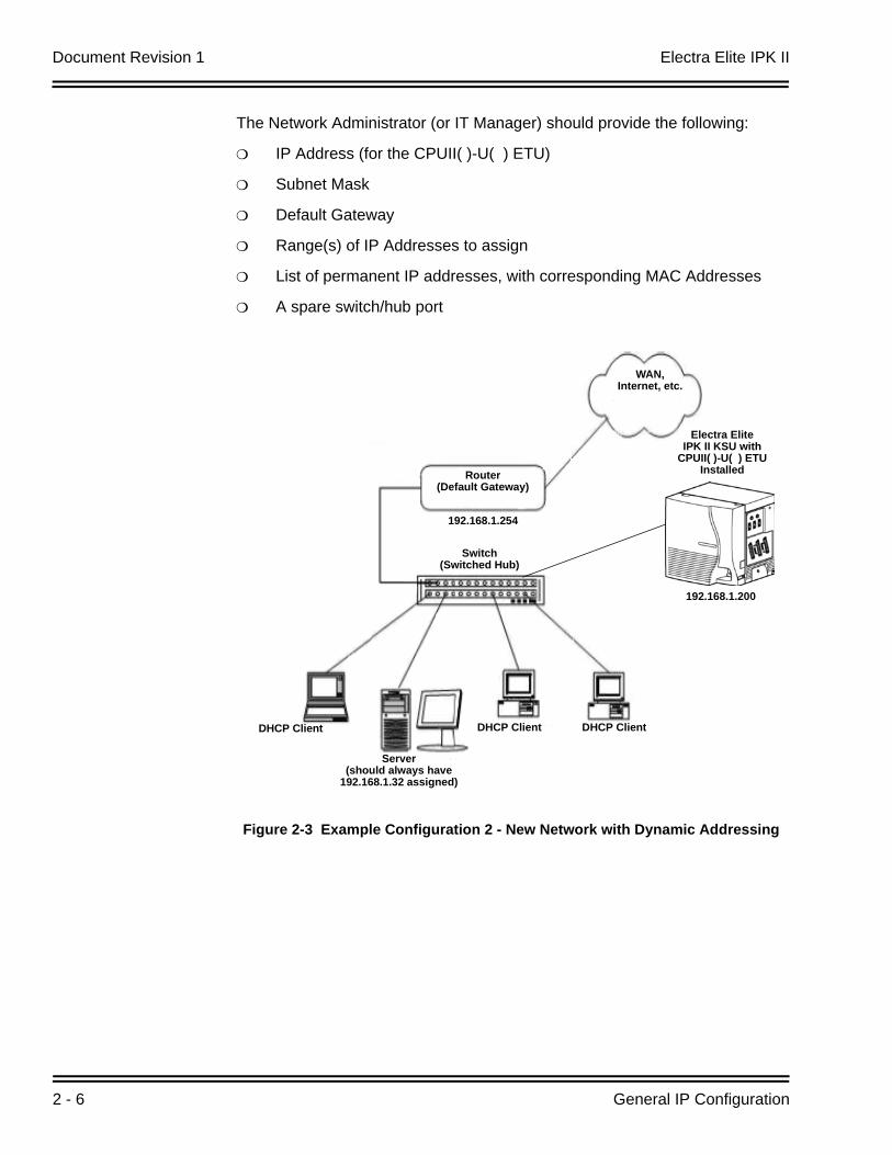
Figure 2-3 Example Configuration 2 - New Network with Dynamic Addressing on page 2-6 shows a typical network configuration using Dynamic IP Addressing, and the Electra Elite IPK II Internal DHCP server. In most cases, the customer would use an external DHCP server (for example on a Windows 2003 Server) or static addressing (as illustrated in Figure 2-2 Example Configuration 1 - Adding the IPK II KSU to the Network on page 2-5). However, if the Electra Elite IPK II is to be installed on a new network the Network Administrator may want to use the Electra Elite IPK II internal server (this is called inDHCP).
In this example, the client PCs will obtain an IP address, subnet mask, and default gateway from the inDHCP server. The server will also use DHCP, but should always be given the same IP address (192.168.1.32).
Figure 2-2 Example Configuration 1 - Adding the IPK II KSU to the Network
Router(Default Gateway)
WAN,Internet, etc.
192.168.1.254
192.168.1.50
192.168.1.32
192.168.10.11 192.168.1.10
Electra Elite IPK II KSU with
CPUII( )-U( ) ETU Installed
192.168.1.200
Switch (Switched Hub)
Document Revision 1 Electra Elite IPK II
2 - 6 General IP Configuration
The Network Administrator (or IT Manager) should provide the following:
IP Address (for the CPUII( )-U( ) ETU)
Subnet Mask
Default Gateway
Range(s) of IP Addresses to assign
List of permanent IP addresses, with corresponding MAC Addresses
A spare switch/hub port
Figure 2-3 Example Configuration 2 - New Network with Dynamic Addressing
Router(Default Gateway)
WAN,Internet, etc.
192.168.1.254
DHCP Client
Server(should always have
192.168.1.32 assigned)
Electra Elite IPK II KSU with
CPUII( )-U( ) ETU Installed
192.168.1.200
DHCP Client DHCP Client
Switch (Switched Hub)
Electra Elite IPK II Document Revision 1
Electra Elite IPK II VoIP Reference Manual 2 - 7
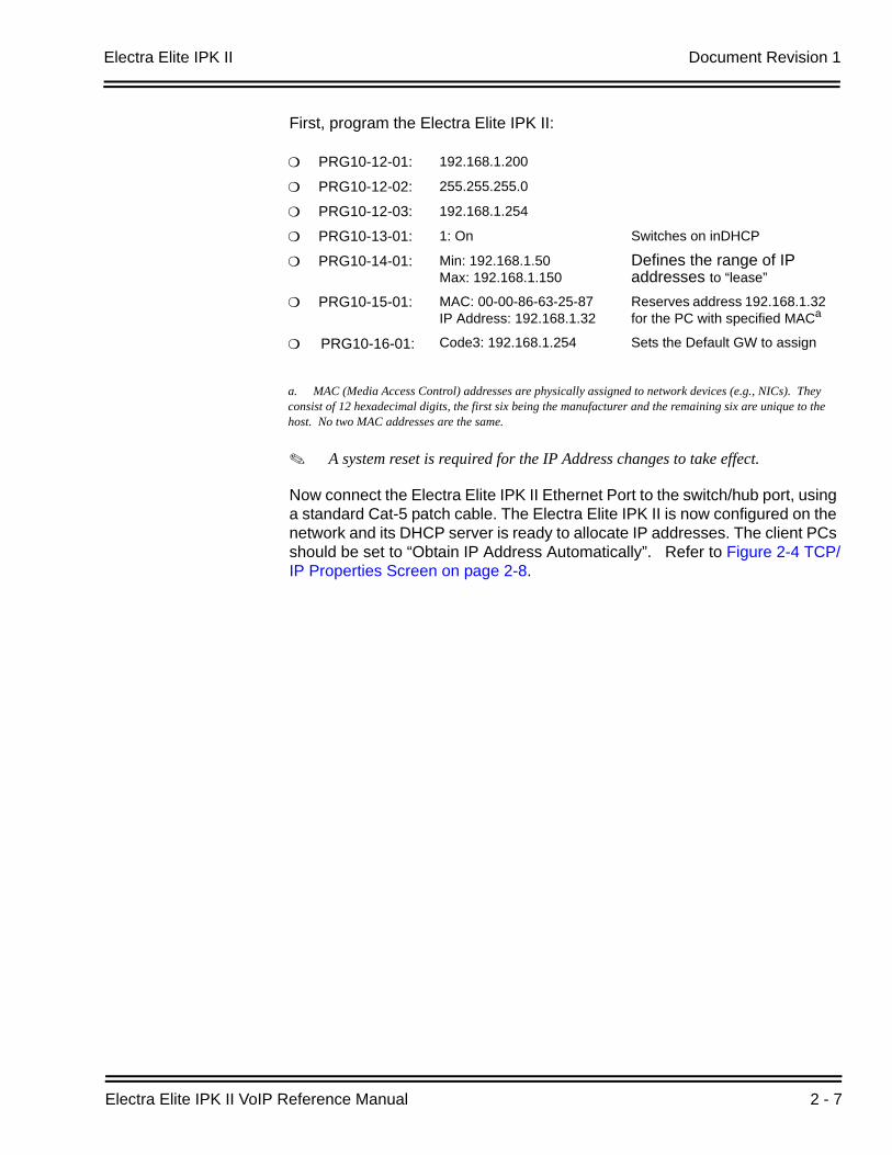
First, program the Electra Elite IPK II:
A system reset is required for the IP Address changes to take effect.
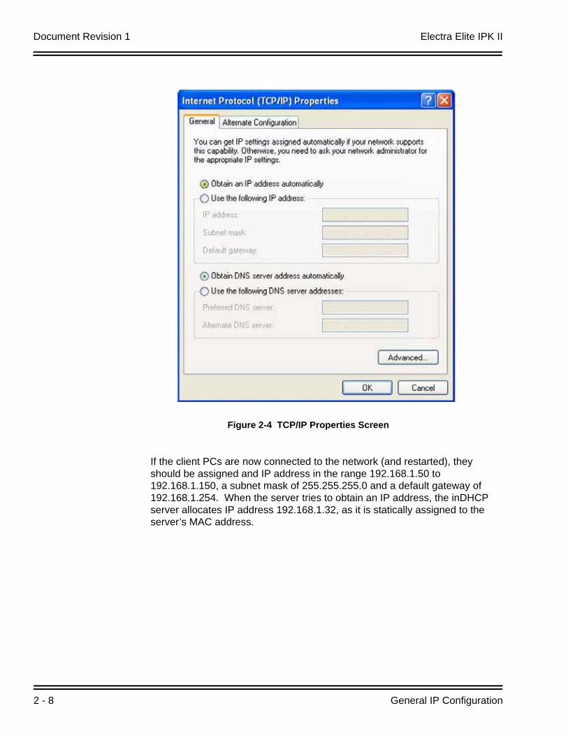
Now connect the Electra Elite IPK II Ethernet Port to the switch/hub port, using a standard Cat-5 patch cable. The Electra Elite IPK II is now configured on the network and its DHCP server is ready to allocate IP addresses. The client PCs should be set to “Obtain IP Address Automatically”. Refer to Figure 2-4 TCP/IP Properties Screen on page 2-8.
PRG10-12-01: 192.168.1.200
PRG10-12-02: 255.255.255.0
PRG10-12-03: 192.168.1.254
PRG10-13-01: 1: On Switches on inDHCP
PRG10-14-01: Min: 192.168.1.50Max: 192.168.1.150
Defines the range of IP addresses to “lease”
PRG10-15-01: MAC: 00-00-86-63-25-87IP Address: 192.168.1.32
Reserves address 192.168.1.32 for the PC with specified MACa
a. MAC (Media Access Control) addresses are physically assigned to network devices (e.g., NICs). They consist of 12 hexadecimal digits, the first six being the manufacturer and the remaining six are unique to the host. No two MAC addresses are the same.
PRG10-16-01: Code3: 192.168.1.254 Sets the Default GW to assign
Document Revision 1 Electra Elite IPK II
2 - 8 General IP Configuration
If the client PCs are now connected to the network (and restarted), they should be assigned and IP address in the range 192.168.1.50 to 192.168.1.150, a subnet mask of 255.255.255.0 and a default gateway of 192.168.1.254. When the server tries to obtain an IP address, the inDHCP server allocates IP address 192.168.1.32, as it is statically assigned to the server’s MAC address.
Figure 2-4 TCP/IP Properties Screen
Electra Elite IPK II Document Revision 1
Electra Elite IPK II VoIP Reference Manual 2 - 9
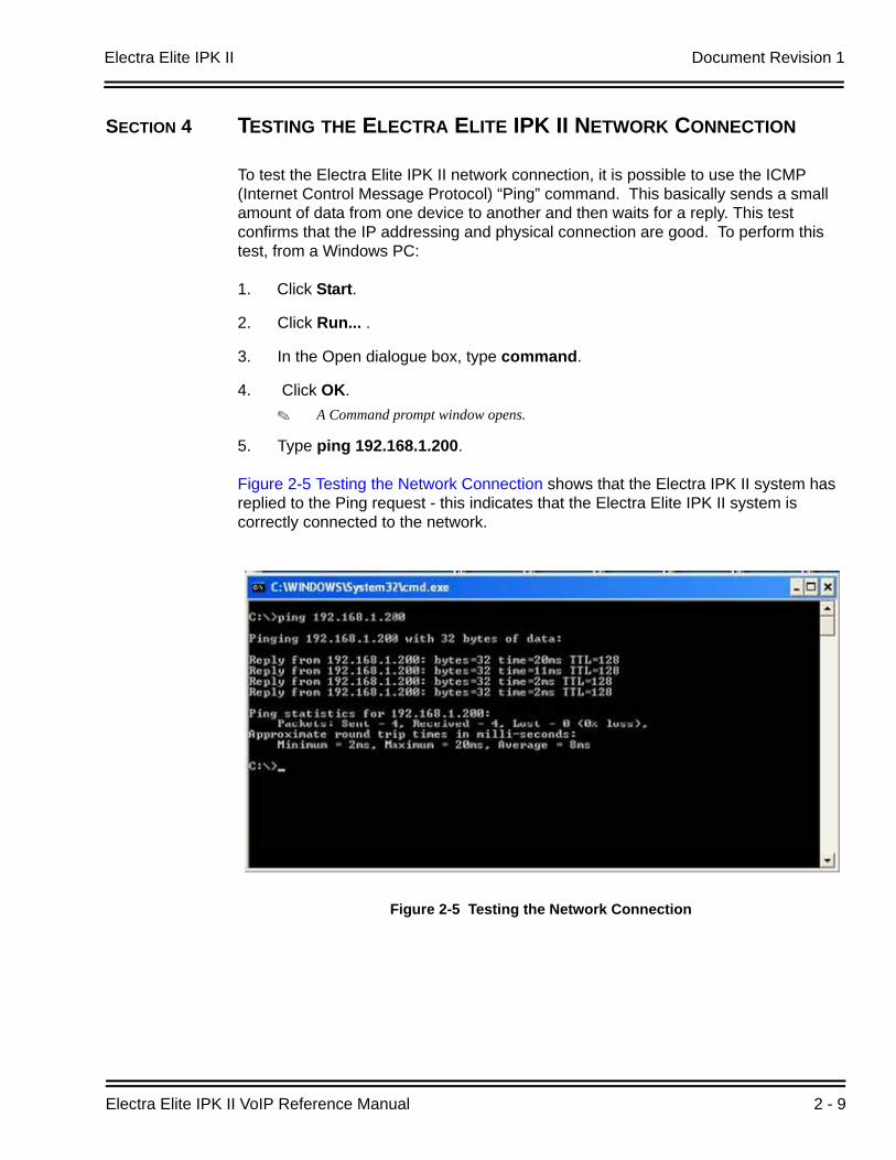
SECTION 4 TESTING THE ELECTRA ELITE IPK II NETWORK CONNECTION
To test the Electra Elite IPK II network connection, it is possible to use the ICMP (Internet Control Message Protocol) “Ping” command. This basically sends a small amount of data from one device to another and then waits for a reply. This test confirms that the IP addressing and physical connection are good. To perform this test, from a Windows PC:
1. Click Start.
2. Click Run... .
3. In the Open dialogue box, type command.
4. Click OK.A Command prompt window opens.
5. Type ping 192.168.1.200.
Figure 2-5 Testing the Network Connection shows that the Electra IPK II system has replied to the Ping request - this indicates that the Electra Elite IPK II system is correctly connected to the network.
Figure 2-5 Testing the Network Connection

Document Revision 1 Electra Elite IPK II
2 - 10 General IP Configuration
THIS PAGE INTENTIONALLY LEFT BLANK
Electra Elite IPK II VoIP Reference Manual 3 - 1
IP E
xten
sion
s
3IP Extensions
SECTION 1 INTRODUCTION1
The Electra Elite IPK II system supports the use of IP Phones. These telephones have the same look and functionality as typical multiline telephones, but are connected to the CPUII( )-U( ) ETU via IP rather than being hardwired to an ESI port.
There are two types of telephones that can be used:
IP Multiline Telephone
This is looks like a standard system telephone, but has RJ-45 ports on the back for connection to the LAN, rather than RJ-11. The following IP telephones are available:
ITH-4D-3 TEL
ITH-8D-2/3 TEL
ITH-16D-2/3 TEL
Electra Elite IPK Multiline Telephone with an IP-R Unit
This is a standard display Electra Elite IPK multiline telephone with an IP-R Unit attached to its base. This option allows IP to be added to the following types of existing Electra Elite IPK multiline telephones:
DTH-8D-1 TEL
DTH-16D-1 TELThe programming and operation of both types of telephones are identical - only the hardware is different. This document refers to IP Phones - this relates to both types of Electra Elite IPK telephones.
1. The voice quality of VoIP is dependent on variables such as available bandwidth, network latency and Quality ofService (QoS) initiatives, all of which are controlled by the network and internet service providers. Because thesevariables are not in NEC’s control, it cannot guarantee the performance of the user’s IP-based remote voicesolution. Therefore, NEC recommends connecting VoIP equipment through a local area network using a PrivateIP address.
Document Revision 1 Electra Elite IPK II
3 - 2 IP Extensions
SECTION 2 IP TO TDM CONVERSION
When an IP telephone calls an Electra Elite IPK multiline telephone, single line telephone or trunk, the speech has to be converted from IP to TDM (Time Division Multiplexing) technology. The VoIP ETU provides this function. Each VoIP ETU has a number of DSP resources on the ETU, each one can convert a speech channel from IP to TDM and vice versa.
It is possible for Electra Elite IP Phones to talk directly to other Electra Elite IP Phones without using a VoIP ETU DSP resources. (Refer to Section 7 Peer-to-Peer on page 3-9.)
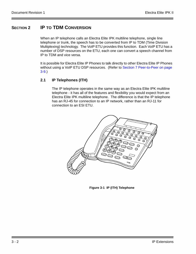
2.1 IP Telephones (ITH)
The IP telephone operates in the same way as an Electra Elite IPK multiline telephone - it has all of the features and flexibility you would expect from an Electra Elite IPK multiline telephone. The difference is that the IP telephone has an RJ-45 for connection to an IP network, rather than an RJ-11 for connection to an ESI ETU.
Figure 3-1 IP (ITH) Telephone
Electra Elite IPK II Document Revision 1
Electra Elite IPK II VoIP Reference Manual 3 - 3
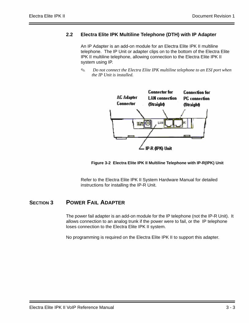
2.2 Electra Elite IPK Multiline Telephone (DTH) with IP Adapter
An IP Adapter is an add-on module for an Electra Elite IPK II multiline telephone. The IP Unit or adapter clips on to the bottom of the Electra Elite IPK II multiline telephone, allowing connection to the Electra Elite IPK II system using IP.
Do not connect the Electra Elite IPK multiline telephone to an ESI port when the IP Unit is installed.
Refer to the Electra Elite IPK II System Hardware Manual for detailed instructions for installing the IP-R Unit.
SECTION 3 POWER FAIL ADAPTER
The power fail adapter is an add-on module for the IP telephone (not the IP-R Unit). It allows connection to an analog trunk if the power were to fail, or the IP telephone loses connection to the Electra Elite IPK II system.
No programming is required on the Electra Elite IPK II to support this adapter.
Figure 3-2 Electra Elite IPK II Multiline Telephone with IP-R(IPK) Unit
Document Revision 1 Electra Elite IPK II
3 - 4 IP Extensions
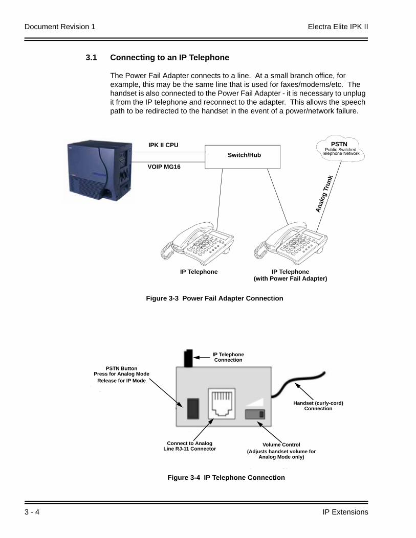
3.1 Connecting to an IP Telephone
The Power Fail Adapter connects to a line. At a small branch office, for example, this may be the same line that is used for faxes/modems/etc. The handset is also connected to the Power Fail Adapter - it is necessary to unplug it from the IP telephone and reconnect to the adapter. This allows the speech path to be redirected to the handset in the event of a power/network failure.
Figure 3-3 Power Fail Adapter Connection
IPK II CPU
VOIP MG16
Switch/Hub
IP Telephone IP Telephone(with Power Fail Adapter)
PSTN
Anal
og T
runk
Public Switched Telephone Network
Figure 3-4 IP Telephone Connection
Connect to Analog Line RJ-11 Connector
PSTN ButtonPress for Analog Mode
Release for IP Mode
Volume Control(Adjusts handset volume for
Analog Mode only)
Handset (curly-cord) Connection
IP Telephone Connection
Electra Elite IPK II Document Revision 1
Electra Elite IPK II VoIP Reference Manual 3 - 5
3.2 Operation During Power Failure
In the event that the telephone becomes disconnected from the power supply (e.g., power cut) the telephone display is blank.
To make a call, lift the handset to receive dial tone from the analog line. Dial as normal.
If a call is received on the analog line, the Power Fail Adapter rings. Lift the handset to answer.
In the event the telephone is connected to the power supply, but disconnected from the Electra Elite IPK II system (e.g., Data network failure), the IP telephone attempts to reconnect. If this fails, press the button on the back of the adapter. This puts the IP telephone into analog node. The telephone display shows “LINE -> PSTN”.
To make a call, lift the handset to receive dial tone from the analog line. Dial as normal.
If a call is received on the analog line, the Power Fail Adapter rings. Lift the handset to answer.
Handsfree (Speaker) mode is not supported on calls made to or from the Power Fail Adapter the handset must always be used.
Document Revision 1 Electra Elite IPK II
3 - 6 IP Extensions
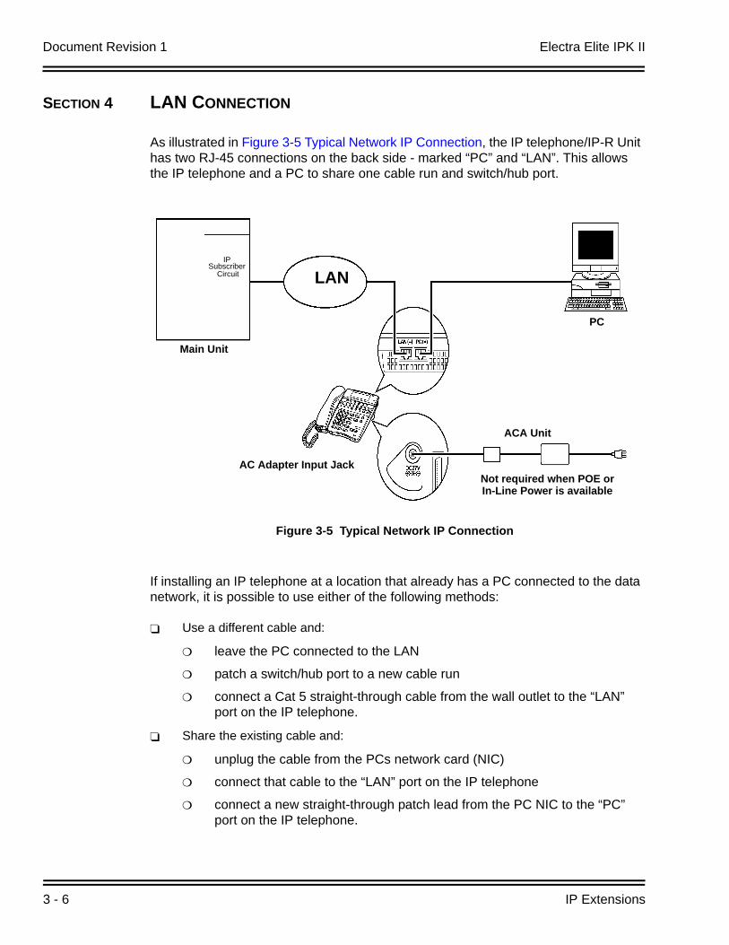
SECTION 4 LAN CONNECTION
As illustrated in Figure 3-5 Typical Network IP Connection, the IP telephone/IP-R Unit has two RJ-45 connections on the back side - marked “PC” and “LAN”. This allows the IP telephone and a PC to share one cable run and switch/hub port.
If installing an IP telephone at a location that already has a PC connected to the data network, it is possible to use either of the following methods:
Use a different cable and:
leave the PC connected to the LAN
patch a switch/hub port to a new cable run
connect a Cat 5 straight-through cable from the wall outlet to the “LAN” port on the IP telephone.
Share the existing cable and:
unplug the cable from the PCs network card (NIC)
connect that cable to the “LAN” port on the IP telephone
connect a new straight-through patch lead from the PC NIC to the “PC” port on the IP telephone.
Figure 3-5 Typical Network IP Connection
LAN
AC Adapter Input Jack
ACA Unit
Main Unit
Not required when POE or In-Line Power is available
IP
Subscriber Circuit
PC
Electra Elite IPK II Document Revision 1
Electra Elite IPK II VoIP Reference Manual 3 - 7
SECTION 5 PROVIDING POWER
IP telephones require power to function. This can be provided in various ways:
5.1 Local Power
The IP telephone and IP-R Unit have a connector for external power. This is supplied by a AC adapter that outputs 27V DC. This means that a main socket is required in the vicinity of each IP Phone, and loss of mains power in the building will prevent the phones from working.
You should only use the power supply supplied by NEC.
5.2 Powered Patch Panel
A powered patch panel has two RJ-45 connectors per IP Phone. One port connects to the switch/hub, and the other port connects to the IP Phone. The patch panel has an integral power supply that adds power to the spare pins of the RJ-45.
When the IP Phone is connected to the powered patch panel, it automatically receives its power via the spare pairs on the Cat-5 cable - there is no need for a local power adapter.
5.3 Power Over Ethernet (PoE)
A PoE switch is a switched hub that also provides power over the spare pairs. The switch can be used with any device (not just IP phones) and will detect if power is required or not. As all of the phones receive their power from one device, it is easy to protect the IP phones from loss of power (by connecting the PoE switch to a UPS).
Document Revision 1 Electra Elite IPK II
3 - 8 IP Extensions
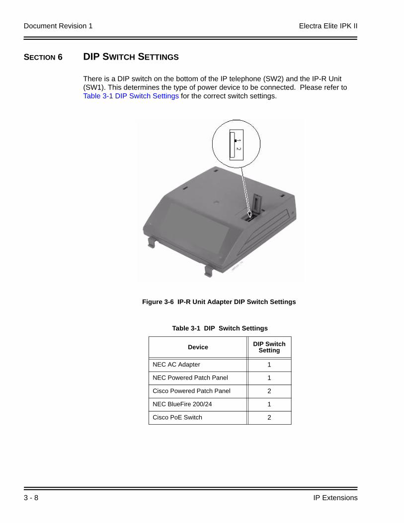
SECTION 6 DIP SWITCH SETTINGS
There is a DIP switch on the bottom of the IP telephone (SW2) and the IP-R Unit (SW1). This determines the type of power device to be connected. Please refer to Table 3-1 DIP Switch Settings for the correct switch settings.
Figure 3-6 IP-R Unit Adapter DIP Switch Settings
Table 3-1 DIP Switch Settings
Device DIP Switch Setting
NEC AC Adapter 1
NEC Powered Patch Panel 1
Cisco Powered Patch Panel 2
NEC BlueFire 200/24 1
Cisco PoE Switch 2
Electra Elite IPK II Document Revision 1
Electra Elite IPK II VoIP Reference Manual 3 - 9
SECTION 7 PEER-TO-PEER
An IP telephone can send and receive RTP packets to/from another IP telephone without using DSP resources on a VOIP ETU. This operation only allows Intercom calls between the IP telephones.
If an Electra Elite IPK II multiline telephone, or trunk line is required, a DSP resource is needed and a VOIP ETU must be installed. If, while on a peer-to-peer call, a conference call is initiated, the peer-to-peer connection is released and a new non peer-to-peer connection is created using the VOIP ETU. If the third party drops out of the conversation, the call reverts to a peer-to-peer call (silence may be heard while this conversion is made by the system).
Although the peer-to-peer feature is supported for IP Station-to-IP Station calls, the Elite IPK II KSU must still have a registered VOIP ETU installed in the system.
With Barge-In, a short silence may be heard if the following occurs:
a peer-to-peer call receives a Barge-In without a Barge-In tone.
a peer-to-peer call receives a Barge-In with Monitor mode.
when the established Barge-In is disconnected.
The Peer-to-Peer feature is a programmable feature that may be enabled or disabled by accessing Data Program 10-26-01 – Peer to Peer.
SECTION 8 PROGRAMMING
The first step to connecting IP telephones to the Electra Elite IPK II system is to connect the IPK II system to the customer’s data network (refer to Chapter 2 General IP Configuration). Next, program the VoIP ETU and associated IP telephone settings. To complete the installation, program the IP telephone.
The programming commands required to complete this installation are located in Chapter 5 Programming. This section provides a brief description of the commonly used commands:
10-12-01 CPUII Network Setup - IP Address Select the IP address for the IP connection (default: 172.16.0.10). A static IP address is required by the CPU II.
10-12-02 CPUII Network Setup - Subnet Mask Select the Subnet Mask to be used (default: 255.255.0.0).
Document Revision 1 Electra Elite IPK II
3 - 10 IP Extensions
10-12-03 CPUII Network Setup - Default Gateway If required, select the default gateway IP address to be used when using a router (default: 0.0.0.0).
10-26-01 Peer-to-PeerUse this Data Program to enable or disable the Peer-to-Peer feature between Megaco IP Stations.
Disabling this feature results in Megaco IP Station-to-Megaco IP Station calls utilizing DSP Resources.
15-05-15 IP Telephone Terminal Basic Data Setup - CODEC TypeFor each IP telephone, set which CODEC Type to use.
84-05-01 VOIP IP Address - IP Address For each VOIP ETU, enter the IP address for the VOIP ETU (default: slot 1=172.16.0.20, slot 2 = 172.16.0.21, etc.). This entry becomes invalid if Program 84-04 is set to "1" (DHCP enabled).
84-06-01 VoIP Info - RTP Port Number For each VOIP ETU, enter the RTP port number (default: 10020).
84-11-28 Dterm IP CODEC Information Basic Setup - Audio Capability PriorityFor each Type, set the CODEC to use (default: G.711).
8.1 System Tones and Ring Tones
IP Phones do not use Program 80-01: Service Tone Setup entries. The tones are generated locally by the IP telephone. When a Door Box chime rings an IP telephone, the system activates the chimes using a ring command. Because of this, if the volume is adjusted while the door chime is sounding, the ringing volume of the IP Phone will be adjusted.
8.2 Music on Hold
In addition, Music on Hold is also provided by the IP telephone. The settings in Program 10-04 : Music on Hold Setup are ignored except to determine whether or not music should be provided. If 10-04-02 is set to "0", no music on hold will be heard. If 10-04-02 is set to "1" or "2", music will be provided by the IP telephone, but there is only one music selection.
SECTION 9 CONFIGURATION EXAMPLES
The following examples below show typical scenarios and basic programming required. These examples assume that the programming steps below are performed on a default system (i.e., no existing configuration).
Electra Elite IPK II Document Revision 1
Electra Elite IPK II VoIP Reference Manual 3 - 11
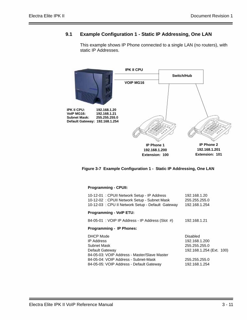
9.1 Example Configuration 1 - Static IP Addressing, One LAN
This example shows IP Phone connected to a single LAN (no routers), with static IP Addresses.
Figure 3-7 Example Configuration 1 - Static IP Addressing, One LAN
Programming - CPUII:
10-12-01 : CPUII Network Setup - IP Address10-12-02 : CPUII Network Setup - Subnet Mask10-12-03 : CPU II Network Setup - Default Gateway
192.168.1.20255.255.255.0 192.168.1.254
Programming - VoIP ETU:
84-05-01 : VOIP IP Address - IP Address (Slot #) 192.168.1.21
Programming - IP Phones:
DHCP Mode IP AddressSubnet MaskDefault Gateway 84-05-03: VOIP Address - Master/Slave Master84-05-04: VOIP Address - Subnet-Mask84-05-05: VOIP Address - Default Gateway
Disabled192.168.1.200255.255.255.0 192.168.1.254 (Ext. 100)
255.255.255.0 192.168.1.254
IPK II CPU
VOIP MG16
Switch/Hub
IP Phone 1192.168.1.200
Extension: 100
IP Phone 2192.168.1.201
Extension: 101
IPK II CPU: 192.168.1.20VoIP MG16: 192.168.1.21Subnet Mask: 255.255.255.0Default Gateway: 192.168.1.254

Document Revision 1 Electra Elite IPK II
3 - 12 IP Extensions
9.2 Example Configuration 2 - Dynamic IP Addressing, One LAN
This example shows System IP Phones connected to a single LAN (no routers), with dynamic IP Addresses. The DHCP server could be:
customer supplied (e.g., Windows 2003 server)
inDHCP internal DHCP server.
In this case, additional programming would be required. Refer to Chapter Chapter 2 General IP Configuration and Figure 3-8 Example Configuration 2 - Dynamic IP Addressing, One LAN.
Figure 3-8 Example Configuration 2 - Dynamic IP Addressing, One LAN
Programming - CPUII:
10-12-01 : CPUII Network Setup - IP Address10-12-02 : CPUII Network Setup - Subnet Mask10-12-03 : CPUII Network Setup - Default Gateway 10-13-01 : In-DHCP Server Setup - DHCP Server Mode10-14-01 : Managed Network Setup (Scope 1)
192.168.1.20255.255.255.0 192.168.1.254On192.168.1.200 Min 192.168.1.250 Max
Programming - VoIP ETU:
10-16-01: Option information Setup - Router (Route No. 3)10-16-05 : Option information MGC (No. 129) 84-05-01 : VoIP IP Address - IP Address
192.168.1.254192.168.1.21192.168.1.21
IPK II CPU
VOIP MG16
Switch/Hub
IP Phone 1192.168.1.200
Extension: 200
IP Phone 2192.168.1.201
Extension: 201
IPK II CPU: 192.168.1.20VoIP MG16: 192.168.1.21Subnet Mask: 255.255.255.0Default Gateway: 192.168.1.254
Electra Elite IPK II Document Revision 1
Electra Elite IPK II VoIP Reference Manual 3 - 13
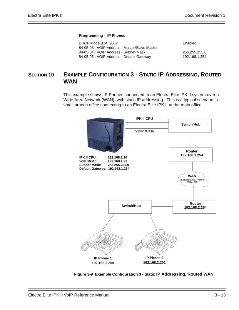
SECTION 10 EXAMPLE CONFIGURATION 3 - STATIC IP ADDRESSING, ROUTED WAN
This example shows IP Phones connected to an Electra Elite IPK II system over a Wide Area Network (WAN), with static IP addressing. This is a typical scenario - a small branch office connecting to an Electra Elite IPK II at the main office.
Programming - IP Phones
DHCP Mode (Ext. 200): 84-05-03 : VOIP Address - Master/Slave Master84-05-04 : VOIP Address - Subnet-Mask84-05-05 : VOIP Address - Default Gateway
Enabled
255.255.255.0192.168.1.254
Figure 3-9 Example Configuration 3 - Static IP Addressing, Routed WAN
IPK II CPU
VOIP MG16
Switch/Hub
IP Phone 1192.168.2.200
IP Phone 2192.168.2.201
IPK II CPU: 192.168.1.20VoIP MG16: 192.168.1.21Subnet Mask: 255.255.255.0Default Gateway: 192.168.1.254
Router192.168.1.254
Switch/Hub
WAN(Leased Line, Frame
Relay, etc.)
Router192.168.2.254
Document Revision 1 Electra Elite IPK II
3 - 14 IP Extensions
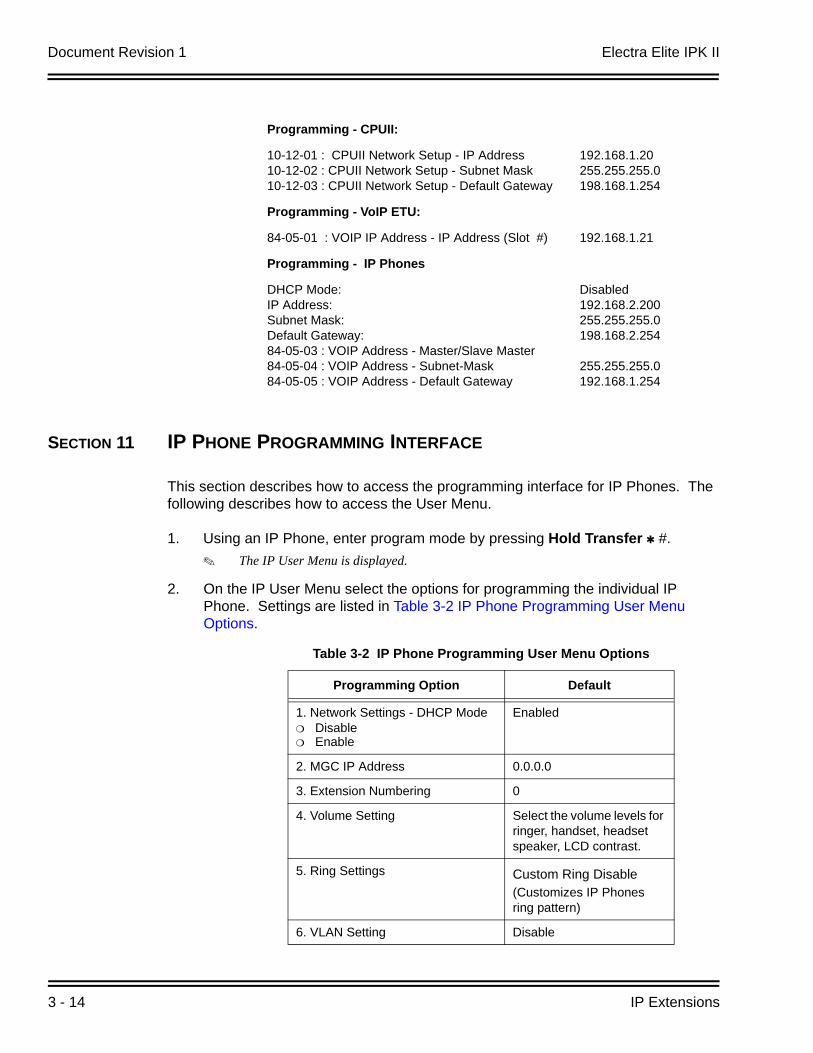
SECTION 11 IP PHONE PROGRAMMING INTERFACE
This section describes how to access the programming interface for IP Phones. The following describes how to access the User Menu.
1. Using an IP Phone, enter program mode by pressing Hold Transfer #. The IP User Menu is displayed.
2. On the IP User Menu select the options for programming the individual IP Phone. Settings are listed in Table 3-2 IP Phone Programming User Menu Options.
Programming - CPUII:
10-12-01 : CPUII Network Setup - IP Address10-12-02 : CPUII Network Setup - Subnet Mask10-12-03 : CPUII Network Setup - Default Gateway
192.168.1.20255.255.255.0 198.168.1.254
Programming - VoIP ETU:
84-05-01 : VOIP IP Address - IP Address (Slot #) 192.168.1.21
Programming - IP Phones
DHCP Mode: IP Address: Subnet Mask:Default Gateway: 84-05-03 : VOIP Address - Master/Slave Master84-05-04 : VOIP Address - Subnet-Mask84-05-05 : VOIP Address - Default Gateway
Disabled192.168.2.200255.255.255.0 198.168.2.254
255.255.255.0192.168.1.254
Table 3-2 IP Phone Programming User Menu Options
Programming Option Default
1. Network Settings - DHCP Mode DisableEnable
Enabled
2. MGC IP Address 0.0.0.0
3. Extension Numbering 0
4. Volume Setting Select the volume levels for ringer, handset, headset speaker, LCD contrast.
5. Ring Settings Custom Ring Disable(Customizes IP Phones ring pattern)
6. VLAN Setting Disable
Electra Elite IPK II Document Revision 1
Electra Elite IPK II VoIP Reference Manual 3 - 15
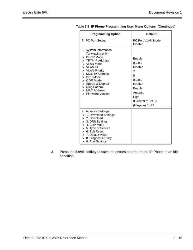
3. Press the SAVE softkey to save the entries and return the IP Phone to an idle condition.
7. PC Port Setting PC Port VLAN Mode Disable
8. System Information (for viewing only)
DHCP ModeTFTP IP AddressVLAN Mode VLAN IDVLAN Priority MGC IP AddressDRS ModeCDP Mode Speed & Duplex Ring PatternMAC AddressFirmware Version
Enable0.0.0.0Disable750.0.0.0DisableEnableAutonegHigh00 60 b9 c1 23 5d(Megaco) 01.27
9. Advance Settings1. Download Settings2. Download3. DRS Settings4. CDP Mode5. Type of Service6. Soft Reset7. Default Value8. Diagnostic Utility9. Port Settings
Table 3-2 IP Phone Programming User Menu Options (Continued)
Programming Option Default
Document Revision 1 Electra Elite IPK II
3 - 16 IP Extensions
SECTION 12 DHCP SERVER CONFIGURATION
It is possible to use either an external DHCP server (e.g., Windows 2003 Server) or the Electra Elite IPK II internal DHCP server. If you intend to use either of these methods with IP Phones, the DHCP server needs to be configured to supply the MGC, DRS, Gateway, TFTP address.
If you are using the internal DHCP server, simply enable the DHCP server (refer to 9.2 Example Configuration 2 - Dynamic IP Addressing, One LAN on page 3-12), then specify the MGC address in PRG10-16-05.
10-16-05 Option Information Setup MGCSpecify the MGC address to provide to the System IP Phones. This is usually the VoIP ETU address.
If using an external DHCP server, it is necessary to add a new Option Code to the DHCP scope for the MGC address. The method for adding this service varies depending on the DHCP server used.
12.1 DHCP Server Configuration Example
The example below shows the necessary steps to add Option 129 to a Windows 2000 Server.
1. Enter Computer Management and expand Service and Applications.
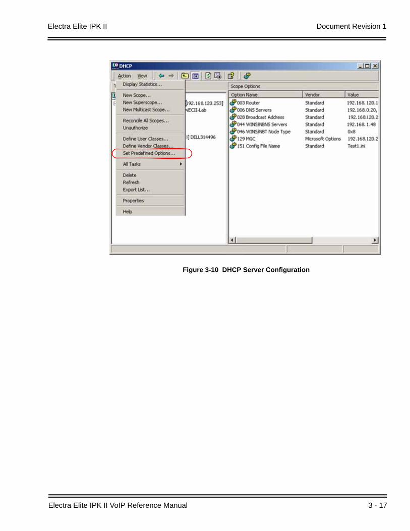
2. Right click on DHCP and click on Set Predefined Options (refer to Figure 3-10 DHCP Server Configuration on page 3-17).
3. When the Predefined Options and Values dialogue box opens, click on Add.
Electra Elite IPK II Document Revision 1
Electra Elite IPK II VoIP Reference Manual 3 - 17
Figure 3-10 DHCP Server Configuration
Document Revision 1 Electra Elite IPK II
3 - 18 IP Extensions
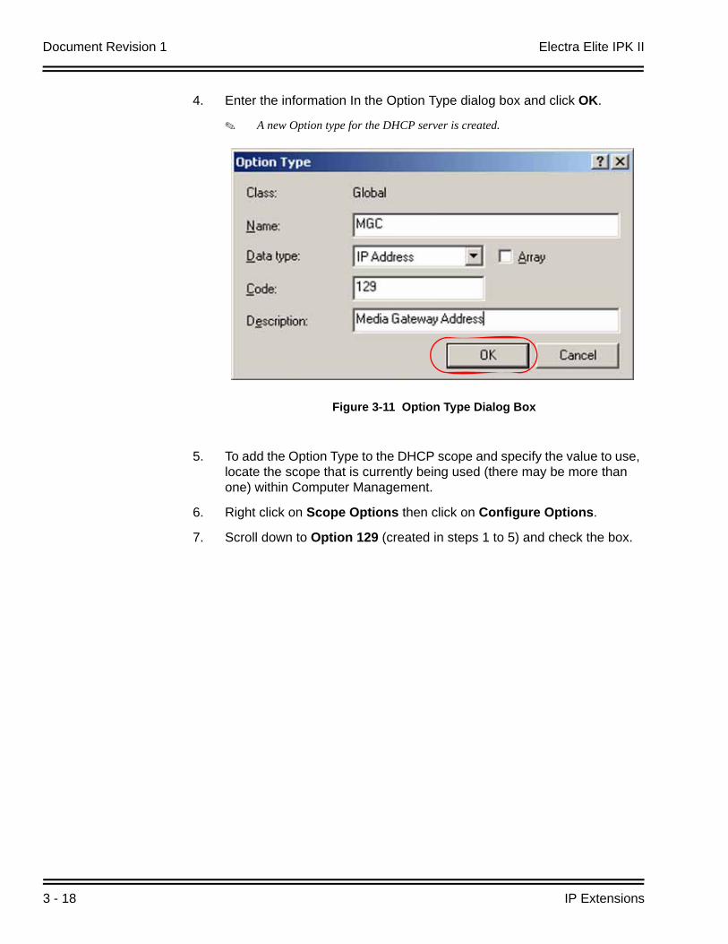
4. Enter the information In the Option Type dialog box and click OK.
A new Option type for the DHCP server is created.
5. To add the Option Type to the DHCP scope and specify the value to use, locate the scope that is currently being used (there may be more than one) within Computer Management.
6. Right click on Scope Options then click on Configure Options.
7. Scroll down to Option 129 (created in steps 1 to 5) and check the box.
Figure 3-11 Option Type Dialog Box
Electra Elite IPK II Document Revision 1
Electra Elite IPK II VoIP Reference Manual 3 - 19
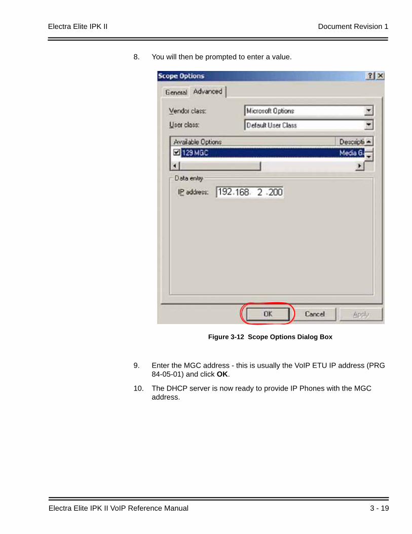
8. You will then be prompted to enter a value.
9. Enter the MGC address - this is usually the VoIP ETU IP address (PRG 84-05-01) and click OK.
10. The DHCP server is now ready to provide IP Phones with the MGC address.
Figure 3-12 Scope Options Dialog Box
Document Revision 1 Electra Elite IPK II
3 - 20 IP Extensions
SECTION 13 CONFIGURING QUALITY OF SERVICE
NEC recommends configuring Quality of Service (QoS) to ensure that the speech quality is not affected by other data on the network. QoS is discussed further in Chapter 6 Network Design Considerations.
The Electra Elite IPK II system supports:
IEEE802.1q (VLAN Tagging)
IEEE802.1p (Priority)
With the VLAN tagging mode, the Electra Elite IPK II system can handle packets with or without a VLAN tag. If the VLAN ID of a packet is different from the registered one, that packet will be dropped.
13.1 Layer 2 Priority Control
Layer 2 priority control can be enabled on an ethernet switch, if it supports VLAN tagging. This allows layer 2 prioritization.
Using a switch that supports 802.1p allows:
priority control
reduction of unnecessary packets (e.g., broadcast packets) and provides circuitry by restricting a broadcast domain
13.1.1 Programming Layer 2 Priority Control
To program Layer 2 for System, VLAN/QoS, use the following programs.
84-09-01 VLAN Setup - VLANEnable the VLAN mode for the system (0=Disable, 1=Enable). The system must be reset in order for the change to take effect. If the VLAN mode is enabled, the Electra Elite IPK II system sends all packets with a VLAN tag - if disabled, no VLAN tag is sent in the packets.
84-09-02 VLAN Setup - VLAN ID Enter the ID to be used for the VLAN (1~4094). The system must be reset in order for the change to take effect.
84-09-03 VLAN Setup - Priority Enter the priority of the VLAN (0~7). The system must be reset in order for the change to take effect.
Electra Elite IPK II Document Revision 1
Electra Elite IPK II VoIP Reference Manual 3 - 21
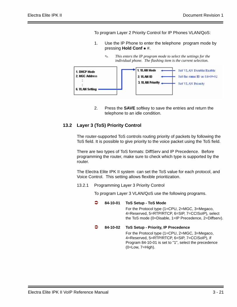
To program Layer 2 Priority Control for IP Phones VLAN/QoS:
1. Use the IP Phone to enter the telephone program mode by pressing Hold Conf #.
This enters the IP program mode to select the settings for the individual phone. The flashing item is the current selection.
2. Press the SAVE softkey to save the entries and return the telephone to an idle condition.
13.2 Layer 3 (ToS) Priority Control
The router-supported ToS controls routing priority of packets by following the ToS field. It is possible to give priority to the voice packet using the ToS field.
There are two types of ToS formats: DiffServ and IP Precedence. Before programming the router, make sure to check which type is supported by the router.
The Electra Elite IPK II system can set the ToS value for each protocol, and Voice Control. This setting allows flexible prioritization.
13.2.1 Programming Layer 3 Priority Control
To program Layer 3 VLAN/QoS use the following programs.
84-10-01 ToS Setup - ToS ModeFor the Protocol type (1=CPU, 2=MGC, 3=Megaco, 4=Reserved, 5=RTP/RTCP, 6=SIP, 7=CCISoIP), select the ToS mode (0=Disable, 1=IP Precedence, 2=Diffserv).
84-10-02 ToS Setup - Priority, IP PrecedenceFor the Protocol type (1=CPU, 2=MGC, 3=Megaco, 4=Reserved, 5=RTP/RTCP, 6=SIP, 7=CCISoIP), if Program 84-10-01 is set to "1", select the precedence (0=Low, 7=High).
Document Revision 1 Electra Elite IPK II
3 - 22 IP Extensions
84-10-03 ToS Setup - Low Delay For the Protocol type (1=CPU, 2=MGC, 3=Megaco, 4=Reserved, 5=RTP/RTCP, 6=SIP, 7=CCISoIP), if Program 84-10-01 is set to "1", select the delay (0=Normal Delay, 1=Low Delay).
84-10-04 ToS Setup - Wide Band (Throughout)For the Protocol type (1=CPU, 2=MGC, 3=Megaco, 4=Reserved, 5=RTP/RTCP, 6=SIP, 7=CCISoIP), if Program 84-10-01 is set to "1", select the throughput (0=Normal Throughput, 1=High Throughput).
84-10-05 ToS Setup - High ReliabilityFor the Protocol type (1=CPU, 2=MGC, 3=Megaco, 4=Reserved, 5=RTP/RTCP, 6=SIP, 7=CCISoIP), if Program 84-10-01 is set to "1", select the reliability (0=Normal Reliability, 1=High Reliability).
84-10-06 ToS Setup - Low Cost For the Protocol type (1=CPU, 2=MGC, 3=Megaco, 4=Reserved, 5=RTP/RTCP, 6=SIP, 7=CCISoIP), if Program 84-10-01 is set to "1", select the low cost mode (0=Normal Cost, 1=Low Cost).
84-10-07 ToS Setup - Priority (D.S.C.P. - Differentiated Services Code Point)For the Protocol type (1=CPU, 2=MGC, 3=Megaco, 4=Reserved, 5=RTP/RTCP, 6=SIP, 7=CCISoIP), if Program 84-10-01 is set to "2", select the Diffserv priority (0~63).
SECTION 14 IP TELEPHONE REGISTRATION AND DELETION
When a IP Phone connects to the Electra Elite IPK II system, it is assigned the first available port, starting from the value set in Program 11-02-01.
The ports are allocated in blocks of four.
For example:
Insert an MG16 ETU.
Program 11-02-01 Extension Numbering.
Configure a System IP Phone and connect to the LAN.
The IP Phone takes port 17 (extension 216 by default).
Electra Elite IPK II Document Revision 1
Electra Elite IPK II VoIP Reference Manual 3 - 23
Ports 18~ 20 are also allocated for use by IP Phones - the next IP Phone to connect takes port 18.
If a second extension ETU (e.g., ESI ETU or SLI ETU) is inserted, it takes port 21 and higher.
When connecting an IP Phone, the MAC address (ID) is automatically registered in Program 15-05-02. If the registration in Program 15-05-02 is made manually (before connecting the telephone) it uses the assigned port number when the telephone is connected. The MAC address is printed on the barcode label on the bottom of the telephone or IP-R Unit. It is a 12-digit alphanumeric number, ranging from 0~9 and A~F.
To delete a telephone registration:
Enter Program 90-23-01, then enter the extension number of the IP Phone. Press 1 and then Hold to delete the registration.
SECTION 15 SYSTEM IP PHONES AND ANALOG TRUNKS
NEC does not recommend using IP Phones with analog trunks. Due to the nature of analog-to-digital conversion, considerable echo is created, which cannot be removed by the Electra Elite IPK II echo canceller. Digital (ISDN) trunks do not suffer from this problem.
For outgoing calls:Ensure that there are no analog trunk ports (COI ETU or TLI ETU) in the trunk routes (PRG 21-02).
For incoming calls:Ensure that there are no IP Phones in the trunk targets (PRG22-04 and 22-07).
For transferred calls:It is not possible to stop an analog trunk call being transferred to an IP Phone. It is important that the end-user is made aware of this limitation.
SECTION 16 FIRMWARE UPGRADE PROCEDURE
Occasionally, NEC releases a new version of firmware for the IP Phones. This firmware can be applied automatically or manually.
The upgrade requires the use of a TFTP server. This is a software package that runs on a PC. (These can be downloaded from the internet - usually they are freeware/shareware.)
Document Revision 1 Electra Elite IPK II
3 - 24 IP Extensions
16.1 Manually Upgrading Firmware
Manually upgrading the firmware uses a uses a TFTP server, but requires the engineer visit each IP Phone individually. This may take longer, but is more controlled as the downloads can be staggered to avoid excessive bandwidth utilization.
To manually upgrade the firmware:
1. Install and configure a TFTP server.
2. Copy the firmware file (apph248.hex for IP Adapter or apph248.out for IP Phone) to the default TFTP directory.
3. On the IP Phone, enter programming mode (Hold, Conf, , #).
4. Enter Maintenance Mode (Hold, #, 0).
5. Enter the TFTP server IP address in “Option 1 - Download settings”.
6. Enter Download menu (option 2).
7. Press 1 - for “Program”.
8. Press the softkey.
The IP Phone attempts to download the firmware from the TFTP server and reboots when the download is complete.
16.2 Checking the Firmware Version
To check the IP Phone firmware version:
1. On the System IP Phone, enter programming mode (Hold, Conf, , #).
2. Enter 8 - for Information.
3. Press the Up softkey.
The Firmware Version is displayed.
16.3 Upgrading Automatically
This procedure causes all IP Phones to attempt firmware upgrade the next time they connect to the CPU II. This can make the upgrade procedure easier, as it is not necessary to visit every telephone to perform the upgrade.
This can cause problems if, for example, a PoE (Power over Internet) switch is used. In this case, when the PoE switch is powered up, all telephones connect to the TFTP server at the same time. This causes a large amount of data for the TFTP server to transfer over the data network.
Electra Elite IPK II Document Revision 1
Electra Elite IPK II VoIP Reference Manual 3 - 25
To avoid this, connect the telephones to the PoE switch gradually, allowing time for each telephone to upgrade before connecting the next.
To enable automatic upgrade:
1. Install and configure an TFTP server.
2. Copy the firmware file (apph248.hex for IP-Adapter or apph248.out for IP-Phone) to the default TFTP directory
3. Set the server mode to TFTP in PRG84-07-01 and specify the IP address of the TFTP server (this is the PC where the TFTP software is installed) in PRG 84-07-02.
4. For each type of System IP Phone, set the Hardware type: PRG 90-22-01.
5. The telephones that are currently supported are:
02: IP Adapter
04: IP Phone (North America)
6. Set the required firmware version in PRG 90-22-02. This should be set to the version number that is available on the TFTP server.
7. Reboot the IP Phone. The IP Phone compares the version of firmware currently installed with the firmware specified in PRG90-22. If they are different, the IP Phone attempts to download the firmware from TFTP. If the download is successful, the IP Phone checks that the firmware it has installed matches PRG 90-22. If this is the case, the telephone reconnects. If it is not the same, the telephone restarts the procedure.

Document Revision 1 Electra Elite IPK II
3 - 26 IP Extensions
THIS PAGE INTENTIONALLY LEFT BLANK
Electra Elite IPK II VoIP Reference Manual 4 - 1
IP N
etw
orkin
g
4IP Networking
SECTION 1 INTRODUCTION1
IP Networking uses VoIP technology to connect two or more telephone systems together. This allows calls to be made between sites without using the public telephone network. This can save a considerable amount of money, and can makes communication between sites much easier.
There are two types of IP Networking available on the Electra Elite IPK II – IPK II CCIS Network and SIP trunks. These methods are explained below.
SECTION 2 IPK II CCISOIP NETWORK
The IPK II CCIS Network package provides a seamless connection of multiple systems into a single “virtual” communications system using or VoIP lines with a unified numbering plan.
IPK II CCIS Network allows many offices to connect their Electra Elite IPK II systems so they appear as one. This will give them the ability to have only one operator to manage the system and share one voice mail system within the network.
An extension user in the network can easily dial another extension or transfer a call within the IPK II CCIS Network system. Calls are passed from network node to network node using a protocol that contains information about the source of the call, the type of call and the destination of the call.
1. The voice quality of VoIP is dependent on variables such as available bandwidth, network latency and Quality of Service (QoS) initiatives, all of which are controlled by the network and internet service providers. Because these variables are not in NEC’s control, it cannot guarantee the performance of the user’s IP-based remote voice solution. Therefore, NEC recommends connecting VoIP equipment through a local area network using a Private IP address.
Document Revision 1 Electra Elite IPK II
4 - 2 IP Networking
IPK II K-CCIS is explained in detail in the Electra Elite IPK II Key-Common Channel Interoffice Signaling (K-CCIS) Manual. Please refer to this for a complete description and installation instructions.
SECTION 3 IP TRUNKS
The SIP Trunks method of networking allows connection to SIP devices. This could be a PBX system or a third-party product. The feature set is limited when using SIP, it is not possible to use the advanced networking features (if these features are required, use IP CCIS.
Refer to Chapter 8 SIP Trunking for a a detailed description of SIP trunking and for set up instructions.
To set up IP trunks:
4. Connect the system to the Data Network. (Refer to Chapter 2 General IP Configuration for detailed instructions.)
5. Configure the IP trunks.
6. Configure the CCISoIP or SIP information.
7. Configure the F-route.
3.1 Configure IP Trunks
When installing a PVA(X)-U10 ETU in the Electra Elite IPK II system, external line ports are allotted in accordance with the number of Licensed ports for the particular IP Application.
The Electra Elite IPK II system now has the required information about the remote destinations and the SIP/CCISoIP configuration is complete. The only remaining task is to configure F-Route to route calls to remote destinations via the IP trunks. F-Route configuration is discussed in detail in the Automatic Route Selection (ARS) feature in the Electra Elite IPK II Programming Manual. A basic list of the programming commands required for F-route is shown in the example below.
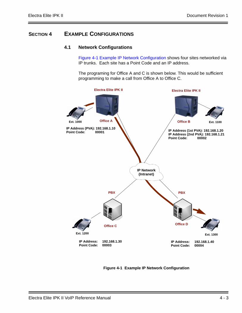
Electra Elite IPK II Document Revision 1
Electra Elite IPK II VoIP Reference Manual 4 - 3
SECTION 4 EXAMPLE CONFIGURATIONS
4.1 Network Configurations
Figure 4-1 Example IP Network Configuration shows four sites networked via IP trunks. Each site has a Point Code and an IP address.
The programing for Office A and C is shown below. This would be sufficient programming to make a call from Office A to Office C.
Figure 4-1 Example IP Network Configuration
IP Address (PVA): 192.168.1.10Point Code: 00001
Ext. 1000 Ext. 1100
Electra Elite IPK II
Office A
IP Network(Intranet)
Ext. 1200
IP Address (1st PVA): 192.168.1.20IP Address (2nd PVA): 192.168.1.21Point Code: 00002
Electra Elite IPK II
Office B
Ext. 1300
IP Address: 192.168.1.30Point Code: 00003
PBX
Office C Office D
IP Address: 192.168.1.40Point Code: 00004
PBX
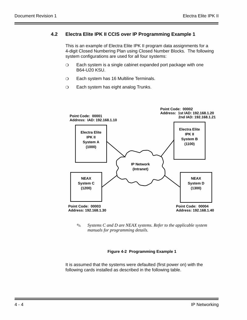
Document Revision 1 Electra Elite IPK II
4 - 4 IP Networking
4.2 Electra Elite IPK II CCIS over IP Programming Example 1
This is an example of Electra Elite IPK II program data assignments for a 4-digit Closed Numbering Plan using Closed Number Blocks. The following system configurations are used for all four systems:
Each system is a single cabinet expanded port package with one B64-U20 KSU.
Each system has 16 Multiline Terminals.
Each system has eight analog Trunks.
It is assumed that the systems were defaulted (first power on) with the following cards installed as described in the following table.
Figure 4-2 Programming Example 1
Electra EliteIPK II
System A(1000)
Electra EliteIPK II
System B(1100)
NEAXSystem D
(1300)
NEAXSystem C
(1200)
Point Code: 00002Address: 1st IAD: 192.168.1.20 2nd IAD: 192.168.1.21
IP Network(Intranet)
Point Code: 00004Address: 192.168.1.40
Point Code: 00003Address: 192.168.1.30
Point Code: 00001Address: IAD: 192.168.1.10
Systems C and D are NEAX systems. Refer to the applicable system manuals for programming details.
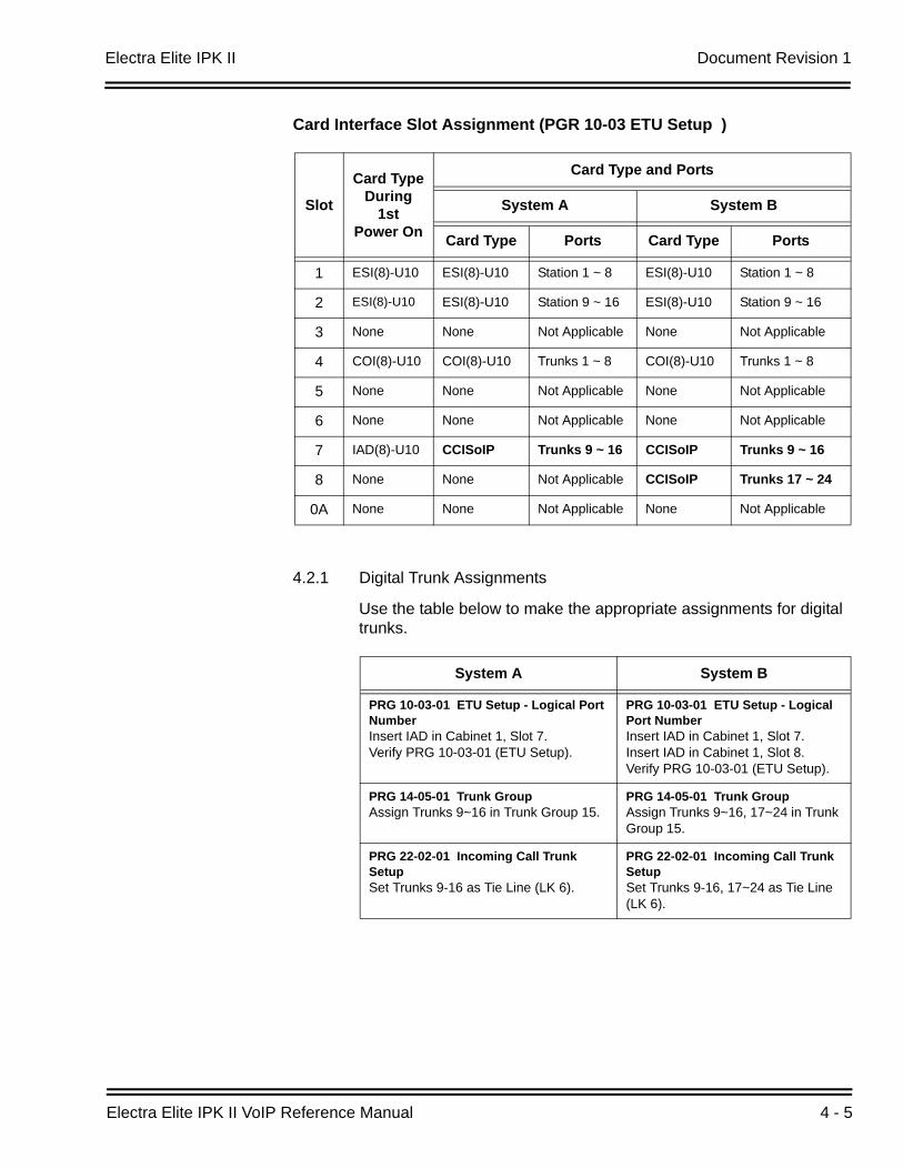
Electra Elite IPK II Document Revision 1
Electra Elite IPK II VoIP Reference Manual 4 - 5
Card Interface Slot Assignment (PGR 10-03 ETU Setup )
4.2.1 Digital Trunk Assignments
Use the table below to make the appropriate assignments for digital trunks.
Slot
Card TypeDuring
1stPower On
Card Type and Ports
System A System B
Card Type Ports Card Type Ports
1 ESI(8)-U10 ESI(8)-U10 Station 1 ~ 8 ESI(8)-U10 Station 1 ~ 8
2 ESI(8)-U10 ESI(8)-U10 Station 9 ~ 16 ESI(8)-U10 Station 9 ~ 16
3 None None Not Applicable None Not Applicable
4 COI(8)-U10 COI(8)-U10 Trunks 1 ~ 8 COI(8)-U10 Trunks 1 ~ 8
5 None None Not Applicable None Not Applicable
6 None None Not Applicable None Not Applicable
7 IAD(8)-U10 CCISoIP Trunks 9 ~ 16 CCISoIP Trunks 9 ~ 16
8 None None Not Applicable CCISoIP Trunks 17 ~ 24
0A None None Not Applicable None Not Applicable
System A System B
PRG 10-03-01 ETU Setup - Logical Port NumberInsert IAD in Cabinet 1, Slot 7.Verify PRG 10-03-01 (ETU Setup).
PRG 10-03-01 ETU Setup - Logical Port NumberInsert IAD in Cabinet 1, Slot 7.Insert IAD in Cabinet 1, Slot 8.Verify PRG 10-03-01 (ETU Setup).
PRG 14-05-01 Trunk GroupAssign Trunks 9~16 in Trunk Group 15.
PRG 14-05-01 Trunk GroupAssign Trunks 9~16, 17~24 in Trunk Group 15.
PRG 22-02-01 Incoming Call Trunk SetupSet Trunks 9-16 as Tie Line (LK 6).
PRG 22-02-01 Incoming Call Trunk SetupSet Trunks 9-16, 17~24 as Tie Line (LK 6).
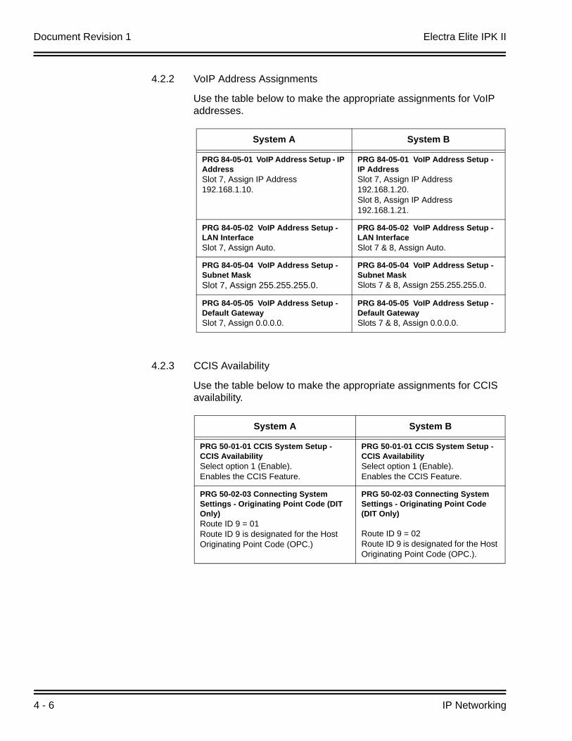
Document Revision 1 Electra Elite IPK II
4 - 6 IP Networking
4.2.2 VoIP Address Assignments
Use the table below to make the appropriate assignments for VoIP addresses.
4.2.3 CCIS Availability
Use the table below to make the appropriate assignments for CCIS availability.
System A System B
PRG 84-05-01 VoIP Address Setup - IP AddressSlot 7, Assign IP Address 192.168.1.10.
PRG 84-05-01 VoIP Address Setup - IP AddressSlot 7, Assign IP Address 192.168.1.20.Slot 8, Assign IP Address 192.168.1.21.
PRG 84-05-02 VoIP Address Setup - LAN Interface Slot 7, Assign Auto.
PRG 84-05-02 VoIP Address Setup - LAN InterfaceSlot 7 & 8, Assign Auto.
PRG 84-05-04 VoIP Address Setup - Subnet MaskSlot 7, Assign 255.255.255.0.
PRG 84-05-04 VoIP Address Setup - Subnet MaskSlots 7 & 8, Assign 255.255.255.0.
PRG 84-05-05 VoIP Address Setup - Default GatewaySlot 7, Assign 0.0.0.0.
PRG 84-05-05 VoIP Address Setup - Default GatewaySlots 7 & 8, Assign 0.0.0.0.
System A System B
PRG 50-01-01 CCIS System Setup - CCIS AvailabilitySelect option 1 (Enable).Enables the CCIS Feature.
PRG 50-01-01 CCIS System Setup - CCIS AvailabilitySelect option 1 (Enable).Enables the CCIS Feature.
PRG 50-02-03 Connecting System Settings - Originating Point Code (DIT Only)Route ID 9 = 01Route ID 9 is designated for the Host Originating Point Code (OPC.)
PRG 50-02-03 Connecting System Settings - Originating Point Code (DIT Only)
Route ID 9 = 02Route ID 9 is designated for the Host Originating Point Code (OPC.).
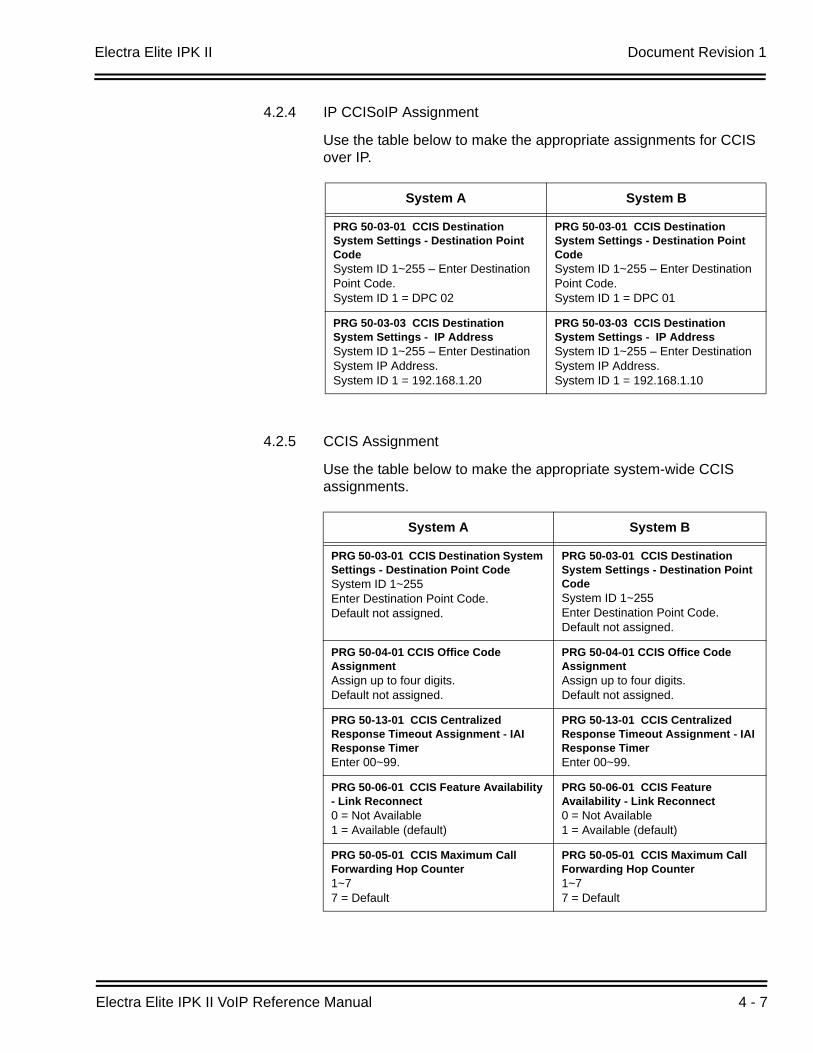
Electra Elite IPK II Document Revision 1
Electra Elite IPK II VoIP Reference Manual 4 - 7
4.2.4 IP CCISoIP Assignment
Use the table below to make the appropriate assignments for CCIS over IP.
4.2.5 CCIS Assignment
Use the table below to make the appropriate system-wide CCIS assignments.
System A System B
PRG 50-03-01 CCIS Destination System Settings - Destination Point CodeSystem ID 1~255 – Enter Destination Point Code.System ID 1 = DPC 02
PRG 50-03-01 CCIS Destination System Settings - Destination Point CodeSystem ID 1~255 – Enter Destination Point Code.System ID 1 = DPC 01
PRG 50-03-03 CCIS Destination System Settings - IP AddressSystem ID 1~255 – Enter Destination System IP Address.System ID 1 = 192.168.1.20
PRG 50-03-03 CCIS Destination System Settings - IP AddressSystem ID 1~255 – Enter Destination System IP Address.System ID 1 = 192.168.1.10
System A System B
PRG 50-03-01 CCIS Destination System Settings - Destination Point CodeSystem ID 1~255 Enter Destination Point Code.Default not assigned.
PRG 50-03-01 CCIS Destination System Settings - Destination Point CodeSystem ID 1~255 Enter Destination Point Code.Default not assigned.
PRG 50-04-01 CCIS Office Code AssignmentAssign up to four digits.Default not assigned.
PRG 50-04-01 CCIS Office Code AssignmentAssign up to four digits.Default not assigned.
PRG 50-13-01 CCIS Centralized Response Timeout Assignment - IAI Response TimerEnter 00~99.
PRG 50-13-01 CCIS Centralized Response Timeout Assignment - IAI Response TimerEnter 00~99.
PRG 50-06-01 CCIS Feature Availability - Link Reconnect0 = Not Available1 = Available (default)
PRG 50-06-01 CCIS Feature Availability - Link Reconnect0 = Not Available1 = Available (default)
PRG 50-05-01 CCIS Maximum Call Forwarding Hop Counter1~77 = Default
PRG 50-05-01 CCIS Maximum Call Forwarding Hop Counter1~77 = Default

Document Revision 1 Electra Elite IPK II
4 - 8 IP Networking
4.2.6 Centralized Day Night Switching Assignments
Use the table below to make the appropriate assignments for centralized day and night switching.
4.2.7 Centralized BLF Assignments
Use the table below to make the appropriate assignments for centralized BLF.
System A System B
PRG 50-06-02 CCIS Feature Availability - Centralized Day/Night Switching 0 = Disable (default)1 = Enable
MB 1-15-13 Centralized Day/Night Switching for Remote Office AssignmentSelect Data:LK 1 = Deny (default)LK 2 = Allow
PRG 50-11-02 CCIS Centralized Day/Night Switching Sending Group Assignment - CCIS Route IDSend Group (1~8)CCIS Route ID0 = No Setting (default)1~4
MB 1-15-14 Centralized Day/Night Switching for Main Office AssignmentSelect Table 01~16.Enter Point Code (00001~16367).Enter CCH Channel (1~4) or i.
PRG 50-12-01 CCIS Centralized Day/Night Mode to System Mode Assignment - Day ModeDay Mode = Mode 1~81 = defaultNight Mode = Mode 1~82 = default
Not Applicable
System A System B
PRG 50-08-01 CCIS Centralized BLF Sending Group Assignment - Destination Point CodeSelect Group ID (1~8) + Destination Point Code.Default not assigned.
MB 1-15-15 Centralized BLF Send Point Code Assignment1. Select Table (1~8).2. Enter Point Code (00001~16367).
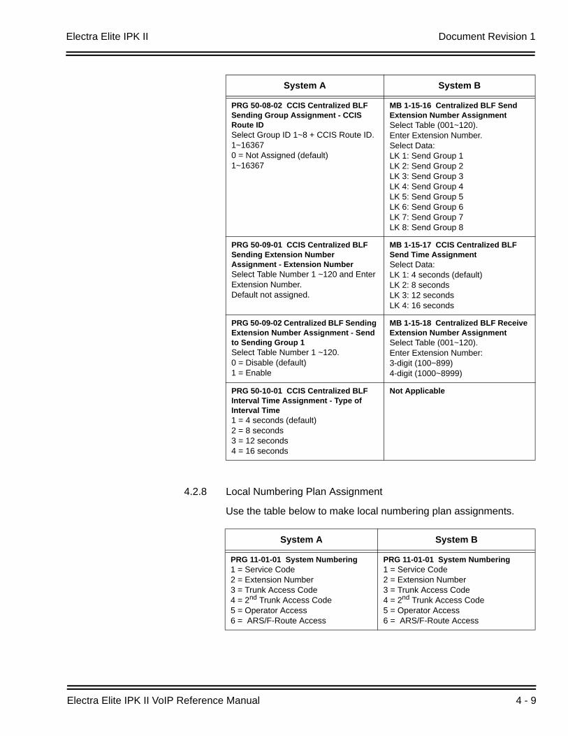
Electra Elite IPK II Document Revision 1
Electra Elite IPK II VoIP Reference Manual 4 - 9
4.2.8 Local Numbering Plan Assignment
Use the table below to make local numbering plan assignments.
PRG 50-08-02 CCIS Centralized BLF Sending Group Assignment - CCIS Route IDSelect Group ID 1~8 + CCIS Route ID. 1~163670 = Not Assigned (default)1~16367
MB 1-15-16 Centralized BLF Send Extension Number AssignmentSelect Table (001~120).Enter Extension Number.Select Data:LK 1: Send Group 1LK 2: Send Group 2LK 3: Send Group 3LK 4: Send Group 4LK 5: Send Group 5LK 6: Send Group 6LK 7: Send Group 7LK 8: Send Group 8
PRG 50-09-01 CCIS Centralized BLF Sending Extension Number Assignment - Extension Number Select Table Number 1 ~120 and Enter Extension Number.Default not assigned.
MB 1-15-17 CCIS Centralized BLF Send Time AssignmentSelect Data:LK 1: 4 seconds (default)LK 2: 8 secondsLK 3: 12 secondsLK 4: 16 seconds
PRG 50-09-02 Centralized BLF Sending Extension Number Assignment - Send to Sending Group 1Select Table Number 1 ~120.0 = Disable (default)1 = Enable
MB 1-15-18 Centralized BLF Receive Extension Number AssignmentSelect Table (001~120).Enter Extension Number:3-digit (100~899)4-digit (1000~8999)
PRG 50-10-01 CCIS Centralized BLF Interval Time Assignment - Type of Interval Time1 = 4 seconds (default)2 = 8 seconds3 = 12 seconds4 = 16 seconds
Not Applicable
System A System B
PRG 11-01-01 System Numbering1 = Service Code2 = Extension Number3 = Trunk Access Code4 = 2nd Trunk Access Code 5 = Operator Access6 = ARS/F-Route Access
PRG 11-01-01 System Numbering1 = Service Code2 = Extension Number3 = Trunk Access Code4 = 2nd Trunk Access Code 5 = Operator Access6 = ARS/F-Route Access
System A System B
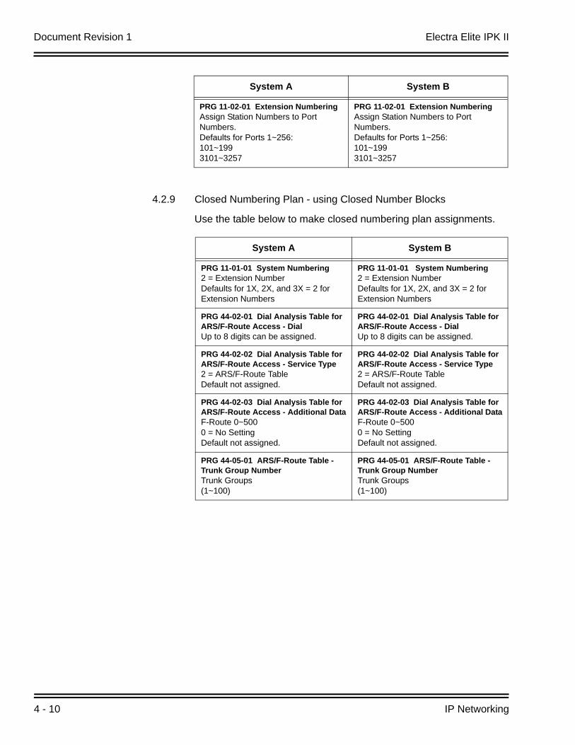
Document Revision 1 Electra Elite IPK II
4 - 10 IP Networking
4.2.9 Closed Numbering Plan - using Closed Number Blocks
Use the table below to make closed numbering plan assignments.
PRG 11-02-01 Extension NumberingAssign Station Numbers to Port Numbers.Defaults for Ports 1~256:101~1993101~3257
PRG 11-02-01 Extension NumberingAssign Station Numbers to Port Numbers.Defaults for Ports 1~256:101~1993101~3257
System A System B
PRG 11-01-01 System Numbering2 = Extension NumberDefaults for 1X, 2X, and 3X = 2 for Extension Numbers
PRG 11-01-01 System Numbering2 = Extension NumberDefaults for 1X, 2X, and 3X = 2 for Extension Numbers
PRG 44-02-01 Dial Analysis Table for ARS/F-Route Access - DialUp to 8 digits can be assigned.
PRG 44-02-01 Dial Analysis Table for ARS/F-Route Access - DialUp to 8 digits can be assigned.
PRG 44-02-02 Dial Analysis Table for ARS/F-Route Access - Service Type2 = ARS/F-Route TableDefault not assigned.
PRG 44-02-02 Dial Analysis Table for ARS/F-Route Access - Service Type2 = ARS/F-Route TableDefault not assigned.
PRG 44-02-03 Dial Analysis Table for ARS/F-Route Access - Additional DataF-Route 0~5000 = No SettingDefault not assigned.
PRG 44-02-03 Dial Analysis Table for ARS/F-Route Access - Additional DataF-Route 0~5000 = No SettingDefault not assigned.
PRG 44-05-01 ARS/F-Route Table - Trunk Group NumberTrunk Groups(1~100)
PRG 44-05-01 ARS/F-Route Table - Trunk Group NumberTrunk Groups(1~100)
System A System B
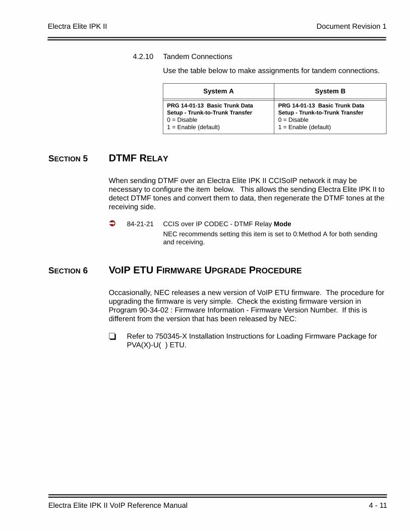
Electra Elite IPK II Document Revision 1
Electra Elite IPK II VoIP Reference Manual 4 - 11
4.2.10 Tandem Connections
Use the table below to make assignments for tandem connections.
SECTION 5 DTMF RELAY
When sending DTMF over an Electra Elite IPK II CCISoIP network it may be necessary to configure the item below. This allows the sending Electra Elite IPK II to detect DTMF tones and convert them to data, then regenerate the DTMF tones at the receiving side.
84-21-21 CCIS over IP CODEC - DTMF Relay ModeNEC recommends setting this item is set to 0:Method A for both sending and receiving.
SECTION 6 VOIP ETU FIRMWARE UPGRADE PROCEDURE
Occasionally, NEC releases a new version of VoIP ETU firmware. The procedure for upgrading the firmware is very simple. Check the existing firmware version in Program 90-34-02 : Firmware Information - Firmware Version Number. If this is different from the version that has been released by NEC:
Refer to 750345-X Installation Instructions for Loading Firmware Package for PVA(X)-U( ) ETU.
System A System B
PRG 14-01-13 Basic Trunk Data Setup - Trunk-to-Trunk Transfer0 = Disable1 = Enable (default)
PRG 14-01-13 Basic Trunk Data Setup - Trunk-to-Trunk Transfer0 = Disable1 = Enable (default)

Document Revision 1 Electra Elite IPK II
4 - 12 IP Networking
THIS PAGE INTENTIONALLY LEFT BLANK

Electra Elite IPK II VoIP Reference Manual 5 - 1
Pro
gra
mm
ing
5Programming
SECTION 1 BEFORE YOU START PROGRAMMING
This chapter provides you with detailed information about the Electra Elite IPK II program blocks that may be required to connect the Electra Elite IPK II to a data network and to configure the VoIP ETU function. The configuration and programming examples, found in the earlier chapters, can be useful as a reference when programming the data.
When using this chapter, note that the information on each program is subdivided into the following headings:
Description describes what the program options control. The Default Settings for each program are also included. When you first install the system, it uses the Default Setting for all programs. Along with the Description are the Conditions which describe any limits or special considerations that may apply to the program.
The reverse type (white on black) just beneath the Description heading is the program’s access level. You can only use the program if your access level meets or exceeds the level the program requires. Refer to Section 2 How to Enter Programming Mode on page 5-2 for a list of the system access levels and passwords.
Feature Cross Reference provides you with a table of all the features affected by the program. You will want to keep the referenced features in mind when you change a program. Customizing a feature may have an effect on another feature that you did not intend.
Telephone Programming Instructions shows how to enter the program data into system memory. For example:
1. Enter the programming mode.
2. 15-07-01
15-07-01 TELKY01 = *01 ← →
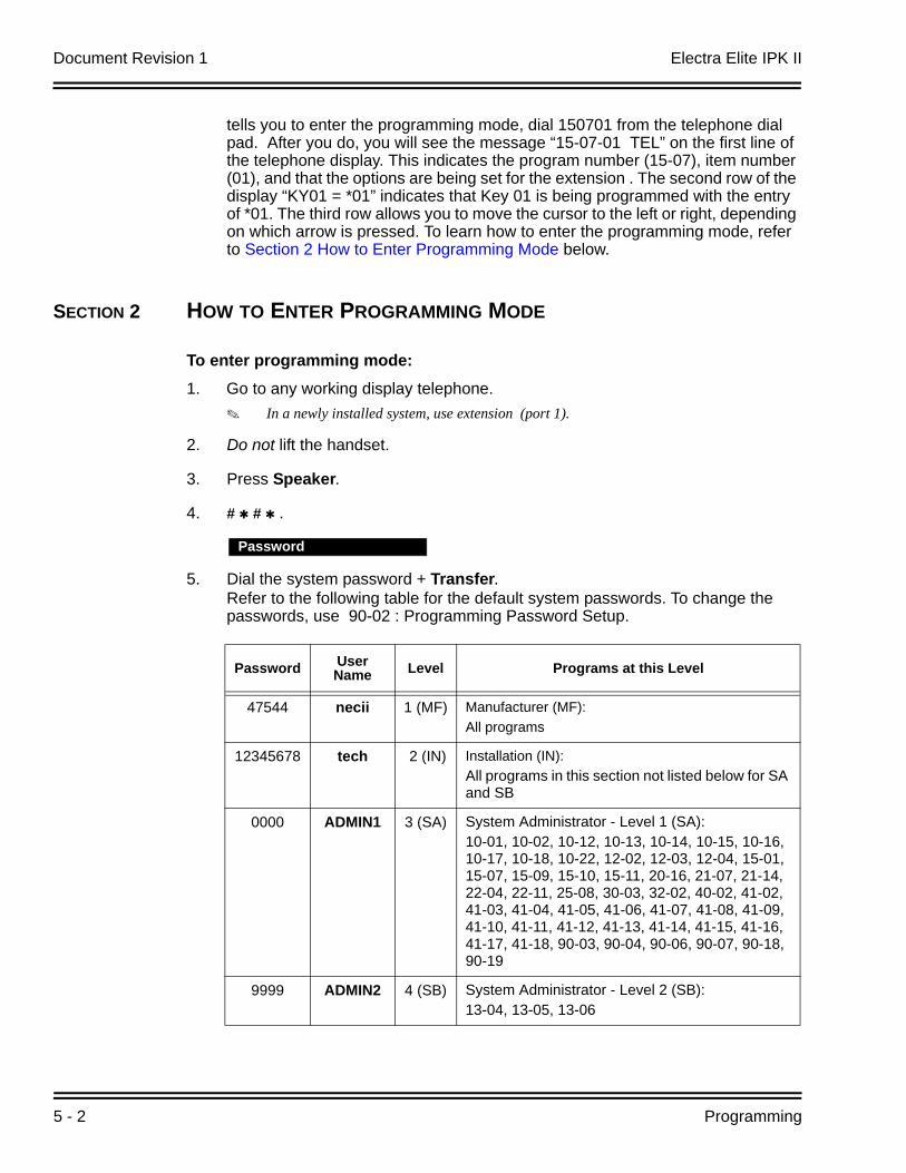
Document Revision 1 Electra Elite IPK II
5 - 2 Programming
tells you to enter the programming mode, dial 150701 from the telephone dial pad. After you do, you will see the message “15-07-01 TEL” on the first line of the telephone display. This indicates the program number (15-07), item number (01), and that the options are being set for the extension . The second row of the display “KY01 = *01” indicates that Key 01 is being programmed with the entry of *01. The third row allows you to move the cursor to the left or right, depending on which arrow is pressed. To learn how to enter the programming mode, refer to Section 2 How to Enter Programming Mode below.
SECTION 2 HOW TO ENTER PROGRAMMING MODE
To enter programming mode:1. Go to any working display telephone.
In a newly installed system, use extension (port 1).
2. Do not lift the handset.
3. Press Speaker.
4. # # .
5. Dial the system password + Transfer.Refer to the following table for the default system passwords. To change the passwords, use 90-02 : Programming Password Setup.
Password
Password User Name Level Programs at this Level
47544 necii 1 (MF) Manufacturer (MF): All programs
12345678 tech 2 (IN) Installation (IN): All programs in this section not listed below for SA and SB
0000 ADMIN1 3 (SA) System Administrator - Level 1 (SA): 10-01, 10-02, 10-12, 10-13, 10-14, 10-15, 10-16, 10-17, 10-18, 10-22, 12-02, 12-03, 12-04, 15-01, 15-07, 15-09, 15-10, 15-11, 20-16, 21-07, 21-14, 22-04, 22-11, 25-08, 30-03, 32-02, 40-02, 41-02, 41-03, 41-04, 41-05, 41-06, 41-07, 41-08, 41-09, 41-10, 41-11, 41-12, 41-13, 41-14, 41-15, 41-16, 41-17, 41-18, 90-03, 90-04, 90-06, 90-07, 90-18, 90-19
9999 ADMIN2 4 (SB) System Administrator - Level 2 (SB): 13-04, 13-05, 13-06

Electra Elite IPK II Document Revision 1
Electra Elite IPK II VoIP Reference Manual 5 - 3
SECTION 3 HOW TO EXIT PROGRAMMING MODE
To exit the programming mode: When you are done programming, you must be out of a program’s options to exit (pressing the Answer key will exit the program’s option).
1. Press the Answer key to exit the program’s options, if needed.
2. Press the Speaker key. If changes were to the system programming, "Saving System Data" is displayed.
3. The display shows "Complete Data Save" when completed and exits the telephone to an idle mode.
To save a customer’s database, a blank Compact Flash (CF) is required. Insert the CF into the CPUII and, using Program 90-03, save the software to the Compact Flash. (Program 90-04 is used to reload the customer data if necessary.) Note that a Compact Flash can only hold one customer database. Each database to be saved requires a separate card.
SECTION 4 USING KEYS TO MOVE AROUND IN THE PROGRAMS
Once you enter the programming mode, use the keys in the following chart to enter data, edit data and move around in the menus.
Program ModeBase Service OP1 OP2
Table 5-1 Keys for Entering Data
Keys for Entering Data
Use this key... When you want to...
0~9 and Enter data into a program.
Transfer Complete the programming step you just made (e.g., pressing Enter on a PC keyboard). When a program entry displays, press Transfer to bypass the entry without changing it.
Conf Delete the entry to the left (e.g., pressing Backspace on a PC keyboard).
Hold Delete or clear all characters to the right of the cursor.
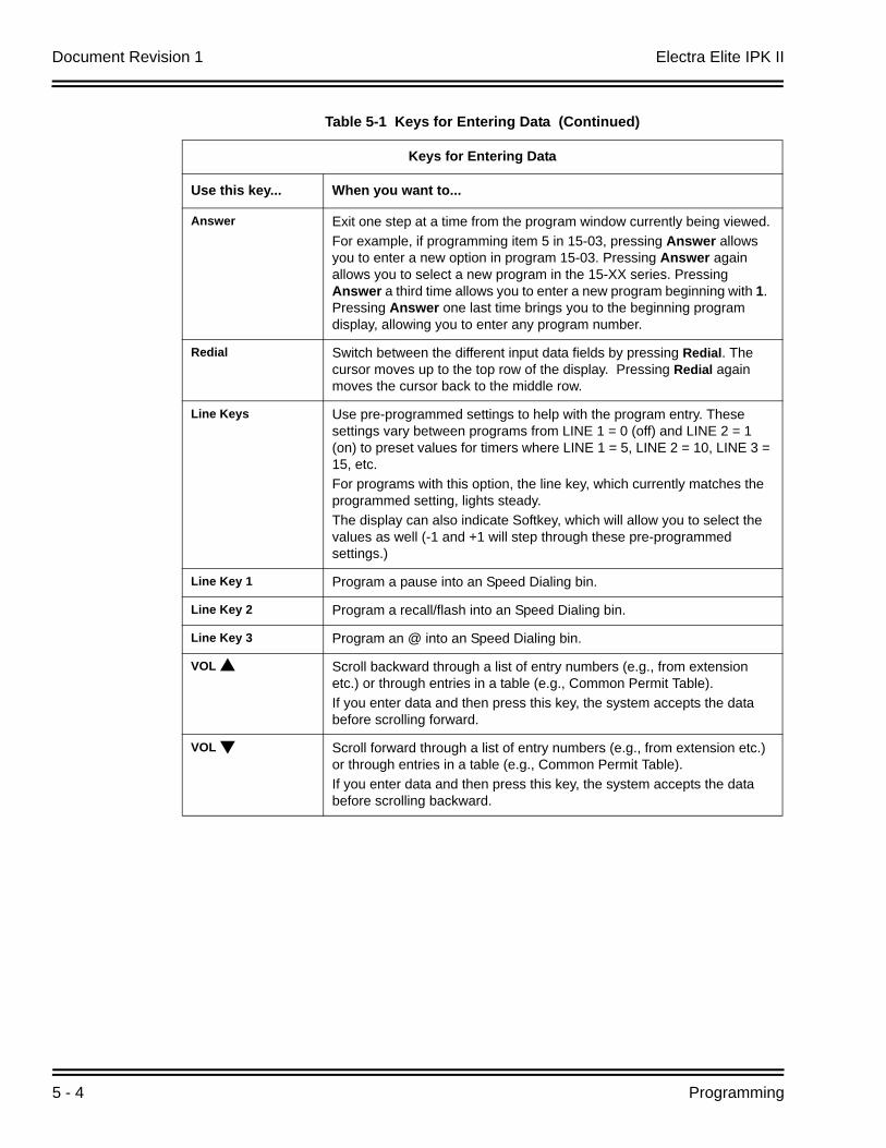
Document Revision 1 Electra Elite IPK II
5 - 4 Programming
Answer Exit one step at a time from the program window currently being viewed. For example, if programming item 5 in 15-03, pressing Answer allows you to enter a new option in program 15-03. Pressing Answer again allows you to select a new program in the 15-XX series. Pressing Answer a third time allows you to enter a new program beginning with 1. Pressing Answer one last time brings you to the beginning program display, allowing you to enter any program number.
Redial Switch between the different input data fields by pressing Redial. The cursor moves up to the top row of the display. Pressing Redial again moves the cursor back to the middle row.
Line Keys Use pre-programmed settings to help with the program entry. These settings vary between programs from LINE 1 = 0 (off) and LINE 2 = 1 (on) to preset values for timers where LINE 1 = 5, LINE 2 = 10, LINE 3 = 15, etc.For programs with this option, the line key, which currently matches the programmed setting, lights steady.The display can also indicate Softkey, which will allow you to select the values as well (-1 and +1 will step through these pre-programmed settings.)
Line Key 1 Program a pause into an Speed Dialing bin.
Line Key 2 Program a recall/flash into an Speed Dialing bin.
Line Key 3 Program an @ into an Speed Dialing bin.
VOL Scroll backward through a list of entry numbers (e.g., from extension etc.) or through entries in a table (e.g., Common Permit Table). If you enter data and then press this key, the system accepts the data before scrolling forward.
VOL Scroll forward through a list of entry numbers (e.g., from extension etc.) or through entries in a table (e.g., Common Permit Table).If you enter data and then press this key, the system accepts the data before scrolling backward.
Table 5-1 Keys for Entering Data (Continued)
Keys for Entering Data
Use this key... When you want to...
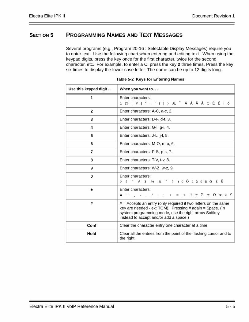
Electra Elite IPK II Document Revision 1
Electra Elite IPK II VoIP Reference Manual 5 - 5
SECTION 5 PROGRAMMING NAMES AND TEXT MESSAGES
Several programs (e.g., Program 20-16 : Selectable Display Messages) require you to enter text. Use the following chart when entering and editing text. When using the keypad digits, press the key once for the first character, twice for the second character, etc. For example, to enter a C, press the key 2 three times. Press the key six times to display the lower case letter. The name can be up to 12 digits long.
Table 5-2 Keys for Entering Names
Use this keypad digit . . . When you want to. . .
1 Enter characters:1 @ [ ¥ ] ^ _ ` { | } Æ ¨ Á À Â Ã Ç É Ê ì ó
2 Enter characters: A-C, a-c, 2.
3 Enter characters: D-F, d-f, 3.
4 Enter characters: G-I, g-i, 4.
5 Enter characters: J-L, j-l, 5.
6 Enter characters: M-O, m-o, 6.
7 Enter characters: P-S, p-s, 7.
8 Enter characters: T-V, t-v, 8.
9 Enter characters: W-Z, w-z, 9.
0 Enter characters:0 ! “ # $ % & ’ ( ) ô Õ ú ä ö ü α ε θ
Enter characters: + , - . / : ; < = > ? B E σ S ∞ ¢ £
# # = Accepts an entry (only required if two letters on the same key are needed - ex: TOM). Pressing # again = Space. (In system programming mode, use the right arrow Softkey instead to accept and/or add a space.)
Conf Clear the character entry one character at a time.
Hold Clear all the entries from the point of the flashing cursor and to the right.
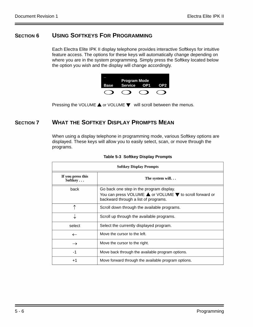
Document Revision 1 Electra Elite IPK II
5 - 6 Programming
SECTION 6 USING SOFTKEYS FOR PROGRAMMING
Each Electra Elite IPK II display telephone provides interactive Softkeys for intuitive feature access. The options for these keys will automatically change depending on where you are in the system programming. Simply press the Softkey located below the option you wish and the display will change accordingly.
Pressing the VOLUME or VOLUME will scroll between the menus.
SECTION 7 WHAT THE SOFTKEY DISPLAY PROMPTS MEAN
When using a display telephone in programming mode, various Softkey options are displayed. These keys will allow you to easily select, scan, or move through the programs.
_Program Mode
Base Service OP1 OP2
Table 5-3 Softkey Display Prompts
Softkey Display Prompts
If you press this Softkey . . . The system will. . .
back Go back one step in the program display.You can press VOLUME or VOLUME to scroll forward or backward through a list of programs.
↑ Scroll down through the available programs.
↓ Scroll up through the available programs.
select Select the currently displayed program.
← Move the cursor to the left.
→ Move the cursor to the right.
-1 Move back through the available program options.
+1 Move forward through the available program options.
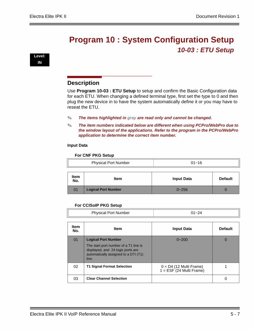
Electra Elite IPK II Document Revision 1
Electra Elite IPK II VoIP Reference Manual 5 - 7
DescriptionUse Program 10-03 : ETU Setup to setup and confirm the Basic Configuration data for each ETU. When changing a defined terminal type, first set the type to 0 and then plug the new device in to have the system automatically define it or you may have to reseat the ETU.
The items highlighted in gray are read only and cannot be changed.
The item numbers indicated below are different when using PCPro/WebPro due to the window layout of the applications. Refer to the program in the PCPro/WebPro application to determine the correct item number.
Input Data
For CNF PKG Setup
For CCISoIP PKG Setup
Program 10 : System Configuration Setup10-03 : ETU Setup
Level:IN
Physical Port Number 01~16
Item No. Item Input Data Default
01 Logical Port Number 0~256 0
Physical Port Number 01~24
Item No. Item Input Data Default
01 Logical Port NumberThe start port number of a T1 line is displayed, and 24 logic ports are automatically assigned to a DTI (T1) line.
0~200 0
02 T1 Signal Format Selection 0 = D4 (12 Multi Frame)1 = ESF (24 Multi Frame)
1
03 Clear Channel Selection 0
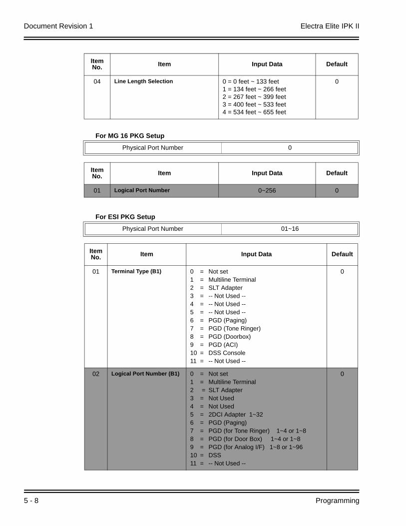
Document Revision 1 Electra Elite IPK II
5 - 8 Programming
For MG 16 PKG Setup
04 Line Length Selection 0 = 0 feet ~ 133 feet1 = 134 feet ~ 266 feet2 = 267 feet ~ 399 feet3 = 400 feet ~ 533 feet4 = 534 feet ~ 655 feet
0
Physical Port Number 0
Item No. Item Input Data Default
01 Logical Port Number 0~256 0
For ESI PKG Setup
Physical Port Number 01~16
Item No. Item Input Data Default
01 Terminal Type (B1) 0 = Not set1 = Multiline Terminal2 = SLT Adapter3 = -- Not Used --4 = -- Not Used --5 = -- Not Used --6 = PGD (Paging)7 = PGD (Tone Ringer)8 = PGD (Doorbox)9 = PGD (ACI)10 = DSS Console11 = -- Not Used --
0
02 Logical Port Number (B1) 0 = Not set1 = Multiline Terminal2 = SLT Adapter3 = Not Used4 = Not Used5 = 2DCI Adapter 1~326 = PGD (Paging)7 = PGD (for Tone Ringer) 1~4 or 1~8 8 = PGD (for Door Box) 1~4 or 1~89 = PGD (for Analog I/F) 1~8 or 1~9610 = DSS11 = -- Not Used --
0
Item No. Item Input Data Default
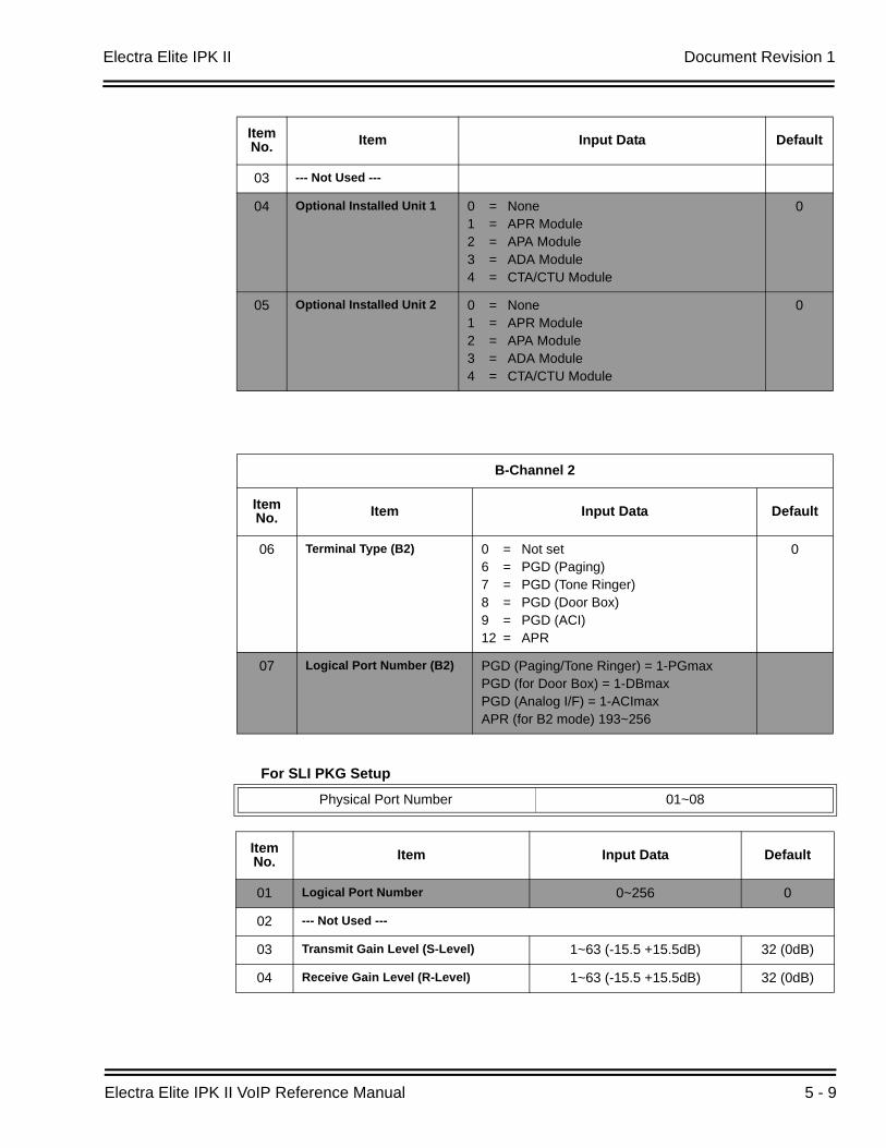
Electra Elite IPK II Document Revision 1
Electra Elite IPK II VoIP Reference Manual 5 - 9
For SLI PKG Setup
03 --- Not Used ---
04 Optional Installed Unit 1 0 = None1 = APR Module2 = APA Module3 = ADA Module4 = CTA/CTU Module
0
05 Optional Installed Unit 2 0 = None1 = APR Module2 = APA Module3 = ADA Module4 = CTA/CTU Module
0
B-Channel 2
Item No. Item Input Data Default
06 Terminal Type (B2) 0 = Not set6 = PGD (Paging)7 = PGD (Tone Ringer)8 = PGD (Door Box)9 = PGD (ACI)12 = APR
0
07 Logical Port Number (B2) PGD (Paging/Tone Ringer) = 1-PGmaxPGD (for Door Box) = 1-DBmaxPGD (Analog I/F) = 1-ACImaxAPR (for B2 mode) 193~256
Physical Port Number 01~08
Item No. Item Input Data Default
01 Logical Port Number 0~256 0
02 --- Not Used ---
03 Transmit Gain Level (S-Level) 1~63 (-15.5 +15.5dB) 32 (0dB)
04 Receive Gain Level (R-Level) 1~63 (-15.5 +15.5dB) 32 (0dB)
Item No. Item Input Data Default
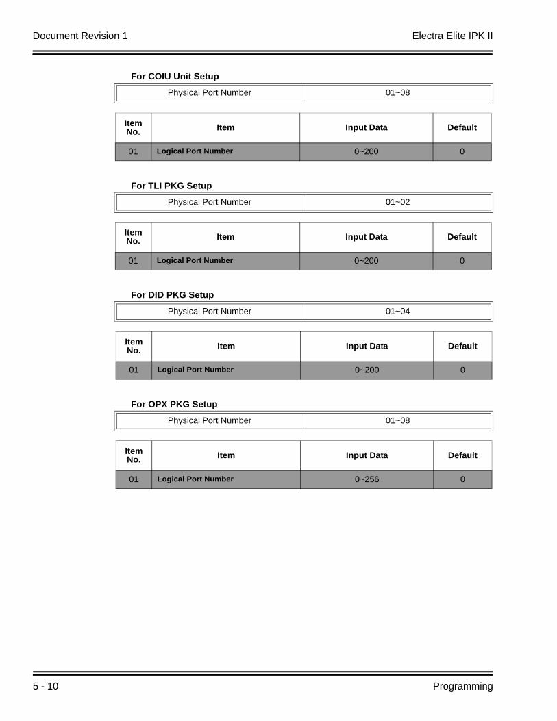
Document Revision 1 Electra Elite IPK II
5 - 10 Programming
For COIU Unit Setup
For TLI PKG Setup
For DID PKG Setup
For OPX PKG Setup
Physical Port Number 01~08
Item No. Item Input Data Default
01 Logical Port Number 0~200 0
Physical Port Number 01~02
Item No. Item Input Data Default
01 Logical Port Number 0~200 0
Physical Port Number 01~04
Item No. Item Input Data Default
01 Logical Port Number 0~200 0
Physical Port Number 01~08
Item No. Item Input Data Default
01 Logical Port Number 0~256 0

Electra Elite IPK II Document Revision 1
Electra Elite IPK II VoIP Reference Manual 5 - 11
For BRI PKG Setup
ISDN Line Number 01~08
Item No Item Input Data Default
01 --- Not Used ---
02 Logical Port Number
The starting port number of a BRI line is displayed. Two logic ports are automatically assigned to a BRI line.
0 = Net Set1 = For T-Bus (1~200)2 = For S-Bus (1~256)
0
03 Connection Type 0 = Point-to-Multipoint (not available for Networking)
1 = Point-to-Point
0
04 Layer 3 Timer Type
Each timer value of Layer 3 is set up for every type using Program 81-06 (T-Bus)
1~5 1
05 CLIP Information AnnouncementBased on this setting, the system includes a Presentation Allowed (1) or Presentation Restricted (0) in the Setup message to allow or deny the Calling Party Number. Program 15-01-04 must also be set to 1 if this option is enabled.
0 = Disable1 = Enable
1
06 --- Not Used ---
07 --- Not Used ---
08 Dial Sending Mode 0 = Enblock Sending1 = Overlap Sending
1
09 Dial Information Element(Only when Dialing Sending Mode (10-03-08) is set for 1 (Overlap Sending)
0 = Keypad Facility1 = Called Party Number
10 --- Not Used ---
11 --- Not Used ---
12 --- Not Used ---
13 --- Not Used ---
14 --- Not Used ---
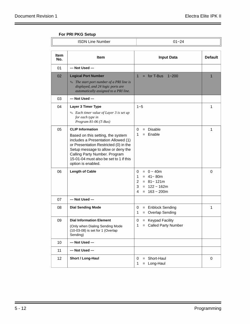
Document Revision 1 Electra Elite IPK II
5 - 12 Programming
For PRI PKG Setup
ISDN Line Number 01~24
Item No. Item Input Data Default
01 --- Not Used ---
02 Logical Port Number
The start port number of a PRI line is displayed, and 24 logic ports are automatically assigned to a PRI line.
1 = for T-Bus 1~200 1
03 --- Not Used ---
04 Layer 3 Timer Type
Each timer value of Layer 3 is set up for each type in Program 81-06 (T-Bus)
1~5 1
05 CLIP Information
Based on this setting, the system includes a Presentation Allowed (1) or Presentation Restricted (0) in the Setup message to allow or deny the Calling Party Number. Program 15-01-04 must also be set to 1 if this option is enabled.
0 = Disable1 = Enable
1
06 Length of Cable 0 = 0 ~ 40m1 = 41~ 80m2 = 81~ 121m3 = 122 ~ 162m4 = 163 ~ 200m
0
07 --- Not Used ---
08 Dial Sending Mode 0 = Enblock Sending1 = Overlap Sending
1
09 Dial Information Element(Only when Dialing Sending Mode (10-03-08) is set for 1 (Overlap Sending)
0 = Keypad Facility1 = Called Party Number
10 --- Not Used ---
11 --- Not Used ---
12 Short / Long-Haul 0 = Short-Haul1 = Long-Haul
0
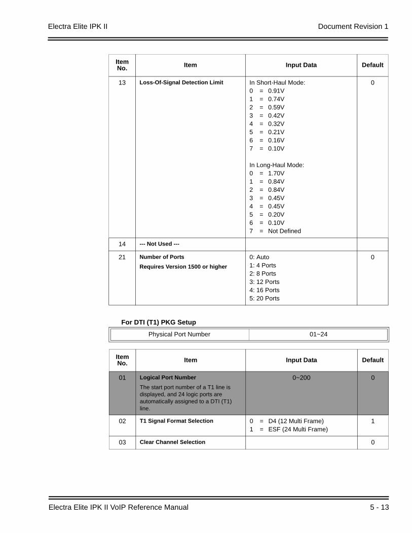
Electra Elite IPK II Document Revision 1
Electra Elite IPK II VoIP Reference Manual 5 - 13
For DTI (T1) PKG Setup
13 Loss-Of-Signal Detection Limit In Short-Haul Mode:0 = 0.91V1 = 0.74V2 = 0.59V3 = 0.42V4 = 0.32V5 = 0.21V6 = 0.16V7 = 0.10V
In Long-Haul Mode:0 = 1.70V1 = 0.84V2 = 0.84V3 = 0.45V4 = 0.45V5 = 0.20V6 = 0.10V7 = Not Defined
0
14 --- Not Used ---
21 Number of PortsRequires Version 1500 or higher
0: Auto1: 4 Ports2: 8 Ports3: 12 Ports4: 16 Ports5: 20 Ports
0
Physical Port Number 01~24
Item No. Item Input Data Default
01 Logical Port NumberThe start port number of a T1 line is displayed, and 24 logic ports are automatically assigned to a DTI (T1) line.
0~200 0
02 T1 Signal Format Selection 0 = D4 (12 Multi Frame)1 = ESF (24 Multi Frame)
1
03 Clear Channel Selection 0
Item No. Item Input Data Default
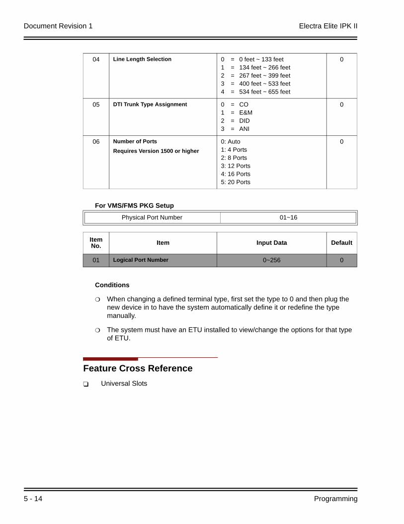
Document Revision 1 Electra Elite IPK II
5 - 14 Programming
For VMS/FMS PKG Setup
Conditions
When changing a defined terminal type, first set the type to 0 and then plug the new device in to have the system automatically define it or redefine the type manually.
The system must have an ETU installed to view/change the options for that type of ETU.
Feature Cross ReferenceUniversal Slots
04 Line Length Selection 0 = 0 feet ~ 133 feet1 = 134 feet ~ 266 feet2 = 267 feet ~ 399 feet3 = 400 feet ~ 533 feet4 = 534 feet ~ 655 feet
0
05 DTI Trunk Type Assignment 0 = CO1 = E&M2 = DID3 = ANI
0
06 Number of PortsRequires Version 1500 or higher
0: Auto1: 4 Ports2: 8 Ports3: 12 Ports4: 16 Ports5: 20 Ports
0
Physical Port Number 01~16
Item No. Item Input Data Default
01 Logical Port Number 0~256 0
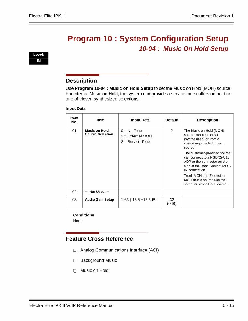
Electra Elite IPK II Document Revision 1
Electra Elite IPK II VoIP Reference Manual 5 - 15
DescriptionUse Program 10-04 : Music on Hold Setup to set the Music on Hold (MOH) source. For internal Music on Hold, the system can provide a service tone callers on hold or one of eleven synthesized selections.
ConditionsNone
Feature Cross Reference
Analog Communications Interface (ACI)
Background Music
Music on Hold
Program 10 : System Configuration Setup10-04 : Music On Hold Setup
Level:IN
Input Data
Item No. Item Input Data Default Description
01 Music on Hold Source Selection
0 = No Tone1 = External MOH2 = Service Tone
2 The Music on Hold (MOH) source can be internal (synthesized) or from a customer-provided music source.The customer-provided source can connect to a PGD(2)-U10 ADP or the connector on the side of the Base Cabinet MOH/IN connection.Trunk MOH and Extension MOH music source use the same Music on Hold source.
02 --- Not Used ---
03 Audio Gain Setup 1-63 (-15.5 +15.5dB) 32 (0dB)
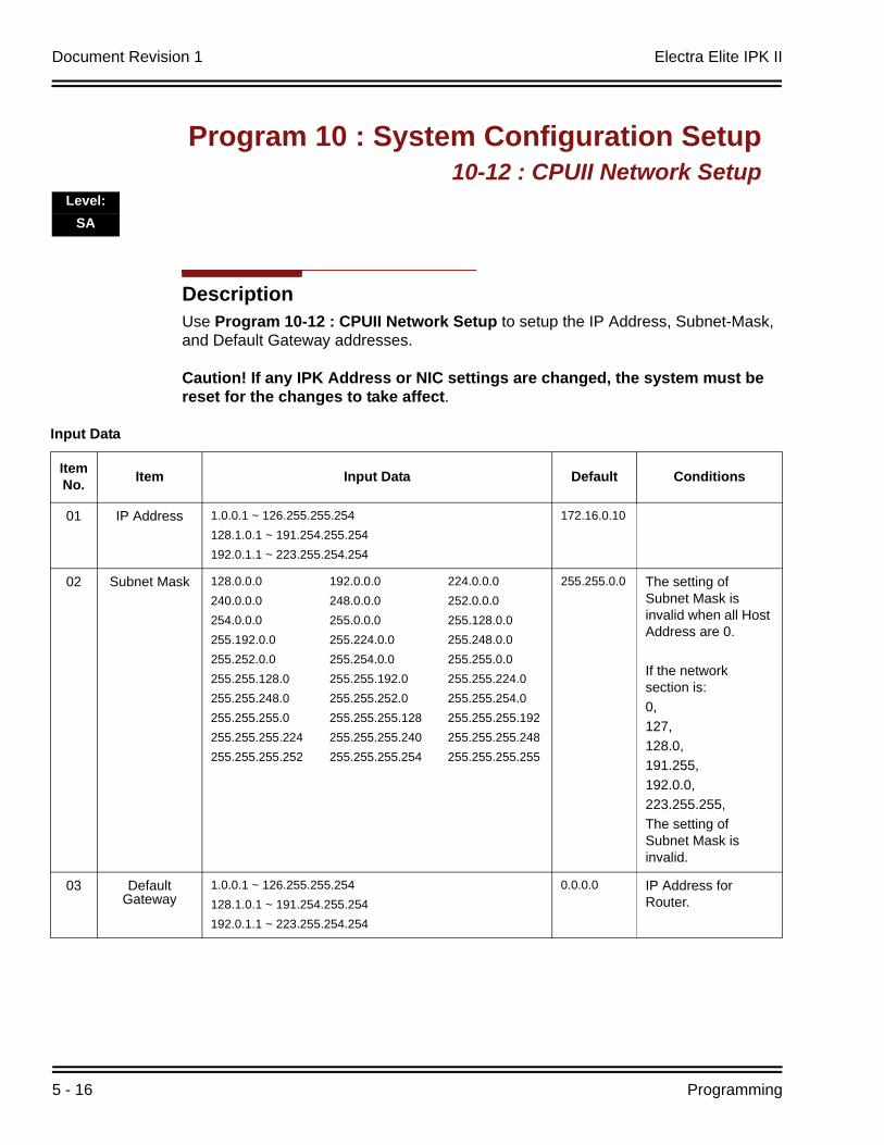
Document Revision 1 Electra Elite IPK II
5 - 16 Programming
DescriptionUse Program 10-12 : CPUII Network Setup to setup the IP Address, Subnet-Mask, and Default Gateway addresses.
Caution! If any IPK Address or NIC settings are changed, the system must be reset for the changes to take affect.
Program 10 : System Configuration Setup10-12 : CPUII Network Setup
Level:SA
Input Data
Item No. Item Input Data Default Conditions
01 IP Address 1.0.0.1 ~ 126.255.255.254 128.1.0.1 ~ 191.254.255.254192.0.1.1 ~ 223.255.254.254
172.16.0.10
02 Subnet Mask 128.0.0.0240.0.0.0254.0.0.0255.192.0.0255.252.0.0255.255.128.0255.255.248.0255.255.255.0255.255.255.224255.255.255.252
192.0.0.0248.0.0.0255.0.0.0255.224.0.0255.254.0.0255.255.192.0255.255.252.0255.255.255.128255.255.255.240255.255.255.254
224.0.0.0252.0.0.0255.128.0.0255.248.0.0255.255.0.0255.255.224.0255.255.254.0255.255.255.192255.255.255.248255.255.255.255
255.255.0.0 The setting of Subnet Mask is invalid when all Host Address are 0.
If the network section is:0,127,128.0,191.255,192.0.0,223.255.255,The setting of Subnet Mask is invalid.
03 DefaultGateway
1.0.0.1 ~ 126.255.255.254 128.1.0.1 ~ 191.254.255.254192.0.1.1 ~ 223.255.254.254
0.0.0.0 IP Address for Router.
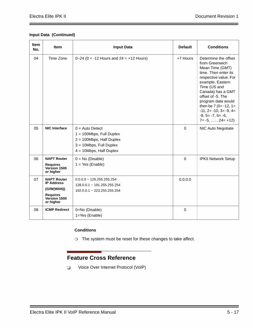
Electra Elite IPK II Document Revision 1
Electra Elite IPK II VoIP Reference Manual 5 - 17
Conditions
The system must be reset for these changes to take affect.
Feature Cross ReferenceVoice Over Internet Protocol (VoIP)
04 Time Zone 0~24 (0 = -12 Hours and 24 = +12 Hours) +7 Hours Determine the offset from Greenwich Mean Time (GMT) time. Then enter its respective value. For example, Eastern Time (US and Canada) has a GMT offset of -5. The program data would then be 7 (0= -12, 1= -11, 2= -10, 3= -9, 4= -8, 5= -7, 6= -6, 7= -5, ……24= +12)
05 NIC Interface 0 = Auto Detect1 = 100Mbps, Full Duplex2 = 100Mbps, Half Duplex3 = 10Mbps, Full Duplex4 = 10Mbps, Half Duplex
0 NIC Auto Negotiate
06 NAPT RouterRequires Version 1500 or higher
0 = No (Disable)1 = Yes (Enable)
0 IPKII Network Setup
07 NAPT Router IP Address(G/W(WAN))Requires Version 1500 or higher
0.0.0.0 ~ 126.255.255.254 128.0.0.1 ~ 191.255.255.254192.0.0.1 ~ 223.255.255.254
0.0.0.0
08 ICMP Redirect 0=No (Disable)1=Yes (Enable)
0
Input Data (Continued)
Item No. Item Input Data Default Conditions
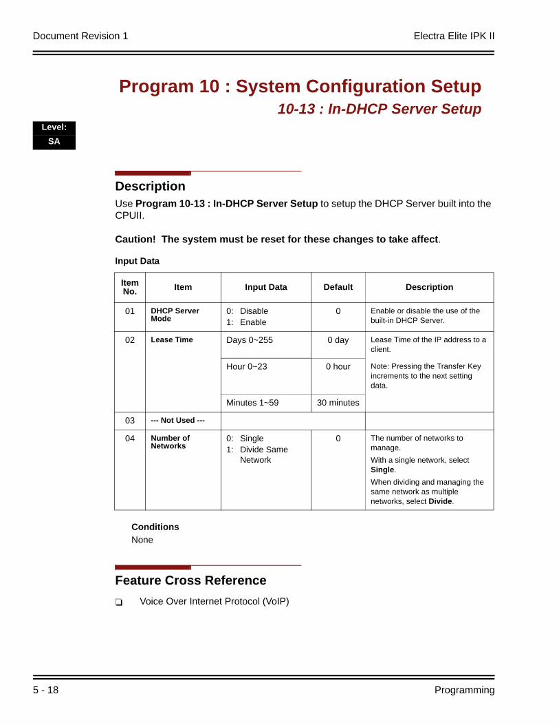
Document Revision 1 Electra Elite IPK II
5 - 18 Programming
DescriptionUse Program 10-13 : In-DHCP Server Setup to setup the DHCP Server built into the CPUII.
Caution! The system must be reset for these changes to take affect.
ConditionsNone
Feature Cross ReferenceVoice Over Internet Protocol (VoIP)
Program 10 : System Configuration Setup10-13 : In-DHCP Server Setup
Level:SA
Input Data
Item No. Item Input Data Default Description
01 DHCP Server Mode
0: Disable1: Enable
0 Enable or disable the use of the built-in DHCP Server.
02 Lease Time Days 0~255 0 day Lease Time of the IP address to a client.
Hour 0~23 0 hour Note: Pressing the Transfer Key increments to the next setting data.
Minutes 1~59 30 minutes
03 --- Not Used ---
04 Number of Networks
0: Single1: Divide Same
Network
0 The number of networks to manage.With a single network, select Single.When dividing and managing the same network as multiple networks, select Divide.
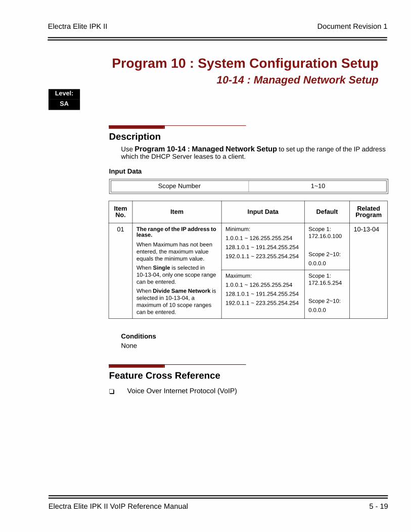
Electra Elite IPK II Document Revision 1
Electra Elite IPK II VoIP Reference Manual 5 - 19
DescriptionUse Program 10-14 : Managed Network Setup to set up the range of the IP address which the DHCP Server leases to a client.
ConditionsNone
Feature Cross ReferenceVoice Over Internet Protocol (VoIP)
Program 10 : System Configuration Setup10-14 : Managed Network Setup
Level:SA
Input Data
Scope Number 1~10
Item No. Item Input Data Default Related
Program
01 The range of the IP address to lease.When Maximum has not been entered, the maximum value equals the minimum value.When Single is selected in 10-13-04, only one scope range can be entered.When Divide Same Network is selected in 10-13-04, a maximum of 10 scope ranges can be entered.
Minimum:1.0.0.1 ~ 126.255.255.254 128.1.0.1 ~ 191.254.255.254192.0.1.1 ~ 223.255.254.254
Scope 1: 172.16.0.100
Scope 2~10:0.0.0.0
10-13-04
Maximum:1.0.0.1 ~ 126.255.255.254 128.1.0.1 ~ 191.254.255.254192.0.1.1 ~ 223.255.254.254
Scope 1: 172.16.5.254
Scope 2~10:0.0.0.0

Document Revision 1 Electra Elite IPK II
5 - 20 Programming
DescriptionUse Program 10-15 : Client Information Setup to set up the client information when the DHCP server needs to assign a fixed IP address to clients.
ConditionsNone
Feature Cross ReferenceVoice Over Internet Protocol (VoIP)
Program 10 : System Configuration Setup10-15 : Client Information Setup
Level:SA
Input Data
Client Number 1~10
Item No. Item Input Data Default
01 The IP address should be assigned out of the scope range set up in Program 10-14.
MAC: 00-00-00-00-00-00FF-FF-FF-FF-FF-FF
00-00-00-00-00-00
IP address1.0.0.1 ~ 126.255.255.254 128.1.0.1 ~ 191.254.255.254192.0.1.1 ~ 223.255.254.254
0.0.0.0
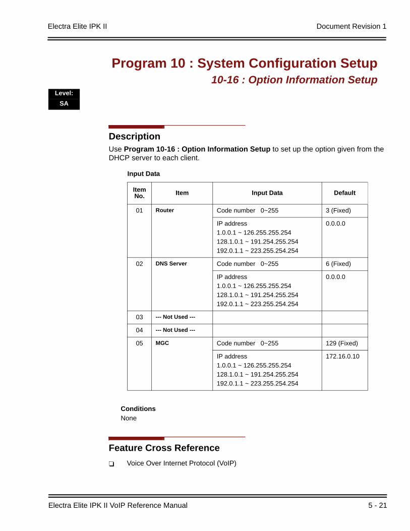
Electra Elite IPK II Document Revision 1
Electra Elite IPK II VoIP Reference Manual 5 - 21
DescriptionUse Program 10-16 : Option Information Setup to set up the option given from the DHCP server to each client.
ConditionsNone
Feature Cross ReferenceVoice Over Internet Protocol (VoIP)
Program 10 : System Configuration Setup10-16 : Option Information Setup
Level:SA
Input Data
Item No. Item Input Data Default
01 Router Code number 0~255 3 (Fixed)
IP address1.0.0.1 ~ 126.255.255.254 128.1.0.1 ~ 191.254.255.254192.0.1.1 ~ 223.255.254.254
0.0.0.0
02 DNS Server Code number 0~255 6 (Fixed)
IP address1.0.0.1 ~ 126.255.255.254 128.1.0.1 ~ 191.254.255.254192.0.1.1 ~ 223.255.254.254
0.0.0.0
03 --- Not Used ---
04 --- Not Used ---
05 MGC Code number 0~255 129 (Fixed)
IP address1.0.0.1 ~ 126.255.255.254 128.1.0.1 ~ 191.254.255.254192.0.1.1 ~ 223.255.254.254
172.16.0.10
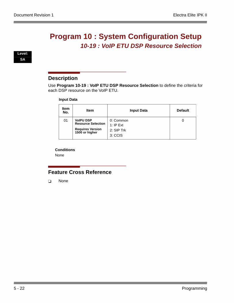
Document Revision 1 Electra Elite IPK II
5 - 22 Programming
DescriptionUse Program 10-19 : VoIP ETU DSP Resource Selection to define the criteria for each DSP resource on the VoIP ETU.
ConditionsNone
Feature Cross ReferenceNone
Program 10 : System Configuration Setup10-19 : VoIP ETU DSP Resource Selection
Level:SA
Input Data
Item No. Item Input Data Default
01 VoIPU DSP Resource SelectionRequires Version 1500 or higher
0: Common1: IP Ext2: SIP Trk3: CCIS
0
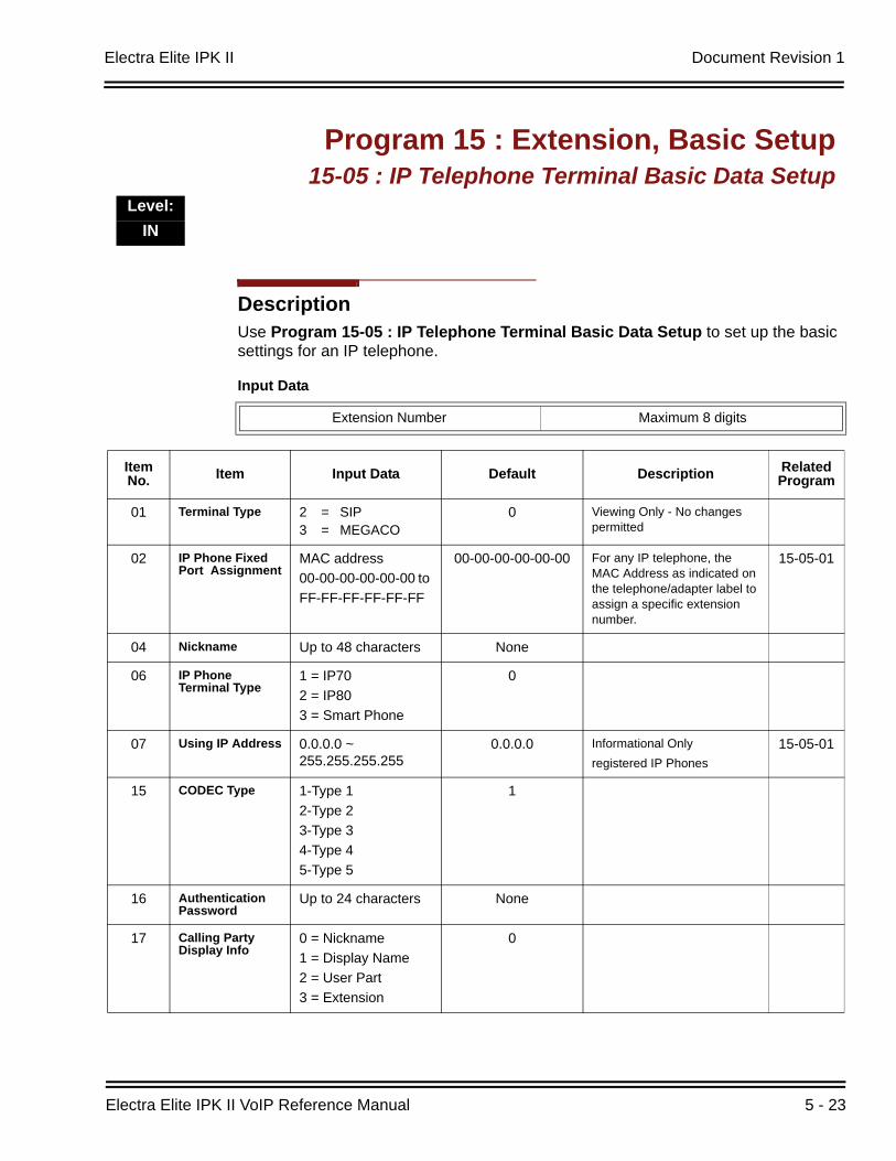
Electra Elite IPK II Document Revision 1
Electra Elite IPK II VoIP Reference Manual 5 - 23
DescriptionUse Program 15-05 : IP Telephone Terminal Basic Data Setup to set up the basic settings for an IP telephone.
Program 15 : Extension, Basic Setup15-05 : IP Telephone Terminal Basic Data Setup
Level:IN
Input Data
Extension Number Maximum 8 digits
Item No. Item Input Data Default Description Related
Program
01 Terminal Type 2 = SIP3 = MEGACO
0 Viewing Only - No changes permitted
02 IP Phone Fixed Port Assignment
MAC address00-00-00-00-00-00 to FF-FF-FF-FF-FF-FF
00-00-00-00-00-00 For any IP telephone, the MAC Address as indicated on the telephone/adapter label to assign a specific extension number.
15-05-01
04 Nickname Up to 48 characters None
06 IP Phone Terminal Type
1 = IP702 = IP803 = Smart Phone
0
07 Using IP Address 0.0.0.0 ~ 255.255.255.255
0.0.0.0 Informational Onlyregistered IP Phones
15-05-01
15 CODEC Type 1-Type 12-Type 23-Type 34-Type 45-Type 5
1
16 Authentication Password
Up to 24 characters None
17 Calling Party Display Info
0 = Nickname1 = Display Name 2 = User Part 3 = Extension
0
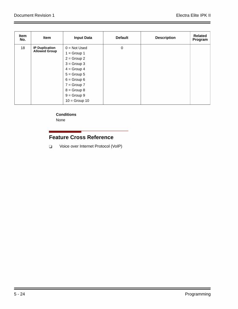
Document Revision 1 Electra Elite IPK II
5 - 24 Programming
ConditionsNone
Feature Cross ReferenceVoice over Internet Protocol (VoIP)
18 IP Duplication Allowed Group
0 = Not Used1 = Group 12 = Group 23 = Group 34 = Group 45 = Group 56 = Group 67 = Group 78 = Group 89 = Group 910 = Group 10
0
Item No. Item Input Data Default Description Related
Program
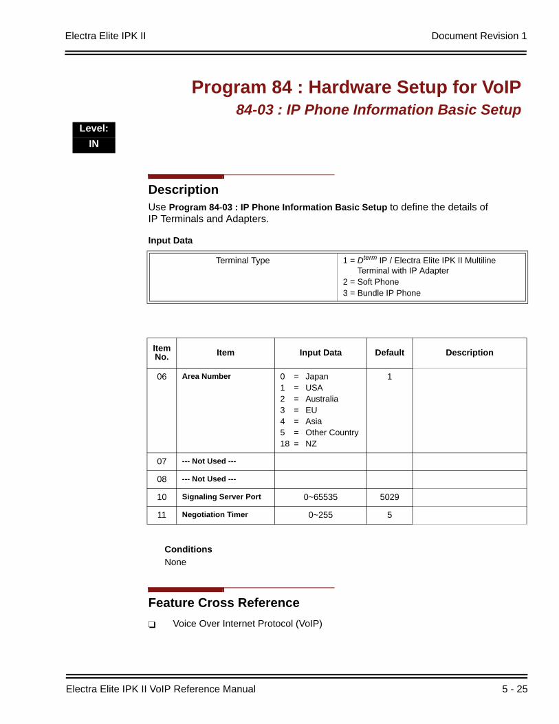
Electra Elite IPK II Document Revision 1
Electra Elite IPK II VoIP Reference Manual 5 - 25
DescriptionUse Program 84-03 : IP Phone Information Basic Setup to define the details of IP Terminals and Adapters.
ConditionsNone
Feature Cross ReferenceVoice Over Internet Protocol (VoIP)
Program 84 : Hardware Setup for VoIP84-03 : IP Phone Information Basic Setup
Level:IN
Input Data
Terminal Type 1 = Dterm IP / Electra Elite IPK II Multiline Terminal with IP Adapter
2 = Soft Phone3 = Bundle IP Phone
Item No. Item Input Data Default Description
06 Area Number 0 = Japan1 = USA2 = Australia3 = EU4 = Asia5 = Other Country18 = NZ
1
07 --- Not Used ---
08 --- Not Used ---
10 Signaling Server Port 0~65535 5029
11 Negotiation Timer 0~255 5
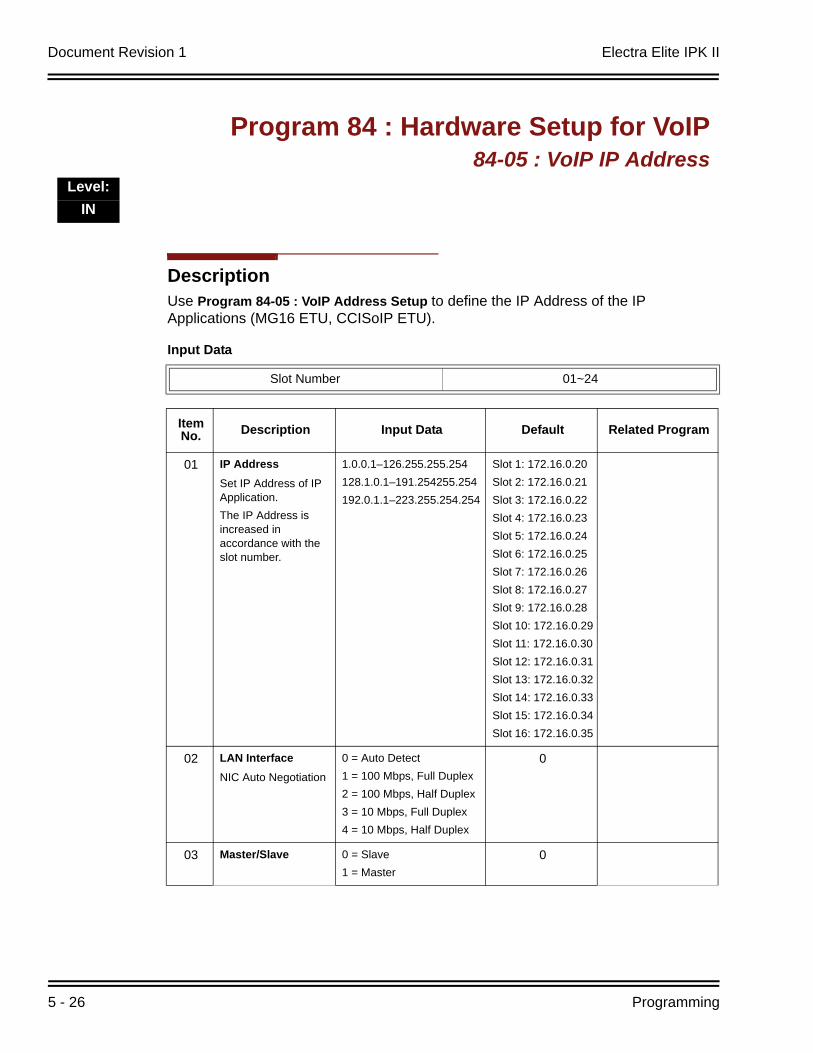
Document Revision 1 Electra Elite IPK II
5 - 26 Programming
DescriptionUse Program 84-05 : VoIP Address Setup to define the IP Address of the IP Applications (MG16 ETU, CCISoIP ETU).
Program 84 : Hardware Setup for VoIP84-05 : VoIP IP Address
Level:IN
Input Data
Slot Number 01~24
ItemNo. Description Input Data Default Related Program
01 IP AddressSet IP Address of IP Application.The IP Address is increased in accordance with the slot number.
1.0.0.1–126.255.255.254 128.1.0.1–191.254255.254192.0.1.1–223.255.254.254
Slot 1: 172.16.0.20Slot 2: 172.16.0.21Slot 3: 172.16.0.22Slot 4: 172.16.0.23Slot 5: 172.16.0.24Slot 6: 172.16.0.25Slot 7: 172.16.0.26Slot 8: 172.16.0.27Slot 9: 172.16.0.28Slot 10: 172.16.0.29Slot 11: 172.16.0.30Slot 12: 172.16.0.31Slot 13: 172.16.0.32Slot 14: 172.16.0.33Slot 15: 172.16.0.34Slot 16: 172.16.0.35
02 LAN InterfaceNIC Auto Negotiation
0 = Auto Detect1 = 100 Mbps, Full Duplex2 = 100 Mbps, Half Duplex3 = 10 Mbps, Full Duplex4 = 10 Mbps, Half Duplex
0
03 Master/Slave 0 = Slave1 = Master
0
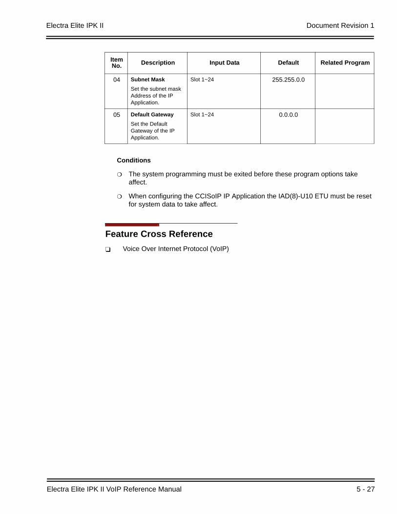
Electra Elite IPK II Document Revision 1
Electra Elite IPK II VoIP Reference Manual 5 - 27
Conditions
The system programming must be exited before these program options take affect.
When configuring the CCISoIP IP Application the IAD(8)-U10 ETU must be reset for system data to take affect.
Feature Cross ReferenceVoice Over Internet Protocol (VoIP)
04 Subnet MaskSet the subnet mask Address of the IP Application.
Slot 1~24 255.255.0.0
05 Default GatewaySet the Default Gateway of the IP Application.
Slot 1~24 0.0.0.0
ItemNo. Description Input Data Default Related Program
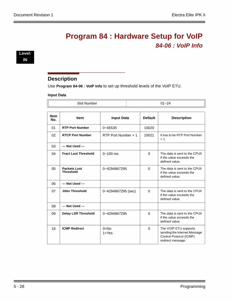
Document Revision 1 Electra Elite IPK II
5 - 28 Programming
DescriptionUse Program 84-06 : VoIP Info to set up threshold levels of the VoIP ETU.
Program 84 : Hardware Setup for VoIP84-06 : VoIP Info
Level:IN
Input Data
Slot Number 01~24
Item No. Item Input Data Default Description
01 RTP Port Number 0~65535 10020
02 RTCP Port Number RTP Port Number + 1 10021 It has to be RTP Port Number + 1.
03 --- Not Used ---
04 Fract Lost Threshold 0~100 ms 0 The data is sent to the CPUII if the value exceeds the defined value.
05 Packets Lost Threshold
0~4294967295 0 The data is sent to the CPUII if the value exceeds the defined value.
06 --- Not Used ---
07 Jitter Threshold 0~4294967295 (sec) 0 The data is sent to the CPUII if the value exceeds the defined value.
08 --- Not Used ---
09 Delay LSR Threshold 0~4294967295 0 The data is sent to the CPUII if the value exceeds the defined value.
16 ICMP Redirect 0=No1=Yes
0 The VOIP ETU supports sending the Internet Message Control Protocol (ICMP) redirect message.
Electra Elite IPK II Document Revision 1
Electra Elite IPK II VoIP Reference Manual 5 - 29
Conditions
The system programming must be exited before these program options take affect.
Feature Cross ReferenceVoice Over Internet Protocol (VoIP)
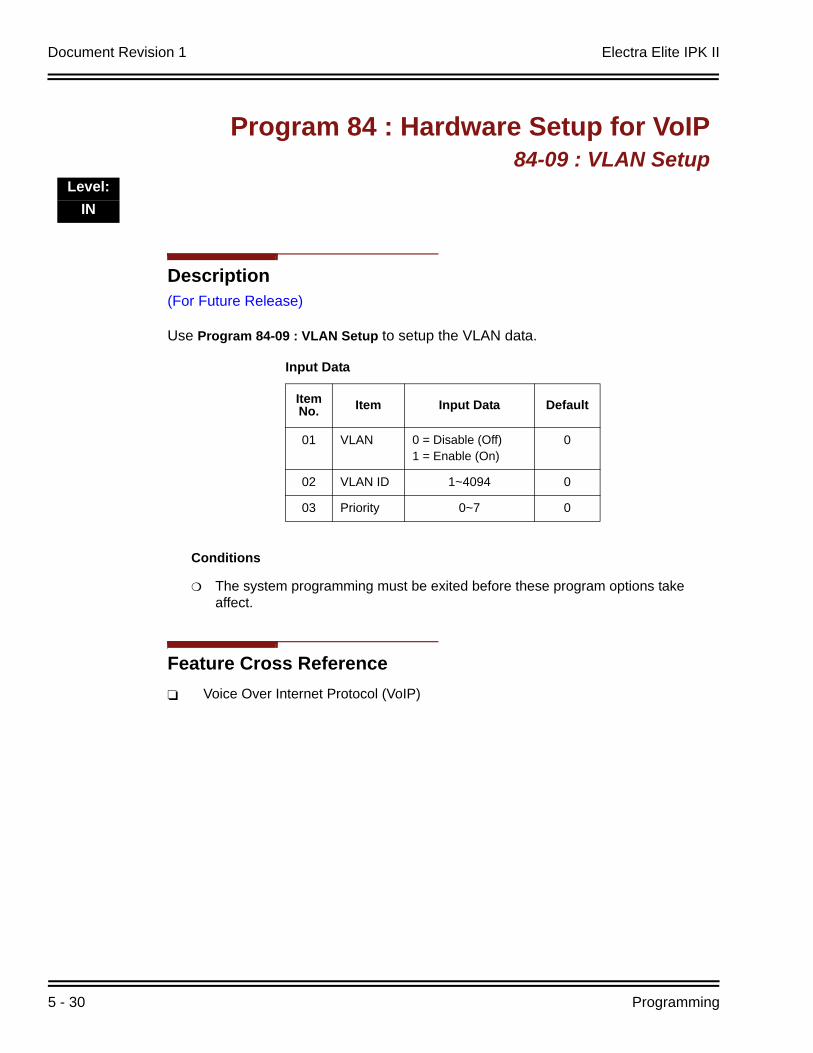
Document Revision 1 Electra Elite IPK II
5 - 30 Programming
Description(For Future Release)
Use Program 84-09 : VLAN Setup to setup the VLAN data.
Conditions
The system programming must be exited before these program options take affect.
Feature Cross ReferenceVoice Over Internet Protocol (VoIP)
Program 84 : Hardware Setup for VoIP84-09 : VLAN Setup
Level:IN
Input Data
Item No. Item Input Data Default
01 VLAN 0 = Disable (Off)1 = Enable (On)
0
02 VLAN ID 1~4094 0
03 Priority 0~7 0
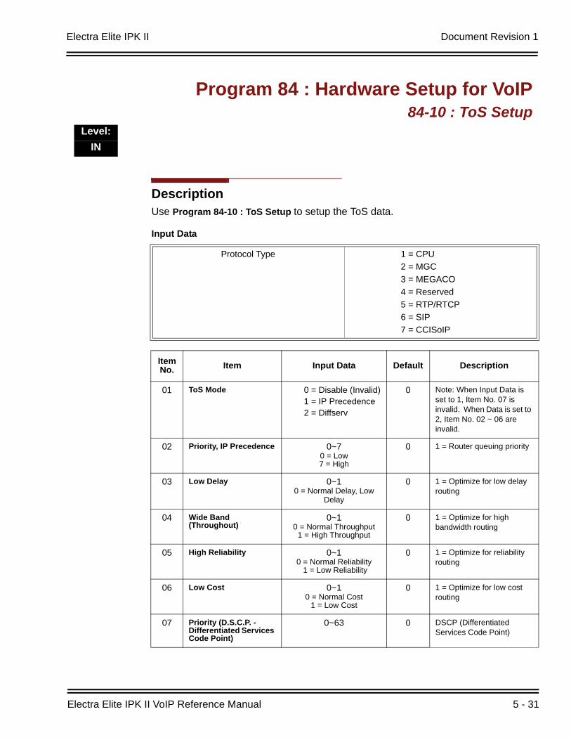
Electra Elite IPK II Document Revision 1
Electra Elite IPK II VoIP Reference Manual 5 - 31
DescriptionUse Program 84-10 : ToS Setup to setup the ToS data.
Program 84 : Hardware Setup for VoIP84-10 : ToS Setup
Level:IN
Input Data
Protocol Type 1 = CPU2 = MGC3 = MEGACO4 = Reserved5 = RTP/RTCP6 = SIP7 = CCISoIP
Item No. Item Input Data Default Description
01 ToS Mode 0 = Disable (Invalid)1 = IP Precedence2 = Diffserv
0 Note: When Input Data is set to 1, Item No. 07 is invalid. When Data is set to 2, Item No. 02 ~ 06 are invalid.
02 Priority, IP Precedence 0~70 = Low7 = High
0 1 = Router queuing priority
03 Low Delay 0~10 = Normal Delay, Low
Delay
0 1 = Optimize for low delay routing
04 Wide Band (Throughout)
0~10 = Normal Throughput
1 = High Throughput
0 1 = Optimize for high bandwidth routing
05 High Reliability 0~10 = Normal Reliability
1 = Low Reliability
0 1 = Optimize for reliability routing
06 Low Cost 0~10 = Normal Cost
1 = Low Cost
0 1 = Optimize for low cost routing
07 Priority (D.S.C.P. -Differentiated Services Code Point)
0~63 0 DSCP (Differentiated Services Code Point)

Document Revision 1 Electra Elite IPK II
5 - 32 Programming
Conditions
The system must be reset for these program options to take affect.
Feature Cross ReferenceVoice Over Internet Protocol (VoIP)
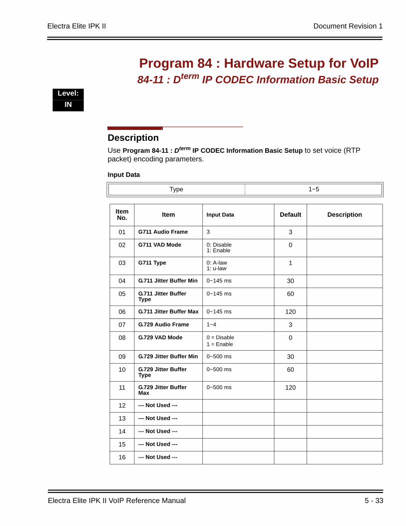
Electra Elite IPK II Document Revision 1
Electra Elite IPK II VoIP Reference Manual 5 - 33
DescriptionUse Program 84-11 : Dterm IP CODEC Information Basic Setup to set voice (RTP packet) encoding parameters.
Program 84 : Hardware Setup for VoIP84-11 : Dterm IP CODEC Information Basic Setup
Level:IN
Input Data
Type 1~5
Item No. Item Input Data Default Description
01 G711 Audio Frame 3 3
02 G711 VAD Mode 0: Disable1: Enable
0
03 G711 Type 0: A-law1: u-law
1
04 G.711 Jitter Buffer Min 0~145 ms 30
05 G.711 Jitter Buffer Type
0~145 ms 60
06 G.711 Jitter Buffer Max 0~145 ms 120
07 G.729 Audio Frame 1~4 3
08 G.729 VAD Mode 0 = Disable1 = Enable
0
09 G.729 Jitter Buffer Min 0~500 ms 30
10 G.729 Jitter Buffer Type
0~500 ms 60
11 G.729 Jitter Buffer Max
0~500 ms 120
12 --- Not Used ---
13 --- Not Used ---
14 --- Not Used ---
15 --- Not Used ---
16 --- Not Used ---
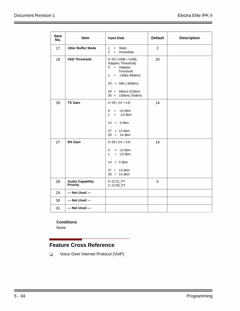
Document Revision 1 Electra Elite IPK II
5 - 34 Programming
ConditionsNone
Feature Cross ReferenceVoice Over Internet Protocol (VoIP)
17 Jitter Buffer Mode 1 = Static2 = Immediate
2
18 VAD Threshold 0~30 (-19db~+10db,Adaptec Threshold)0 = Adaptec
Threshold1 = -19db(-49dbm) :20 = 0db (-30dbm) :29 = 9dbm(-21dbm)30 = 10dbm(-20dbm)
20
26 TX Gain 0~28 (-14~+14)
0 = -14 dbm1 = -13 dbm :14 = 0 dbm :27 = 13 dbm28 = 14 dbm
14
27 RX Gain 0~28 (-14~+14)
0 = -14 dbm1 = -13 dbm :14 = 0 dbm :27 = 13 dbm28 = 14 dbm
14
28 Audio Capability Priority
0: G711_PT2: G729_PT
0
29 --- Not Used ---
30 --- Not Used ---
31 --- Not Used ---
Item No. Item Input Data Default Description
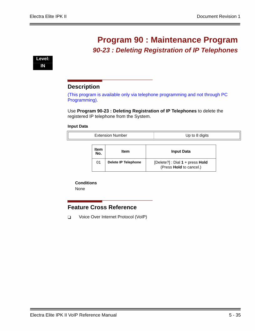
Electra Elite IPK II Document Revision 1
Electra Elite IPK II VoIP Reference Manual 5 - 35
Description(This program is available only via telephone programming and not through PC Programming).
Use Program 90-23 : Deleting Registration of IP Telephones to delete the registered IP telephone from the System.
ConditionsNone
Feature Cross ReferenceVoice Over Internet Protocol (VoIP)
Program 90 : Maintenance Program90-23 : Deleting Registration of IP Telephones
Level:IN
Input Data
Extension Number Up to 8 digits
Item No. Item Input Data
01 Delete IP Telephone [Delete?] : Dial 1 + press Hold(Press Hold to cancel.)

Document Revision 1 Electra Elite IPK II
5 - 36 Programming
DescriptionUse Program 90-34 : Firmware Information to list the package type and firmware ETUs installed in the system.
ConditionsNone
Feature Cross ReferenceNone
Program 90 : Maintenance Program90-34 : Firmware Information
Level:IN
Input Data
Slot No. 1~24
Item No. Item Display Data
01 Pkg Name Pkg Name
02 Firmware Version Number 00.00-0F-FF
Electra Elite IPK II VoIP Reference Manual 6 - 1
Ne
two
rk De
sign
Co
nsid
eratio
ns
6Network Design Considerations
SECTION 1 INTRODUCTION
This chapter explains some of the issues that should be considered when planning an Electra Elite IPK II VoIP installation. It should be noted that this is a generalized explanation and therefore does not discuss vendor-specific issues and solutions. Typically, there are different solutions implemented by different manufacturers.
SECTION 2 QOS
Quality of Service (QoS) is one of the most important factors for VoIP. The term refers to the perceived quality of speech and the methods used to provide good quality speech transmission. There are several factors that affect speech quality, and several mechanisms that can be used to ensure QoS.
This chapter also describes the problems that can occur and some possible solutions. Each network equipment manufacturer (NEC, 3com, Cisco, etc.) will have slightly different methods of implementing QoS and these are not discussed in this document. This chapter provides an overview and explains to classify voice traffic on the Electra Elite IPK II so that the network equipment can impose QoS.
2.1 QoS Definitions
This section lists common definitions used with QoS for VoIP.
Latency (Delay): If at any point the usage on the network exceeds the available bandwidth, the users will experience delay, also know as latency. In more traditional uses of an IP data network, the applications can deal with this latency. If a person is waiting for a web page to download, they will accept a certain amount of wait time. This is not so for voice traffic. Voice is a real time application, which is sensitive to latency. If the end-to-end voice latency becomes too long (250 ms, for example),
Document Revision 1 Electra Elite IPK II
6 - 2 Network Design Considerations
the call quality is usually considered poor. It is also important to remember that packets can get lost. IP is a best effort networking protocol. This means the network tries to get the information there, but there is no guarantee.
Delay is the time required for a signal to traverse the network. In a telephony context, end-to-end delay is the time required for a signal generated at the talker's mouth to reach the listener's ear. Therefore, end-to-end delay is the sum of all the delays at the different network devices and across the network links through which voice traffic passes. Many factors contribute to end-to-end delay, which are covered next.
The buffering, queuing, and switching or routing delay of IP routers primarily determines IP network delay. Specifically, IP network delay is comprised of the following:
Packet Capture DelayPacket capture delay is the time required to receive the entire packet before processing and forwarding it through the router. This delay is determined by the packet length and transmission speed. Using short packets over high-speed networks can easily shorten the delay but potentially decrease network efficiency.
Switching/Routing DelaySwitching/routing delay is the time the router takes to switch the packet. This time is needed to analyze the packet header, check the routing table, and route the packet to the output port. This delay depends on the architecture of the switches/routers and the size of the routing table.
Queuing TimeDue to the statistical multiplexing nature of IP networks and to the asynchronous nature of packet arrivals, some queuing, thus delay, is required at the input and output ports of a packet switch. This delay is a function of the traffic load on a packet switch, the length of the packets and the statistical distribution over the ports. Designing very large router and link capacities can reduce but not completely eliminate this delay.
Jitter Delay variation is the difference in delay exhibited by different packets that are part of the same traffic flow. High frequency delay variation is known as jitter. Jitter is caused primarily by differences in queue wait times for consecutive packets in a flow, and is the most significant issue for QoS. Certain traffic types-especially real-time traffic such as voice, are very intolerant of jitter. Differences in packet arrival times cause choppiness in the voice.
All transport systems exhibit some jitter. As long as jitter falls within defined tolerances, it does not impact service quality. Excessive jitter can be overcome by buffering, but this increases delay, which can cause other problems. With intelligent discard mechanisms, IP telephony/VoIP systems will try to synchronize
Electra Elite IPK II Document Revision 1
Electra Elite IPK II VoIP Reference Manual 6 - 3
a communication flow by selective packet discard, in an effort to avoid the "walkie-talkie" phenomenon caused when two sides of a conversation have significant latency. Electra Elite IPK II incorporates a Jitter Buffer to avoid these problems.
Packet Loss During a voice transmission, loss of multiple bits or packets of stream may cause an audible pop that will become annoying to the user. In a data transmission, loss of a single bit or multiple packets of information is almost never noticed by users. If packet drops become epidemic, then the quality of all transmissions degrades. Packet loss rate must be less than five percent for minimum quality and less than one percent for toll quality.
2.2 Voice Quality Improvements
This section describes various techniques that can be used to improve the voice quality.
Increase available bandwidth:This can sometimes be the most basic solution and the easiest of the solutions. If running a System IP Phone using G.711 with a 30ms fill time over Ethernet, for only one call, 90Kbps of bandwidth is needed. If that same user only has a 64K line, they will not have a decent IP voice call. The user can simply increase the available bandwidth to slightly exceed the 90Kbps requirements and their voice quality dramatically increases. This solution might not be viable if no more bandwidth is available.
Use a different CODEC: The CODEC contains possible compression algorithms to be used on the voice. Lets take the example above again. The user only wants one voice line over a 64Kbps data connection. They also want to maintain their current fill time of 30ms. Change to a G.729. For one line, only 34Kbps is required for a call. This fits well within the 64Kbps of available bandwidth.
Increase the number of frames per packet:To continue with the example above, the user has moved to a G.729 CODEC. But now, the user wishes to add two more System IP Phones. Their current 64Kbps line can handle one call, because it is only 34Kbps. Two more System IP Phones would increase the total to 102Kbps so obviously there is not sufficient bandwidth.
The user can now increase the fill time to 50ms. This would then reduce the bandwidth per call to 19.8Kbps (3x 19.8 = 59.4Kbps). The savings in bandwidth comes from the fact that with a longer fill time, fewer packets are needed to send the voice. With fewer packets, there is less header information that needs to be attached and transmitted.
Document Revision 1 Electra Elite IPK II
6 - 4 Network Design Considerations
Change Layer 2 Protocols: Ethernet is most commonly used for IP packets. Unfortunately, Ethernet has a fairly large overhead of 34 bytes. So every IP voice packet going over Ethernet is going to have a 34 byte Ethernet header attached to it. As the number of packets add up, this amount of header data can become significant. Frame Relay has a 7-byte header and Point-to-Point Protocol (PPP) has a 6-byte header. With this decrease in header length at layer 2, some significant savings in bandwidth use can be achieved.
The down side to this is that most networks may not have these services available, where Ethernet is very widely used. This is usually outside the control of the installer and therefore NEC strongly advises users to do more research on other layer 2 protocols before trying to implement them in their voice network.
Implement Quality of Service (QOS):Now, assume a derivative of the above example. The user needs only one voice line over their 64Kbps connection. They are using G.729 with a 30ms fill time. This requires 34Kbps of their available bandwidth. Also assume that this line is used at certain times of the day for data connectivity. This data connectivity is very light, only 20 Kbps or so during most of the day, but does spike to 50 Kbps during certain points of the day. This data is not time sensitive like the voice data, so if necessary it could be forced to wait.
Therefore, the user can implement a Quality of Service mechanism on the IP network. At its most basic form, this denotes certain IP packets as being more important than others. So they would tell this 64Kbps line that IP packets with voice deserve a higher priority than those without voice. This would allow the network devices to give priority to the other data, so the quality of the call will not be compromised.
2.3 Types of Classifications for Traffic for QoS
Classification uses information from a packet (or frame) to define the type of data and therefore how the data should be handled for QoS on the network. Using packet classification, you can partition network traffic into multiple priority levels or Types of Service (ToS). Electra Elite IPK II supports methods of marking a packet with its classification information in the Layer 2 or 3 headers.
VLAN (802.1Q): Virtual LANs work at Layer 2 of the OSI model and can be equated to a "broadcast domain". More specifically, VLANs can be seen as a group of end stations, perhaps on multiple physical LAN segments that are not constrained by their physical location and therefore, communicate as if they were on a common LAN. Packets can be marked as important by using layer 2 classes of service (CoS) settings in the User Priority bits of the 802.1Pq header. Refer to 84-09 : VLAN Setup on page 5-30 for information for VLAN configuration.
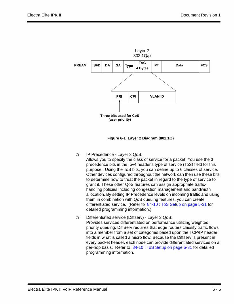
Electra Elite IPK II Document Revision 1
Electra Elite IPK II VoIP Reference Manual 6 - 5
IP Precedence - Layer 3 QoS: Allows you to specify the class of service for a packet. You use the 3 precedence bits in the Ipv4 header's type of service (ToS) field for this purpose. Using the ToS bits, you can define up to 6 classes of service. Other devices configured throughout the network can then use these bits to determine how to treat the packet in regard to the type of service to grant it. These other QoS features can assign appropriate traffic-handling policies including congestion management and bandwidth allocation. By setting IP Precedence levels on incoming traffic and using them in combination with QoS queuing features, you can create differentiated service. (Refer to 84-10 : ToS Setup on page 5-31 for detailed programming information.)
Differentiated service (Diffserv) - Layer 3 QoS: Provides services differentiated on performance utilizing weighted priority queuing. DiffServ requires that edge routers classify traffic flows into a member from a set of categories based upon the TCP/IP header fields in what is called a micro flow. Because the Diffserv is present in every packet header, each node can provide differentiated services on a per-hop basis. Refer to 84-10 : ToS Setup on page 5-31 for detailed programming information.
Figure 6-1 Layer 2 Diagram (802.1Q)
PREAM SFD DA SA TypeTAG
PT Data FCS4 Bytes
PRI CFI VLAN ID
Layer 2802.1Q/p
Three bits used for CoS(user priority)
Document Revision 1 Electra Elite IPK II
6 - 6 Network Design Considerations
SECTION 3 INTERNET BASED CONNECTIONS (XDSL, CABLE, ETC.)
Internet-based connections are becoming increasingly popular. This is mainly due to the speed and cost of xDSL and cable modem connections. For data applications, these types of connection are generally acceptable. For Voice over IP applications there are several issues that should be taken into consideration.
Asymmetric Data Rates On many internet based connections, there are different data rates for upstream and downstream. For example 1Mbps down and 256Kbps up. This works well for internet access, as generally you download files from the internet to your PC and transmit less information in the other direction. For VoIP, speech uses the same amount of bandwidth in both directions, which means that the amount of simultaneous calls can not exceed the amount of “upstream” bandwidth available.
Contention Most internet based connections specify a “contention ratio”. This is typically 50:1 for home users or 20:1 for business users. This specifies the number of users subscribed to a single connection to the Internet Service Provider (ISP). This indicates how many users share the bandwidth with other users on the internet, which means that the speeds that you are quoted are not necessarily accurate - you will receive less than these figures.
Note that it is unlikely that all of the subscribers will be using a connection at any one time, so these figures are not quite as bad as they first seem.
Network Address Translation (NAT)Usually, the equipment that your ISP provides (cable modem, ADSL router, etc.) will use Network Address Translation. This allows several devices to share one public IP address. The issues relating to the use of NAT are outlined in “Firewalls and NAT” below.
VPN Due to the use of NAT, and non-routable IP addressing, it is necessary to implement a VPN solution. This is outlined in “VPN Tunneling” below. (Refer to 4.3 Virtual Private Network (VPN) Tunnelling on page 6-9.)
QoS As discussed earlier, it is essential to have some form of Quality of Service implemented. With internet based connections, we are not in control of the many routers, switches and other network hardware that reside between our two VoIP endpoints. This means that we are unable to specify any QoS parameters on these devices.
Electra Elite IPK II Document Revision 1
Electra Elite IPK II VoIP Reference Manual 6 - 7
The only point in where the QoS can be controlled is at the VPN or firewall. This allows VoIP traffic to be prioritized over any other data that is sent out to the internet. This helps to maintain reasonable quality speech - but once the data has exited the local router/cable modem it is at the mercy of the internet.
When implementing Electra Elite IPK II IP over internet based connections it is very important that these factors are considered, and that the customer is made aware that neither the installer nor NEC will be held responsible for any quality issues experienced.
SECTION 4 FIREWALLS AND NAT
The ways in which networks have been designed to be secure (firewall, VPN services, proxy servers, etc.) and integration of NAT create problems for VoIP. This is due in part, to the endless number of different scenarios for non-real time protocols and the limited solutions for them.
4.1 Understanding the Infrastructure
The networks that are in place today look very different than the networks of yesterday. In the past, only computers and servers were connected to the network. The network was built to be as a best effort delivery mechanism, where delay and lost of information between devices was something we dealt with. Today, there is an over saturation of devices needing to gain access to the IP network. Desktop computers, fax machines, wireless PDAs, Servers, home appliances, video servers and now VoIP terminals all are fighting for bandwidth, precedence, and addresses on this converged network.
It is necessary to create some kind of Intranet environment (across the Internet), with fixed network characteristics, where VoIP solutions can tolerate some minor variations. IT personnel have been tasked with implementing different mechanisms within the network in order to support the new demands required on the converged network. Some solutions that have been implemented are:
QoS devices, in order to support precedence settings of voice packets.
Elimination of hubs in place of switches in order to support 100Mbps full-duplex transmission.
Firewall integration, to protect the internal network from external attack.
Network Address Translation (NAT) devices have been widely deployed to support the addressing issues.
Virtual Private Network (VPN) Servers have been added to Enterprise networks in order to support the security and connectivity issues for remote users.
Document Revision 1 Electra Elite IPK II
6 - 8 Network Design Considerations
Some solutions, such as the hub replacement and integration of QoS, are done behind the scenes and should have no effect on the voice application. Other solutions such as NAT and Firewall cause major disturbance to VoIP. Implementing a VPN is the only way to resolve these issues.
4.2 Firewall Integration
Network security is always a concern when connecting the Local Area Network (LAN) to the Wide Area Network (WAN). There are many ways to integrate security within the network - the most popular of which at Firewalls and Proxy servers.
FirewallsFirewalls can be implemented in both hardware and software, or a combination of both. Firewalls are frequently used to prevent unauthorized Internet users from accessing private networks connected to the Internet, especially intranets. All messages entering or leaving the intranet pass through the firewall, which examines each message and blocks those that do not meet the specified security criteria.
Proxy ServerProxy server intercepts all messages entering and leaving the network. The proxy server effectively hides the true network address.
What should be noted is that no matter which security measure is implemented, the VoIP will have to have TCP/UDP ports open within the security wall (e.g., firewall/proxy) in order for the media and control streams to flow. If any of the points within the network prevent the ports from flowing from end-to-end, the VoIP application will not work.
The ports that need to be “open” on the firewall/proxy vary depending on the particular application being used. A list of these ports is shown below, however it should be noted that the preferred solution would be to allow all ports on the Electra Elite IPK II device to be open, or to place the Electra Elite IPK II outside of the firewall.
Table 6-1 CPUII Port Assignments
Application Rx PortIPK II
Programming Block
SNMP Agent Listening Port 161 10-43-02
SNMP Destination Port 162 10-43-03
PC Programming‘ 7
DHCP Server 67 Fixed
SIP Station Listening Port 5070 84-20-01
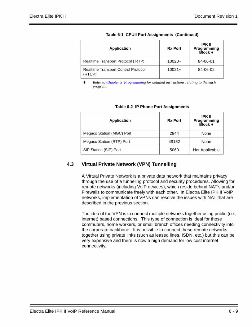
Electra Elite IPK II Document Revision 1
Electra Elite IPK II VoIP Reference Manual 6 - 9
4.3 Virtual Private Network (VPN) Tunnelling
A Virtual Private Network is a private data network that maintains privacy through the use of a tunneling protocol and security procedures. Allowing for remote networks (including VoIP devices), which reside behind NAT's and/or Firewalls to communicate freely with each other. In Electra Elite IPK II VoIP networks, implementation of VPNs can resolve the issues with NAT that are described in the previous section.
The idea of the VPN is to connect multiple networks together using public (i.e., internet) based connections. This type of connection is ideal for those commuters, home workers, or small branch offices needing connectivity into the corporate backbone. It is possible to connect these remote networks together using private links (such as leased lines, ISDN, etc.) but this can be very expensive and there is now a high demand for low cost internet connectivity.
Realtime Transport Protocol ( RTP) 10020~ 84-06-01
Realtime Transport Control Protocol (RTCP)
10021~ 84-06-02
Refer to Chapter 5 Programming for detailed instructions relating to the each program.
Table 6-2 IP Phone Port Assignments
Application Rx PortIPK II
Programming Block
Megaco Station (MGC) Port 2944 None
Megaco Station (RTP) Port 49152 None
SIP Station (SIP) Port 5060 Not Applicable
Table 6-1 CPUII Port Assignments (Continued)
Application Rx PortIPK II
Programming Block
Document Revision 1 Electra Elite IPK II
6 - 10 Network Design Considerations
Companies today are exploring the use of VPN for a variety of connectivity solutions, such as:
Remote User to Corporate Site VPNAllows employees to use their local ISP's fastest connection such as cable modems, DSL, and ISDN. For traveling users, all they would need to do is dial into their ISP's local phone number.
Site-to-site VPNAllows companies to make use of the Internet for the branch-to-branch connections, cutting the cost of the expensive point to point leased line service.
ExtranetExtranet describes one application using VPN technology. The concept would allow a company and a vendor/supplier to access network resources at each site. For example, a customer may have access to a suppliers intranet for access to product information.
VPNs can be implemented in hardware or software. For single users, such as traveling sales personnel may have a software based VPN client on their laptop computer. This would connect back to the Head Office VPN server. For larger sites, the VPN would typically be implemented using a hardware VPN - this is often incorporated in to a firewall solution.
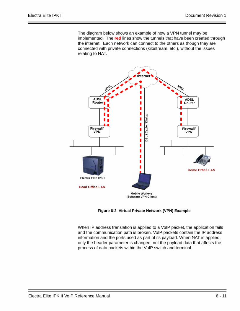
Electra Elite IPK II Document Revision 1
Electra Elite IPK II VoIP Reference Manual 6 - 11
The diagram below shows an example of how a VPN tunnel may be implemented. The red lines show the tunnels that have been created through the internet. Each network can connect to the others as though they are connected with private connections (kilostream, etc.), without the issues relating to NAT.
When IP address translation is applied to a VoIP packet, the application fails and the communication path is broken. VoIP packets contain the IP address information and the ports used as part of its payload. When NAT is applied, only the header parameter is changed, not the payload data that affects the process of data packets within the VoIP switch and terminal.
Figure 6-2 Virtual Private Network (VPN) Example
Internet
ADSLRouter
Firewall/VPN
ADSLRouter
Firewall/VPN
ADSL ADSL
DSL
/ C
able
/ D
ialu
p
Electra Elite IPK II
Head Office LAN
Home Office LAN
Mobile Workers(Software VPN Client)
Document Revision 1 Electra Elite IPK II
6 - 12 Network Design Considerations
The two most common scenarios for remote IP deployment are:
Implementation of an IP Phone with a public IP address talking with an Electra Elite IPK II behind NAT. An example would be a telecommuter.
Implementation of an IP Phone behind a NAT, which connects to the internet, terminating into an Electra Elite IPK II behind a different NAT.
When selecting VPN equipment it is important to consider Quality of Service. Generally, VPN hardware is connected to internet connections which are unreliable and out of the control of the customer. However, it is possible to set prioritization on some VPN units for voice traffic. This does not solve the unreliability of the internet, but helps to ensure that the data traffic to and from the LAN do not impair the quality of the voice traffic. (Refer to Section 2 QoS on page 6-1). NEC strongly recommends that any VPN hardware used for VoIP has the facility to prioritize voice traffic.
SECTION 5 CODEC AND BANDWIDTH
This section describes CODEC and bandwidth and their application with the Electra Elite IPK II system.
5.1 CODECs
The term CODEC (COder/DECoder) describes the technology of encoding and decoding a signal. Within VoIP this specifically refers to the algorithm used to convert analog speech to digital data for transmission on an IP network.
The Electra Elite IPK II system supports three different CODECs:
G.711 This is the ITU-T recommendation for coding of speech at 64kbps using PCM (pulse code modulation). This CODEC is often described as uncompressed as it uses the same sampling rate as the traditional telephony (TDM). G.711 has a MOS1 score of 4.2 but uses a large amount of bandwidth for transmission. This CODEC is not commonly used due to the amount of bandwidth required, although it can be acceptable in LAN environment (i.e., IP Phones connected over a 100Mbps LAN).
1. The Mean Opinion Score (MOS) provides a numerical measure of the quality of human speech at the destination end of thecircuit. The scheme uses subjective tests (opinionated scores) that are mathematically averaged to obtain a quantitative indicatorof the system performance.
Electra Elite IPK II Document Revision 1
Electra Elite IPK II VoIP Reference Manual 6 - 13
G.729A This ITU-T recommendation describes the algorithm for coding of speech signals at 8kbps using CS-ACELP (conjugate-structure algebraic code-excited linear prediction). This codec samples the analog signal at 8000Hz and uses a frame size of 10ms. This CODEC has a MOS score of 4.0.
G.729 is the most commonly used CODEC for Electra Elite IPK II VoIP installations. This is due to the fact that it offers high compression (and therefore low bandwidth) while maintaining good speech quality.
G.723 This ITU-T recommendation describes a very low bit-rate compression algorithm. The standard describes two versions 5.3Kbps and 6.4Kbps. Electra Elite IPK II uses the higher bit rate. This CODEC offers low bandwidth speech transmission, but has a lower MOS score of 3.9. This CODEC is not commonly used on the Electra Elite IPK II, but is particularly suited to low bandwidth WAN connections.
Packet Size:
Each CODEC has a set frame length. This is the period in time that the frame encapsulates. For G.729 and G.711 the frame length is 10ms and for G.723 the frame length is 30ms. It is possible to configure the packet size within the Electra Elite IPK II programming. To do this, we tell the Electra Elite IPK II how many frames to encapsulate into each packet for transmission.
For example, the G.729 has a frame length of 10ms - the packet size is set to 3 (in PRG 84-11-01). This would then give use a 10ms x 3 = 30ms packet.
5.2 Bandwidth
The amount of bandwidth required for VoIP calls depends on several factors, including:
Number of simultaneous calls
CODEC used
Frame Size
Data Networking Protocol used
IPK II CCIS Network parameters
Document Revision 1 Electra Elite IPK II
6 - 14 Network Design Considerations
The more frames encapsulated into each packet, the less bandwidth is required. This is because each packet transmitted has the same header size. Therefore, if numerous very small packets are sent then bandwidth is also being used for a large amount of header information. If we add several frames to the packet, we have less packets transmitted and therefore have less header information sent.
If we add many voice frames to each packet, less bandwidth is being used. However, this does have disadvantages. If there is a large packet size, and a particular voice packet is lost, this will have a greater impact on the speech quality. If a small quantity of voice frames per packet is being used, the effect of losing a packet is reduced.
As a general rule: The more frames per packet, the less bandwidth is used, but the quality is also lower.
Examples:
Example 1: CODEC: G.729 Frame Size: 10ms Voice Frames per Packet: 2 Voice Sample Size: 20ms (frame size x Voice Frames) Bandwidth Required: 24Kbps
Example 2: CODEC: G.729 Frame Size: 80ms Voice Frames per Packet: 8 Voice Sample Size: 80ms (frame size x Voice Frames) Bandwidth Required: 12Kbps
SECTION 6 DSP RESOURCE CALCULATION
Voice over IP (Megaco stations, SIP stations, SIP trunks) requires DSP resources to be able to convert from TDM1 to IP technologies. DSPs (Digital Signal Processors) take a TDM signal and converts to Realtime Transport Protocol (RTP) for transmission as VoIP, and vice versa. Each IP to TDM conversion requires a DSP resource.
DSP resources are provided by VoIP ETUs. For example, a MG16 VoIP ETU has 16 DSP resources. It can be difficult to work out how many DSP resources are required in an Electra Elite IPK II system, because:
not all IP Extensions/trunks will be in use at any point in time
peer-to-peer calls do not use a DSP resource
1. TDM = Time Division Multiplexing - traditional circuit based telephony
Electra Elite IPK II Document Revision 1
Electra Elite IPK II VoIP Reference Manual 6 - 15
Of course, it is possible to add up all IP devices that use a DSP resource (Megaco stations, SIP stations, SIP trunks) and provide that number of DSP resources. However, this can result in the system being over-populated with VoIP ETUs that will never be used to their capacity.
To calculate the maximum DSPs required:The manual calculations listed below are used in the Electra Elite IPK II.
Non-Peer-to-Peer Mode (PRG10-26-01=0):It is relatively simple to calculate the maximum number of DSPs for a system that is not peer-to-peer. This is a simple addition of:
VoIP extensions (VoIPE) + VoIP trunks (VoIPT)
Combine the resource figures: Combine the (extension resource figure x DSPs required for extensions) + (trunk resource figure x DSPs required for trunks) equals the total card resource required.
nTotalCardResourceRequired = (nExtCardResourceFactor x nDSPsForExt)+(nTrkCardResourceFactor x nDSPsForTrk) 1
SECTION 7 QUALITY OF SERVICE (QOS) IMPLEMENTATION
Section 2.2 Voice Quality Improvements on page 6-3 discusses some of the problems associated with voice quality. This section describes how QoS can be implemented on data networks to provide the “best case” for VoIP traffic.
It should be noted that not all network hardware supports QoS and each manufacturer will have their own methods of implementing QoS. The explanations below are intended to be as generic as possible. The installer/maintainer of the data network should be familiar with the QoS characteristics of their equipment and should be able to configure the equipment accordingly.
The term Quality of Service is commonly used to describe the actual implementation of prioritization on network hardware. This prioritization (at Layer 2 and Layer 3 of the OSI model) is described in Figure 6-1 Layer 2 Diagram (802.1Q) on page 6-5.
7.1 Prioritization
When data is transmitted through a network it typically encounters “bottlenecks”. This is where the amount of available bandwidth is reduced, or the amount of data increases. This means that the packet delivery is affected.
1. This figure will only be different to the number of required DSPs if the codecs used are the faster ones. All other codecs are amultiplication factor of 1 thus not effecting the calculation.
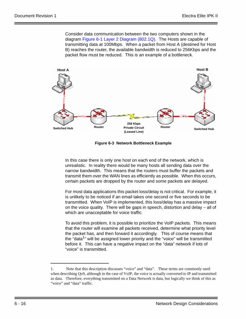
Document Revision 1 Electra Elite IPK II
6 - 16 Network Design Considerations
Consider data communication between the two computers shown in the diagram Figure 6-1 Layer 2 Diagram (802.1Q). The Hosts are capable of transmitting data at 100Mbps. When a packet from Host A (destined for Host B) reaches the router, the available bandwidth is reduced to 256Kbps and the packet flow must be reduced. This is an example of a bottleneck.
In this case there is only one host on each end of the network, which is unrealistic. In reality there would be many hosts all sending data over the narrow bandwidth. This means that the routers must buffer the packets and transmit them over the WAN lines as efficiently as possible. When this occurs, certain packets are dropped by the router and some packets are delayed.
For most data applications this packet loss/delay is not critical. For example, it is unlikely to be noticed if an email takes one second or five seconds to be transmitted. When VoIP is implemented, this loss/delay has a massive impact on the voice quality. There will be gaps in speech, distortion and delay – all of which are unacceptable for voice traffic.
To avoid this problem, it is possible to prioritize the VoIP packets. This means that the router will examine all packets received, determine what priority level the packet has, and then forward it accordingly. This of course means that the “data1” will be assigned lower priority and the “voice” will be transmitted before it. This can have a negative impact on the “data” network if lots of “voice” is transmitted.
Figure 6-3 Network Bottleneck Example
1. Note that this description discusses “voice” and “data”. These terms are commonly used when describing QoS, although in the case of VoIP, the voice is actually converted to IP and transmitted as data. Therefore, everything transmitted on a Data Network is data, but logically we think of this as “voice” and “data” traffic.
Host A Host B
Switched Hub Router256 Kbps
Private Circuit(Leased Line)
Router Switched Hub
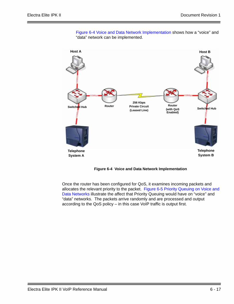
Electra Elite IPK II Document Revision 1
Electra Elite IPK II VoIP Reference Manual 6 - 17
Figure 6-4 Voice and Data Network Implementation shows how a “voice” and “data” network can be implemented.
Once the router has been configured for QoS, it examines incoming packets and allocates the relevant priority to the packet. Figure 6-5 Priority Queuing on Voice and Data Networks illustrate the affect that Priority Queuing would have on “voice” and “data” networks. The packets arrive randomly and are processed and output according to the QoS policy – in this case VoIP traffic is output first.
Figure 6-4 Voice and Data Network Implementation
Host A Host B
Switched Hub Router256 Kbps
Private Circuit(Leased Line)
Router(with QoS Enabled)
Switched Hub
TelephoneSystem A
TelephoneSystem B
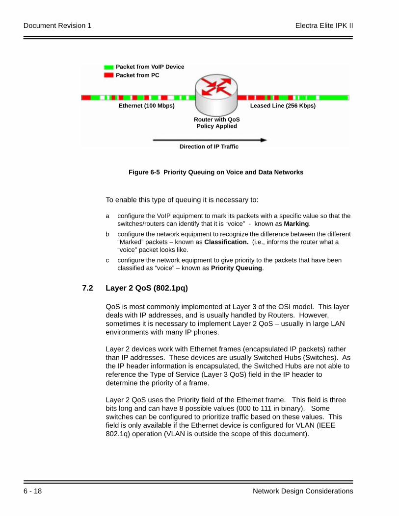
Document Revision 1 Electra Elite IPK II
6 - 18 Network Design Considerations
To enable this type of queuing it is necessary to:
a configure the VoIP equipment to mark its packets with a specific value so that the switches/routers can identify that it is “voice” - known as Marking.
b configure the network equipment to recognize the difference between the different “Marked” packets – known as Classification. (i.e., informs the router what a “voice” packet looks like.
c configure the network equipment to give priority to the packets that have been classified as “voice” – known as Priority Queuing.
7.2 Layer 2 QoS (802.1pq)
QoS is most commonly implemented at Layer 3 of the OSI model. This layer deals with IP addresses, and is usually handled by Routers. However, sometimes it is necessary to implement Layer 2 QoS – usually in large LAN environments with many IP phones.
Layer 2 devices work with Ethernet frames (encapsulated IP packets) rather than IP addresses. These devices are usually Switched Hubs (Switches). As the IP header information is encapsulated, the Switched Hubs are not able to reference the Type of Service (Layer 3 QoS) field in the IP header to determine the priority of a frame.
Layer 2 QoS uses the Priority field of the Ethernet frame. This field is three bits long and can have 8 possible values (000 to 111 in binary). Some switches can be configured to prioritize traffic based on these values. This field is only available if the Ethernet device is configured for VLAN (IEEE 802.1q) operation (VLAN is outside the scope of this document).
Figure 6-5 Priority Queuing on Voice and Data Networks
Packet from VoIP DevicePacket from PC
Ethernet (100 Mbps) Leased Line (256 Kbps)
Direction of IP Traffic
Router with QoSPolicy Applied
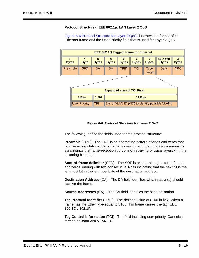
Electra Elite IPK II Document Revision 1
Electra Elite IPK II VoIP Reference Manual 6 - 19
Protocol Structure - IEEE 802.1p: LAN Layer 2 QoS
Figure 6-6 Protocol Structure for Layer 2 QoS illustrates the format of an Ethernet frame and the User Priority field that is used for Layer 2 QoS.
The following define the fields used for the protocol structure:
Preamble (PRE) - The PRE is an alternating pattern of ones and zeros that tells receiving stations that a frame is coming, and that provides a means to synchronize the frame-reception portions of receiving physical layers with the incoming bit stream.
Start-of-frame delimiter (SFD) - The SOF is an alternating pattern of ones and zeros, ending with two consecutive 1-bits indicating that the next bit is the left-most bit in the left-most byte of the destination address.
Destination Address (DA) - The DA field identifies which station(s) should receive the frame.
Source Addresses (SA) - The SA field identifies the sending station.
Tag Protocol Identifier (TPID) - The defined value of 8100 in hex. When a frame has the EtherType equal to 8100, this frame carries the tag IEEE 802.1Q / 802.1P.
Tag Control Information (TCI) - The field including user priority, Canonical format indicator and VLAN ID.
Figure 6-6 Protocol Structure for Layer 2 QoS
IEEE 802.1Q Tagged Frame for Ethernet
7 Bytes
1Byte
6Bytes
6Bytes
2Bytes
2Bytes
2Bytes
42~1496Bytes
4Bytes
Preamble SFD DA SA TPID TCI Type Length
Data CRC
Expanded view of TCI Field
3 Bits 1 Bit 12 Bits
User Priority CFI Bits of VLAN ID (VID) to identify possible VLANs
IEEE 802.1Q Tagged Frame for Ethernet
7 Bytes
1Byte
6Bytes
6Bytes
2Bytes
2Bytes
2Bytes
42~1496Bytes
4Bytes
Preamble SFD DA SA TPID TCI Type Length
Data CRC
Expanded view of TCI Field
3 Bits 1 Bit 12 Bits
User Priority CFI Bits of VLAN ID (VID) to identify possible VLANs
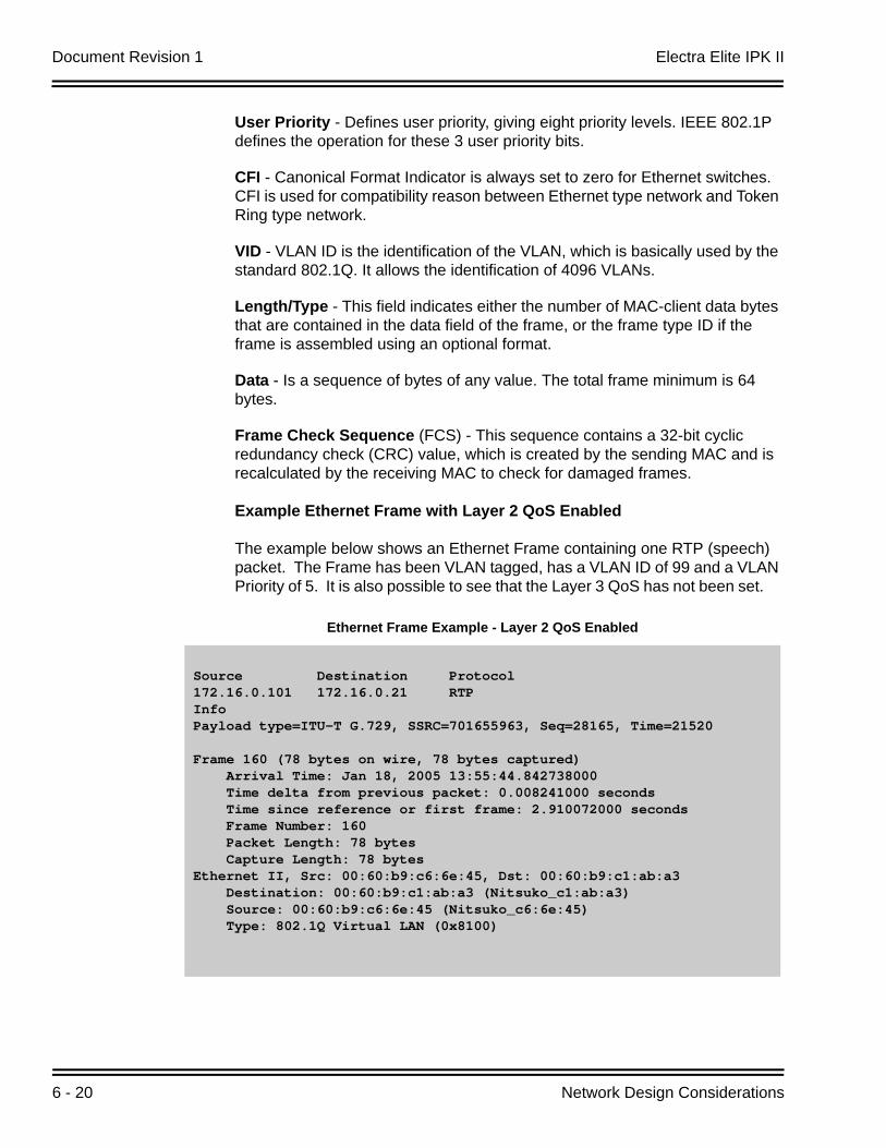
Document Revision 1 Electra Elite IPK II
6 - 20 Network Design Considerations
User Priority - Defines user priority, giving eight priority levels. IEEE 802.1P defines the operation for these 3 user priority bits.
CFI - Canonical Format Indicator is always set to zero for Ethernet switches. CFI is used for compatibility reason between Ethernet type network and Token Ring type network.
VID - VLAN ID is the identification of the VLAN, which is basically used by the standard 802.1Q. It allows the identification of 4096 VLANs.
Length/Type - This field indicates either the number of MAC-client data bytes that are contained in the data field of the frame, or the frame type ID if the frame is assembled using an optional format.
Data - Is a sequence of bytes of any value. The total frame minimum is 64 bytes.
Frame Check Sequence (FCS) - This sequence contains a 32-bit cyclic redundancy check (CRC) value, which is created by the sending MAC and is recalculated by the receiving MAC to check for damaged frames.
Example Ethernet Frame with Layer 2 QoS Enabled
The example below shows an Ethernet Frame containing one RTP (speech) packet. The Frame has been VLAN tagged, has a VLAN ID of 99 and a VLAN Priority of 5. It is also possible to see that the Layer 3 QoS has not been set.
Ethernet Frame Example - Layer 2 QoS Enabled
Source Destination Protocol172.16.0.101 172.16.0.21 RTP InfoPayload type=ITU-T G.729, SSRC=701655963, Seq=28165, Time=21520
Frame 160 (78 bytes on wire, 78 bytes captured) Arrival Time: Jan 18, 2005 13:55:44.842738000 Time delta from previous packet: 0.008241000 seconds Time since reference or first frame: 2.910072000 seconds Frame Number: 160 Packet Length: 78 bytes Capture Length: 78 bytesEthernet II, Src: 00:60:b9:c6:6e:45, Dst: 00:60:b9:c1:ab:a3 Destination: 00:60:b9:c1:ab:a3 (Nitsuko_c1:ab:a3) Source: 00:60:b9:c6:6e:45 (Nitsuko_c6:6e:45) Type: 802.1Q Virtual LAN (0x8100)
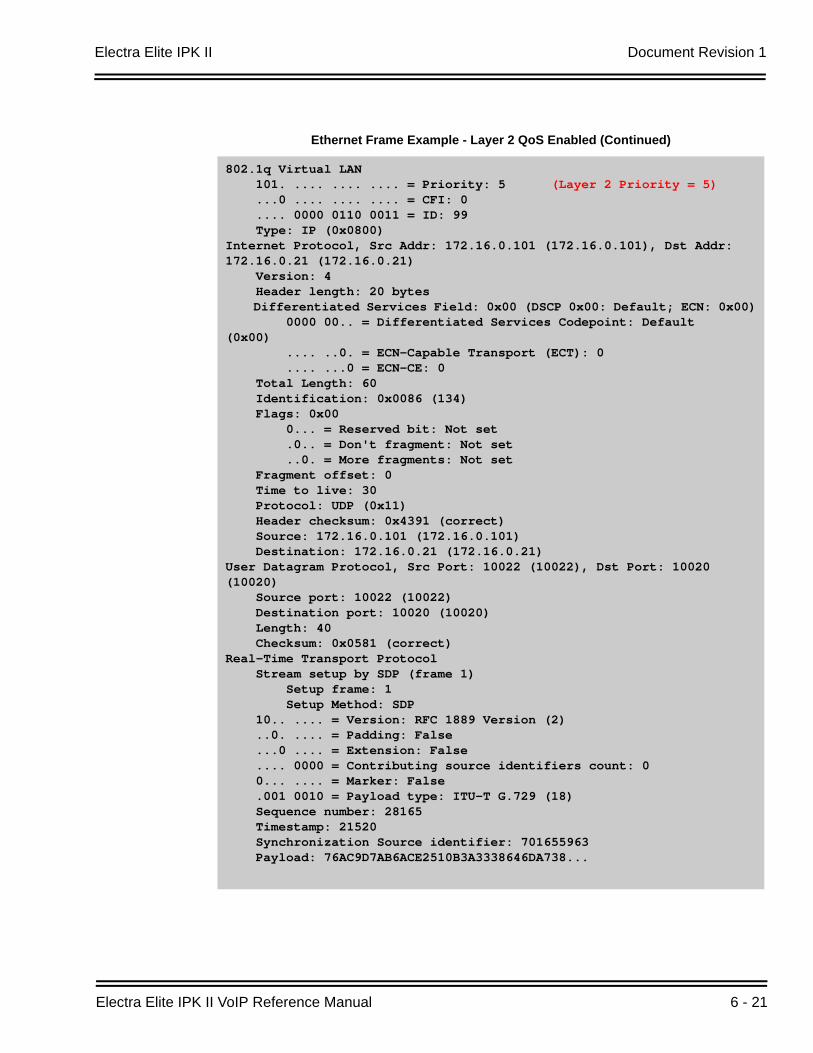
Electra Elite IPK II Document Revision 1
Electra Elite IPK II VoIP Reference Manual 6 - 21
Ethernet Frame Example - Layer 2 QoS Enabled (Continued)
802.1q Virtual LAN 101. .... .... .... = Priority: 5 (Layer 2 Priority = 5) ...0 .... .... .... = CFI: 0 .... 0000 0110 0011 = ID: 99 Type: IP (0x0800)Internet Protocol, Src Addr: 172.16.0.101 (172.16.0.101), Dst Addr: 172.16.0.21 (172.16.0.21) Version: 4 Header length: 20 bytes Differentiated Services Field: 0x00 (DSCP 0x00: Default; ECN: 0x00) 0000 00.. = Differentiated Services Codepoint: Default (0x00) .... ..0. = ECN-Capable Transport (ECT): 0 .... ...0 = ECN-CE: 0 Total Length: 60 Identification: 0x0086 (134) Flags: 0x00 0... = Reserved bit: Not set .0.. = Don't fragment: Not set ..0. = More fragments: Not set Fragment offset: 0 Time to live: 30 Protocol: UDP (0x11) Header checksum: 0x4391 (correct) Source: 172.16.0.101 (172.16.0.101) Destination: 172.16.0.21 (172.16.0.21)User Datagram Protocol, Src Port: 10022 (10022), Dst Port: 10020 (10020) Source port: 10022 (10022) Destination port: 10020 (10020) Length: 40 Checksum: 0x0581 (correct)Real-Time Transport Protocol Stream setup by SDP (frame 1) Setup frame: 1 Setup Method: SDP 10.. .... = Version: RFC 1889 Version (2) ..0. .... = Padding: False ...0 .... = Extension: False .... 0000 = Contributing source identifiers count: 0 0... .... = Marker: False .001 0010 = Payload type: ITU-T G.729 (18) Sequence number: 28165 Timestamp: 21520 Synchronization Source identifier: 701655963 Payload: 76AC9D7AB6ACE2510B3A3338646DA738...
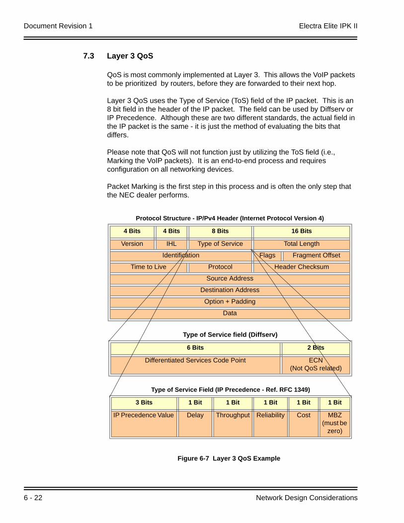
Document Revision 1 Electra Elite IPK II
6 - 22 Network Design Considerations
7.3 Layer 3 QoS
QoS is most commonly implemented at Layer 3. This allows the VoIP packets to be prioritized by routers, before they are forwarded to their next hop.
Layer 3 QoS uses the Type of Service (ToS) field of the IP packet. This is an 8 bit field in the header of the IP packet. The field can be used by Diffserv or IP Precedence. Although these are two different standards, the actual field in the IP packet is the same - it is just the method of evaluating the bits that differs.
Please note that QoS will not function just by utilizing the ToS field (i.e., Marking the VoIP packets). It is an end-to-end process and requires configuration on all networking devices.
Packet Marking is the first step in this process and is often the only step that the NEC dealer performs.
Figure 6-7 Layer 3 QoS Example
Protocol Structure - IP/Pv4 Header (Internet Protocol Version 4)
4 Bits 4 Bits 8 Bits 16 Bits
Version IHL Type of Service Total Length
Identification Flags Fragment Offset
Time to Live Protocol Header Checksum
Source Address
Destination Address
Option + Padding
Data
Type of Service field (Diffserv)
6 Bits 2 Bits
Differentiated Services Code Point ECN(Not QoS related)
Type of Service Field (IP Precedence - Ref. RFC 1349)
3 Bits 1 Bit 1 Bit 1 Bit 1 Bit 1 Bit
IP Precedence Value Delay Throughput Reliability Cost MBZ(must be
zero)
Electra Elite IPK II Document Revision 1
Electra Elite IPK II VoIP Reference Manual 6 - 23
Listed below are the fields used in Figure 6-7 Layer 3 QoS Example.
Version - the version of IP currently used.
IP Header Length (IHL) - datagram header length. Points to the beginning of the data. The minimum value for a correct header is 5.
Type-of-Service - Indicates the quality of service desired by specifying how an upper-layer protocol would like a current datagram to be handled, and assigns datagrams various levels of importance. This field is used for the assignment of Precedence, Delay, Throughput and Reliability.
Total Length - Specifies the length, in bytes, of the entire IP packet, including the data and header. The maximum length could be specified by this field is 65,535 bytes. Typically, hosts are prepared to accept datagrams up to 576 bytes.
Identification - Contains an integer that identifies the current datagram. This field is assigned by sender to help receiver to assemble the datagram fragments.
Flags - Consists of a 3-bit field of which the two low-order (least-significant) bits control fragmentation. The low-order bit specifies whether the packet can be fragmented. The middle bit specifies whether the packet is the last fragment in a series of fragmented packets. The third or high-order bit is not used.
Fragment Offset - This 13 bits field indicates the position of the fragment's data relative to the beginning of the data in the original datagram, which allows the destination IP process to properly reconstruct the original datagram.
Time-to-Live - It is a counter that gradually decrements down to zero, at which point the datagram is discarded. This keeps packets from looping endlessly.
Protocol - Indicates which upper-layer protocol receives incoming packets after IP processing is complete.
Header Checksum - Helps ensure IP header integrity. Since some header fields change, e.g., Time To Live, this is recomputed and verified at each point that the Internet header is processed.
Source Address-Specifies the sending node.
Destination Address-Specifies the receiving node.
Options - Allows IP to support various options, such as security.
Data - Contains upper-layer information.
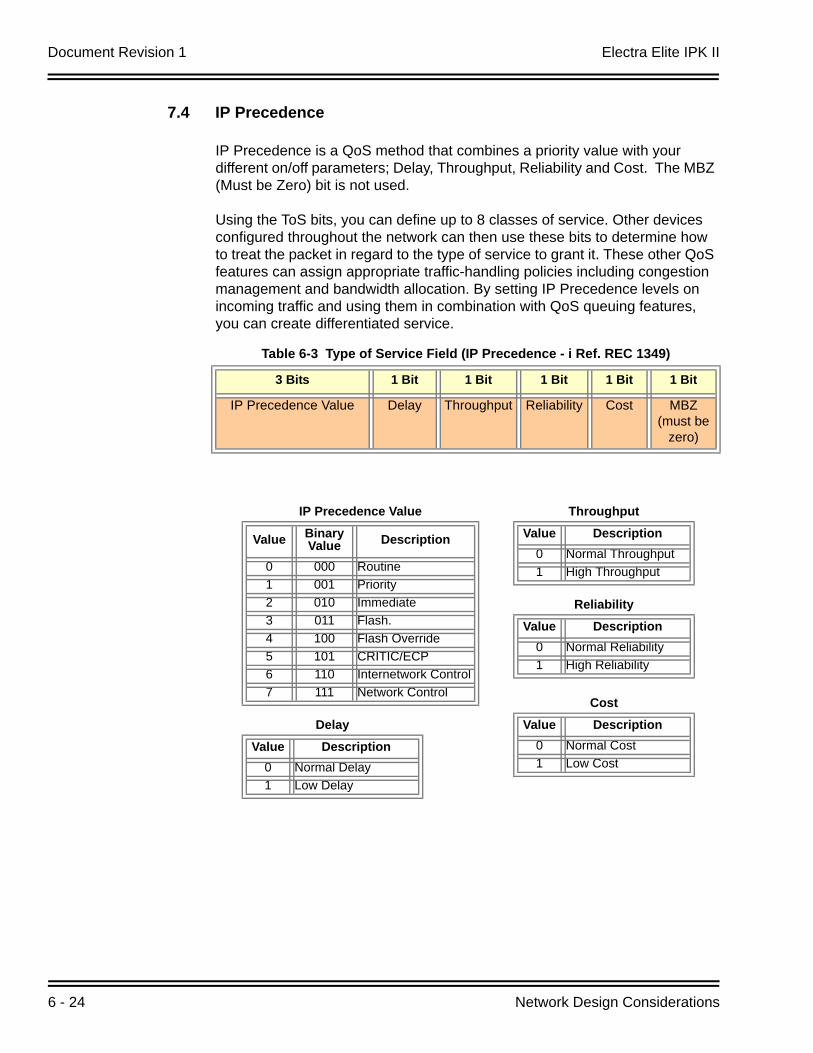
Document Revision 1 Electra Elite IPK II
6 - 24 Network Design Considerations
7.4 IP Precedence
IP Precedence is a QoS method that combines a priority value with your different on/off parameters; Delay, Throughput, Reliability and Cost. The MBZ (Must be Zero) bit is not used.
Using the ToS bits, you can define up to 8 classes of service. Other devices configured throughout the network can then use these bits to determine how to treat the packet in regard to the type of service to grant it. These other QoS features can assign appropriate traffic-handling policies including congestion management and bandwidth allocation. By setting IP Precedence levels on incoming traffic and using them in combination with QoS queuing features, you can create differentiated service.
Table 6-3 Type of Service Field (IP Precedence - i Ref. REC 1349)
3 Bits 1 Bit 1 Bit 1 Bit 1 Bit 1 Bit
IP Precedence Value Delay Throughput Reliability Cost MBZ(must be
zero)
IP Precedence Value
Value Binary Value Description
0 000 Routine1 001 Priority2 010 Immediate3 011 Flash.4 100 Flash Override5 101 CRITIC/ECP6 110 Internetwork Control7 111 Network Control
Delay
Value Description0 Normal Delay1 Low Delay
Throughput
Value Description0 Normal Throughput1 High Throughput
Reliability
Value Description0 Normal Reliability1 High Reliability
Cost
Value Description0 Normal Cost1 Low Cost
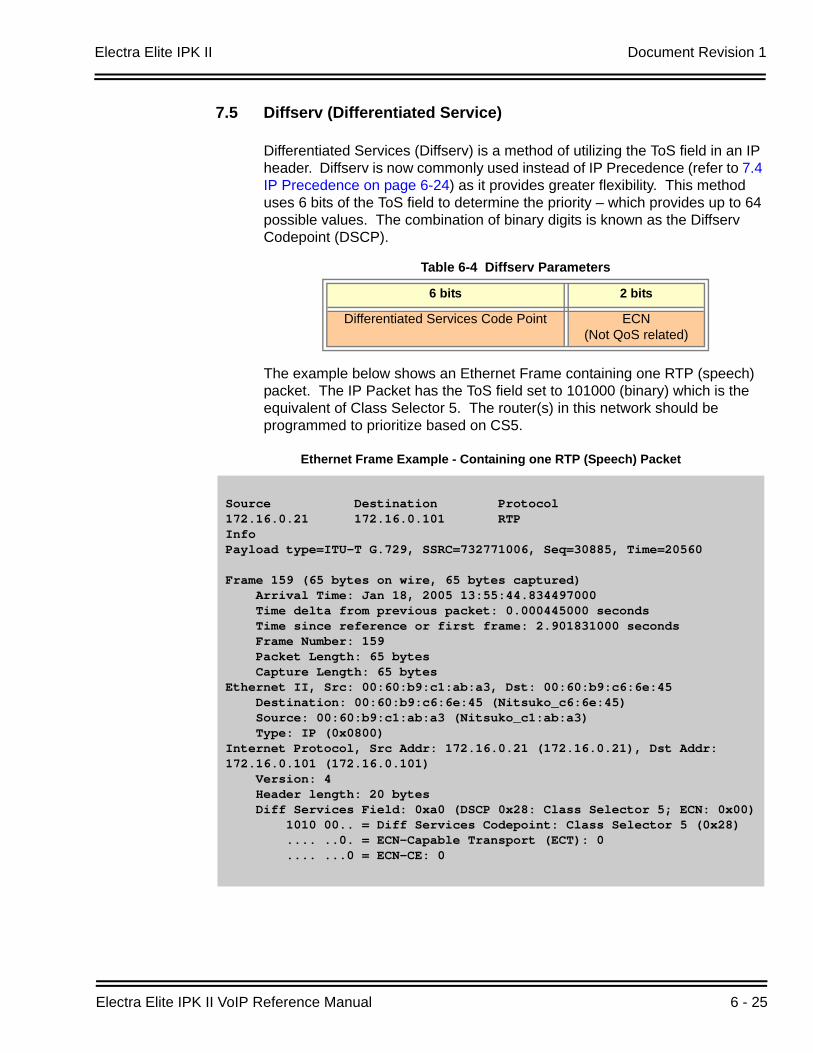
Electra Elite IPK II Document Revision 1
Electra Elite IPK II VoIP Reference Manual 6 - 25
7.5 Diffserv (Differentiated Service)
Differentiated Services (Diffserv) is a method of utilizing the ToS field in an IP header. Diffserv is now commonly used instead of IP Precedence (refer to 7.4 IP Precedence on page 6-24) as it provides greater flexibility. This method uses 6 bits of the ToS field to determine the priority – which provides up to 64 possible values. The combination of binary digits is known as the Diffserv Codepoint (DSCP).
The example below shows an Ethernet Frame containing one RTP (speech) packet. The IP Packet has the ToS field set to 101000 (binary) which is the equivalent of Class Selector 5. The router(s) in this network should be programmed to prioritize based on CS5.
Table 6-4 Diffserv Parameters
6 bits 2 bits
Differentiated Services Code Point ECN(Not QoS related)
Ethernet Frame Example - Containing one RTP (Speech) Packet
Source Destination Protocol172.16.0.21 172.16.0.101 RTP InfoPayload type=ITU-T G.729, SSRC=732771006, Seq=30885, Time=20560
Frame 159 (65 bytes on wire, 65 bytes captured) Arrival Time: Jan 18, 2005 13:55:44.834497000 Time delta from previous packet: 0.000445000 seconds Time since reference or first frame: 2.901831000 seconds Frame Number: 159 Packet Length: 65 bytes Capture Length: 65 bytesEthernet II, Src: 00:60:b9:c1:ab:a3, Dst: 00:60:b9:c6:6e:45 Destination: 00:60:b9:c6:6e:45 (Nitsuko_c6:6e:45) Source: 00:60:b9:c1:ab:a3 (Nitsuko_c1:ab:a3) Type: IP (0x0800)Internet Protocol, Src Addr: 172.16.0.21 (172.16.0.21), Dst Addr: 172.16.0.101 (172.16.0.101) Version: 4 Header length: 20 bytes Diff Services Field: 0xa0 (DSCP 0x28: Class Selector 5; ECN: 0x00) 1010 00.. = Diff Services Codepoint: Class Selector 5 (0x28) .... ..0. = ECN-Capable Transport (ECT): 0 .... ...0 = ECN-CE: 0
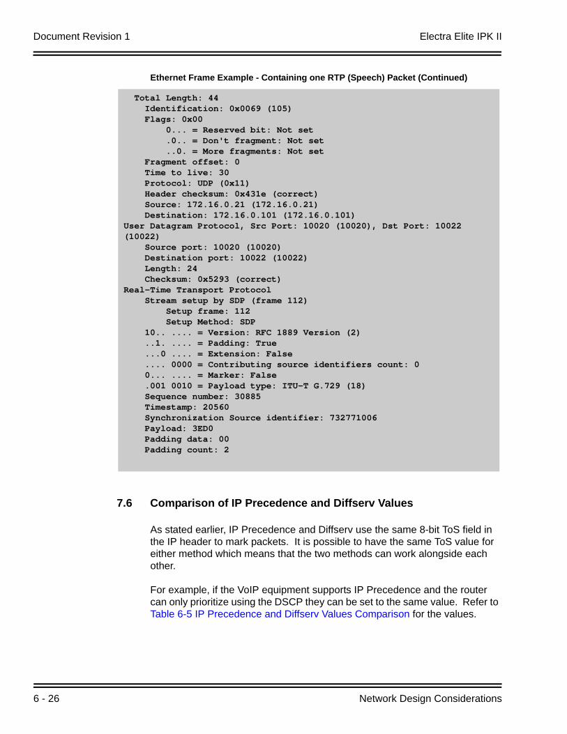
Document Revision 1 Electra Elite IPK II
6 - 26 Network Design Considerations
7.6 Comparison of IP Precedence and Diffserv Values
As stated earlier, IP Precedence and Diffserv use the same 8-bit ToS field in the IP header to mark packets. It is possible to have the same ToS value for either method which means that the two methods can work alongside each other.
For example, if the VoIP equipment supports IP Precedence and the router can only prioritize using the DSCP they can be set to the same value. Refer to Table 6-5 IP Precedence and Diffserv Values Comparison for the values.
Ethernet Frame Example - Containing one RTP (Speech) Packet (Continued)
Total Length: 44 Identification: 0x0069 (105) Flags: 0x00 0... = Reserved bit: Not set .0.. = Don't fragment: Not set ..0. = More fragments: Not set Fragment offset: 0 Time to live: 30 Protocol: UDP (0x11) Header checksum: 0x431e (correct) Source: 172.16.0.21 (172.16.0.21) Destination: 172.16.0.101 (172.16.0.101)User Datagram Protocol, Src Port: 10020 (10020), Dst Port: 10022 (10022) Source port: 10020 (10020) Destination port: 10022 (10022) Length: 24 Checksum: 0x5293 (correct)Real-Time Transport Protocol Stream setup by SDP (frame 112) Setup frame: 112 Setup Method: SDP 10.. .... = Version: RFC 1889 Version (2) ..1. .... = Padding: True ...0 .... = Extension: False .... 0000 = Contributing source identifiers count: 0 0... .... = Marker: False .001 0010 = Payload type: ITU-T G.729 (18) Sequence number: 30885 Timestamp: 20560 Synchronization Source identifier: 732771006 Payload: 3ED0 Padding data: 00 Padding count: 2
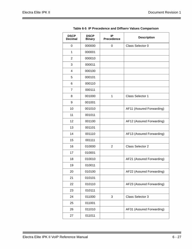
Electra Elite IPK II Document Revision 1
Electra Elite IPK II VoIP Reference Manual 6 - 27
Table 6-5 IP Precedence and Diffserv Values Comparison
DSCP Decimal
DSCP Binary
IP Precedence Description
0 000000 0 Class Selector 0
1 000001
2 000010
3 000011
4 000100
5 000101
6 000110
7 000111
8 001000 1 Class Selector 1
9 001001
10 001010 AF11 (Assured Forwarding)
11 001011
12 001100 AF12 (Assured Forwarding)
13 001101
14 001110 AF13 (Assured Forwarding)
15 001111
16 010000 2 Class Selector 2
17 010001
18 010010 AF21 (Assured Forwarding)
19 010011
20 010100 AF22 (Assured Forwarding)
21 010101
22 010110 AF23 (Assured Forwarding)
23 010111
24 011000 3 Class Selector 3
25 011001
26 011010 AF31 (Assured Forwarding)
27 011011
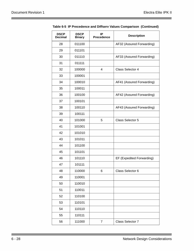
Document Revision 1 Electra Elite IPK II
6 - 28 Network Design Considerations
28 011100 AF32 (Assured Forwarding)
29 011101
30 011110 AF33 (Assured Forwarding)
31 011111
32 100000 4 Class Selector 4
33 100001
34 100010 AF41 (Assured Forwarding)
35 100011
36 100100 AF42 (Assured Forwarding)
37 100101
38 100110 AF43 (Assured Forwarding)
39 100111
40 101000 5 Class Selector 5
41 101001
42 101010
43 101011
44 101100
45 101101
46 101110 EF (Expedited Forwarding)
47 101111
48 110000 6 Class Selector 6
49 110001
50 110010
51 110011
52 110100
53 110101
54 110110
55 110111
56 111000 7 Class Selector 7
Table 6-5 IP Precedence and Diffserv Values Comparison (Continued)
DSCP Decimal
DSCP Binary
IP Precedence Description
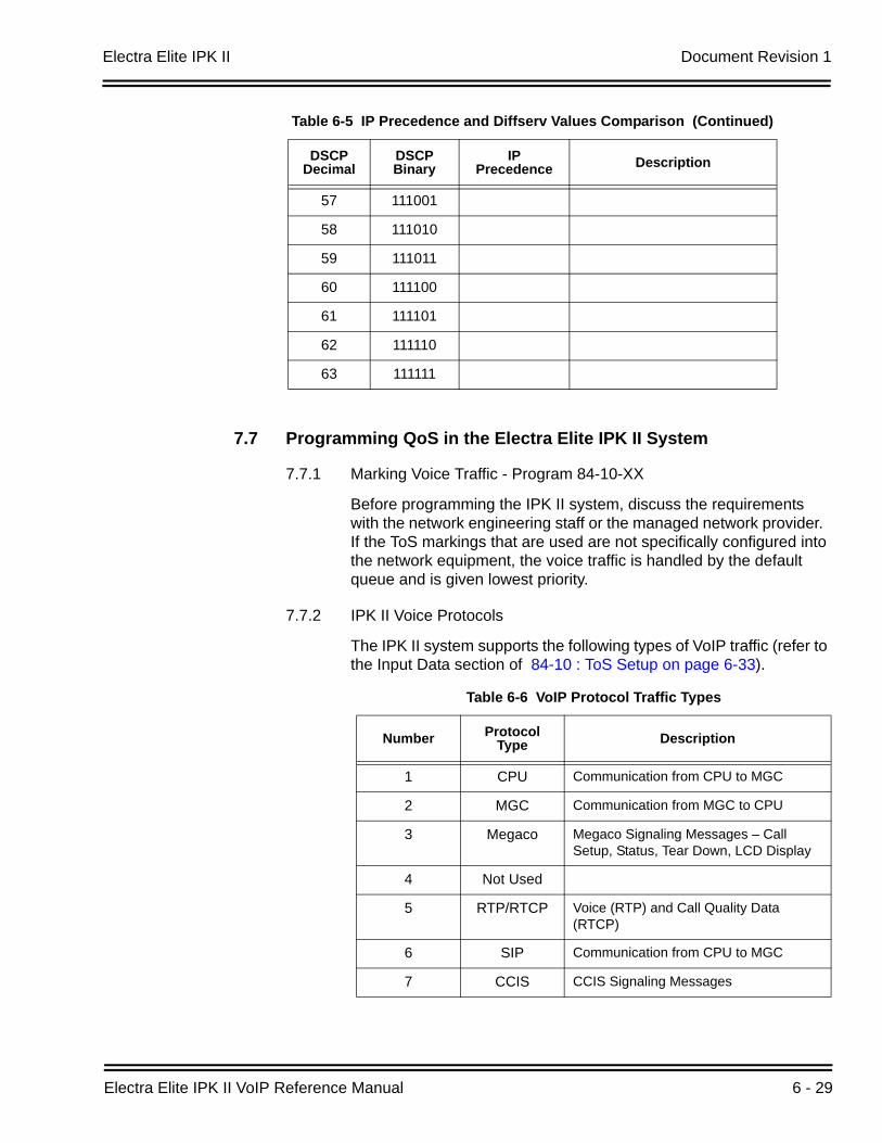
Electra Elite IPK II Document Revision 1
Electra Elite IPK II VoIP Reference Manual 6 - 29
7.7 Programming QoS in the Electra Elite IPK II System
7.7.1 Marking Voice Traffic - Program 84-10-XX
Before programming the IPK II system, discuss the requirements with the network engineering staff or the managed network provider. If the ToS markings that are used are not specifically configured into the network equipment, the voice traffic is handled by the default queue and is given lowest priority.
7.7.2 IPK II Voice Protocols
The IPK II system supports the following types of VoIP traffic (refer to the Input Data section of 84-10 : ToS Setup on page 6-33).
57 111001
58 111010
59 111011
60 111100
61 111101
62 111110
63 111111
Table 6-6 VoIP Protocol Traffic Types
Number Protocol Type Description
1 CPU Communication from CPU to MGC
2 MGC Communication from MGC to CPU
3 Megaco Megaco Signaling Messages – Call Setup, Status, Tear Down, LCD Display
4 Not Used
5 RTP/RTCP Voice (RTP) and Call Quality Data (RTCP)
6 SIP Communication from CPU to MGC
7 CCIS CCIS Signaling Messages
Table 6-5 IP Precedence and Diffserv Values Comparison (Continued)
DSCP Decimal
DSCP Binary
IP Precedence Description
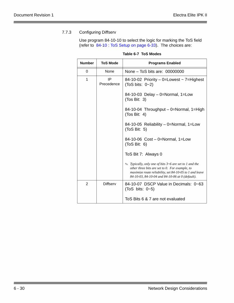
Document Revision 1 Electra Elite IPK II
6 - 30 Network Design Considerations
7.7.3 Configuring Diffserv
Use program 84-10-10 to select the logic for marking the ToS field (refer to 84-10 : ToS Setup on page 6-33). The choices are:
Table 6-7 ToS Modes
Number ToS Mode Programs Enabled
0 None None – ToS bits are: 00000000
1 IP Precedence
84-10-02 Priority – 0=Lowest ~ 7=Highest(ToS bits: 0~2)
84-10-03 Delay – 0=Normal, 1=Low(Tos Bit: 3)
84-10-04 Throughput – 0=Normal, 1=High(Tos Bit: 4)
84-10-05 Reliability – 0=Normal, 1=Low(ToS Bit: 5)
84-10-06 Cost – 0=Normal, 1=Low(ToS Bit: 6)
ToS Bit 7: Always 0
Typically, only one of bits 3~6 are set to 1 and the other three bits are set to 0. For example, to maximize route reliability, set 84-10-05 to 1 and leave 84-10-03, 84-10-04 and 84-10-06 at 0 (default).
2 Diffserv 84-10-07 DSCP Value in Decimals: 0~63(ToS bits: 0~5)
ToS Bits 6 & 7 are not evaluated
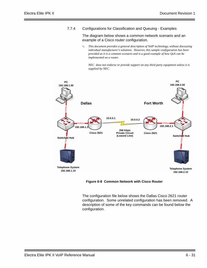
Electra Elite IPK II Document Revision 1
Electra Elite IPK II VoIP Reference Manual 6 - 31
7.7.4 Configurations for Classification and Queuing - Examples
The diagram below shows a common network scenario and an example of a Cisco router configuration.
This document provides a general description of VoIP technology, without discussing individual manufacturer’s solutions. However, this sample configuration has been provided as it is a common scenario and is a good example of how QoS can be implemented on a router.
NEC does not endorse or provide support on any third party equipment unless it is supplied by NEC.
The configuration file below shows the Dallas Cisco 2621 router configuration. Some unrelated configuration has been removed. A description of some of the key commands can be found below the configuration.
Figure 6-8 Common Network with Cisco Router
Dallas Fort Worth
PC192.168.1.50
PC192.168.2.50
Switched Hub
Telephone System192.168.1.10
Telephone System192.168.2.10
Switched HubCisco 2621
192.168.2.1192.168.1.1
Cisco 2621256 Kbps
Private Circuit(Leased Line)
10.0.0.1 10.0.0.2
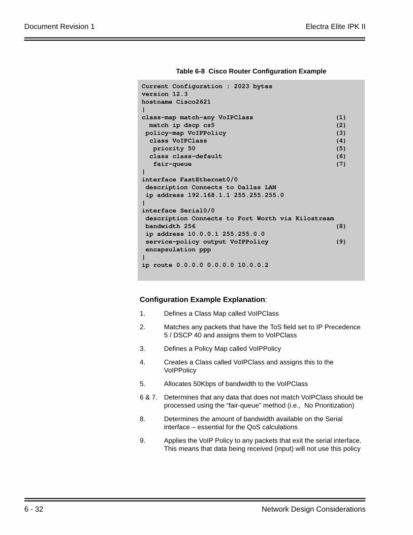
Document Revision 1 Electra Elite IPK II
6 - 32 Network Design Considerations
Configuration Example Explanation:
1. Defines a Class Map called VoIPClass
2. Matches any packets that have the ToS field set to IP Precedence 5 / DSCP 40 and assigns them to VoIPClass
3. Defines a Policy Map called VoIPPolicy
4. Creates a Class called VoIPClass and assigns this to the VoIPPolicy
5. Allocates 50Kbps of bandwidth to the VoIPClass
6 & 7. Determines that any data that does not match VoIPClass should be processed using the “fair-queue” method (i.e., No Prioritization)
8. Determines the amount of bandwidth available on the Serial interface – essential for the QoS calculations
9. Applies the VoIP Policy to any packets that exit the serial interface. This means that data being received (input) will not use this policy
Table 6-8 Cisco Router Configuration Example
Current Configuration : 2023 bytesversion 12.3hostname Cisco2621|class-map match-any VoIPClass (1) match ip dscp cs5 (2) policy-map VoIPPolicy (3) class VoIPClass (4) priority 50 (5) class class-default (6) fair-queue (7)|interface FastEthernet0/0 description Connects to Dallas LAN ip address 192.168.1.1 255.255.255.0|interface Serial0/0 description Connects to Fort Worth via Kilostream bandwidth 256 (8) ip address 10.0.0.1 255.255.0.0 service-policy output VoIPPolicy (9) encapsulation ppp|ip route 0.0.0.0 0.0.0.0 10.0.0.2
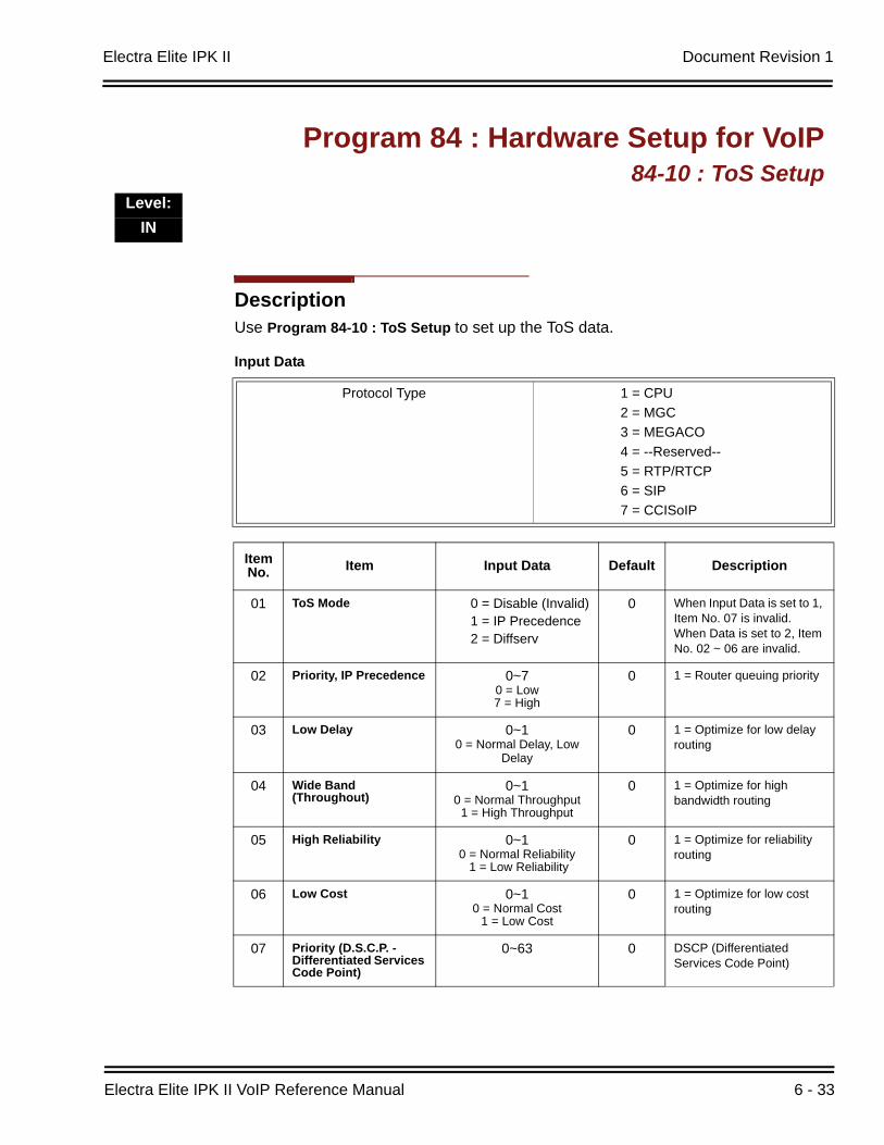
Electra Elite IPK II Document Revision 1
Electra Elite IPK II VoIP Reference Manual 6 - 33
DescriptionUse Program 84-10 : ToS Setup to set up the ToS data.
Program 84 : Hardware Setup for VoIP84-10 : ToS Setup
Level:IN
Input Data
Protocol Type 1 = CPU2 = MGC3 = MEGACO4 = --Reserved--5 = RTP/RTCP6 = SIP7 = CCISoIP
Item No. Item Input Data Default Description
01 ToS Mode 0 = Disable (Invalid)1 = IP Precedence2 = Diffserv
0 When Input Data is set to 1, Item No. 07 is invalid. When Data is set to 2, Item No. 02 ~ 06 are invalid.
02 Priority, IP Precedence 0~70 = Low7 = High
0 1 = Router queuing priority
03 Low Delay 0~10 = Normal Delay, Low
Delay
0 1 = Optimize for low delay routing
04 Wide Band (Throughout)
0~10 = Normal Throughput
1 = High Throughput
0 1 = Optimize for high bandwidth routing
05 High Reliability 0~10 = Normal Reliability
1 = Low Reliability
0 1 = Optimize for reliability routing
06 Low Cost 0~10 = Normal Cost
1 = Low Cost
0 1 = Optimize for low cost routing
07 Priority (D.S.C.P. -Differentiated Services Code Point)
0~63 0 DSCP (Differentiated Services Code Point)

Document Revision 1 Electra Elite IPK II
6 - 34 Network Design Considerations
Conditions
The system must be reset for these program options to take affect.
Feature Cross ReferenceVoice Over Internet Protocol (VoIP)
Electra Elite IPK II VoIP Reference Manual 7 - 1
Tro
ub
lesh
oo
ting
7Troubleshooting
SECTION 1 INTRODUCTION
This section provides some helpful tips for troubleshooting IP on the Electra Elite IPK II system.
The first step in resolving any issues would be to read through the relevant chapters in the manual and refer to the configuration examples. If you are unable to resolve the issue using the documentation, it may be helpful to use the tools outlined below.
SECTION 2 PING
This is one of the most useful tools available to troubleshoot IP connectivity. PING is a standard component of Microsoft Windows® and is also implemented on the IPK II IP Phones. Ping sends a small IP packet to a specified destination and waits for a response back.
It should be possible to ping IP Phones, the CPUII, VoIP ETU and any other devices on the network. Send a ping and wait for a reply. If a reply is not received, the ping response “times out”. This indicates a connection problem.
Refer to Figure 7-1 Ping Traces on page 7-2 for examples of these two conditions.
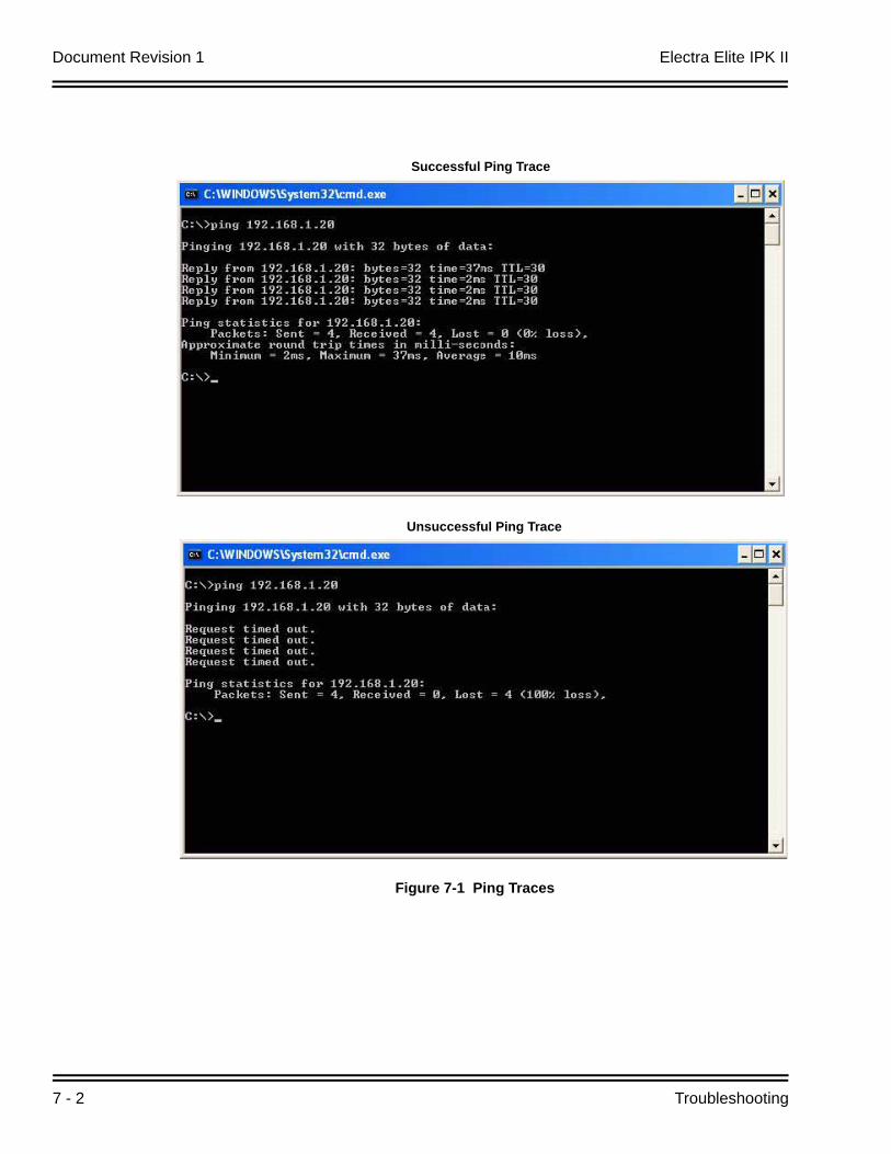
Document Revision 1 Electra Elite IPK II
7 - 2 Troubleshooting
Figure 7-1 Ping Traces
Unsuccessful Ping Trace
Successful Ping Trace
Electra Elite IPK II Document Revision 1
Electra Elite IPK II VoIP Reference Manual 7 - 3
If unable to ping a device, it may mean that either the source or destination device:
is not configured correctly
is not connected to the LAN (e.g., cable disconnected)
has a developed a fault
or any device in between the source or destination may be faulty (e.g., routers)
2.1 Pinging from a PC
The command syntax for ping is: ping [-t] [-n count] [-l size] target
-t (optional) continually sends PING requests until Ctrl-C is pressed to cancel -n (optional) sends a specified number of PING requests -l (optional) sends packets of a specified size (bytes) target the destination IP address or host name
Note that there are other options available with the Microsoft Windows® implementation of ping. The most commonly used options are listed above.
Examples:
ping 192.168.2.100 -t Continually pings 192.168.2.100 until Ctrl-c pressed ping
192.168.2.100 -n 10 -l 40 Sends ten 40-byte packets to 192.168.2.100
ping 192.168.2.100 Sends four 32-byte packets (default) to 192.168.2.100
2.2 Pinging from an Electra Elite IPK II IP Phone
The System IP Phone has a version of ping within the Maintenance Menu. Enter Program Mode (Hold, Transfer,*, #) Press 9 (Advanced Setting)Press 8 (Diagnostic Utility)
The following options are available:
1. Echo request Start Starts the ping process using the settings in options 2~4 below
2. Destination address: The target destination IP Address
3. Request count: The number of pings to send (4)
4. A successful ping results in: 1o , 2o, 3o, 4o CompleteA unsuccessful ping results in: 1x, 2x, 3x, 4x Complete
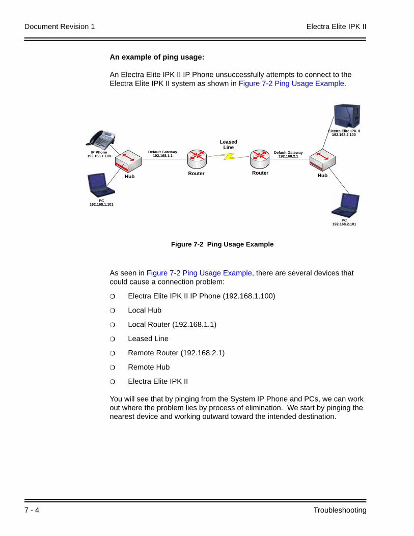
Document Revision 1 Electra Elite IPK II
7 - 4 Troubleshooting
An example of ping usage:
An Electra Elite IPK II IP Phone unsuccessfully attempts to connect to the Electra Elite IPK II system as shown in Figure 7-2 Ping Usage Example.
As seen in Figure 7-2 Ping Usage Example, there are several devices that could cause a connection problem:
Electra Elite IPK II IP Phone (192.168.1.100)
Local Hub
Local Router (192.168.1.1)
Leased Line
Remote Router (192.168.2.1)
Remote Hub
Electra Elite IPK II
You will see that by pinging from the System IP Phone and PCs, we can work out where the problem lies by process of elimination. We start by pinging the nearest device and working outward toward the intended destination.
Figure 7-2 Ping Usage Example
Hub HubRouter Router
Default Gateway192.168.2.1
Default Gateway192.168.1.1
PC192.168.1.101
IP Phone192.168.1.100
Leased Line
Electra Elite IPK II192.168.2.100
PC192.168.2.101
Electra Elite IPK II Document Revision 1
Electra Elite IPK II VoIP Reference Manual 7 - 5
Examples:
The Electra Elite IPK II IP Phone can successfully ping all devices up to and including the local router. Anything beyond that point fails. This would suggest that the Leased Line or remote router has a problem.
The local PC (192.l68.1.101) can ping all devices except the Electra Elite IPK II IP Phone. The Electra Elite IPK II IP Phone can not ping anywhere. This would suggest that there is a problem with the Electra Elite IPK II IP Phone or its connection to the switch/hub.
SECTION 3 PACKET TRACES
It is possible to use a packet trace utility (also known as “Sniffers”) to determine what data is being transmitted and received on an ethernet network. These can be particularly useful to determine the cause of connection issues or voice quality issues.
The packet trace utility has to be run on a PC that is connected to the same hub (not a switched hub) where the Electra Elite IPK II system or Electra Elite IPK II IP Phone is connected.
There are many utilities available that will allow packet trace to be run on a network. One such utility is Ethereal. This is a software application distributed under a GNU general public license (www.ethereal.com). This allows the files to be captured and saved in a standard format for analysis later.
A sample trace file is shown in Figure 7-3 Trace File Example on page 7-6.
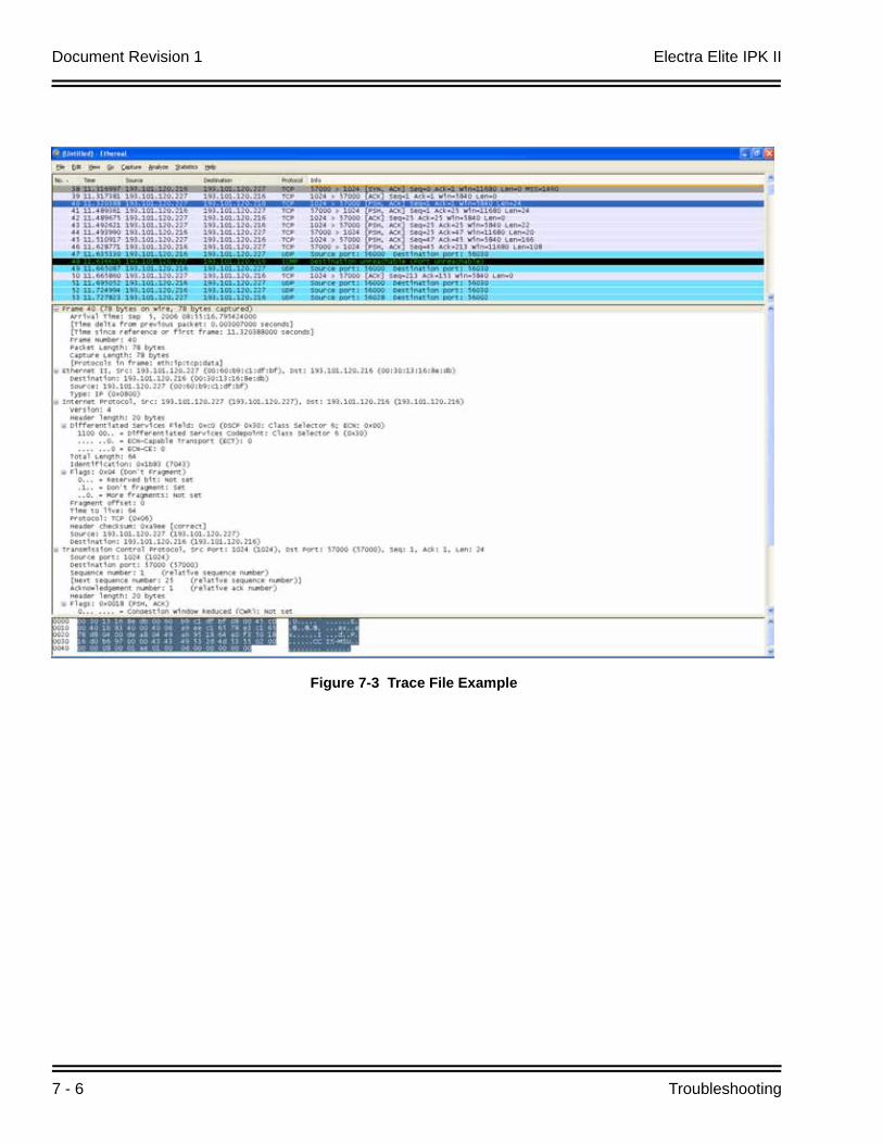
Document Revision 1 Electra Elite IPK II
7 - 6 Troubleshooting
Figure 7-3 Trace File Example

Electra Elite IPK II VoIP Reference Manual 8 - 1
SIP
Tru
nkin
g
8SIP Trunking
SECTION 1 VOIP
VoIP (Voice over Internet Protocol or Voice over IP) allows the delivery of voice information using the Internet protocol (sending data over the Internet using an IP address). This means that voice information, in a digital form, can be sent in packets over the Internet rather than using the traditional public switch telephone network (CO lines). A major advantage of VoIP is that it avoids the tolls charged by ordinary telephone service.
Using VoIP equipment at a gateway (a network point that acts as an entrance to another network), the packetized voice transmissions from users within the company are received and routed to other parts of the company’s intranet (local area or wide area network) or they can be sent over the Internet using CO lines to another gateway. 1
SECTION 2 IP NETWORKING
IP Networking uses VoIP technology to connect two or more telephone systems together. This allows calls to be made between sites without using the public telephone network. This can save a considerable amount of money, and can make communication between sites much easier.
The following Networking modes are available on the Electra Elite IPK II system:
CCISoIP
SIP Trunks
1. The voice quality of VoIP is dependent on variables such as available bandwidth, network latency and Quality ofService (QoS) initiatives, all of which are controlled by the network and internet service providers. Because thesevariables are not in NEC’s control, it cannot guarantee the performance of the user’s IP-based remote voicesolution. Therefore, NEC recommends connecting VoIP equipment through a local area network using a PrivateIP address.
Document Revision 1 Electra Elite IPK II
8 - 2 SIP Trunking
SECTION 3 SIP TRUNKING
3.1 Introduction
SIP (Session Initiation Protocol) is a protocol used for Voice over IP. It is defined by the IETF (Internet Engineering Task Force) in RFC2543 and RFC3261 (RFC3261 requires system software version 1500 or higher). SIP trunking is the term used for linking a PBX, such as the Electra Elite IPK II system, to the public telephone network by means of VoIP. This provides the possibility for users to place and receive communications and services from any location and for networks to identify the users wherever they are located.
SIP analyzes requests from clients and retrieves responses from servers then sets call parameters at either end of the communication, handles call transfer and termination. The Electra Elite IPK II system implementation and programming for SIP are very similar. The call routing, call features and speech handling (RTP) are the same - only the signalling protocol is different.
With the Electra Elite IPK II system, SIP trunks can receive incoming calls with Caller ID, place outgoing calls, and transfer SIP trunks to IP, SIP, analog and digital stations, and across a network.
Currently, however, SIP Centrex Transfer is not supported.
If a common carrier supports SIP, then the Electra Elite IPK II can connect the SIP Carrier and outgoing calls to the PSTN (Public Switched Telephone Network) network and the common IP network using an Electra Elite IPK II SIP trunk.

Electra Elite IPK II Document Revision 1
Electra Elite IPK II VoIP Reference Manual 8 - 3
3.1.1 SIP Trunking Requirements
The following are required when using the SIP trunk on the Electra Elite IPK II system:
Electra Elite IPK II software version 1500 or higher
VOIP ETU [PVA(X)-U10 ETU with MG16 Application 1.50 or higher]
3.1.2 Programming Conditions
The following conditions apply when programming the Electra Elite IPK II system for SIP Trunking:
If entries are made in Program 84-20-xx for a SIP Server and the SIP Server is then removed or not used, the entries in Program 84-20-xx must be set back to their default settings. Even if Program 84-20-01 : SIP Proxy Setup - Outbound Proxy is set to “0” (off), the Electra Elite IPK II system checks the settings in the remaining 84-20 programs.
Figure 8-1 Common IP Network using Electra Elite IPK II SIP Trunk
SIP CARRIER
SIP Registrar
SIP
Dterm IP
NAPT Router
SIP Proxy
DNS
PSTN
Internet/IP VPN
SIP UA
Document Revision 1 Electra Elite IPK II
8 - 4 SIP Trunking
The Electra Elite IPK II system does not support the simultaneous use of a SIP trunk inter-connection and a SIP trunk carrier connection.
The Electra Elite IPK II system restricts an outgoing call under the following conditions:
SIP configuration failedSIP registration failedCPUII/VOIP ETU link downLack of VOIP ETU DSP resourceLack of bandwidth
Electra Elite IPK II system SIP does not support T.38 FAX.
3.1.3 SIP Trunking Setup
Use the following steps to initially set up SIP Trunking for the Electra Elite IPK II system:
1. By default, the Electra Elite IPK II is assigned a static IPaddress and runs behind a NAT router.
When using an Electra Elite IPK II on a LAN behind a NAPT router, forward port 5060 to the IP address of the Electra Elite IPK II CPUII ETU (since the signaling is handled by the CPUII ETU). Then, since the media stream (the speech) uses a large range of ports for the RTP packages, forward the ports (10020~10083) to the IP address of the VoIP ETU. Or, use the DMZ option for the VOIP ETU. This means that the VOIP ETU is not actually behind the firewall. This is achieved by connecting the VOIP ETU to a physical or virtual DMZ port. You can also achieve the same result by port forwarding 10020 to 10083.
2. Define the SIP Carrier account information (user name,password, domain name/IP address to the provider).
3. Define the trunk ports as SIP.
4. Set the Expire Time.
SECTION 4 SIP TRUNK OVERVIEW
This section provides an overview of basic SIP trunk behavior, protocols, supported SIP trunking methods and options, supported CODEC as well as other supported functions of SIP Trunking.
Electra Elite IPK II Document Revision 1
Electra Elite IPK II VoIP Reference Manual 8 - 5
4.1 General Information
The Electra EIite IPK II SIP Trunks behave similarly to some SIP User Agents (UA). UA is the client application used with a particular network protocol.
The Electra elite IPK II provides a maximum of 32 register IDs and can register these IDs with a SIP server.
The maximum number of SIP trunks that can be used with the Electra EIite IPK II system is 200 and the maximum number of simultaneous calls is also 200.
The Electra Elite IPK II can connect a SIP server over a NAPT router by one static global IP address. The Electra Elite IPK II system supports a “DNS resolution access” and a “IP address direct access” for SIP servers and supports the sub-address feature with SIP trunk inter-connection.
4.2 Supported Protocols
The following protocols are supported:
SIP (RFC2543 bis04)
SIP RFC3261 Supported [updated version of RFC2543] (requires software 5.10 or higher)
The SIP stack has been updated from RFC2543 Base to RFC3261 Base.
SDP
RTP/RTCP
UDP
IPv4
4.3 Supported SIP Methods
The following SIP methods are supported with the Electra Elite IPK II system:
REGISTER
INVITE
BYE
CANCEL
ACK
PRACK
Response 1xx 2xx, 3xx, 4xx, 5xx, 6xx
Document Revision 1 Electra Elite IPK II
8 - 6 SIP Trunking
The following features are available:
Support the 401 response for the Initial InviteIf 401 message is sent for the Initial Invite, with previous software, the system can not respond to the message correctly.
Support the 401/407 response for the Invite of Session TimerIf 401/407 response is sent for the invite of Session Timer, the system can send the Invite message with Authentication header.
Support the 128 byte size of Nonce max value sent by the 401/407 messageThe Nonce maximum size sent by the 401/407 message is expanded to 128 byte. With previous software, 64 byte size can be received.
4.4 Supported SIP Trunking Options
The options listed below are supported with SIP Trunking.
100rel
Session Timer
Early Media
4.5 Supported CODEC
SIP Trunking can use the following CODECs.
G.711u-law/A-lawVAD [Voice Activity Detection (Silence Detection)]VIF [Voice Information Field (Frame size)]size 20ms~30msWhen using 10ms, the Electra Elite IPK II system requires the VOIP ETU.
G.729, VAD, VIF size 20ms~30ms
These settings can be changed using Program 84-13-xx.For example:Audio CODEC priority - 84-13-28u-law/A-law - 84-13-03Frame size(G.711) - 84-13-01
Electra Elite IPK II Document Revision 1
Electra Elite IPK II VoIP Reference Manual 8 - 7
SECTION 5 SUPPORTED SIP TRUNKING FUNCTIONS
The functions in this section are supported by Electra Elite IPK II SIP Trunking.
5.1 Address Resolution
If using a SIP Proxy Server, the Electra Elite IPK II always sends messages to an external SIP server.
If not using a SIP Proxy Server, the Electra Elite IPK II uses the internal address table (Program 10-23 : SIP System Interconnection Setup).
When a user creates an inter-connection network with SIP trunks, Program 10-29-14 : SIP Server Information Setup - SIP Carrier Choice must be set to “0” (default).
5.2 Authentication Process
When using an external SIP Server provided by a carrier, an authentication process is usually needed.
Electra Elite IPK II SIP trunks support HTTP digest authentication process (MD5). This process is done on a Register process and Initial INVITE process.
5.3 Caller ID
Caller ID for SIP Trunks is set by Program 21-17 : IP Trunk (SIP) Calling Party Number Setup for Trunk.
Caller ID for SIP Extensions is Program 21-19 : IP Trunk (SIP) Calling Party Number Setup for Extension.
Programs follow program priority as follows: 21-19 > 21-17 > 10-28-04
With a trunk-to-trunk transfer and Trunk-to-Trunk Outgoing Caller ID Through Mode enabled (Program 14-01-24), the Caller ID/sub-address (received from the incoming trunk) will be sent. If a SIP trunk is connected to a SIP carrier, then the sub-address is not transferred.
Document Revision 1 Electra Elite IPK II
8 - 8 SIP Trunking
5.4 Carrier Support
If a common carrier supports SIP, the Electra Elite IPK II can connect:
the SIP Carrier
the outgoing call to the PSTN network
the common IP network via an Electra Elite IPK II SIP trunk.
A conformity test with a carrier’s SIP server is recommended.
5.5 Early Media
When the Electra Elite IPK II receives the response 18x w/SDP and the codec negotiation is a success, the Electra Elite IPK II starts to send/receive RTP packets.
5.6 Fault Tolerance
When the Electra Elite IPK II uses an external SIP Server and if the registration process fails, the Electra Elite IPK II blocks outgoing calls with SIP trunks. All SIP trunk ports are placed into a busy status.
If the Electra Elite IPK II has trunk groups that include both SIP trunks and ISDN trunks, and all SIP trunks are busy, a user can make an outgoing call using an ISDN trunk as a bypass.
5.7 Network Address Port Translation (NAPT)
Electra Elite IPK II SIP trunk can pass through a NAPT router. The related system data is Program 10-12-06 : CPUII Network Setup - NAPT Router (On/Off) and Program 10-12-07 : CPUII Network Setup - NAPT Router IP Address (do not set with a dynamic router IP address).
Incorrect settings with these two programs can cause one-way audio problems.
The WAN global IP is set in the system data by the user or automatically using the NAT traversal feature (UPnP). The related system data is 10-37-01 : UPnP Setup - UPnP Mode (On/Off) and 10-37-02 : UPnP Setup - UPnP Interval (polling timer).
5.8 Quality of Service (QoS)
Electra Elite IPK II SIP trunks support Type of Service (ToS) (Program 84-10 : ToS Setup, protocol type=6 (SIP Trunk).
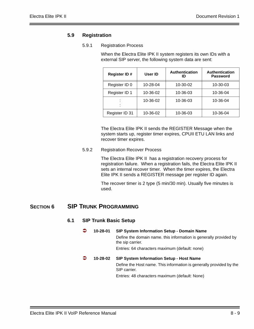
Electra Elite IPK II Document Revision 1
Electra Elite IPK II VoIP Reference Manual 8 - 9
5.9 Registration
5.9.1 Registration Process
When the Electra Elite IPK II system registers its own IDs with a external SIP server, the following system data are sent:
The Electra Elite IPK II sends the REGISTER Message when the system starts up, register timer expires, CPUII ETU LAN links and recover timer expires.
5.9.2 Registration Recover Process
The Electra Elite IPK II has a registration recovery process for registration failure. When a registration fails, the Electra Elite IPK II sets an internal recover timer. When the timer expires, the Electra Elite IPK II sends a REGISTER message per register ID again.
The recover timer is 2 type (5 min/30 min). Usually five minutes is used.
SECTION 6 SIP TRUNK PROGRAMMING
6.1 SIP Trunk Basic Setup
10-28-01 SIP System Information Setup - Domain NameDefine the domain name. this information is generally provided by the sip carrier. Entries: 64 characters maximum (default: none)
10-28-02 SIP System Information Setup - Host NameDefine the Host name. This information is generally provided by the SIP carrier.Entries: 48 characters maximum (default: None)
Register ID # User ID Authentication ID
Authentication Password
Register ID 0 10-28-04 10-30-02 10-30-03
Register ID 1 10-36-02 10-36-03 10-36-04
::
10-36-02 10-36-03 10-36-04
Register ID 31 10-36-02 10-36-03 10-36-04
Document Revision 1 Electra Elite IPK II
8 - 10 SIP Trunking
10-28-03 SIP System Information Setup - Transport ProtocolDefine the Transport type. This option will always be set to UDP.Entries: 0=UDP, 1=TCP (default: 0=UDP)
10-28-04 SIP System Information Setup - User IDDefine the User ID.
If Program 10-23-04 for system interconnection, this entry must be numeric as 10-23-04 does not allow text entry - only numeric. This information is generally provided by the SIP carrier.
Entries: 32 characters maximum (default=No Entry)
10-28-05 SIP System Information Setup - Domain AssignmentDefine the Domain Assignment. This entry is determined by what information the SIP carrier provides. If the SIP carrier provides a server name: [email protected], then the domain would be:@L0.cbeyond.net and the host name would be SIPconnect-sca.Entries: 0=IP Address, 1=Domain Name (default: 0=IP Address)
10-29-14 SIP Server Information Setup - SIP Carrier ChoiceDefine the SIP Carrier Choice. This should currently stay at an entry of “0” (default).Entries: 0=Default, 1=Carrier A, 2=Carrier B, 3=Carrier C, 4=Carrier D, 5=Carrier E, 6=Carrier F, 7=Carrier G (default: 0)
10-40-01 SIP Trunk Availability - SIP Trunk AvailabilityDetermines SIP Trunk availability.Entries: 0=Disable, 1=Enable (default: 0)
10-40-02 SIP Trunk Availability - Number of PortsDetermine the IP trunk type setup. With SIP trunking, some ports must be defined for SIP.Entries: 0=4 Ports, 1=8 Ports, 2=12 Ports, 3=16 Ports (default: None)
22-02-01 Incoming Call Trunk SetupDefine the SIP trunks as type “3” (DID). In addition to the SIP trunk programming, refer to the Direct Inward Dialing (DID) feature in the Electra Elite IPK Features and Specifications Manuals and the Electra Elite IPK II Programming Manual for detailed information.
Electra Elite IPK II Document Revision 1
Electra Elite IPK II VoIP Reference Manual 8 - 11
6.2 IP DSP Resource
10-19-01 VOIP DSP Resource SelectionSelect the type of VOIP ETU DSP Resource. This program setting has no affect on the terminal/trunk port assignments or usage.Entries: 0=Common (Used for both IP Extensions and Trunks), 1=Extension, 2=Trunk, 3=Networking (default: 0)
6.3 SIP Authentication Information
10-30-02 SIP Authentication Information - User NameDefine the authentication User name provided by the SIP carrier.Entries: 48 characters maximum (default: None)
10-30-03 SIP Authentication Information - PasswordEnter the authentication password provided by the SIP carrier. When the Electra Elite IPK II registers its own ID with the carrier SIP server or makes an outgoing call via the carrier SIP server, the SIP server requests the authentication. This data is used as "Register ID 0".Entries: 24 characters maximum (default: None)
10-30-04 SIP Authentication Information - Authentication TrialDefine the Authorization Trial. When a call tries to register with the SIP carrier and they refuse, this entry determines how many times the Electra Elite IPK II will send authorization.Entries: 1~9 (default:1 time)
6.4 SIP Caller ID
14-01-24 Basic Trunk Data Setup - Trunk-to-Trunk Outgoing Caller ID Through ModeEnable or disable the Trunk-to-Trunk Outgoing Caller ID Through Mode. This option allows Caller ID from the original outside caller to be displayed when a trunk is forwarded off premise. This option can only be used with PRI and SIP trunks.Entries: 0=Disabled, 1=Enabled (default: 0)
21-17-01 IP Trunk (SIP) Calling Party Number Setup for TrunkThis program assigns the Caller Party Number for each IP trunk. The assigned number is sent to the central office when the caller places an outgoing call. If the Calling Party Number is assigned by both 21-17 and 21-18/21-19, then the system uses the entry in 21-18/21-19.Entries: 1~0, , # (to equal up to 16 digits) (default: None)
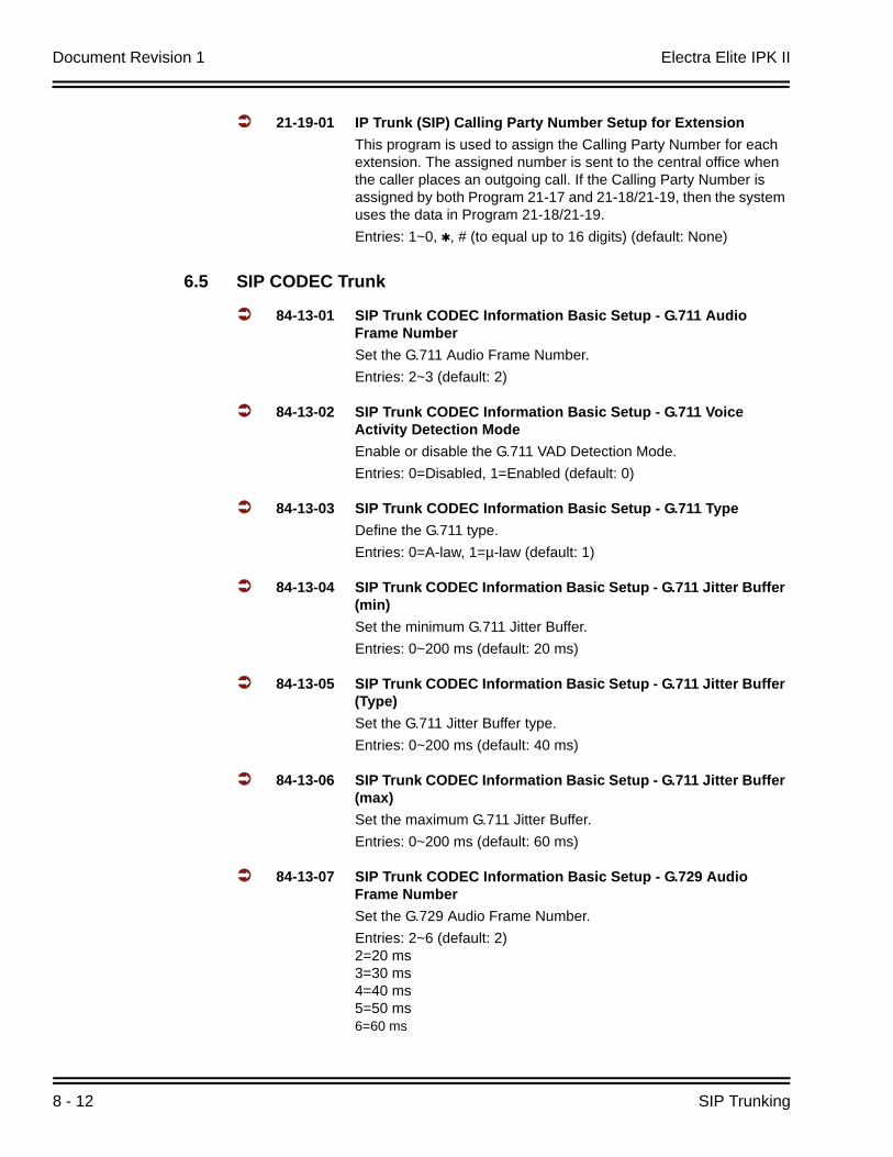
Document Revision 1 Electra Elite IPK II
8 - 12 SIP Trunking
21-19-01 IP Trunk (SIP) Calling Party Number Setup for ExtensionThis program is used to assign the Calling Party Number for each extension. The assigned number is sent to the central office when the caller places an outgoing call. If the Calling Party Number is assigned by both Program 21-17 and 21-18/21-19, then the system uses the data in Program 21-18/21-19.Entries: 1~0, , # (to equal up to 16 digits) (default: None)
6.5 SIP CODEC Trunk
84-13-01 SIP Trunk CODEC Information Basic Setup - G.711 Audio Frame NumberSet the G.711 Audio Frame Number.Entries: 2~3 (default: 2)
84-13-02 SIP Trunk CODEC Information Basic Setup - G.711 Voice Activity Detection ModeEnable or disable the G.711 VAD Detection Mode.Entries: 0=Disabled, 1=Enabled (default: 0)
84-13-03 SIP Trunk CODEC Information Basic Setup - G.711 TypeDefine the G.711 type.Entries: 0=A-law, 1=µ-law (default: 1)
84-13-04 SIP Trunk CODEC Information Basic Setup - G.711 Jitter Buffer (min)Set the minimum G.711 Jitter Buffer.Entries: 0~200 ms (default: 20 ms)
84-13-05 SIP Trunk CODEC Information Basic Setup - G.711 Jitter Buffer (Type)Set the G.711 Jitter Buffer type.Entries: 0~200 ms (default: 40 ms)
84-13-06 SIP Trunk CODEC Information Basic Setup - G.711 Jitter Buffer (max)Set the maximum G.711 Jitter Buffer.Entries: 0~200 ms (default: 60 ms)
84-13-07 SIP Trunk CODEC Information Basic Setup - G.729 Audio Frame NumberSet the G.729 Audio Frame Number.Entries: 2~6 (default: 2) 2=20 ms3=30 ms4=40 ms5=50 ms6=60 ms
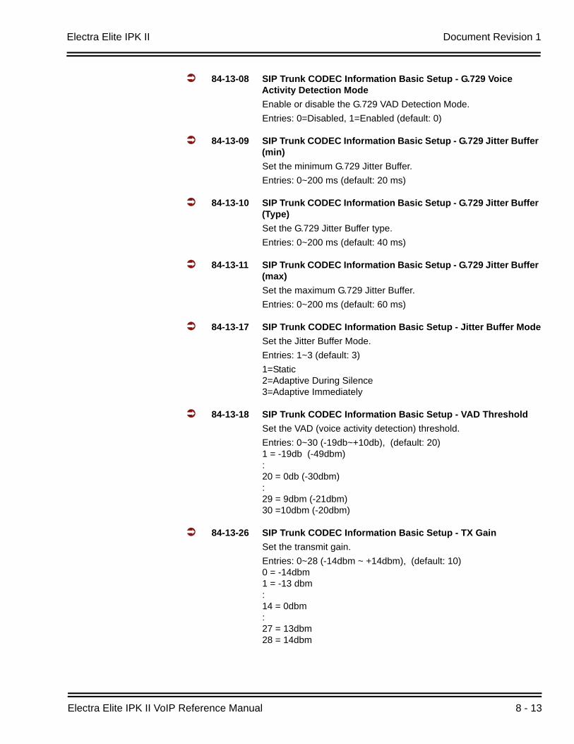
Electra Elite IPK II Document Revision 1
Electra Elite IPK II VoIP Reference Manual 8 - 13
84-13-08 SIP Trunk CODEC Information Basic Setup - G.729 Voice Activity Detection ModeEnable or disable the G.729 VAD Detection Mode.Entries: 0=Disabled, 1=Enabled (default: 0)
84-13-09 SIP Trunk CODEC Information Basic Setup - G.729 Jitter Buffer (min)Set the minimum G.729 Jitter Buffer.Entries: 0~200 ms (default: 20 ms)
84-13-10 SIP Trunk CODEC Information Basic Setup - G.729 Jitter Buffer (Type)Set the G.729 Jitter Buffer type.Entries: 0~200 ms (default: 40 ms)
84-13-11 SIP Trunk CODEC Information Basic Setup - G.729 Jitter Buffer (max)Set the maximum G.729 Jitter Buffer.Entries: 0~200 ms (default: 60 ms)
84-13-17 SIP Trunk CODEC Information Basic Setup - Jitter Buffer ModeSet the Jitter Buffer Mode.Entries: 1~3 (default: 3)1=Static2=Adaptive During Silence3=Adaptive Immediately
84-13-18 SIP Trunk CODEC Information Basic Setup - VAD ThresholdSet the VAD (voice activity detection) threshold.Entries: 0~30 (-19db~+10db), (default: 20)1 = -19db (-49dbm):20 = 0db (-30dbm):29 = 9dbm (-21dbm)30 =10dbm (-20dbm)
84-13-26 SIP Trunk CODEC Information Basic Setup - TX GainSet the transmit gain.Entries: 0~28 (-14dbm ~ +14dbm), (default: 10)0 = -14dbm1 = -13 dbm:14 = 0dbm:27 = 13dbm28 = 14dbm
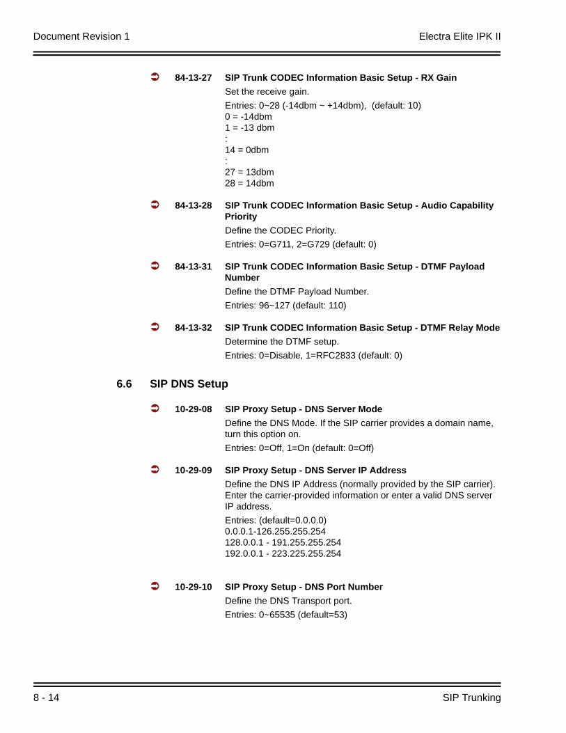
Document Revision 1 Electra Elite IPK II
8 - 14 SIP Trunking
84-13-27 SIP Trunk CODEC Information Basic Setup - RX GainSet the receive gain.Entries: 0~28 (-14dbm ~ +14dbm), (default: 10)0 = -14dbm1 = -13 dbm:14 = 0dbm:27 = 13dbm28 = 14dbm
84-13-28 SIP Trunk CODEC Information Basic Setup - Audio Capability PriorityDefine the CODEC Priority.Entries: 0=G711, 2=G729 (default: 0)
84-13-31 SIP Trunk CODEC Information Basic Setup - DTMF Payload NumberDefine the DTMF Payload Number.Entries: 96~127 (default: 110)
84-13-32 SIP Trunk CODEC Information Basic Setup - DTMF Relay ModeDetermine the DTMF setup.Entries: 0=Disable, 1=RFC2833 (default: 0)
6.6 SIP DNS Setup
10-29-08 SIP Proxy Setup - DNS Server ModeDefine the DNS Mode. If the SIP carrier provides a domain name, turn this option on.Entries: 0=Off, 1=On (default: 0=Off)
10-29-09 SIP Proxy Setup - DNS Server IP AddressDefine the DNS IP Address (normally provided by the SIP carrier). Enter the carrier-provided information or enter a valid DNS server IP address.Entries: (default=0.0.0.0)0.0.0.1-126.255.255.254128.0.0.1 - 191.255.255.254192.0.0.1 - 223.225.255.254
10-29-10 SIP Proxy Setup - DNS Port NumberDefine the DNS Transport port.Entries: 0~65535 (default=53)
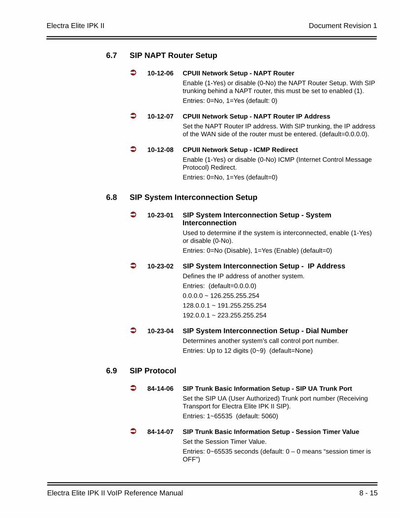
Electra Elite IPK II Document Revision 1
Electra Elite IPK II VoIP Reference Manual 8 - 15
6.7 SIP NAPT Router Setup
10-12-06 CPUII Network Setup - NAPT RouterEnable (1-Yes) or disable (0-No) the NAPT Router Setup. With SIP trunking behind a NAPT router, this must be set to enabled (1).Entries: 0=No, 1=Yes (default: 0)
10-12-07 CPUII Network Setup - NAPT Router IP AddressSet the NAPT Router IP address. With SIP trunking, the IP address of the WAN side of the router must be entered. (default=0.0.0.0).
10-12-08 CPUII Network Setup - ICMP RedirectEnable (1-Yes) or disable (0-No) ICMP (Internet Control Message Protocol) Redirect.Entries: 0=No, 1=Yes (default=0)
6.8 SIP System Interconnection Setup
10-23-01 SIP System Interconnection Setup - System InterconnectionUsed to determine if the system is interconnected, enable (1-Yes) or disable (0-No).Entries: 0=No (Disable), 1=Yes (Enable) (default=0)
10-23-02 SIP System Interconnection Setup - IP AddressDefines the IP address of another system.Entries: (default=0.0.0.0)0.0.0.0 ~ 126.255.255.254 128.0.0.1 ~ 191.255.255.254192.0.0.1 ~ 223.255.255.254
10-23-04 SIP System Interconnection Setup - Dial NumberDetermines another system’s call control port number. Entries: Up to 12 digits (0~9) (default=None)
6.9 SIP Protocol
84-14-06 SIP Trunk Basic Information Setup - SIP UA Trunk PortSet the SIP UA (User Authorized) Trunk port number (Receiving Transport for Electra Elite IPK II SIP).Entries: 1~65535 (default: 5060)
84-14-07 SIP Trunk Basic Information Setup - Session Timer ValueSet the Session Timer Value.Entries: 0~65535 seconds (default: 0 – 0 means “session timer is OFF”)
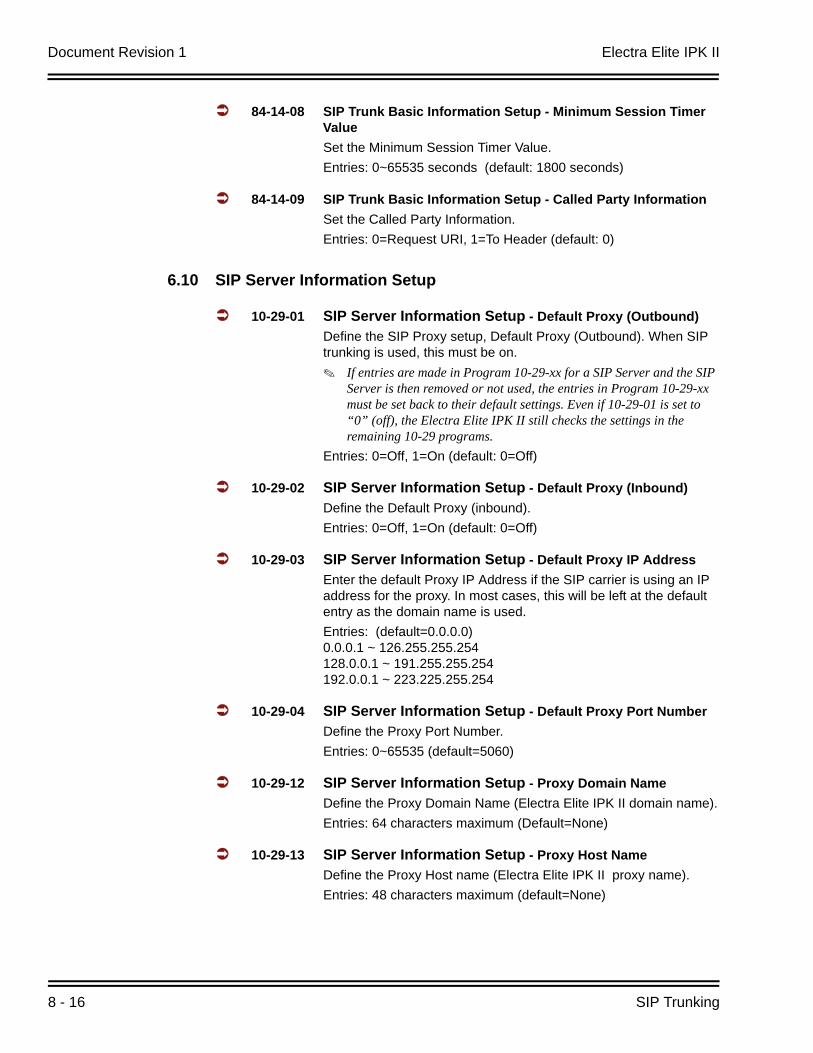
Document Revision 1 Electra Elite IPK II
8 - 16 SIP Trunking
84-14-08 SIP Trunk Basic Information Setup - Minimum Session Timer ValueSet the Minimum Session Timer Value.Entries: 0~65535 seconds (default: 1800 seconds)
84-14-09 SIP Trunk Basic Information Setup - Called Party InformationSet the Called Party Information.Entries: 0=Request URI, 1=To Header (default: 0)
6.10 SIP Server Information Setup
10-29-01 SIP Server Information Setup - Default Proxy (Outbound)Define the SIP Proxy setup, Default Proxy (Outbound). When SIP trunking is used, this must be on.
If entries are made in Program 10-29-xx for a SIP Server and the SIP Server is then removed or not used, the entries in Program 10-29-xx must be set back to their default settings. Even if 10-29-01 is set to “0” (off), the Electra Elite IPK II still checks the settings in the remaining 10-29 programs.
Entries: 0=Off, 1=On (default: 0=Off)
10-29-02 SIP Server Information Setup - Default Proxy (Inbound)Define the Default Proxy (inbound).Entries: 0=Off, 1=On (default: 0=Off)
10-29-03 SIP Server Information Setup - Default Proxy IP AddressEnter the default Proxy IP Address if the SIP carrier is using an IP address for the proxy. In most cases, this will be left at the default entry as the domain name is used.Entries: (default=0.0.0.0)0.0.0.1 ~ 126.255.255.254128.0.0.1 ~ 191.255.255.254192.0.0.1 ~ 223.225.255.254
10-29-04 SIP Server Information Setup - Default Proxy Port NumberDefine the Proxy Port Number.Entries: 0~65535 (default=5060)
10-29-12 SIP Server Information Setup - Proxy Domain NameDefine the Proxy Domain Name (Electra Elite IPK II domain name).Entries: 64 characters maximum (Default=None)
10-29-13 SIP Server Information Setup - Proxy Host NameDefine the Proxy Host name (Electra Elite IPK II proxy name).Entries: 48 characters maximum (default=None)
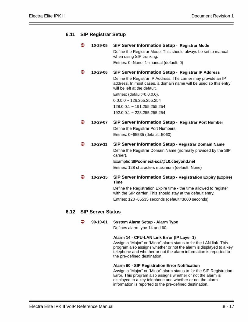
Electra Elite IPK II Document Revision 1
Electra Elite IPK II VoIP Reference Manual 8 - 17
6.11 SIP Registrar Setup
10-29-05 SIP Server Information Setup - Registrar ModeDefine the Registrar Mode. This should always be set to manual when using SIP trunking.Entries: 0=None, 1=manual (default: 0)
10-29-06 SIP Server Information Setup - Registrar IP AddressDefine the Registrar IP Address. The carrier may provide an IP address. In most cases, a domain name will be used so this entry will be left at the default. Entries: (default=0.0.0.0).0.0.0.0 ~ 126.255.255.254 128.0.0.1 ~ 191.255.255.254192.0.0.1 ~ 223.255.255.254
10-29-07 SIP Server Information Setup - Registrar Port NumberDefine the Registrar Port Numbers.Entries: 0~65535 (default=5060)
10-29-11 SIP Server Information Setup - Registrar Domain NameDefine the Registrar Domain Name (normally provided by the SIP carrier). Example: [email protected]: 128 characters maximum (default=None)
10-29-15 SIP Server Information Setup - Registration Expiry (Expire) TimeDefine the Registration Expire time - the time allowed to register with the SIP carrier. This should stay at the default entry.Entries: 120~65535 seconds (default=3600 seconds)
6.12 SIP Server Status
90-10-01 System Alarm Setup - Alarm TypeDefines alarm type 14 and 60.
Alarm 14 - CPU-LAN Link Error (IP Layer 1)Assign a “Major” or “Minor” alarm status to for the LAN link. This program also assigns whether or not the alarm is displayed to a key telephone and whether or not the alarm information is reported to the pre-defined destination.
Alarm 60 - SIP Registration Error NotificationAssign a “Major” or “Minor” alarm status to for the SIP Registration Error. This program also assigns whether or not the alarm is displayed to a key telephone and whether or not the alarm information is reported to the pre-defined destination.
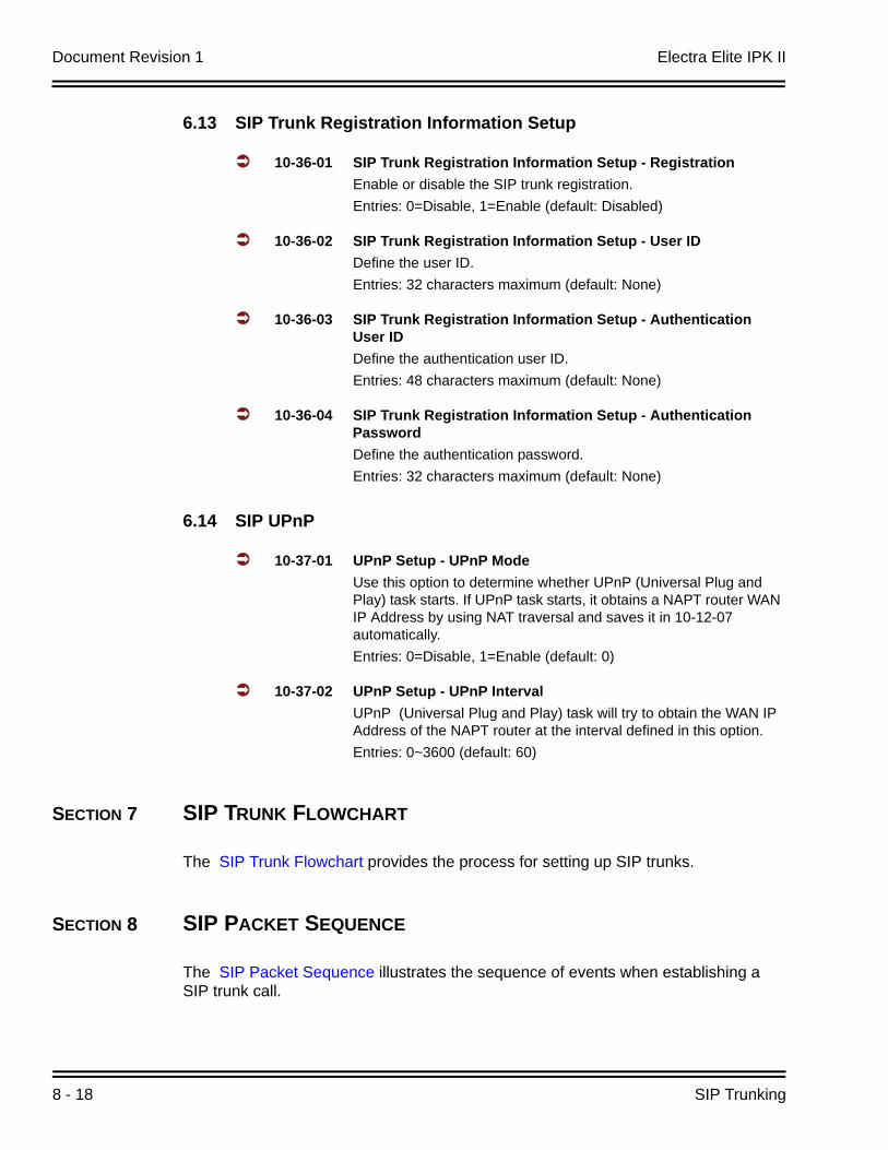
Document Revision 1 Electra Elite IPK II
8 - 18 SIP Trunking
6.13 SIP Trunk Registration Information Setup
10-36-01 SIP Trunk Registration Information Setup - RegistrationEnable or disable the SIP trunk registration.Entries: 0=Disable, 1=Enable (default: Disabled)
10-36-02 SIP Trunk Registration Information Setup - User IDDefine the user ID.Entries: 32 characters maximum (default: None)
10-36-03 SIP Trunk Registration Information Setup - Authentication User IDDefine the authentication user ID.Entries: 48 characters maximum (default: None)
10-36-04 SIP Trunk Registration Information Setup - Authentication PasswordDefine the authentication password.Entries: 32 characters maximum (default: None)
6.14 SIP UPnP
10-37-01 UPnP Setup - UPnP ModeUse this option to determine whether UPnP (Universal Plug and Play) task starts. If UPnP task starts, it obtains a NAPT router WAN IP Address by using NAT traversal and saves it in 10-12-07 automatically.Entries: 0=Disable, 1=Enable (default: 0)
10-37-02 UPnP Setup - UPnP IntervalUPnP (Universal Plug and Play) task will try to obtain the WAN IP Address of the NAPT router at the interval defined in this option.Entries: 0~3600 (default: 60)
SECTION 7 SIP TRUNK FLOWCHART
The SIP Trunk Flowchart provides the process for setting up SIP trunks.
SECTION 8 SIP PACKET SEQUENCE
The SIP Packet Sequence illustrates the sequence of events when establishing a SIP trunk call.
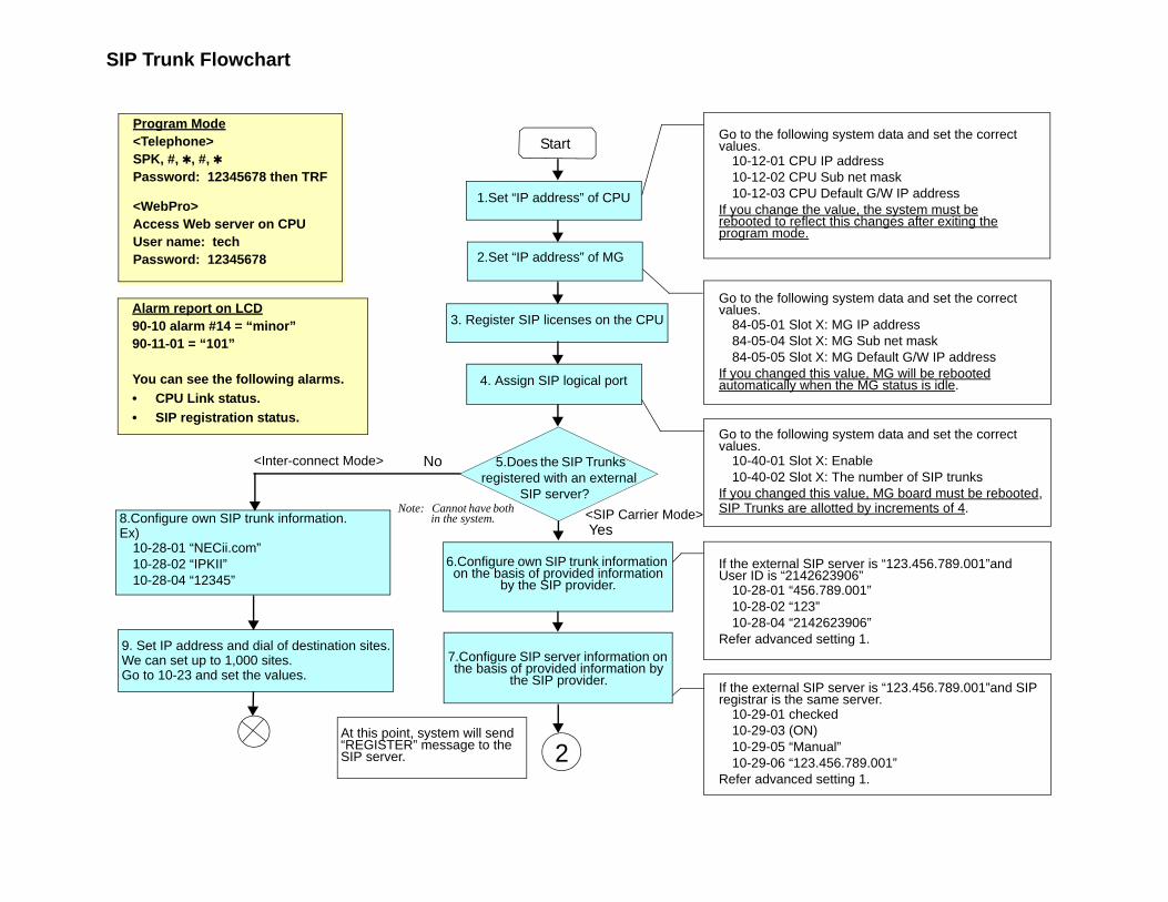
SIP Trunk Flowchart
<Inter-connect Mode>
<SIP Carrier Mode>
No
2
Go to the following system data and set the correct values.
10-12-01 CPU IP address10-12-02 CPU Sub net mask10-12-03 CPU Default G/W IP address
If you change the value, the system must berebooted to reflect this changes after exiting theprogram mode.
Yes
Go to the following system data and set the correct values.
84-05-01 Slot X: MG IP address84-05-04 Slot X: MG Sub net mask84-05-05 Slot X: MG Default G/W IP address
If you changed this value, MG will be rebootedautomatically when the MG status is idle.
Go to the following system data and set the correct values.
10-40-01 Slot X: Enable10-40-02 Slot X: The number of SIP trunks
If you changed this value, MG board must be rebooted,SIP Trunks are allotted by increments of 4.
If the external SIP server is “123.456.789.001”and User ID is “2142623906”
10-28-01 “456.789.001”10-28-02 “123”10-28-04 “2142623906”
Refer advanced setting 1.
If the external SIP server is “123.456.789.001”and SIP registrar is the same server.
10-29-01 checked10-29-03 (ON)10-29-05 “Manual”10-29-06 “123.456.789.001”
Refer advanced setting 1.
Start
2.Set “IP address” of MG
3. Register SIP licenses on the CPU
4. Assign SIP logical port
5.Does the SIP Trunks registered with an external
SIP server?
6.Configure own SIP trunk information on the basis of provided information
by the SIP provider.
7.Configure SIP server information on the basis of provided information by
the SIP provider.
At this point, system will send “REGISTER” message to the SIP server.
8.Configure own SIP trunk information.Ex)
10-28-01 “NECii.com”10-28-02 “IPKII”10-28-04 “12345”
9. Set IP address and dial of destination sites.We can set up to 1,000 sites. Go to 10-23 and set the values.
Alarm report on LCD90-10 alarm #14 = “minor”90-11-01 = “101”
You can see the following alarms.• CPU Link status.• SIP registration status.
1.Set “IP address” of CPU
Program Mode<Telephone>SPK, #, , #, Password: 12345678 then TRF
<WebPro>Access Web server on CPUUser name: techPassword: 12345678
Note: Cannot have both in the system.
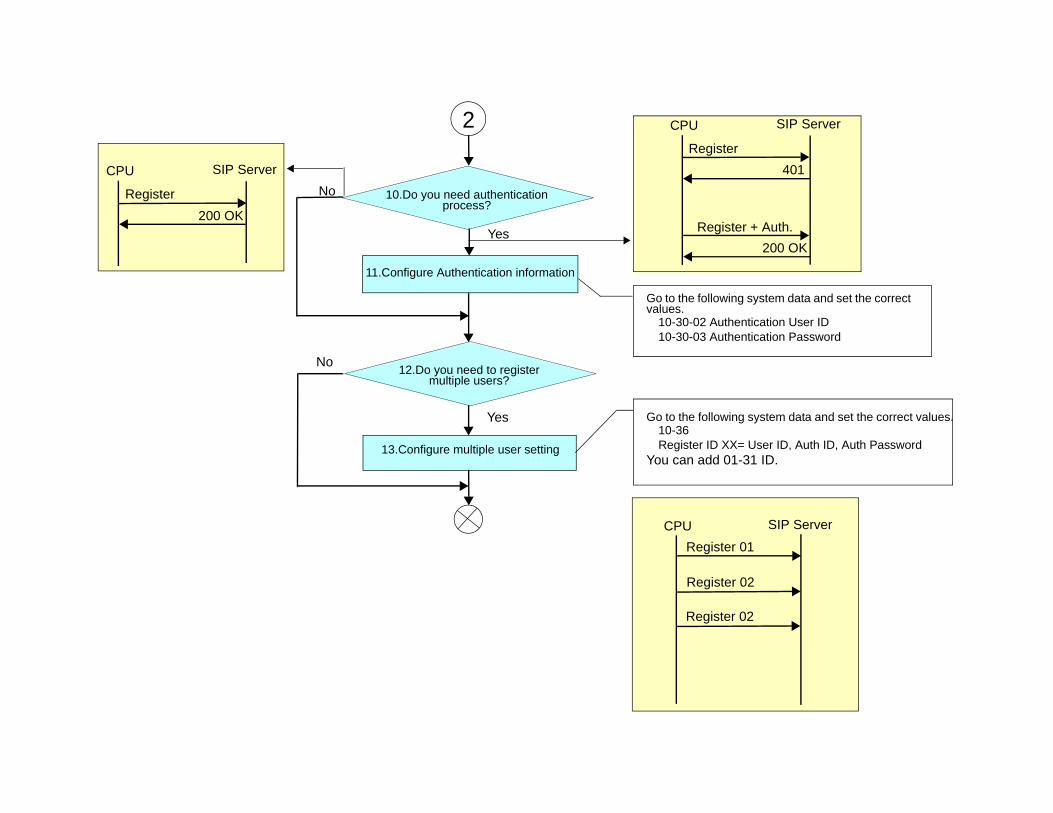
No
Yes
Yes
No
2
10.Do you need authentication process?
11.Configure Authentication information
12.Do you need to register multiple users?
13.Configure multiple user setting
CPU SIP Server
Register401
Register + Auth.200 OK
CPU SIP Server
Register200 OK
Go to the following system data and set the correct values.
10-30-02 Authentication User ID10-30-03 Authentication Password
Go to the following system data and set the correct values.10-36Register ID XX= User ID, Auth ID, Auth Password
You can add 01-31 ID.
CPU SIP Server
Register 01
Register 02
Register 02
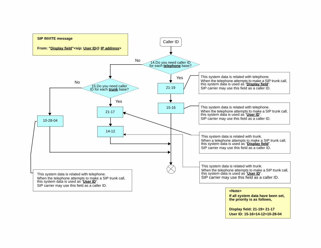
Caller ID
This system data is related with telephone.When the telephone attempts to make a SIP trunk call, this system data is used as “Display field”.SIP carrier may use this field as a caller ID.
This system data is related with telephone.When the telephone attempts to make a SIP trunk call, this system data is used as “User ID”.SIP carrier may use this field as a caller ID.
14.Do you need caller ID for each telephone base?
21-19
15-16 21-17
14-12
10-28-04
This system data is related with telephone.When the telephone attempts to make a SIP trunk call, this system data is used as “User ID”.SIP carrier may use this field as a caller ID.
SIP INVITE message
From: “Display field”<sip: User ID@ IP address>
Yes
Yes
No
No15.Do you need caller
ID for each trunk base?
<Note>If all system data have been set, the priority is as follows,
Display field: 21-19> 21-17User ID: 15-16>14-12>10-28-04
This system data is related with trunk.When a telephone attempts to make a SIP trunk call, this system data is used as “Display field”.SIP carrier may use this field as a caller ID.
This system data is related with trunk.When the telephone attempts to make a SIP trunk call, this system data is used as “User ID”.SIP carrier may use this field as a caller ID.
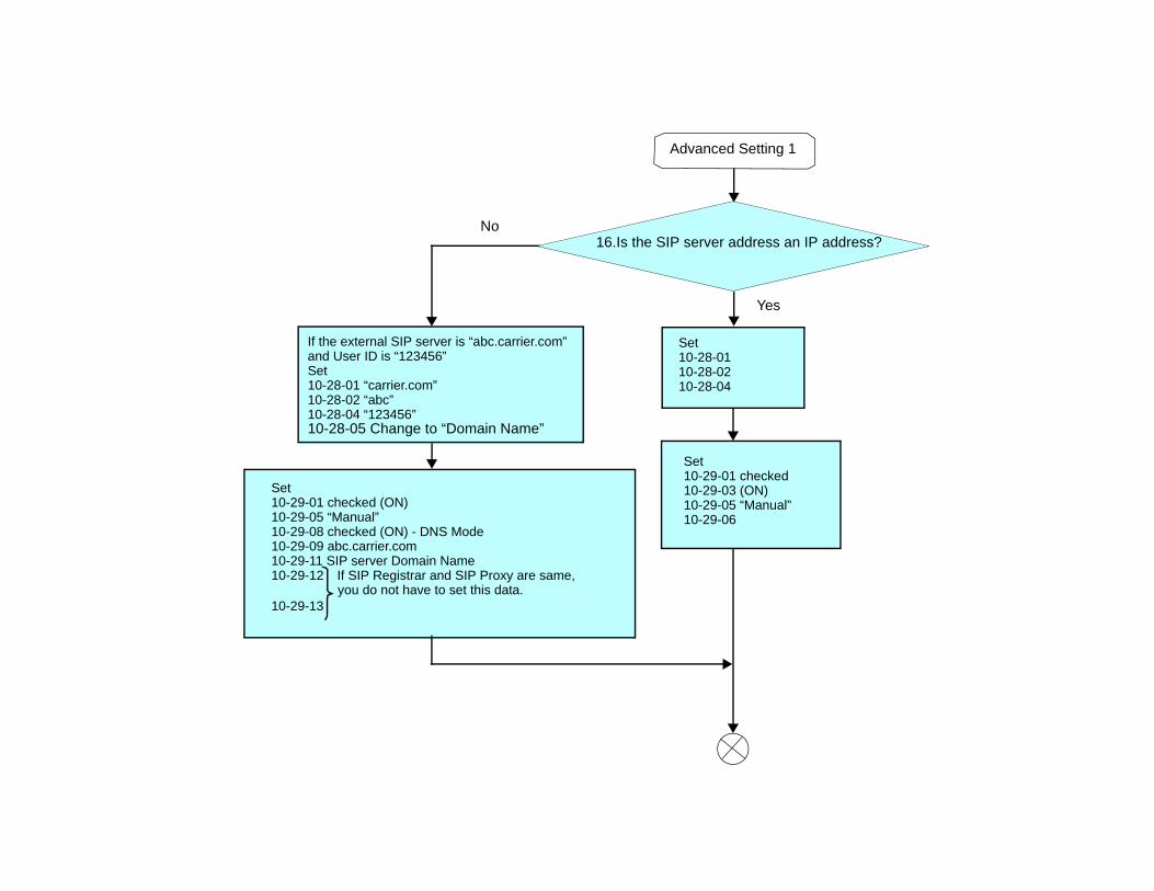
No
Yes
Advanced Setting 1
16.Is the SIP server address an IP address?
If the external SIP server is “abc.carrier.com”and User ID is “123456”Set 10-28-01 “carrier.com”10-28-02 “abc”10-28-04 “123456”10-28-05 Change to “Domain Name”
Set10-29-01 checked (ON)10-29-05 “Manual”10-29-08 checked (ON) - DNS Mode10-29-09 abc.carrier.com10-29-11 SIP server Domain Name10-29-12 If SIP Registrar and SIP Proxy are same,
you do not have to set this data.10-29-13
Set 10-28-0110-28-0210-28-04
Set 10-29-01 checked10-29-03 (ON)10-29-05 “Manual”10-29-06
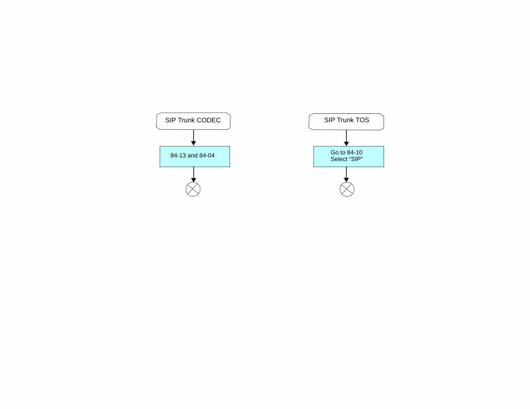
SIP Trunk CODEC SIP Trunk TOS
84-13 and 84-04 Go to 84-10Select “SIP”
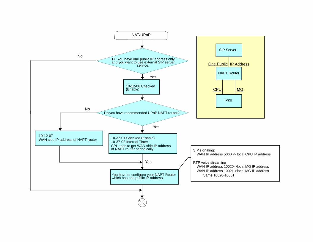
CPU MG
One Public IP Address
SIP Server
NAPT Router
IPKII
NAT/UPnP
Yes
No
No
Yes
17. You have one public IP address only and you want to use external SIP server
service.
10-12-06 Checked (Enable)
Do you have recommended UPnP NAPT router?
10-12-07 WAN side IP address of NAPT router
You have to configure your NAPT Router which has one public IP address.
SIP signaling:WAN IP address 5060 -> local CPU IP address
RTP voice streamingWAN IP address 10020->local MG IP addressWAN IP address 10021->local MG IP address
Same 10020-10051
Yes
10-37-01 Checked (Enable)10-37-02 Internal TimerCPU tries to get WAN side IP address of NAPT router periodically.
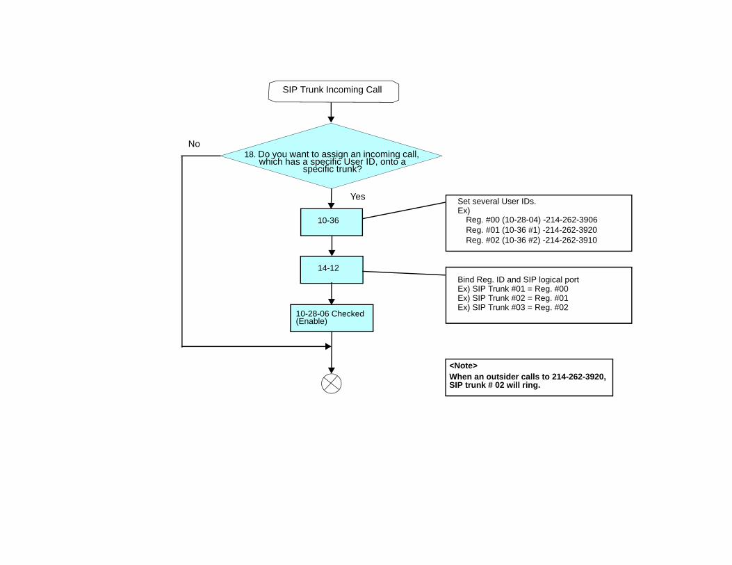
SIP Trunk Incoming Call
18. Do you want to assign an incoming call, which has a specific User ID, onto a
specific trunk?
10-36
14-12
10-28-06 Checked (Enable)
Set several User IDs.Ex)
Reg. #00 (10-28-04) -214-262-3906Reg. #01 (10-36 #1) -214-262-3920Reg. #02 (10-36 #2) -214-262-3910
Bind Reg. ID and SIP logical portEx) SIP Trunk #01 = Reg. #00Ex) SIP Trunk #02 = Reg. #01Ex) SIP Trunk #03 = Reg. #02
No
Yes
<Note>When an outsider calls to 214-262-3920, SIP trunk # 02 will ring.
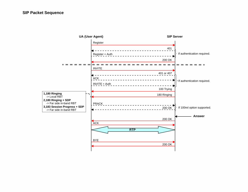
SIP Packet Sequence
1,180 Ringing-> Local RBT
2,180 Ringing + SDP-> Far side in-band RBT
3,183 Session Progress + SDP-> Far side in-band RBT
BYE
ACK
ACK
200 OK
PRACK
INVITE + Auth
INVITE
Register + Auth
Register
401
200 OK
200 OK
200 OK
401 or 407
100 Trying
180 Ringing
If authentication required.
If authentication required.
If 100rel option supported.
UA (User Agent) SIP Server
Answer
RTP
Electra Elite IPK II VoIP Reference Manual 9 - 1
SIP
Statio
n
9SIP Station
SECTION 1 INTRODUCTION
SIP (Session Initiation Protocol) is a protocol used for Voice over Internet Protocol (VoIP). It is defined by the IETF (Internet Engineering Task Force) RFC3261. Commonly known as SIP Station, this feature is used for IP Stations utilizing Session Initiation Protocol (SIP).
SIP analyzes requests from clients and retrieves responses from servers, then sets call parameters at either end of the communication, handles call transfer, and termination. Typically, such features, including but not limited to Voice over IP services, are available from a SIP service provider.
Each Media Gateway 16 application can support up to 16 TDM talk paths. This total may be shared among SIP stations or SIP trunks. Registered SIP stations and/or SIP trunks require a one-to-one relation with the MG16 DSP Resource. This is a required component of SIP implementation in IPK II. The Electra Elite IPK II CPU contains a regular TCP/RTP/IP stack that can handle real-time media, supports industry standard SIP (RFC 3261) communication on the WAN side, and interfaces with the MG16 application.
For this feature, the Media Gateway 16 is installed and assigned as a VoIP MG16 ETU. Each Media Gateway 16 supports IP signaling for up to 16 (SIP Trunks and/or SIP Stations) and reduces the maximum capacity of system stations and/or Trunks in accordance with the number of registered SIP Stations.
SIP IP Stations utilize the PVA(X)-U10 ETU Media Gateway. The media gateway card controls and interprets RTP messaging from the SIP IP Phone to the Elite IPK II CPUII, therefore KSU Programming [84-05-03] Master/Slave determination is NOT required.
A maximum of 16 PVA( )-U( ) ETUs can be installed supporting the maximum of 256 IP stations).
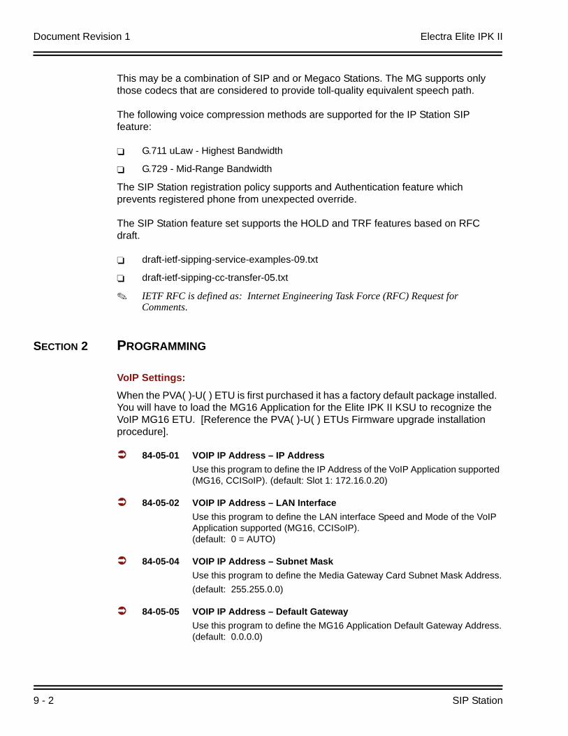
Document Revision 1 Electra Elite IPK II
9 - 2 SIP Station
This may be a combination of SIP and or Megaco Stations. The MG supports only those codecs that are considered to provide toll-quality equivalent speech path.
The following voice compression methods are supported for the IP Station SIP feature:
G.711 uLaw - Highest Bandwidth
G.729 - Mid-Range Bandwidth
The SIP Station registration policy supports and Authentication feature which prevents registered phone from unexpected override.
The SIP Station feature set supports the HOLD and TRF features based on RFC draft.
draft-ietf-sipping-service-examples-09.txt
draft-ietf-sipping-cc-transfer-05.txt
IETF RFC is defined as: Internet Engineering Task Force (RFC) Request for Comments.
SECTION 2 PROGRAMMING
VoIP Settings:When the PVA( )-U( ) ETU is first purchased it has a factory default package installed. You will have to load the MG16 Application for the Elite IPK II KSU to recognize the VoIP MG16 ETU. [Reference the PVA( )-U( ) ETUs Firmware upgrade installation procedure].
84-05-01 VOIP IP Address – IP AddressUse this program to define the IP Address of the VoIP Application supported (MG16, CCISoIP). (default: Slot 1: 172.16.0.20)
84-05-02 VOIP IP Address – LAN Interface Use this program to define the LAN interface Speed and Mode of the VoIP Application supported (MG16, CCISoIP). (default: 0 = AUTO)
84-05-04 VOIP IP Address – Subnet Mask Use this program to define the Media Gateway Card Subnet Mask Address.(default: 255.255.0.0)
84-05-05 VOIP IP Address – Default GatewayUse this program to define the MG16 Application Default Gateway Address.(default: 0.0.0.0)

Electra Elite IPK II Document Revision 1
Electra Elite IPK II VoIP Reference Manual 9 - 3
84-06-01 VoIP Info – RTP Port Number Use this program to define the Media Gateway Card starting RTP Port Number.(default: 10020)
84-06-02 VoIP Info – RTCP Port NumberUse this program to define the Media Gateway Card Starting RTCP Port Number . The RTCP Port Number has to be the (RTP port number + 1).(default: 10021)
84-06-04 VoIP Info – Fract Lost ThresholdUse this program to define the fractional lost threshold – this data will be sent to the IPK II CPU when the value exceeds the defined value.(default: 0)
84-06-05 VoIP Info – Packets Lost ThresholdUse this program to define the packet lost threshold - this data will be sent to the IPK II CPU when the value exceeds the defined value.(default: 0)
84-06-06 VoIP Info – Ext High Sequence Threshold Use this program to define the high sequence threshold - this data will be sent to the IPK II CPU when the value exceeds the defined value.(default: 0)
84-06-07 VoIP Info – Jitter ThresholdUse this program to define the Jitter Threshold - this data will be sent to the IPK II CPU when the value exceeds the defined value.(default: 0)
84-06-08 VoIP Info – Last LSR ThresholdUse this program to define the Last LSR Threshold - this data will be sent to the IPK II CPU when the value exceeds the defined value.(default: 0)
84-06-09 VoIP Info – Delay LSR ThresholdUse this program to define the Delay threshold – this data will be sent to the IPK II CPU when the value exceeds the defined value.(default: 0)

Document Revision 1 Electra Elite IPK II
9 - 4 SIP Station
VOIP ToS Setup:The Elite IPK II supports QoS Marking for SIP protocol.
84-10-01 Hardware Setup VOIP -ToS SetupUse this field to define your SIP QoS marking for ToS or Diffserve. 1=CPU, 2=MGC, 3=MEGACO, 5=RTP/RTCP, 6=SIP, 7=CCISoIP
SIP Peer-to-Peer
10-26-03 SIP Peer-to-PeerUse this program to enable or disable the Peer-to-Peer feature between SIP IP Stations.
SIP Stations to Megaco Stations do not support Peer-to-Peer function and will result in utilizing DSP Resources.Disabling this feature results in SIP IP Station-to-SIP IP Station calls utilizing DSP Resources.
IP Extension Numbering:
11-02-01 Extension NumberingUse this program to define the IP Phone extension number.
This designated extension will be used to register your IP Phone and will be programmed IP Phone programming. Refer to the Installation Instructions for Installation Instructions for Elite ITH-4D/8D/16D-2/3 Dterm IPK Terminals and the IP-R (IPK) Adapters.
SIP Extension Codec Information:
84-19-01 SIP Dterm IP CODEC Information Basic Setup – G.711 Audio FrameUse this program to define the G.71 audio Frame Size [1=10ms, 2=20ms, 3=30ms].(default: 3 = 30ms)
84-19-02 SIP Dterm IP CODEC Information Basic Setup – G.711 VAD ModeUse this program to enable or disable Voice Activity Detection for G.711.(default: 0:Disable)
84-19-03 SIP Dterm IP CODEC Information Basic Setup – G.711 TypeUse this program to define the G.711 Type – Mu-law is recommended when in USA.(default: 1: Mu-Law)
84-19-04 SIP Dterm IP CODEC Information Basic Setup – G.711 Jitter Buffer MinUse this program to define G.711 Jitter Buffer minimum accepted value – values are set in “ms”.(default: 30ms)
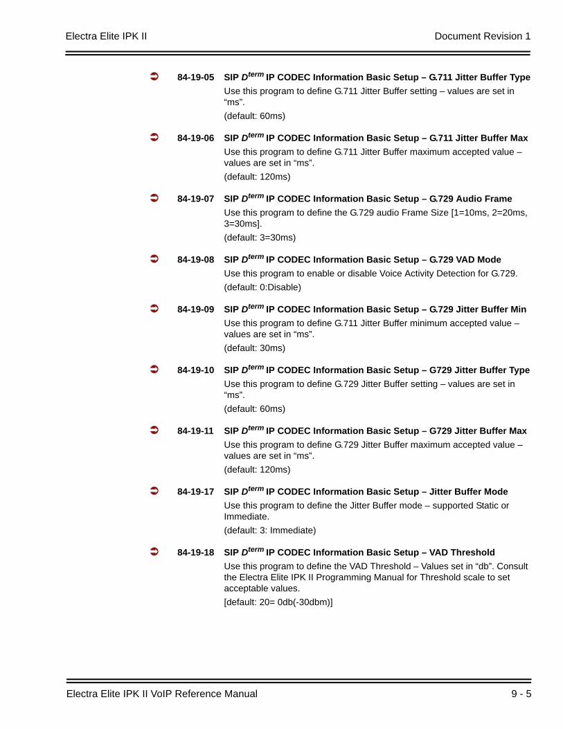
Electra Elite IPK II Document Revision 1
Electra Elite IPK II VoIP Reference Manual 9 - 5
84-19-05 SIP Dterm IP CODEC Information Basic Setup – G.711 Jitter Buffer TypeUse this program to define G.711 Jitter Buffer setting – values are set in “ms”.(default: 60ms)
84-19-06 SIP Dterm IP CODEC Information Basic Setup – G.711 Jitter Buffer MaxUse this program to define G.711 Jitter Buffer maximum accepted value – values are set in “ms”.(default: 120ms)
84-19-07 SIP Dterm IP CODEC Information Basic Setup – G.729 Audio FrameUse this program to define the G.729 audio Frame Size [1=10ms, 2=20ms, 3=30ms].(default: 3=30ms)
84-19-08 SIP Dterm IP CODEC Information Basic Setup – G.729 VAD ModeUse this program to enable or disable Voice Activity Detection for G.729.(default: 0:Disable)
84-19-09 SIP Dterm IP CODEC Information Basic Setup – G.729 Jitter Buffer MinUse this program to define G.711 Jitter Buffer minimum accepted value – values are set in “ms”.(default: 30ms)
84-19-10 SIP Dterm IP CODEC Information Basic Setup – G729 Jitter Buffer TypeUse this program to define G.729 Jitter Buffer setting – values are set in “ms”.(default: 60ms)
84-19-11 SIP Dterm IP CODEC Information Basic Setup – G729 Jitter Buffer MaxUse this program to define G.729 Jitter Buffer maximum accepted value – values are set in “ms”.(default: 120ms)
84-19-17 SIP Dterm IP CODEC Information Basic Setup – Jitter Buffer ModeUse this program to define the Jitter Buffer mode – supported Static or Immediate.(default: 3: Immediate)
84-19-18 SIP Dterm IP CODEC Information Basic Setup – VAD ThresholdUse this program to define the VAD Threshold – Values set in “db”. Consult the Electra Elite IPK II Programming Manual for Threshold scale to set acceptable values.[default: 20= 0db(-30dbm)]
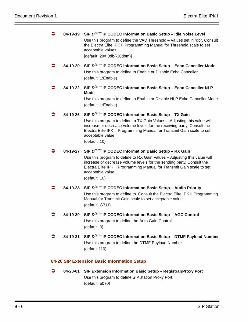
Document Revision 1 Electra Elite IPK II
9 - 6 SIP Station
84-19-19 SIP Dterm IP CODEC Information Basic Setup – Idle Noise LevelUse this program to define the VAD Threshold – Values set in “db”. Consult the Electra Elite IPK II Programming Manual for Threshold scale to set acceptable values.[default: 20= 0db(-30dbm)]
84-19-20 SIP Dterm IP CODEC Information Basic Setup – Echo Canceller ModeUse this program to define to Enable or Disable Echo Canceller.(default: 1:Enable)
84-19-22 SIP Dterm IP CODEC Information Basic Setup – Echo Canceller NLP ModeUse this program to define to Enable or Disable NLP Echo Canceller Mode.(default: 1:Enable)
84-19-26 SIP Dterm IP CODEC Information Basic Setup – TX GainUse this program to define to TX Gain Values – Adjusting this value will increase or decrease volume levels for the receiving party. Consult the Electra Elite IPK II Programming Manual for Transmit Gain scale to set acceptable value.(default: 10)
84-19-27 SIP Dterm IP CODEC Information Basic Setup – RX GainUse this program to define to RX Gain Values – Adjusting this value will increase or decrease volume levels for the sending party. Consult the Electra Elite IPK II Programming Manual for Transmit Gain scale to set acceptable value.(default: 10)
84-19-28 SIP Dterm IP CODEC Information Basic Setup – Audio PriorityUse this program to define to. Consult the Electra Elite IPK II Programming Manual for Transmit Gain scale to set acceptable value.(default: G711)
84-19-30 SIP Dterm IP CODEC Information Basic Setup – AGC ControlUse this program to define the Auto Gain Control.(default: 0)
84-19-31 SIP Dterm IP CODEC Information Basic Setup – DTMF Payload NumberUse this program to define the DTMF Payload Number.(default:110)
84-20 SIP Extension Basic Information Setup
84-20-01 SIP Extension Information Basic Setup – Registrar/Proxy PortUse this program to define SIP station Proxy Port.(default: 5070)
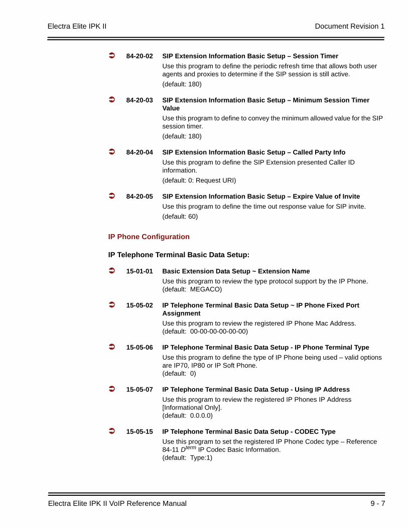
Electra Elite IPK II Document Revision 1
Electra Elite IPK II VoIP Reference Manual 9 - 7
84-20-02 SIP Extension Information Basic Setup – Session TimerUse this program to define the periodic refresh time that allows both user agents and proxies to determine if the SIP session is still active.(default: 180)
84-20-03 SIP Extension Information Basic Setup – Minimum Session Timer ValueUse this program to define to convey the minimum allowed value for the SIP session timer. (default: 180)
84-20-04 SIP Extension Information Basic Setup – Called Party InfoUse this program to define the SIP Extension presented Caller ID information. (default: 0: Request URI)
84-20-05 SIP Extension Information Basic Setup – Expire Value of InviteUse this program to define the time out response value for SIP invite.(default: 60)
IP Phone Configuration
IP Telephone Terminal Basic Data Setup:
15-01-01 Basic Extension Data Setup ~ Extension NameUse this program to review the type protocol support by the IP Phone. (default: MEGACO)
15-05-02 IP Telephone Terminal Basic Data Setup ~ IP Phone Fixed Port Assignment Use this program to review the registered IP Phone Mac Address.(default: 00-00-00-00-00-00)
15-05-06 IP Telephone Terminal Basic Data Setup - IP Phone Terminal TypeUse this program to define the type of IP Phone being used – valid options are IP70, IP80 or IP Soft Phone. (default: 0)
15-05-07 IP Telephone Terminal Basic Data Setup - Using IP AddressUse this program to review the registered IP Phones IP Address [Informational Only].(default: 0.0.0.0)
15-05-15 IP Telephone Terminal Basic Data Setup - CODEC TypeUse this program to set the registered IP Phone Codec type – Reference 84-11 Dterm IP Codec Basic Information. (default: Type:1)
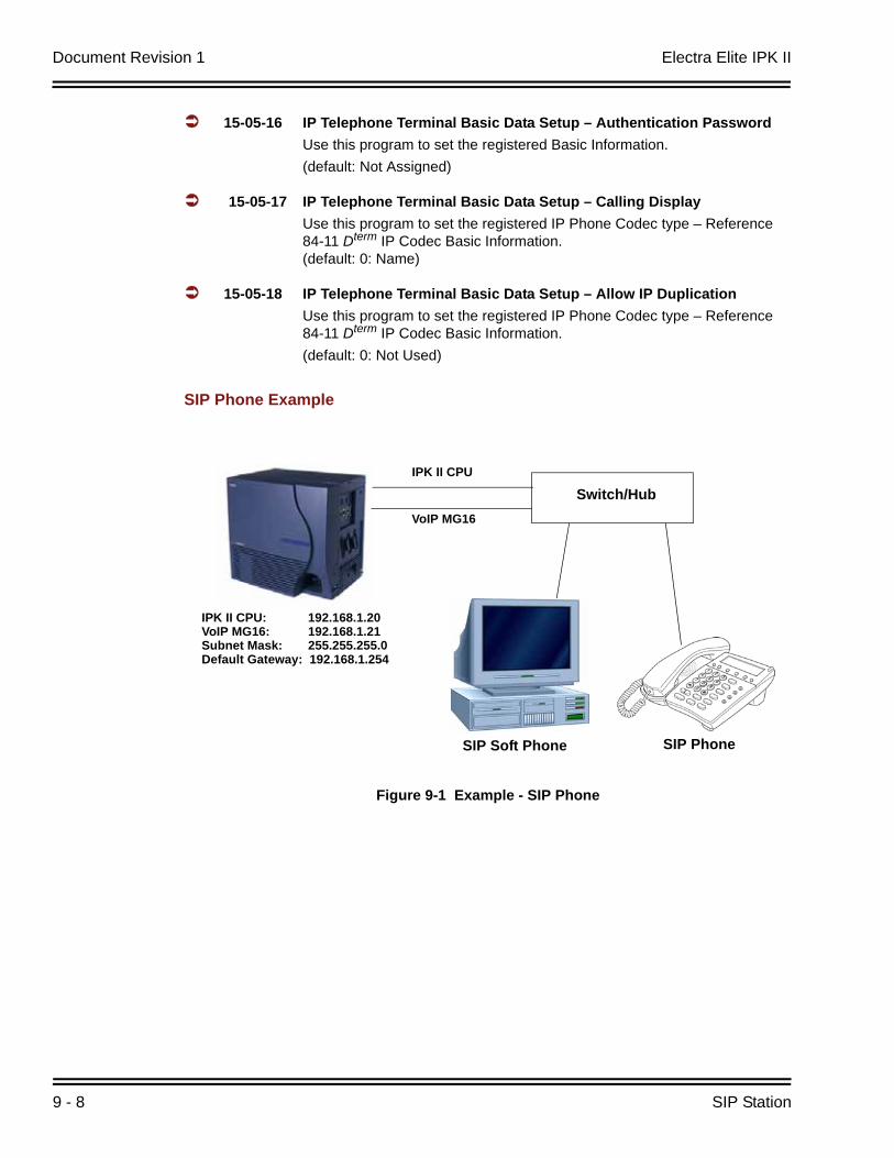
Document Revision 1 Electra Elite IPK II
9 - 8 SIP Station
15-05-16 IP Telephone Terminal Basic Data Setup – Authentication PasswordUse this program to set the registered Basic Information.(default: Not Assigned)
15-05-17 IP Telephone Terminal Basic Data Setup – Calling DisplayUse this program to set the registered IP Phone Codec type – Reference 84-11 Dterm IP Codec Basic Information.(default: 0: Name)
15-05-18 IP Telephone Terminal Basic Data Setup – Allow IP DuplicationUse this program to set the registered IP Phone Codec type – Reference 84-11 Dterm IP Codec Basic Information.(default: 0: Not Used)
SIP Phone Example
Figure 9-1 Example - SIP Phone
IPK II CPU: 192.168.1.20VoIP MG16: 192.168.1.21Subnet Mask: 255.255.255.0Default Gateway: 192.168.1.254
IPK II CPU
VoIP MG16
Switch/Hub
SIP Soft Phone SIP Phone
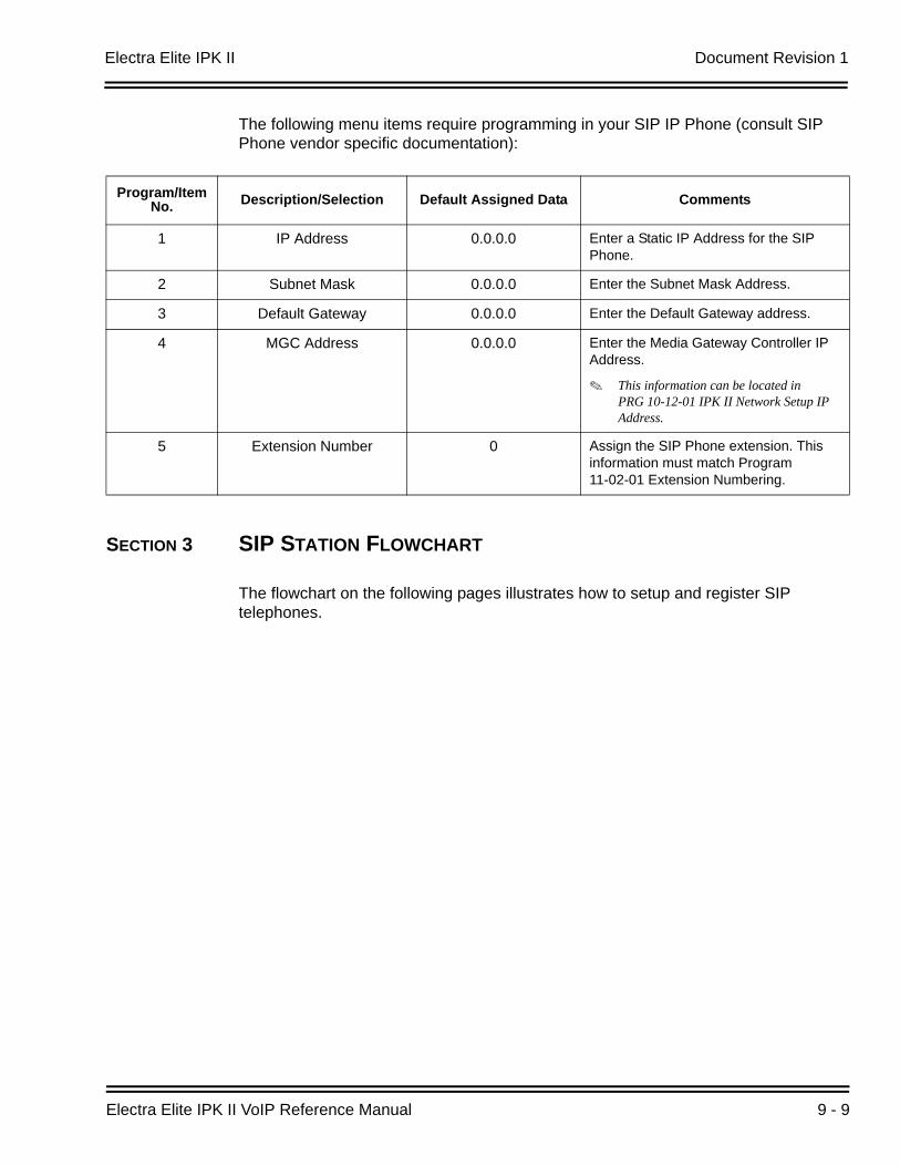
Electra Elite IPK II Document Revision 1
Electra Elite IPK II VoIP Reference Manual 9 - 9
The following menu items require programming in your SIP IP Phone (consult SIP Phone vendor specific documentation):
SECTION 3 SIP STATION FLOWCHART
The flowchart on the following pages illustrates how to setup and register SIP telephones.
Program/Item No. Description/Selection Default Assigned Data Comments
1 IP Address 0.0.0.0 Enter a Static IP Address for the SIP Phone.
2 Subnet Mask 0.0.0.0 Enter the Subnet Mask Address.
3 Default Gateway 0.0.0.0 Enter the Default Gateway address.
4 MGC Address 0.0.0.0 Enter the Media Gateway Controller IP Address.
This information can be located in PRG 10-12-01 IPK II Network Setup IP Address.
5 Extension Number 0 Assign the SIP Phone extension. This information must match Program 11-02-01 Extension Numbering.

Document Revision 1 Electra Elite IPK II
9 - 10 SIP Station
THIS PAGE INTENTIONALLY LEFT BLANK
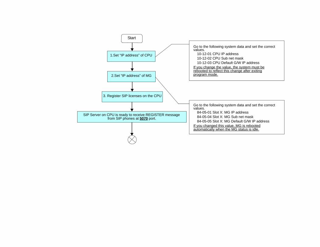
Go to the following system data and set the correct values.
10-12-01 CPU IP address10-12-02 CPU Sub net mask10-12-03 CPU Default G/W IP address
If you change the value, the system must berebooted to reflect this change after exitingprogram mode.
Go to the following system data and set the correct values.
84-05-01 Slot X: MG IP address84-05-04 Slot X: MG Sub net mask84-05-05 Slot X: MG Default G/W IP address
If you changed this value, MG is rebootedautomatically when the MG status is idle.
Start
1.Set “IP address” of CPU
2.Set “IP address” of MG
3. Register SIP licenses on the CPU
SIP Server on CPU is ready to receive REGISTER message from SIP phones at 5070 port.
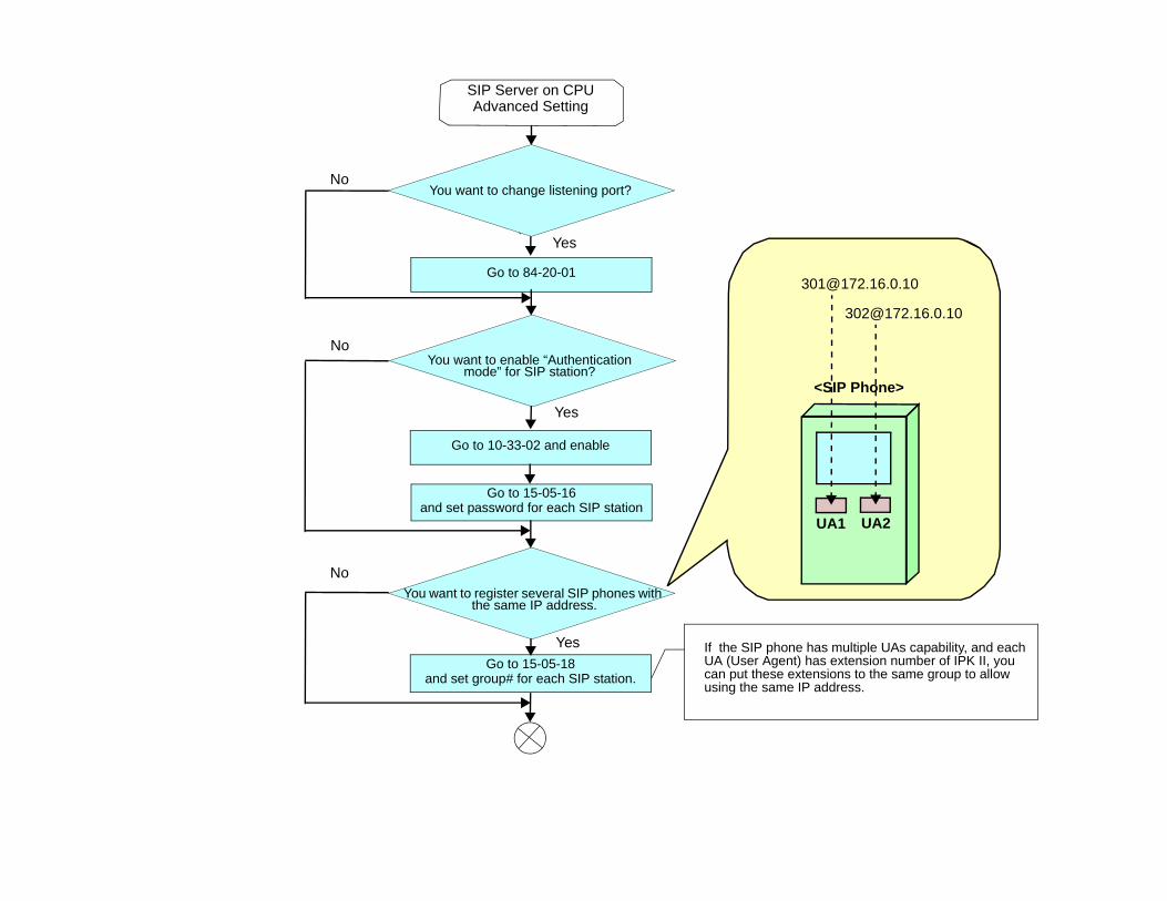
Yes
Yes
No
Go to 15-05-16 and set password for each SIP station
If the SIP phone has multiple UAs capability, and each UA (User Agent) has extension number of IPK II, you can put these extensions to the same group to allow using the same IP address.
Go to 15-05-18and set group# for each SIP station.
You want to register several SIP phones with the same IP address.
You want to enable “Authentication mode” for SIP station?
You want to change listening port?
Yes
Yes
No
No
Go to 84-20-01
Go to 10-33-02 and enable
SIP Server on CPU Advanced Setting
UA1 UA2
<SIP Phone>
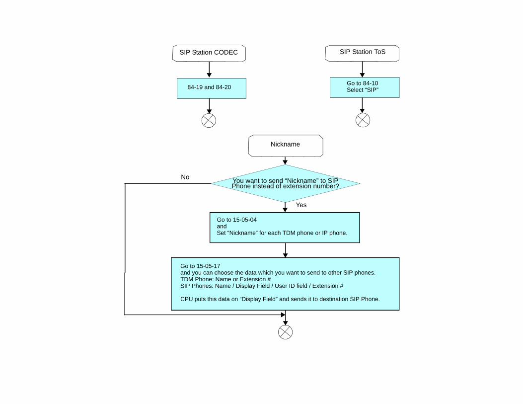
Nickname
You want to send “Nickname” to SIP Phone instead of extension number?
Yes
No
SIP Station CODEC
84-19 and 84-20
SIP Station ToS
Go to 84-10Select “SIP”
Go to 15-05-04 and Set “Nickname” for each TDM phone or IP phone.
Go to 15-05-17 and you can choose the data which you want to send to other SIP phones.TDM Phone: Name or Extension #SIP Phones: Name / Display Field / User ID field / Extension #
CPU puts this data on “Display Field” and sends it to destination SIP Phone.

Electra Elite IPK II VoIP Reference Manual 10 - 1
IP S
tation
(ME
GA
CO
) - MG
16
10IP Station (MEGACO) - MG16
SECTION 1 INTRODUCTION
The Media Gateway (MG16) is a IP Application loaded on the PVA( )-U( ) ETU. This is an optional interface package for the Electra Elite IPK II system that supports MEGACO IP stations.
An on-board 10/100 Base-T connector provides a WAN/LAN connection. Voice and signaling data to/from the IP stations are converted into IP Frames and transmitted through the Data Communication IP Network Intranet or Internet. Media Gateway 16 supports station-to-station direct RTP connections (peer-to-peer) for calls between IP telephones. Each Media Gateway 16 application can support up to 16 TDM Talk paths. Although, one Media Gateway Card can support 256 IP Megaco Stations, but will only provide 16 simultaneous talk paths across the TDM highway.
The MG Application contains a regular TCP/RTP/IP stack that can handle real-time media, supports industry standard MEGACO (H.248) communication on the WAN side, and interfaces with the Electra Elite IPK II.
For this feature, the Media Gateway 16 is installed and assigned as a VoIP MG16 ETU. Each Media Gateway 16 supports IP signaling for up to 16 Phones and reduces the maximum capacity of IP stations in the system by 16.
There can be only one Media Gateway Controller assigned in the Electra Elite IPK II. This determination will be made in KSU Programming [84-05-03] Master/Slave determination. The Media Gateway Controller interprets UDP signaling messages between the Elite IPK II Processor and IP Stations. Any additional MG16 ETUs added to the system will be known as Media Gateway cards. The media gateway card controls and interprets RTP messaging from the IP Phone to the Elite IPK II Processor.
If a non-System IP Phone (e.g., POT, System Phone), or trunk line is required, a DSP resource is needed. If while on a peer-to-peer call, DSP resources are not used and the MG16 port is not accessed, only Media Gateway Controller processing is used. If, while on a peer-to-peer call, a
Document Revision 1 Electra Elite IPK II
10 - 2 IP Station (MEGACO) - MG16
conference call is formed, the peer-to-peer connection is released and a new non peer-to-peer connection is created using the MG16 DSP resources - two ports will the used on the MG16 ETU. If the third party drops out of the conversation, the call reverts to a peer-to-peer call.
A maximum of 16 PVA( )-U( ) ETUs can be installed supporting the maximum of 256 IP stations (refer to Table 2-34 KSU Power-Based Calculator Chart on page 2-1018 in the Universal Slots feature).
The MG supports only those vocoders that are approved to provide toll-quality speech path. The following voice compression methods are supported for the IP Station (MEGACO) application:
G.711 uLaw - Highest Bandwidth
G.729 - Mid-Range Bandwidth
Each voice call requires at least the specifications listed in the following table. This includes all the overheads of VoIP communication, including signaling).
The MG16 contains a regular TCP/RTP/IP stack that can handle real time media. The MG16 ETU is an end-point on the IP network from the network administration perspective.
The MG16 uses MEGACO (H.248) Protocol to provide telephony services between remote stations through the IP Network. This is an IETF/ITU standards-based protocol.
Speech-connection audio quality depends greatly on the available bandwidth between the stations in the data network. Because Internet is an uncontrolled data network compared to an Intranet, using this application in Intranet WAN environment with known (or controlled and assured) Quality of Service (QoS) is highly recommended.
When connecting the voice calls across NAT/Firewall, consulting your network provider/administrator to specifically request service for VoIP or real-time media support on your networks is recommended.
CODEC Transmit Data Rate
Receive Data Rate
Time Between Packets
Packetization Delay
Default Jitter Buffer Delay
Theoretical Maximum
MOS
G711u Law 90 Kbps 90 Kbps 20 ms 1.5 ms 2 datagrams (40 ms)
4.4
G729 34 Kbps 34 Kbps 20 ms* 15.0 ms 2 datagrams (40 ms)
4.07
MOS = Mean Opinion Score When an IP Soft Phone is connected, set Time Between Packets to 100 ms.
Electra Elite IPK II Document Revision 1
Electra Elite IPK II VoIP Reference Manual 10 - 3
A static IP Address is required for each MG16 in the network.
The MG16 ETU and Elite IPK II CPU must be configured to communicate on the same network. This may require a second static IP Address for the IPK II CPU.
The MG16 supports station to station direct RTP connections (peer-to-peer) for calls between IP Phones that provide the following benefits:
Improved voice quality for calls between two IP Phones.
Improved bandwidth performance for voice between IP Phones.
Pad and echo canceller controls are built-in and are programmable via Elite IPK II KSU Programming.
The LAN/WAN connection is provided by a 10/100 Base-T Ethernet connector. This connector is a single 10/100 MPS Ethernet Connector. This port has Auto-Medium Dependent Interface Crossover (MDIX) to allow using either a straight-through Ethernet cable for connection to a PC or a crossover Ethernet cable.
The Ethernet Interface setting allows manual configuration of the Ethernet port from the Key System programming, and can be set to operate in the following port speed and duplex mode combinations: 10MB/Full Duplex, 10MB/HalfDuplex,100MB/Half Duplex, or 100MB/Full Duplex, Auto-Negotiate via Elite IPK II KSU Programming.
Registration Override is a feature for overriding the registration of an IP phone from various locations. You have to know the IP address of the IP phone and the extension number of the phone you want to Override.
In voice communication, particularly Internet telephony, the Mean Opinion Score (MOS) provides a numerical measure of the quality of human speech at the circuit destination. The scheme uses subjective tests (opinionated scores) that are mathematically averaged to obtain a quantitative indicator of the system performance. The maximum MOS is 5.0.
This interface supports via KSU configuration:
MEGACO (H.248) signaling Protocol
DTMF generation
RTP port number designation
ToS field QoS support
Tone generation
General Tone detection
G.711 and G.729a voice compression
10/100 Base-T LAN interface
Echo Canceller
Registration Override
Document Revision 1 Electra Elite IPK II
10 - 4 IP Station (MEGACO) - MG16
1.1 Feature Conditions
The following conditions apply when using IP Station (MEGACO) - MG1 6
Group listening is not supported by (MEGACO) IP stations.
Station Relocation is not supported by (MEGACO) IP stations or IPK Soft Phones.
Not all data networks are suitable to support Voice over Internet Protocol (VoIP). A good VoIP network solution requires low-latency, low jitter, and low packet loss. Accordingly, the network must be evaluated for these factors to determine whether or not it can provide toll-quality speech paths.
When 6- or 7-digit station numbers are used, this feature is not available.
Night Mode is indicated as N on an IPK Soft Phone.
Soft Phone is not supported when using Registration Override.
If call forwarding is set for an IP station, the system continues to follow the call forwarding, even if the station loses power or LAN connection.
If both Call Forward Busy and Call Forward No Answer are set, the system follows the Call Forward No Answer setting, even if the station loses power or LAN connection.
1.2 System Availability
1.2.1 Terminals
The following terminals can be used with the IP Station (MEGACO) - MG 16 feature:
ITH-16D-2/3 Multiline Terminal
ITH-8D-2/3 Multiline Terminal
Any IPK Multiline Terminal with IP-R (IPK) Unit installed.
IPK Soft Phone
1.2.2 Required Component(s)
The following components are required to provide the IP Station (MEGACO) MG 16 feature:
PVA(X)-U( ) ETU with MG16 Application Package 1.01 or Higher
PVA(X)-U( ) ETU with MG16 Application Package 1.5 or Higher to support Registration Override.
Electra Elite IPK II Document Revision 1
Electra Elite IPK II VoIP Reference Manual 10 - 5
AC-R UNIT (AC Adapter) [When in-line power is used, Power over Ethernet (POE), is not provided.]
IP Terminals - must be updated to Release 1.27 or higher to support this application.
IP Adapters - must be updated to Release 1.27 or higher to support this application.
1.3 Required Software
Software Version 1500 or higher provides the following:
Allows IP stations, which have call forwarding set, to continue forwarding calls, even if the station loses power or LAN connection.
The Registration Override feature gives users access to their IP telephone from any location by utilizing the override login function. Users have the flexibility of logging into their IP Station in the office as well as remotely at the home office.
The Center Download feature provides users with the ability to locally update the firmware on IP Terminals/Adapters. Each IP Terminal/Adapters can download the firmware through the use of a file server, thus reducing time and cost required to update each Terminal individually. The Center Download feature, when configured completely, allows the MG16 the ability to communicate with the IP Terminals via DRS listening port 161, gathering the IP Terminal’s Firmware information. The MG16 will then send an “Initial Setting Request” to the Elite IPK II CPU. The CPU will compare both the IP Phone firmware versions and the information programmed in system data to verify if the need for firmware is required on the IP Terminal. If a firmware upgrade is required, the CPU sends a download instruction. Refer to 2.3 Firmware Download Setup on page 10-7 in the System Data programming section and to 'To configure IP Terminal for Center Download' in the Operation section.
The MG16 web server will have a new HTTP page to display the network statistics based on values entered in PRG 84-06.
SECTION 2 PROGRAMMING
2.1 VoIP Settings
When the PVA( )-U( ) ETU is first purchased it has a factory default package installed. You will have to load the MG16 Application for the Elite IPK II KSU to recognize the VoIP MG16 ETU. [Reference the PVA( )-U( ) ETUs Firmware upgrade installation procedure].
Document Revision 1 Electra Elite IPK II
10 - 6 IP Station (MEGACO) - MG16
84-05-01 VOIP IP Address – IP AddressUse this program to define the IP Address of the VoIP Application supported (MG16, CCISoIP). (default: Slot 1: 172.16.0.20)
84-05-02 VOIP IP Address – LAN Interface Use this program to define the LAN interface Speed and Mode of the VoIP Application supported (MG16, CCISoIP). (default: 0 = AUTO)
84-05-03 VOIP IP Address – Master/SlaveUse this program to define the Media Gateway Controller for the MG16 application. (default: 1:MASTER)
The Elite IPK II system will support only 1 Media Gateway controller (determined by setting the MG16 Application to Master).
84-05-04 VOIP IP Address – Subnet Mask Use this program to define the Media Gateway Card Subnet Mask Address.(default: 255.255.0.0)
84-05-05 VOIP IP Address – Default GatewayUse this program to define the MG16 Application Default Gateway Address.(default: 0.0.0.0)
84-06-01 VoIP Info – RTP Port Number Use this program to define the Media Gateway Card starting RTP Port Number.(default: 10020)
84-06-02 VoIP Info – RTCP Port NumberUse this program to define the Media Gateway Card Starting RTCP Port Number . The RTCP Port Number has to be the (RTP port number + 1).(default: 10021)
84-06-04 VoIP Info – Fract Lost ThresholdUse this program to define the fractional lost threshold – this data will be sent to the IPK II CPU when the value exceeds the defined value.(default: 0)
84-06-05 VoIP Info – Packets Lost ThresholdUse this program to define the packet lost threshold - this data will be sent to the IPK II CPU when the value exceeds the defined value.(default: 0)
Electra Elite IPK II Document Revision 1
Electra Elite IPK II VoIP Reference Manual 10 - 7
84-06-07 VoIP Info – Jitter ThresholdUse this program to define the Jitter Threshold - this data will be sent to the IPK II CPU when the value exceeds the defined value.(default: 0)
84-06-09 VoIP Info – Delay LSR ThresholdUse this program to define the Delay threshold – this data will be sent to the IPK II CPU when the value exceeds the defined value.(default: 0)
2.2 VOIP ToS Setup
The Elite IPK II supports QoS Marking for the ToS and DiffServe on the following VoIP Applications: (MG16 and CCISoIP packages) 84-10-01 ToS Mode.
84-10-01 ToS Setup – ToS Mode Use this program to define the logic used for marking the ToS Field.(default: 0)
84-10-02 ToS Setup – Priority, IP Precedence Use this program to define the IP Precedence data bit.(default: 0)
Typically, only one of the bits 3 ~ 6 are set to 1 and the other three bits are set to 0. For example, to maximize route reliability, set 84-10-05 to 1, and leave 84-10-03, 84-10-04 and 84-10-06 at default (0).
84-10-07 ToS Setup – Priority (D.S.C.P. - Differential Services Code Point)Use this program to define the Diffserv – decimal value (valid values 0~63).(default: 0)
2.3 Firmware Download Setup
Use this data program to configure the required settings for Center Download file server access.
84-07-01 Firmware Download Setting – File Server ModeUse this program to select the mode type.0 = TFTP, 1 = FTP(default: 0)
84-07-02 Firmware Download Setting – File Server AddressUse this program to set the IP Address for the file server.(default: 0.0.0.0)
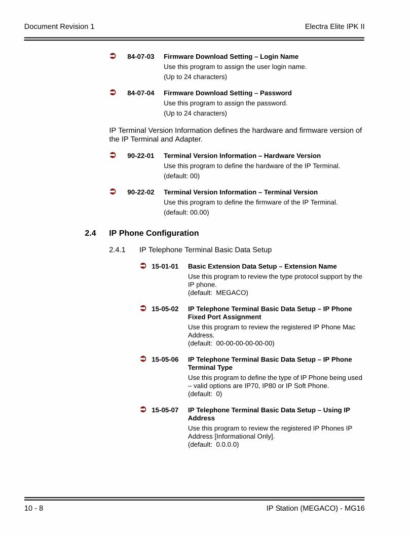
Document Revision 1 Electra Elite IPK II
10 - 8 IP Station (MEGACO) - MG16
84-07-03 Firmware Download Setting – Login NameUse this program to assign the user login name.(Up to 24 characters)
84-07-04 Firmware Download Setting – PasswordUse this program to assign the password.(Up to 24 characters)
IP Terminal Version Information defines the hardware and firmware version of the IP Terminal and Adapter.
90-22-01 Terminal Version Information – Hardware VersionUse this program to define the hardware of the IP Terminal.(default: 00)
90-22-02 Terminal Version Information – Terminal VersionUse this program to define the firmware of the IP Terminal.(default: 00.00)
2.4 IP Phone Configuration
2.4.1 IP Telephone Terminal Basic Data Setup
15-01-01 Basic Extension Data Setup – Extension NameUse this program to review the type protocol support by the IP phone. (default: MEGACO)
15-05-02 IP Telephone Terminal Basic Data Setup – IP Phone Fixed Port Assignment Use this program to review the registered IP Phone Mac Address.(default: 00-00-00-00-00-00)
15-05-06 IP Telephone Terminal Basic Data Setup – IP Phone Terminal TypeUse this program to define the type of IP Phone being used – valid options are IP70, IP80 or IP Soft Phone. (default: 0)
15-05-07 IP Telephone Terminal Basic Data Setup – Using IP AddressUse this program to review the registered IP Phones IP Address [Informational Only].(default: 0.0.0.0)
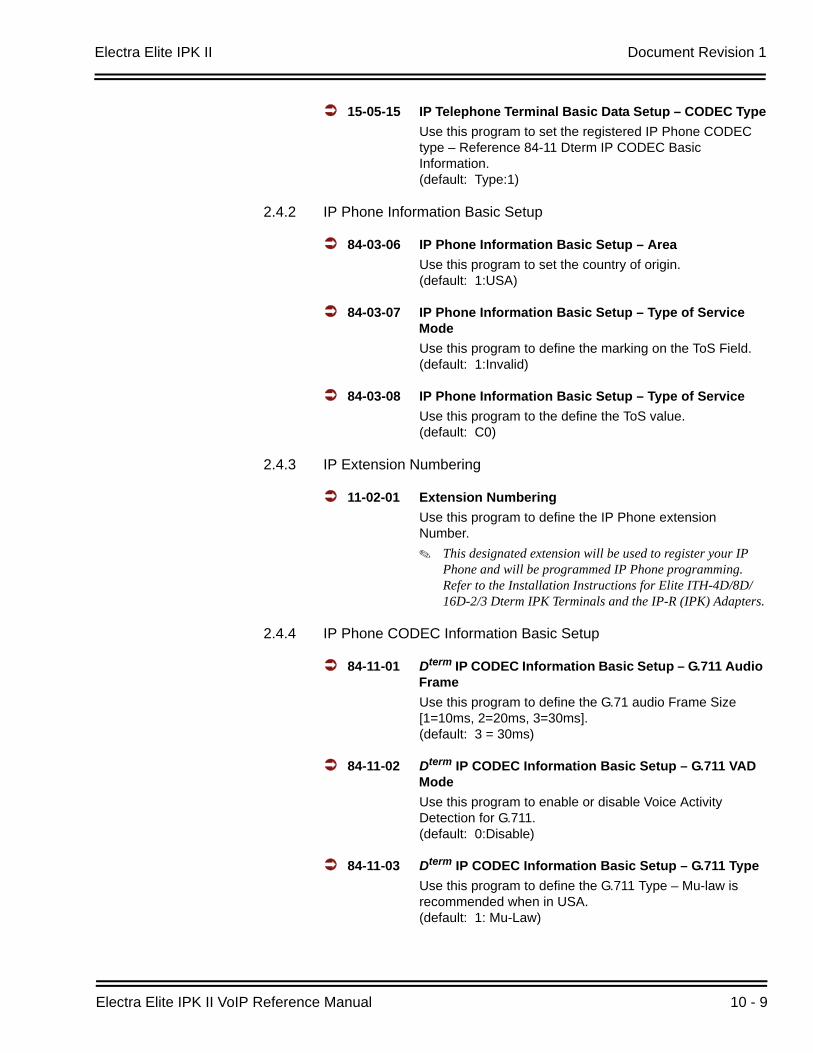
Electra Elite IPK II Document Revision 1
Electra Elite IPK II VoIP Reference Manual 10 - 9
15-05-15 IP Telephone Terminal Basic Data Setup – CODEC TypeUse this program to set the registered IP Phone CODEC type – Reference 84-11 Dterm IP CODEC Basic Information. (default: Type:1)
2.4.2 IP Phone Information Basic Setup
84-03-06 IP Phone Information Basic Setup – AreaUse this program to set the country of origin.(default: 1:USA)
84-03-07 IP Phone Information Basic Setup – Type of Service ModeUse this program to define the marking on the ToS Field. (default: 1:Invalid)
84-03-08 IP Phone Information Basic Setup – Type of ServiceUse this program to the define the ToS value. (default: C0)
2.4.3 IP Extension Numbering
11-02-01 Extension NumberingUse this program to define the IP Phone extension Number.
This designated extension will be used to register your IP Phone and will be programmed IP Phone programming. Refer to the Installation Instructions for Elite ITH-4D/8D/16D-2/3 Dterm IPK Terminals and the IP-R (IPK) Adapters.
2.4.4 IP Phone CODEC Information Basic Setup
84-11-01 Dterm IP CODEC Information Basic Setup – G.711 Audio FrameUse this program to define the G.71 audio Frame Size [1=10ms, 2=20ms, 3=30ms].(default: 3 = 30ms)
84-11-02 Dterm IP CODEC Information Basic Setup – G.711 VAD ModeUse this program to enable or disable Voice Activity Detection for G.711.(default: 0:Disable)
84-11-03 Dterm IP CODEC Information Basic Setup – G.711 TypeUse this program to define the G.711 Type – Mu-law is recommended when in USA.(default: 1: Mu-Law)
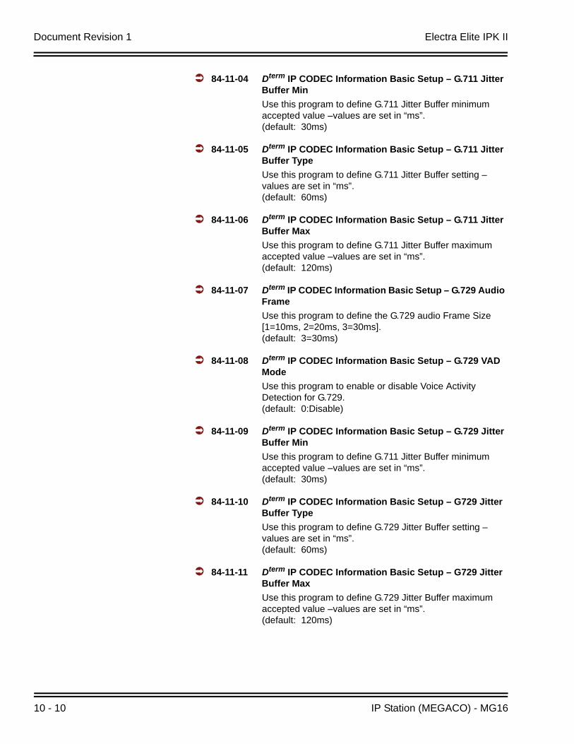
Document Revision 1 Electra Elite IPK II
10 - 10 IP Station (MEGACO) - MG16
84-11-04 Dterm IP CODEC Information Basic Setup – G.711 Jitter Buffer MinUse this program to define G.711 Jitter Buffer minimum accepted value –values are set in “ms”.(default: 30ms)
84-11-05 Dterm IP CODEC Information Basic Setup – G.711 Jitter Buffer TypeUse this program to define G.711 Jitter Buffer setting –values are set in “ms”. (default: 60ms)
84-11-06 Dterm IP CODEC Information Basic Setup – G.711 Jitter Buffer MaxUse this program to define G.711 Jitter Buffer maximum accepted value –values are set in “ms”.(default: 120ms)
84-11-07 Dterm IP CODEC Information Basic Setup – G.729 Audio FrameUse this program to define the G.729 audio Frame Size [1=10ms, 2=20ms, 3=30ms].(default: 3=30ms)
84-11-08 Dterm IP CODEC Information Basic Setup – G.729 VAD ModeUse this program to enable or disable Voice Activity Detection for G.729. (default: 0:Disable)
84-11-09 Dterm IP CODEC Information Basic Setup – G.729 Jitter Buffer MinUse this program to define G.711 Jitter Buffer minimum accepted value –values are set in “ms”.(default: 30ms)
84-11-10 Dterm IP CODEC Information Basic Setup – G729 Jitter Buffer TypeUse this program to define G.729 Jitter Buffer setting –values are set in “ms”.(default: 60ms)
84-11-11 Dterm IP CODEC Information Basic Setup – G729 Jitter Buffer MaxUse this program to define G.729 Jitter Buffer maximum accepted value –values are set in “ms”.(default: 120ms)
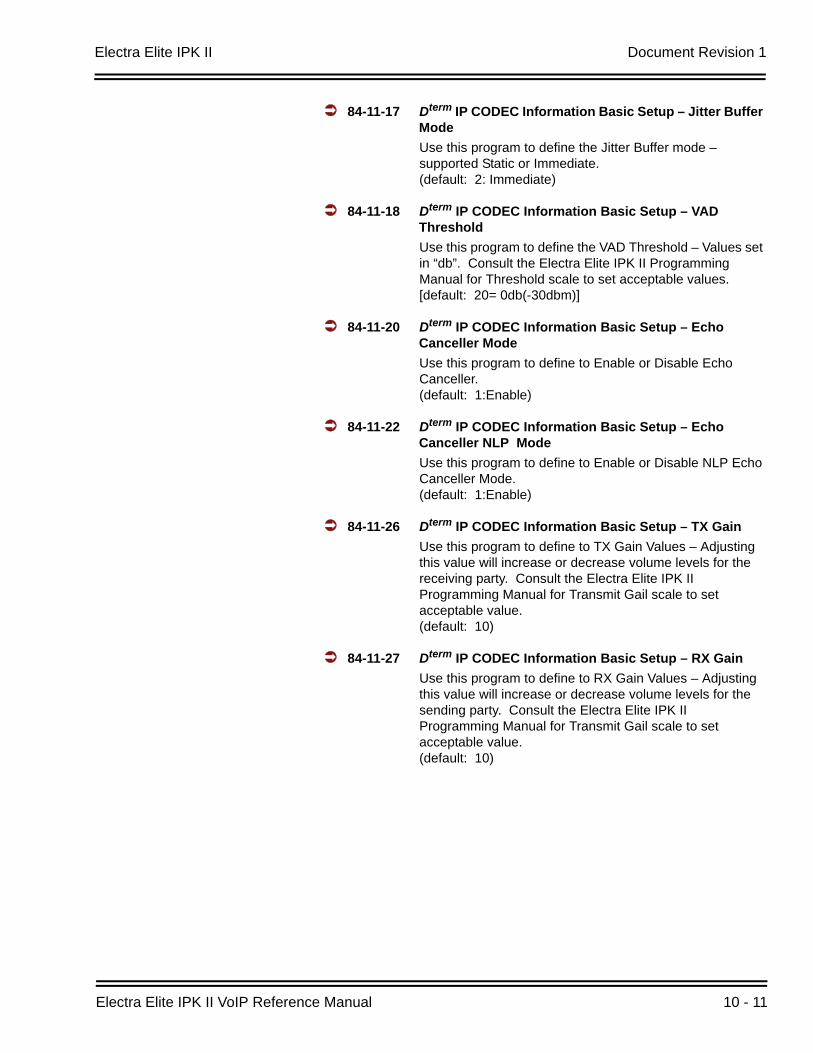
Electra Elite IPK II Document Revision 1
Electra Elite IPK II VoIP Reference Manual 10 - 11
84-11-17 Dterm IP CODEC Information Basic Setup – Jitter Buffer ModeUse this program to define the Jitter Buffer mode – supported Static or Immediate.(default: 2: Immediate)
84-11-18 Dterm IP CODEC Information Basic Setup – VAD ThresholdUse this program to define the VAD Threshold – Values set in “db”. Consult the Electra Elite IPK II Programming Manual for Threshold scale to set acceptable values. [default: 20= 0db(-30dbm)]
84-11-20 Dterm IP CODEC Information Basic Setup – Echo Canceller ModeUse this program to define to Enable or Disable Echo Canceller. (default: 1:Enable)
84-11-22 Dterm IP CODEC Information Basic Setup – Echo Canceller NLP ModeUse this program to define to Enable or Disable NLP Echo Canceller Mode. (default: 1:Enable)
84-11-26 Dterm IP CODEC Information Basic Setup – TX GainUse this program to define to TX Gain Values – Adjusting this value will increase or decrease volume levels for the receiving party. Consult the Electra Elite IPK II Programming Manual for Transmit Gail scale to set acceptable value.(default: 10)
84-11-27 Dterm IP CODEC Information Basic Setup – RX GainUse this program to define to RX Gain Values – Adjusting this value will increase or decrease volume levels for the sending party. Consult the Electra Elite IPK II Programming Manual for Transmit Gail scale to set acceptable value. (default: 10)
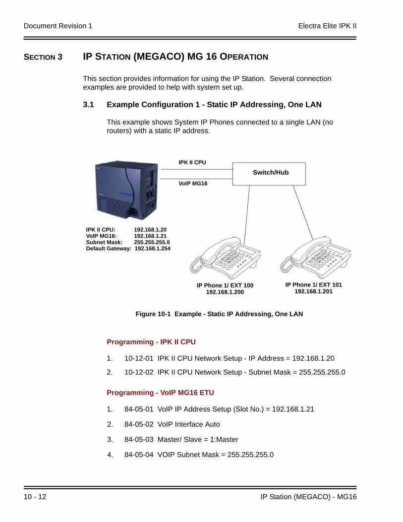
Document Revision 1 Electra Elite IPK II
10 - 12 IP Station (MEGACO) - MG16
SECTION 3 IP STATION (MEGACO) MG 16 OPERATION
This section provides information for using the IP Station. Several connection examples are provided to help with system set up.
3.1 Example Configuration 1 - Static IP Addressing, One LAN
This example shows System IP Phones connected to a single LAN (no routers) with a static IP address.
Programming - IPK II CPU
1. 10-12-01 IPK II CPU Network Setup - IP Address = 192.168.1.20
2. 10-12-02 IPK II CPU Network Setup - Subnet Mask = 255.255.255.0
Programming - VoIP MG16 ETU
1. 84-05-01 VoIP IP Address Setup (Slot No.) = 192.168.1.21
2. 84-05-02 VoIP Interface Auto
3. 84-05-03 Master/ Slave = 1:Master
4. 84-05-04 VOIP Subnet Mask = 255.255.255.0
Figure 10-1 Example - Static IP Addressing, One LAN
IPK II CPU: 192.168.1.20VoIP MG16: 192.168.1.21Subnet Mask: 255.255.255.0Default Gateway: 192.168.1.254
IPK II CPU
VoIP MG16
Switch/Hub
IP Phone 1/ EXT 100192.168.1.200
IP Phone 1/ EXT 101192.168.1.201
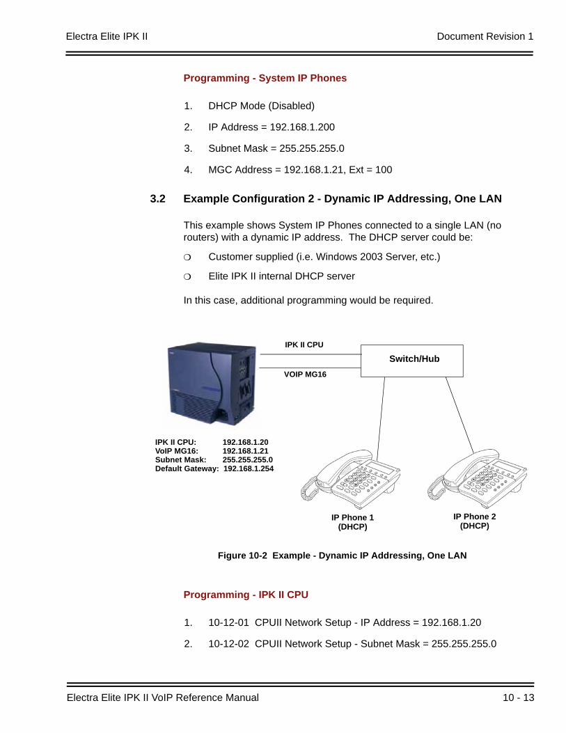
Electra Elite IPK II Document Revision 1
Electra Elite IPK II VoIP Reference Manual 10 - 13
Programming - System IP Phones
1. DHCP Mode (Disabled)
2. IP Address = 192.168.1.200
3. Subnet Mask = 255.255.255.0
4. MGC Address = 192.168.1.21, Ext = 100
3.2 Example Configuration 2 - Dynamic IP Addressing, One LAN
This example shows System IP Phones connected to a single LAN (no routers) with a dynamic IP address. The DHCP server could be:
Customer supplied (i.e. Windows 2003 Server, etc.)
Elite IPK II internal DHCP server
In this case, additional programming would be required.
Programming - IPK II CPU
1. 10-12-01 CPUII Network Setup - IP Address = 192.168.1.20
2. 10-12-02 CPUII Network Setup - Subnet Mask = 255.255.255.0
Figure 10-2 Example - Dynamic IP Addressing, One LAN
IPK II CPU
VOIP MG16
Switch/Hub
IP Phone 1(DHCP)
IP Phone 2(DHCP)
IPK II CPU: 192.168.1.20VoIP MG16: 192.168.1.21Subnet Mask: 255.255.255.0Default Gateway: 192.168.1.254

Document Revision 1 Electra Elite IPK II
10 - 14 IP Station (MEGACO) - MG16
Programming - System IP Phones
1. DHCP Mode - (Enabled)
3.3 Example Configuration 3 - Static IP Addressing, Routed LAN
This example shows System IP Phones connected to an Elite IPK II over a Wide Area Network (WAN) with static addressing. This is a typical scenario - a small branch office connecting to an Elite IPK II at the main office.
Programming - IPK II CPU
1. 10-12-01 CPUII Network Setup - IP Address = 192.168.1.20
2. 10-12-02 CPUII Network Setup - Subnet Mask = 255.255.255.0
3. 10-12-03 CPUII Network Setup - Default Gateway = 192.168.1.254
Figure 10-3 Example - Static IP Addressing, Routed WAN
IPK II CPU
VoIP MG16
Switch/Hub
IP Phone 1/101192.168.2.201
IPK II CPU: 192.168.1.20VoIP MG16: 192.168.1.21Subnet Mask: 255.255.255.0Default Gateway: 192.168.1.254
IP Phone 1/100192.168.2.200
Router192.168.1.254
WAN(Leased line, Frame Relay,
etc.)
Router192.168.2.254
Switch/Hub
Electra Elite IPK II Document Revision 1
Electra Elite IPK II VoIP Reference Manual 10 - 15
Programming - VoIP MG16
1. 84-05-01 VoIP MG16 IP Address Setup (Slot No.) = 192.168.1.21
Programming - System IP Phones
1. DHCP Mode (Disabled)
2. IP Address = 192.168.2.200
3. Subnet Mask = 255.255.255.0
4. Default Gateway = 192.168.2.254
CODEC Selection
IP Phones can use various CODECs (Coder/Decoder). A CODEC is a standard for converting an analog signal into a digital signal. This conversion process is handled by the DSP (Digital Signal Processors) on VoIP MG16 cards. Each CODEC has different voice quality and compression properties.
The correct choice of CODEC will be based on the amount of bandwidth available, the amount of calls required, and the voice quality required.
CODECs:
G.729. Low bandwidth requirement, and is used on most Wide Area Network links.
G.711. High bandwidth requirement - usually used on Local Area Networks.
The Elite IPK II IP Phones have a preferred CODEC, known as the “Audio Capability Priority”. This is the CODEC that will be used when calls are initiated. There are 5 “Types” (profiles) that can be created and assigned to IP Phones.
This allows for different CODECs to be used for different groups of IP Phones. In most cases, all IP Phones will belong to the same Type.
To create the CODEC Type (1~5), use the following programming:
IP Phone CODEC Information Basic Setup:
1. 84-11-01 G.711 Audio Frame (default: 3 = 30ms)
2. 84-11-02 G.711 VAD Mode (default: 0:Disable)
Document Revision 1 Electra Elite IPK II
10 - 16 IP Station (MEGACO) - MG16
3. 84-11-03 G.711 Type (default: 1: Mu-Law)
4. 84-11-04 G.711 Jitter Buffer Min (default: 30ms)
5. 84-11-05 G.711 Jitter Buffer Type – values are set in “ms” (default: 60ms)
6. 84-11-06 G.711 Jitter Buffer Max – values are set in “ms” (default: 120ms)
7. 84-11-07 G.729 Audio Frame [1=10ms, 2=20ms, 3=30ms] (default: 3=30ms)
8. 84-11-08 G.729 VAD Mode (default: 0:Disable)
9. 84-11-09 G.729 Jitter Buffer Min – values are set in “ms” (default: 30ms)
10. 84-11-10 G.729 Jitter Buffer Type – values are set in “ms” (default: 60ms)
11. 84-11-11 G7.29 Jitter Buffer Max – values are set in “ms” (default: 120ms)
12. 84-11-17 Jitter Buffer Mode – supported Static or Immediate (default: 2: Immediate)
13. 84-11-18 Voice Activity Detection Threshold – values set in “db” [default: 20= 0db(-30dbm)]
14. 84-11-20 Echo Canceller Mode (default: 1:Enable)
15. 84-11-22 Echo Canceller NLP Mode (default: 1:Enable)
16. 84-11-26 TX Gain (default: 14)
17. 84-11-27 RX Gain (default: 14)
84-11-28 : Dterm IP CODEC Information Settings - Audio Priority
For each Type, set the codec to use (default = G.711). By default, all IP Phones belong in Type 1.
To change the Type for an IP Phone:
15-05-15 : IP Phone Terminal Basic Data Setup - CODEC Type
For each IP Phone (extension number), select the Type to use (default = 1).
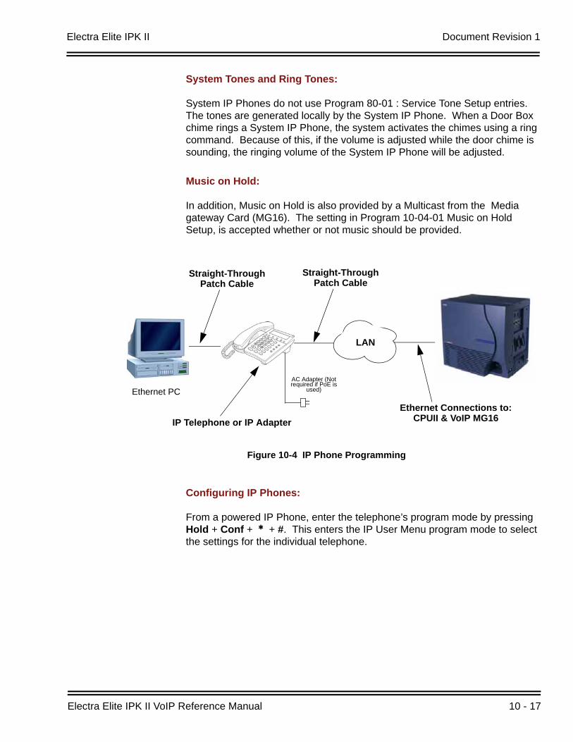
Electra Elite IPK II Document Revision 1
Electra Elite IPK II VoIP Reference Manual 10 - 17
System Tones and Ring Tones:
System IP Phones do not use Program 80-01 : Service Tone Setup entries. The tones are generated locally by the System IP Phone. When a Door Box chime rings a System IP Phone, the system activates the chimes using a ring command. Because of this, if the volume is adjusted while the door chime is sounding, the ringing volume of the System IP Phone will be adjusted.
Music on Hold:
In addition, Music on Hold is also provided by a Multicast from the Media gateway Card (MG16). The setting in Program 10-04-01 Music on Hold Setup, is accepted whether or not music should be provided.
Configuring IP Phones:
From a powered IP Phone, enter the telephone’s program mode by pressing Hold + Conf + + #. This enters the IP User Menu program mode to select the settings for the individual telephone.
Figure 10-4 IP Phone Programming
LAN
Ethernet PC
Straight-Through Patch Cable
Straight-Through Patch Cable
IP Telephone or IP Adapter
AC Adapter (Not required if PoE is
used)
Ethernet Connections to:CPUII & VoIP MG16

Document Revision 1 Electra Elite IPK II
10 - 18 IP Station (MEGACO) - MG16
The following menu items require programming in your IP Phone:
SECTION 4 FLOW CHART
The IP Megaco Station Flow Chart on the next page describes how to register and extension and how to program the Megaco station.
Program/Item No.
Description/Selection
Default Assigned
DataComments
1 Network Setting DHCP Disable
2 IP Address 0.0.0.0 Enter a Static IP Address for the IP Phone.
3 Subnet Mask 0.0.0.0 Enter the subnet Mask Address.
4 Default Gateway 0.0.0.0 Enter your Default Gateway address.
5 Speed & Duplex Auto
6 MGC Address 0.0.0.0 Enter the Media Gateway Controller IP Address.
When Multiple MG16 ETU are entered only the MG16 configured as "MASTER" in Data Program 84-05-03 will be set as MGC IP Address.
7 EXT 0 Assign the IP Phones extension. This information must match Program 11-02-01 Extension Numbering.
8 IP Address 0 Overriding an IP telephone must be done through phone programming.
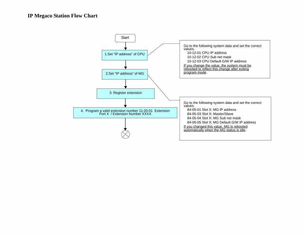
IP Megaco Station Flow Chart
Go to the following system data and set the correct values.
10-12-01 CPU IP address10-12-02 CPU Sub net mask10-12-03 CPU Default G/W IP address
If you change the value, the system must berebooted to reflect this change after exitingprogram mode.
Go to the following system data and set the correct values.
84-05-01 Slot X: MG IP address84-05-03 Slot X: Master/Slave84-05-04 Slot X: MG Sub net mask84-05-05 Slot X: MG Default G/W IP address
If you changed this value, MG is rebootedautomatically when the MG status is idle.
Start
1.Set “IP address” of CPU
2.Set “IP address” of MG
3. Register extension
4. Program a valid extension number 11-20-01 Extension Port X / Extension Number XXXX
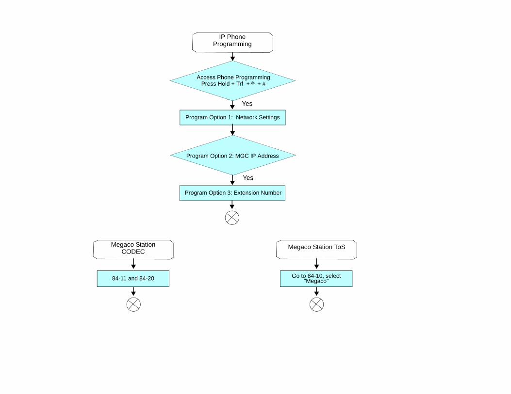
Yes
Yes
84-11 and 84-20
Program Option 2: MGC IP Address
Access Phone ProgrammingPress Hold + Trf + ∗ + #
Yes
Program Option 1: Network Settings
Program Option 3: Extension Number
IP Phone Programming
Megaco Station CODEC
Go to 84-10, select "Megaco"
Megaco Station ToS
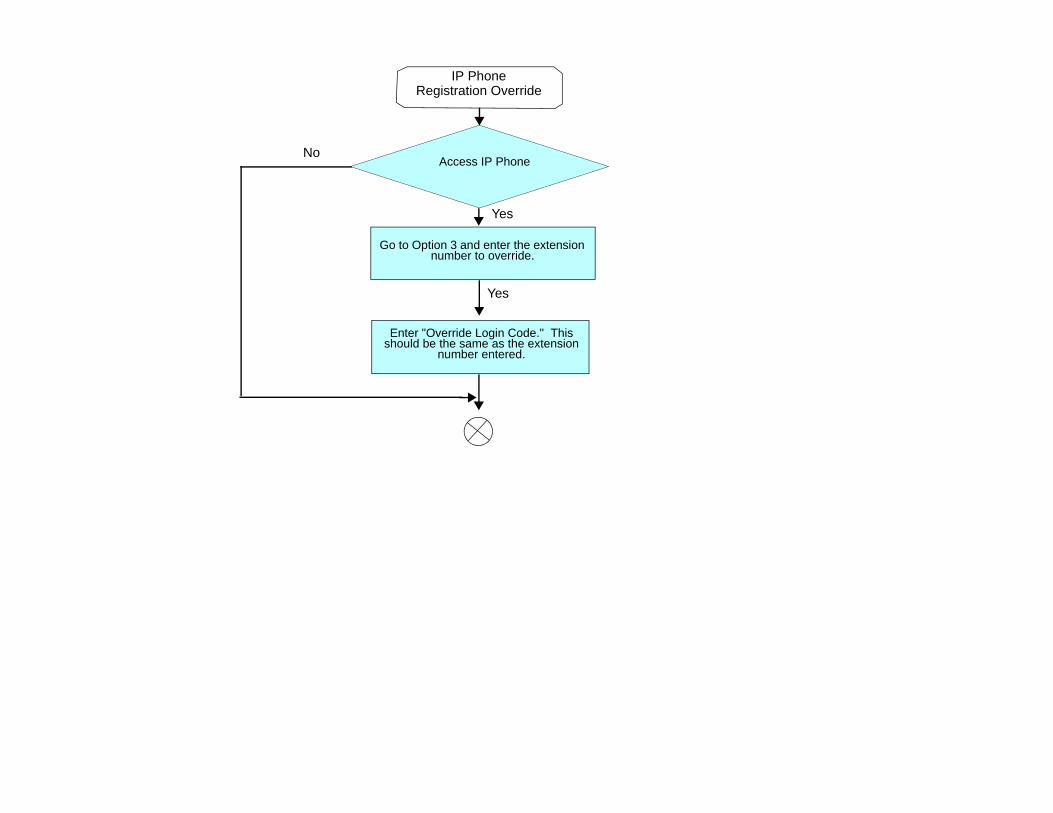
Access IP Phone
Yes
Go to Option 3 and enter the extension number to override.
Enter "Override Login Code." This should be the same as the extension
number entered.
IP Phone Registration Override
Yes
No

Electra Elite IPK II VoIP Reference Manual 11 - 1
PV
A C
om
bo
Ca
rd
11PVA Combo Card
SECTION 1 INTRODUCTION
The Electra Elite IPK II PVA Combo Card [PVA(X)-U( ) ETU} merges the MG16 Application and CCIS over IP Application into one package, providing users the flexibility to install and activate Megaco Station Clients (IP Phones), SIP Station Clients (SIP Phones), SIP Trunks and CCISoIP Networking. One PVA(X)-U( ) ETU provides all services with the PVA Combo Application Package.
The following IP Applications are supported on the PVA(X)-U( ) ETU Combo Card.
Megaco StationsThe Media Gateway (MG16) is an IP Application loaded on the PVA ( )-U( ) ETU that supports Megaco IP stations. This is an optional interface package for the Electra Elite IPK II system.
Media Gateway 16 supports station-to-station direct Real Time Protocol (RTP) connections (peer-to-peer) for calls between IP telephones. Each Media Gateway 16 application supports up to 16 Time Division Multiplexing (TDM) talk paths. Although, one Media Gateway Card can support 256 IP Megaco Stations, it only provides 16 simultaneous talk paths across the TDM highway.
Refer to Chapter 11 IP Station (MEGACO) - MG16 for details.
Only for the PVA Combo Card Application: has the ability to support 24 DSP resources which may be configured to the support MG16 application or CCISoIP Application.
SIP Stations and SIP Trunks
Each Media Gateway 16 application supports up to 16 TDM talk paths. This total can be shared among SIP Stations or SIP Trunks. Registered SIP Stations and/or SIP Trunks require a one-to-one relationship with the MG16 DSP Resource. This is a required component of SIP implementation in Electra Elite IPK II system.
Document Revision 1 Electra Elite IPK II
11 - 2 PVA Combo Card
The Electra Elite IPK II CPU contains a regular TCP/RTP/IP stack that can handle real-time media, supports industry standard SIP (RFC 3261) communication on the WAN side, and interfaces with the MG16 Application.
Only for the PVA Combo Card Application: has the ability to support 24 DSP resources which may be configured to the support MG16 application or CCISoIP Application.
Refer to Chapter 8 SIP Trunking and Chapter 9 SIP Station for detailed information.
CCISoIP Networking
The CCISoIP Application provides the benefits and additional feature compatibility of Key-Common Channel Interoffice Signaling (K-CCIS) between multiple systems including NEAX PBX systems connected together over a Data Communication IP Network (Intranet). Voice signals and common signaling data from/to the distant offices are converted into IP Packets and transmitted through the Data IP Network. When using the IP (K-CCIS) to NEAX (Point-to-Multipoint) feature, both voice and data communication lines are integrated into one network and communication costs can be reduced. This feature is available between Electra Elite IPK II systems and NEAX PBX systems
Refer to Chapter 4 IP Networking for detailed information.
Only the PVA Combo Card Application has the ability to support 24 DSP resources, which can be configured to the support MG16 application or CCISoIP application.
SECTION 2 SYSTEM REQUIREMENTS
2.1 Required Components
In addition to the PVA(X)-U( ) ETU with the PVA Combo Application Package version 1.00 or higher, the following are required:
IPK II CPU Version 2000 or higher software
SIP Client License
Megaco Client License
PVA(X)-U( ) ETU License
2.2 Stations, Trunks and Terminals
SIP Stations and Trunks
SIP stations and SIP trunks that are compliant with RFC 3261 are required.
Electra Elite IPK II Document Revision 1
Electra Elite IPK II VoIP Reference Manual 11 - 3
Terminals
The Megaco Station application supports the following terminals:
ITH-8D-2/3 and ITH-16D-2/3 Multiline Terminals
Any IPK Multiline Terminal with and IP-R (IPK) Unit installed
IP Soft Phone
When using IP terminals that use an AC-R Unit, note that Power over Ethernet (PoE) is not provided when in-line power is used.
IP terminals must be updated to terminal firmware release 1.27 or higher to support the application.
2.3 PVA Combo Card Service Conditions
The PVA Combo Card Application has the ability to support 24 DSP resources which may be configured to the support MG16 application or CCISoIP Application.
The PVA Combo Card CCISoIP Trunks and SIP Trunks Logical Port Numbers are determined by following:
SIP Trunks
PVA(X)-U( ) ETU License Registration
SIP Client License Registration
Elite IPK II Data Program 10-40-01 SIP Trunk Availability
Elite IPK II Data Program 10-40-02 Number of SIP Ports
CCISoIP Trunks
PVA(X)-U( ) ETU License Registration
Elite IPK II Data Program 10-40-03 CCISoIP Trunk Availability
Elite IPK II Data Program 10-40-04 Number of CCISoIP Ports
Additional Conditions
The maximum number of Logical Trunk Ports is 48 ports per PVA Combo Card package.
The PVA(X)-U( ) ETU with PVA Combo Card Application may configure DSP usage criteria with Elite IPK II “Data Program 10-19-01 DSP Resources” each VoIP ETU can flag individual DSP resources as:
IP Ext - IP Extensions (Includes Megaco Station or SIP Stations)
Document Revision 1 Electra Elite IPK II
11 - 4 PVA Combo Card
SIP Trk – SIP Trunks
CCIS – CCIS Networking
Common – Common usage for CCIS Networking, SIP Station, Megaco Stations, SIP Trunks.
ETU Configuration – The PVA Combo Card Application Package is identified as a “MG-CCIS” ETU Card Type.
When both CCIS and SIP Trunks are enabled, the CCIS Trunk Application will always register the first available logical port numbers.
The PVA Combo Card – VoIP ETU supports up to 200 CCIS Logical Trunks and 200 SIP Logical Trunk Port Numbers (read only).
IP Application DSP Resource configuration:
CCIS Trunks are defined as CCIS or Common
IP Megaco Stations are defined as IP Ext or Common
SIP Trunks are defined as SIP Trk or Common
SIP Station are defined as IP Ext or Common
When the PVA Combo Card is installed in the Electra Elite IPK II system, the system assigns the first available Logical Port Numbers for CCISoIP trunks and SIP trunks are allotted the next available logical port numbers.
If the Elite IPK II CPUII system does not have registered SIP licenses, the Logical SIP Trunk will not be assigned.
If the PVA Combo Card cannot establish the common highway, the maximum number of trunk ports is 16 ports for one package.
Changes in Data Program 10-40-03 and/or 10-40-04 requires the PVA(X)-U10 ETU to be reset for the new changes to become effective.
Changes in Data Program 10-19-01 requires a PVA(X)-U10 card reset for the changes to become effective
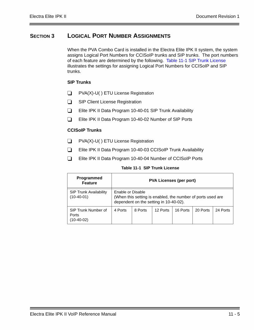
Electra Elite IPK II Document Revision 1
Electra Elite IPK II VoIP Reference Manual 11 - 5
SECTION 3 LOGICAL PORT NUMBER ASSIGNMENTS
When the PVA Combo Card is installed in the Electra Elite IPK II system, the system assigns Logical Port Numbers for CCISoIP trunks and SIP trunks. The port numbers of each feature are determined by the following. Table 11-1 SIP Trunk License illustrates the settings for assigning Logical Port Numbers for CCISoIP and SIP trunks.
SIP Trunks
PVA(X)-U( ) ETU License Registration
SIP Client License Registration
Elite IPK II Data Program 10-40-01 SIP Trunk Availability
Elite IPK II Data Program 10-40-02 Number of SIP Ports
CCISoIP Trunks
PVA(X)-U( ) ETU License Registration
Elite IPK II Data Program 10-40-03 CCISoIP Trunk Availability
Elite IPK II Data Program 10-40-04 Number of CCISoIP Ports
Table 11-1 SIP Trunk License
Programmed Feature PVA Licenses (per port)
SIP Trunk Availability (10-40-01)
Enable or Disable(When this setting is enabled, the number of ports used are dependent on the setting in 10-40-02).
SIP Trunk Number of Ports(10-40-02)
4 Ports 8 Ports 12 Ports 16 Ports 20 Ports 24 Ports
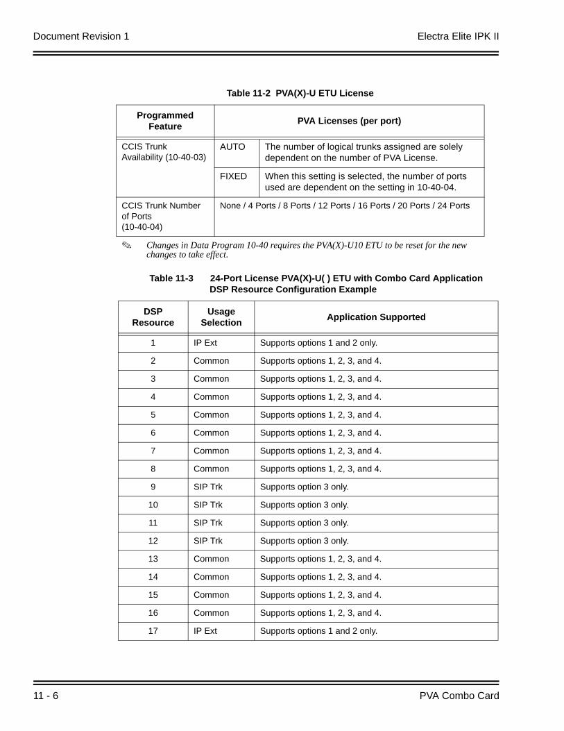
Document Revision 1 Electra Elite IPK II
11 - 6 PVA Combo Card
Table 11-2 PVA(X)-U ETU License
Programmed Feature PVA Licenses (per port)
CCIS Trunk Availability (10-40-03)
AUTO The number of logical trunks assigned are solely dependent on the number of PVA License.
FIXED When this setting is selected, the number of ports used are dependent on the setting in 10-40-04.
CCIS Trunk Number of Ports(10-40-04)
None / 4 Ports / 8 Ports / 12 Ports / 16 Ports / 20 Ports / 24 Ports
Changes in Data Program 10-40 requires the PVA(X)-U10 ETU to be reset for the new changes to take effect.
Table 11-3 24-Port License PVA(X)-U( ) ETU with Combo Card Application DSP Resource Configuration Example
DSP Resource
Usage Selection Application Supported
1 IP Ext Supports options 1 and 2 only.
2 Common Supports options 1, 2, 3, and 4.
3 Common Supports options 1, 2, 3, and 4.
4 Common Supports options 1, 2, 3, and 4.
5 Common Supports options 1, 2, 3, and 4.
6 Common Supports options 1, 2, 3, and 4.
7 Common Supports options 1, 2, 3, and 4.
8 Common Supports options 1, 2, 3, and 4.
9 SIP Trk Supports option 3 only.
10 SIP Trk Supports option 3 only.
11 SIP Trk Supports option 3 only.
12 SIP Trk Supports option 3 only.
13 Common Supports options 1, 2, 3, and 4.
14 Common Supports options 1, 2, 3, and 4.
15 Common Supports options 1, 2, 3, and 4.
16 Common Supports options 1, 2, 3, and 4.
17 IP Ext Supports options 1 and 2 only.
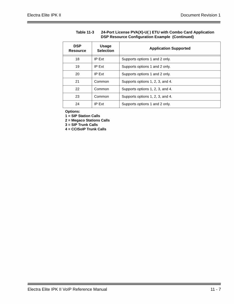
Electra Elite IPK II Document Revision 1
Electra Elite IPK II VoIP Reference Manual 11 - 7
18 IP Ext Supports options 1 and 2 only.
19 IP Ext Supports options 1 and 2 only.
20 IP Ext Supports options 1 and 2 only.
21 Common Supports options 1, 2, 3, and 4.
22 Common Supports options 1, 2, 3, and 4.
23 Common Supports options 1, 2, 3, and 4.
24 IP Ext Supports options 1 and 2 only.
Options:1 = SIP Station Calls2 = Megaco Stations Calls3 = SIP Trunk Calls4 = CCISoIP Trunk Calls
Table 11-3 24-Port License PVA(X)-U( ) ETU with Combo Card Application DSP Resource Configuration Example (Continued)
DSP Resource
Usage Selection Application Supported
Document Revision 1 Electra Elite IPK II
11 - 8 PVA Combo Card
SECTION 4 DIGITAL SIGNAL PROCESSING (DSP) RESOURCE HANDLING
The PVA(X)-U( ) ETU with PVA Combo Card Application distributes the use of DSP Resources using program 10-19-01 : VoIP DSP Resource Selection. This data program allows users to define the usage criteria for each DSP on the VOIP ETU. The following describes how DSP Resources are assigned for the IP Ext (IP Extension), SIP Trk (SIP Trunk), CCIS (CCIS Networking), Common (common usage for IP Ext, SIP Trk, and/or CCISoIP).
CCISoIP Application - CCIS TrunksThis feature can be defined as CCIS or Common utilizing any available DSP Resource.
MG16 Application - IP Megaco StationsThe feature can be defined as IP Ext or Common utilizing any available DSP Resource.
MG16 Application - SIP TrunkThe feature can be defined as SIP Trk or Common utilizing any available DSP Resource.
MG16 Application - SIP StationThe feature can be defined as IP Ext or Common utilizing any available DSP Resource.
SECTION 5 PROGRAMMING
5.1 VoIP Settings
Use program 10-03-01 : ETU Setup - Logical Port Number to set up and confirm basic configuration data for each ETU. When changing a defined terminal type, first set the terminal type to 0 and then plug in the new device and let the system automatically define it. Note that is may be necessary to reset the ETU.
The VOIP ETU supports CCIS Trunk Logical and SIP Trunk Logical Ports 0~200 (read only) and SIP Trunk.
The PVA Combo Card VOIP ETU supports Megaco Stations and SIP Stations Ports maximum of 256.
The system must have an ETU installed to view/change the options for the ETU type.
When the PVA( )-U( ) ETU is first purchased, it has a factory default package installed. Before the Elite IPK II KSU can recognize the ETU, load the VoIP application. [Refer to the Installation Instructions for Loading Firmware Package for PVA(X)-U( )ETU.]
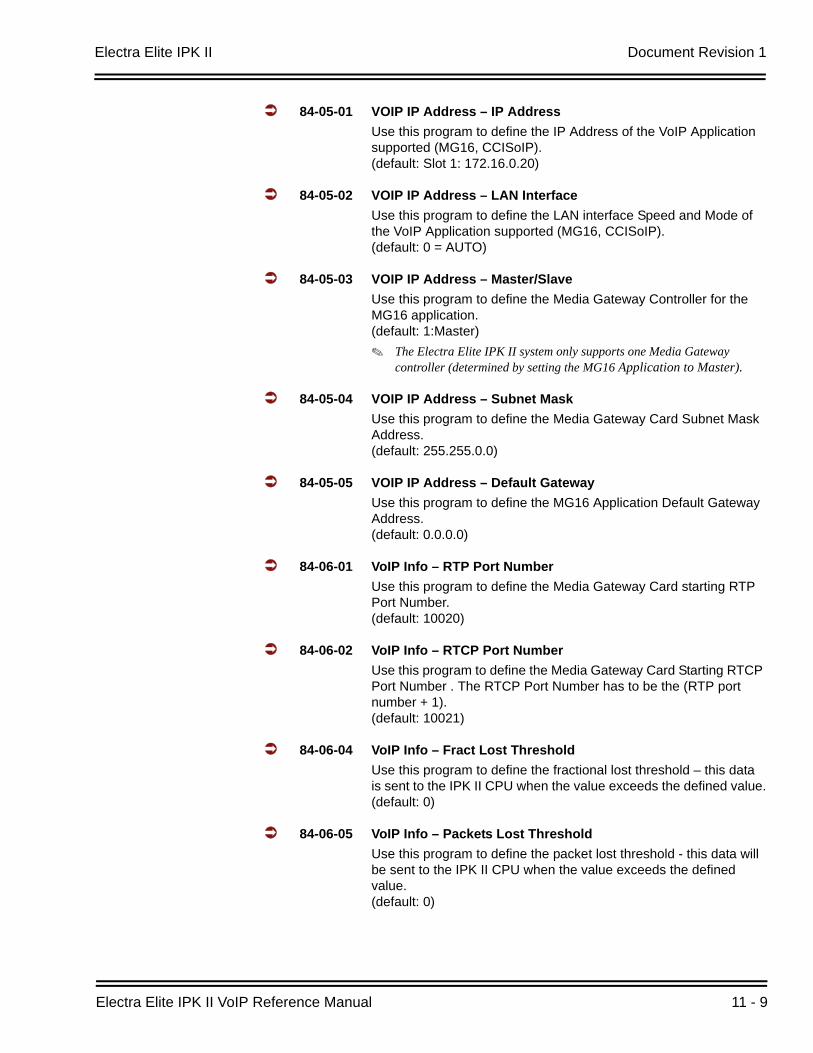
Electra Elite IPK II Document Revision 1
Electra Elite IPK II VoIP Reference Manual 11 - 9
84-05-01 VOIP IP Address – IP AddressUse this program to define the IP Address of the VoIP Application supported (MG16, CCISoIP).(default: Slot 1: 172.16.0.20)
84-05-02 VOIP IP Address – LAN InterfaceUse this program to define the LAN interface Speed and Mode of the VoIP Application supported (MG16, CCISoIP).(default: 0 = AUTO)
84-05-03 VOIP IP Address – Master/SlaveUse this program to define the Media Gateway Controller for the MG16 application.(default: 1:Master)
The Electra Elite IPK II system only supports one Media Gateway controller (determined by setting the MG16 Application to Master).
84-05-04 VOIP IP Address – Subnet MaskUse this program to define the Media Gateway Card Subnet Mask Address.(default: 255.255.0.0)
84-05-05 VOIP IP Address – Default GatewayUse this program to define the MG16 Application Default Gateway Address.(default: 0.0.0.0)
84-06-01 VoIP Info – RTP Port NumberUse this program to define the Media Gateway Card starting RTP Port Number.(default: 10020)
84-06-02 VoIP Info – RTCP Port NumberUse this program to define the Media Gateway Card Starting RTCP Port Number . The RTCP Port Number has to be the (RTP port number + 1).(default: 10021)
84-06-04 VoIP Info – Fract Lost ThresholdUse this program to define the fractional lost threshold – this data is sent to the IPK II CPU when the value exceeds the defined value.(default: 0)
84-06-05 VoIP Info – Packets Lost ThresholdUse this program to define the packet lost threshold - this data will be sent to the IPK II CPU when the value exceeds the defined value.(default: 0)
Document Revision 1 Electra Elite IPK II
11 - 10 PVA Combo Card
84-06-07 VoIP Info – Jitter ThresholdUse this program to define the Jitter Threshold - this data will be sent to the IPK II CPU when the value exceeds the defined value.(default: 0)
84-06-09 VoIP Info – Delay LSR ThresholdUse this program to define the Delay threshold – this data will be sent to the IPK II CPU when the value exceeds the defined value.(default: 0)
5.2 VOIP ToS Setup
The Electra Elite IPK II supports QoS Marking for the ToS and DiffServe on the following VoIP Protocols: SIP, MG16 and CCISoIP.
84-10-01 ToS Setup – ToS ModeUse this program to define the logic used for marking the ToS Field.(default: 0)
84-10-02 ToS Setup – Priority, IP PrecedenceUse this program to define the IP Precedence data bit.(default: 0)
Typically, only one of the bits 3 ~ 6 are set to 1 and the other three bits are set to 0. For example, to maximize route reliability, set 84-10-05 to 1, and leave 84-10-03, 84-10-04 and 84-10-06 at default (0).
84-10-07 ToS Setup – Priority (D.S.C.P. - Differential Services Code Point)Use this program to define the Diffserv – decimal value (valid values 0~63).(default: 0)
5.3 VoIP Logical Trunk Assignment
Use the programs listed in this section to make the appropriate logical trunk assignments.
10-40-01 VOIP Trunk Availability – SIP TrunksUse this program enable or disable SIP Trunks. Supported options include, 0:Disable or 1:enable.(Default: 0: Disable)
10-40-02 VOIP Trunk Availability – Number of PortsUse this program to define the number of Logical SIP Trunks utilized by the VoIP ETU supported options 0:4 ports, 1:8 ports, 2:12 ports, 3:16 ports, 4:20 ports, 5:24 ports. (default: 0: 4 Ports)
Electra Elite IPK II Document Revision 1
Electra Elite IPK II VoIP Reference Manual 11 - 11
10-40-03 VOIP Trunk Availability – CCISoIP TrunksUse this program to define how the CCISoIP Logical Trunk Number is assigned. Supported options are – 0: Auto, 1: Fixed. (default: 0: Auto)
To disable the CCISoIP Trunk Option Select Data Program 10-40-03 0: Fixed and 10-40-04 0:None.
Auto – Auto selection will define CCISoIP logical trunk numbers in accordance with the number of licensed ports on PVA(X)-U( ) ETU.Fixed – Fixed selection is determined by number of ports selected in program 10-40-04.
10-40-04 VOIP Trunk Availability – Number of portsUse this program to define the number of Logical CCISoIP Trunks utilized by the VoIP ETU supported options 0:None, 1:4 ports, 2:8 ports, 3:12 ports, 4:16 ports, 5:20 ports, 6: 24 ports. (default: 1:4 Ports)
5.4 VoIP DSP Resource Selection
Use the program listed in this section to define DSP Resource utilization.
10-19-01 VoIP DSP Resource Selection Use this program to define the usage criteria for each DSP Resource on the VoIP ETU. Supported options are – 0: Common, 1: IP Ext, 2: SIP TRK, 3:CCISoIP (default: 0 : Common)

Document Revision 1 Electra Elite IPK II
11 - 12 PVA Combo Card
THIS PAGE INTENTIONALLY LEFT BLANK
Electra Elite IPK II VoIP Reference Manual 12 - 1
Glo
ssary
12Glossary
Table 12-1 Glossary of Commonly used Abbreviations and Terms lists abbreviations and definitions for terms used throughout this document.
Table 12-1 Glossary of Commonly used Abbreviations and Terms
Term Definition
CCIS See Common-Channel Interoffice Signaling.
Common-Channel Interoffice Signaling
In multichannel switched networks, Common-Channel Interoffice Signaling, is a method of transmitting all signaling information for a group of trunks by encoding it and transmitting it over a separate channel using time-division digital techniques.
DHCP See Dynamic Host Configuration Protocol.
Digital Signal Processing Digital Signal Processing (DSP) refers to various techniques for improving the accuracy and reliability of digital communications. The theory behind DSP is quite complex. Basically, DSP works by clarifying, or standardizing, the levels or states of a digital signal. A DSP circuit is able to differentiate between human-made signals, which are orderly, and noise, which is inherently chaotic.
DSP See Digital Signal Processing.
Dynamic Address The temporary IP address is called a dynamic IP address. Because there are not enough IP numbers to go around, many Internet service providers limit the number of static IP addresses they allocate, and economize on the remaining number of IP addresses they possess by temporarily assigning an IP address to a requesting Dynamic Host Configuration Protocol (DHCP) computer from a pool of IP addresses.
Dynamic Host Configuration Protocol
Dynamic Host Configuration Protocol (DHCP) is a protocol, which assigns a dynamic IP address (see Dynamic Address).
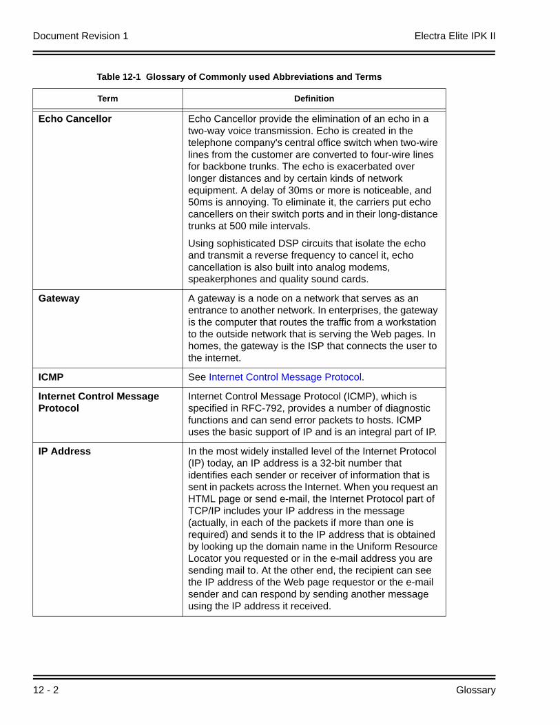
Document Revision 1 Electra Elite IPK II
12 - 2 Glossary
Echo Cancellor Echo Cancellor provide the elimination of an echo in a two-way voice transmission. Echo is created in the telephone company's central office switch when two-wire lines from the customer are converted to four-wire lines for backbone trunks. The echo is exacerbated over longer distances and by certain kinds of network equipment. A delay of 30ms or more is noticeable, and 50ms is annoying. To eliminate it, the carriers put echo cancellers on their switch ports and in their long-distance trunks at 500 mile intervals.
Using sophisticated DSP circuits that isolate the echo and transmit a reverse frequency to cancel it, echo cancellation is also built into analog modems, speakerphones and quality sound cards.
Gateway A gateway is a node on a network that serves as an entrance to another network. In enterprises, the gateway is the computer that routes the traffic from a workstation to the outside network that is serving the Web pages. In homes, the gateway is the ISP that connects the user to the internet.
ICMP See Internet Control Message Protocol.
Internet Control Message Protocol
Internet Control Message Protocol (ICMP), which is specified in RFC-792, provides a number of diagnostic functions and can send error packets to hosts. ICMP uses the basic support of IP and is an integral part of IP.
IP Address In the most widely installed level of the Internet Protocol (IP) today, an IP address is a 32-bit number that identifies each sender or receiver of information that is sent in packets across the Internet. When you request an HTML page or send e-mail, the Internet Protocol part of TCP/IP includes your IP address in the message (actually, in each of the packets if more than one is required) and sends it to the IP address that is obtained by looking up the domain name in the Uniform Resource Locator you requested or in the e-mail address you are sending mail to. At the other end, the recipient can see the IP address of the Web page requestor or the e-mail sender and can respond by sending another message using the IP address it received.
Table 12-1 Glossary of Commonly used Abbreviations and Terms
Term Definition
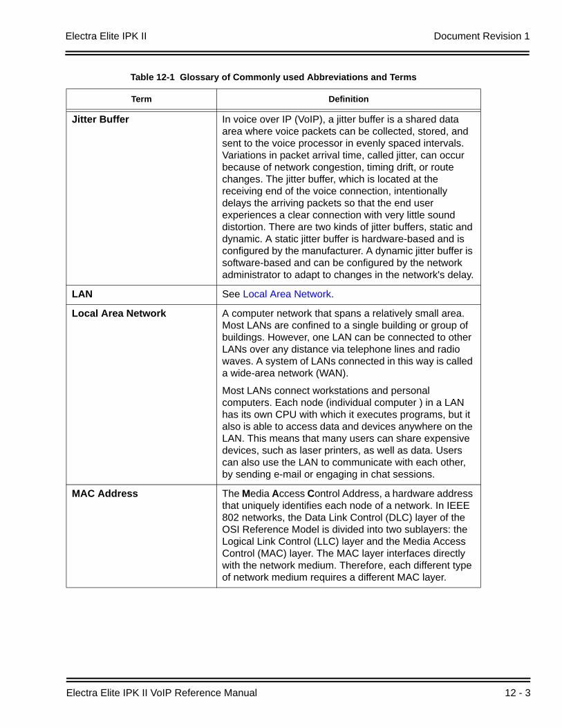
Electra Elite IPK II Document Revision 1
Electra Elite IPK II VoIP Reference Manual 12 - 3
Jitter Buffer In voice over IP (VoIP), a jitter buffer is a shared data area where voice packets can be collected, stored, and sent to the voice processor in evenly spaced intervals. Variations in packet arrival time, called jitter, can occur because of network congestion, timing drift, or route changes. The jitter buffer, which is located at the receiving end of the voice connection, intentionally delays the arriving packets so that the end user experiences a clear connection with very little sound distortion. There are two kinds of jitter buffers, static and dynamic. A static jitter buffer is hardware-based and is configured by the manufacturer. A dynamic jitter buffer is software-based and can be configured by the network administrator to adapt to changes in the network's delay.
LAN See Local Area Network.
Local Area Network A computer network that spans a relatively small area. Most LANs are confined to a single building or group of buildings. However, one LAN can be connected to other LANs over any distance via telephone lines and radio waves. A system of LANs connected in this way is called a wide-area network (WAN).
Most LANs connect workstations and personal computers. Each node (individual computer ) in a LAN has its own CPU with which it executes programs, but it also is able to access data and devices anywhere on the LAN. This means that many users can share expensive devices, such as laser printers, as well as data. Users can also use the LAN to communicate with each other, by sending e-mail or engaging in chat sessions.
MAC Address The Media Access Control Address, a hardware address that uniquely identifies each node of a network. In IEEE 802 networks, the Data Link Control (DLC) layer of the OSI Reference Model is divided into two sublayers: the Logical Link Control (LLC) layer and the Media Access Control (MAC) layer. The MAC layer interfaces directly with the network medium. Therefore, each different type of network medium requires a different MAC layer.
Table 12-1 Glossary of Commonly used Abbreviations and Terms
Term Definition
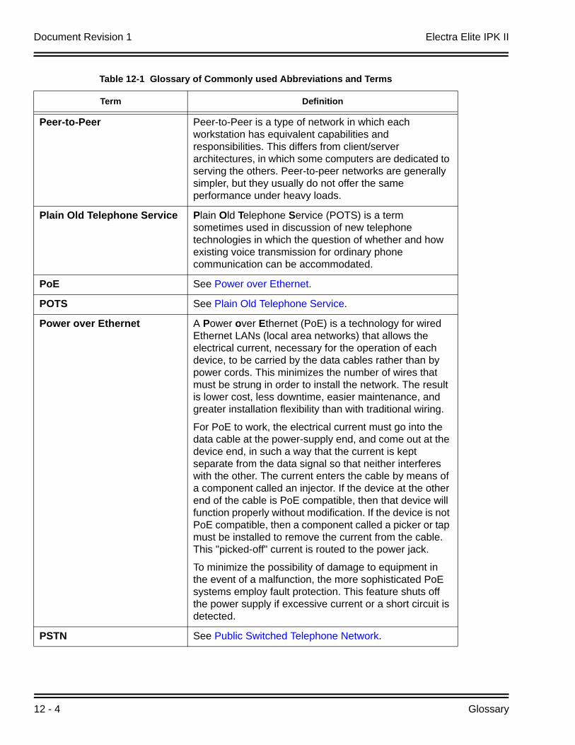
Document Revision 1 Electra Elite IPK II
12 - 4 Glossary
Peer-to-Peer Peer-to-Peer is a type of network in which each workstation has equivalent capabilities and responsibilities. This differs from client/server architectures, in which some computers are dedicated to serving the others. Peer-to-peer networks are generally simpler, but they usually do not offer the same performance under heavy loads.
Plain Old Telephone Service Plain Old Telephone Service (POTS) is a term sometimes used in discussion of new telephone technologies in which the question of whether and how existing voice transmission for ordinary phone communication can be accommodated.
PoE See Power over Ethernet.
POTS See Plain Old Telephone Service.
Power over Ethernet A Power over Ethernet (PoE) is a technology for wired Ethernet LANs (local area networks) that allows the electrical current, necessary for the operation of each device, to be carried by the data cables rather than by power cords. This minimizes the number of wires that must be strung in order to install the network. The result is lower cost, less downtime, easier maintenance, and greater installation flexibility than with traditional wiring.
For PoE to work, the electrical current must go into the data cable at the power-supply end, and come out at the device end, in such a way that the current is kept separate from the data signal so that neither interferes with the other. The current enters the cable by means of a component called an injector. If the device at the other end of the cable is PoE compatible, then that device will function properly without modification. If the device is not PoE compatible, then a component called a picker or tap must be installed to remove the current from the cable. This "picked-off" current is routed to the power jack.
To minimize the possibility of damage to equipment in the event of a malfunction, the more sophisticated PoE systems employ fault protection. This feature shuts off the power supply if excessive current or a short circuit is detected.
PSTN See Public Switched Telephone Network.
Table 12-1 Glossary of Commonly used Abbreviations and Terms
Term Definition
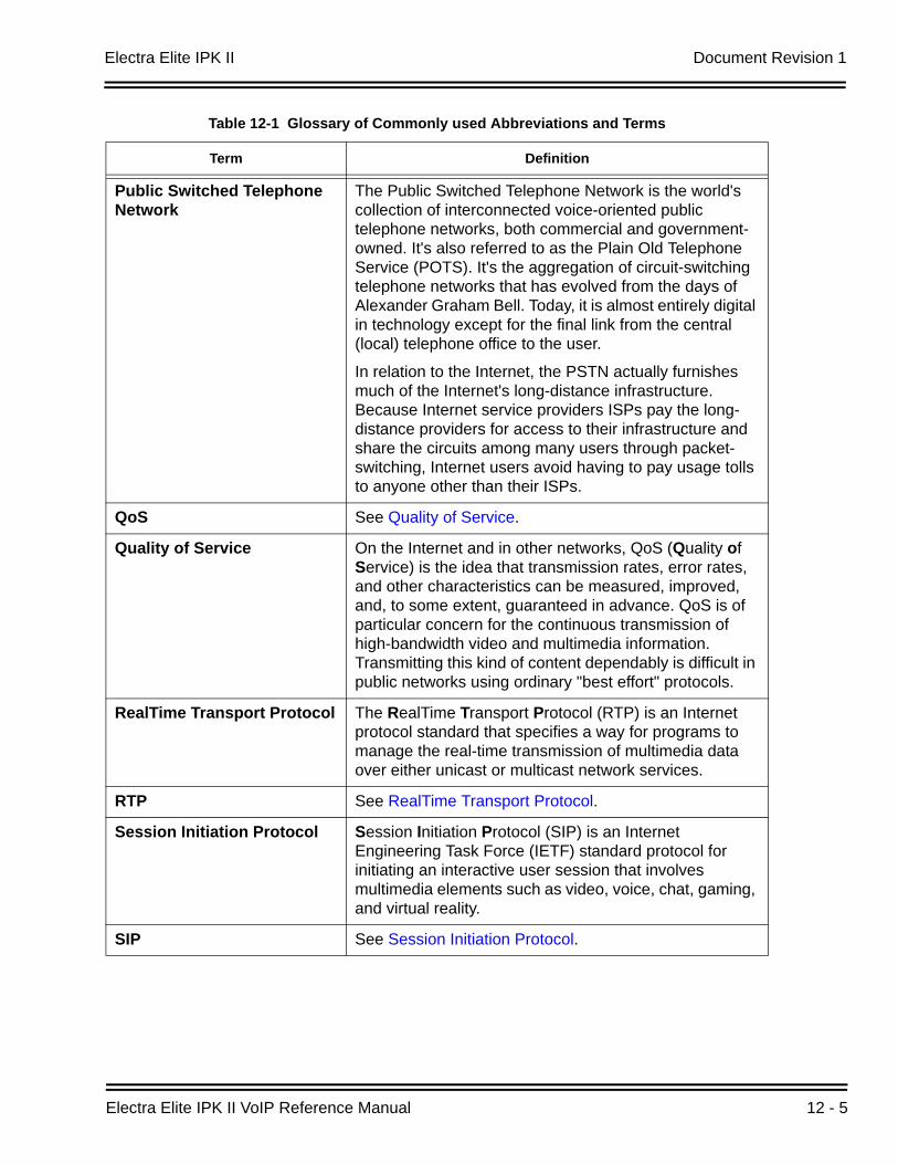
Electra Elite IPK II Document Revision 1
Electra Elite IPK II VoIP Reference Manual 12 - 5
Public Switched Telephone Network
The Public Switched Telephone Network is the world's collection of interconnected voice-oriented public telephone networks, both commercial and government-owned. It's also referred to as the Plain Old Telephone Service (POTS). It's the aggregation of circuit-switching telephone networks that has evolved from the days of Alexander Graham Bell. Today, it is almost entirely digital in technology except for the final link from the central (local) telephone office to the user.
In relation to the Internet, the PSTN actually furnishes much of the Internet's long-distance infrastructure. Because Internet service providers ISPs pay the long-distance providers for access to their infrastructure and share the circuits among many users through packet-switching, Internet users avoid having to pay usage tolls to anyone other than their ISPs.
QoS See Quality of Service.
Quality of Service On the Internet and in other networks, QoS (Quality of Service) is the idea that transmission rates, error rates, and other characteristics can be measured, improved, and, to some extent, guaranteed in advance. QoS is of particular concern for the continuous transmission of high-bandwidth video and multimedia information. Transmitting this kind of content dependably is difficult in public networks using ordinary "best effort" protocols.
RealTime Transport Protocol The RealTime Transport Protocol (RTP) is an Internet protocol standard that specifies a way for programs to manage the real-time transmission of multimedia data over either unicast or multicast network services.
RTP See RealTime Transport Protocol.
Session Initiation Protocol Session Initiation Protocol (SIP) is an Internet Engineering Task Force (IETF) standard protocol for initiating an interactive user session that involves multimedia elements such as video, voice, chat, gaming, and virtual reality.
SIP See Session Initiation Protocol.
Table 12-1 Glossary of Commonly used Abbreviations and Terms
Term Definition
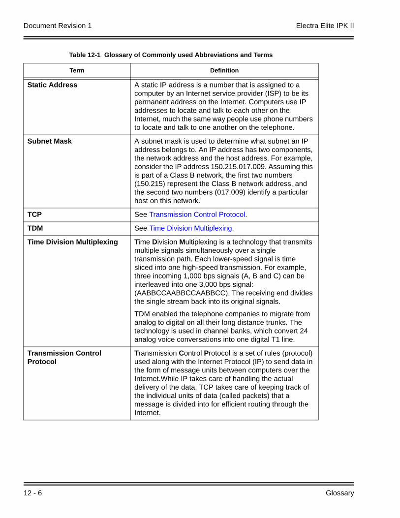
Document Revision 1 Electra Elite IPK II
12 - 6 Glossary
Static Address A static IP address is a number that is assigned to a computer by an Internet service provider (ISP) to be its permanent address on the Internet. Computers use IP addresses to locate and talk to each other on the Internet, much the same way people use phone numbers to locate and talk to one another on the telephone.
Subnet Mask A subnet mask is used to determine what subnet an IP address belongs to. An IP address has two components, the network address and the host address. For example, consider the IP address 150.215.017.009. Assuming this is part of a Class B network, the first two numbers (150.215) represent the Class B network address, and the second two numbers (017.009) identify a particular host on this network.
TCP See Transmission Control Protocol.
TDM See Time Division Multiplexing.
Time Division Multiplexing Time Division Multiplexing is a technology that transmits multiple signals simultaneously over a single transmission path. Each lower-speed signal is time sliced into one high-speed transmission. For example, three incoming 1,000 bps signals (A, B and C) can be interleaved into one 3,000 bps signal: (AABBCCAABBCCAABBCC). The receiving end divides the single stream back into its original signals.
TDM enabled the telephone companies to migrate from analog to digital on all their long distance trunks. The technology is used in channel banks, which convert 24 analog voice conversations into one digital T1 line.
Transmission Control Protocol
Transmission Control Protocol is a set of rules (protocol) used along with the Internet Protocol (IP) to send data in the form of message units between computers over the Internet.While IP takes care of handling the actual delivery of the data, TCP takes care of keeping track of the individual units of data (called packets) that a message is divided into for efficient routing through the Internet.
Table 12-1 Glossary of Commonly used Abbreviations and Terms
Term Definition
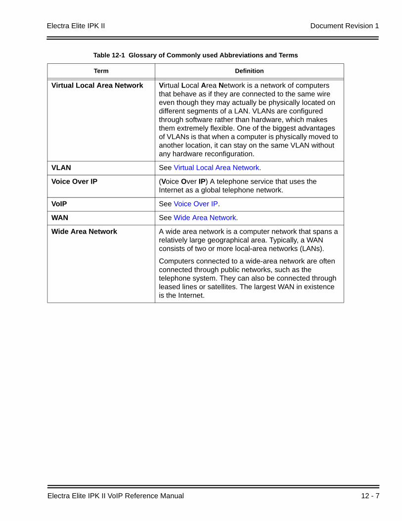
Electra Elite IPK II Document Revision 1
Electra Elite IPK II VoIP Reference Manual 12 - 7
Virtual Local Area Network Virtual Local Area Network is a network of computers that behave as if they are connected to the same wire even though they may actually be physically located on different segments of a LAN. VLANs are configured through software rather than hardware, which makes them extremely flexible. One of the biggest advantages of VLANs is that when a computer is physically moved to another location, it can stay on the same VLAN without any hardware reconfiguration.
VLAN See Virtual Local Area Network.
Voice Over IP (Voice Over IP) A telephone service that uses the Internet as a global telephone network.
VoIP See Voice Over IP.
WAN See Wide Area Network.
Wide Area Network A wide area network is a computer network that spans a relatively large geographical area. Typically, a WAN consists of two or more local-area networks (LANs).
Computers connected to a wide-area network are often connected through public networks, such as the telephone system. They can also be connected through leased lines or satellites. The largest WAN in existence is the Internet.
Table 12-1 Glossary of Commonly used Abbreviations and Terms
Term Definition

Document Revision 1 Electra Elite IPK II
12 - 8 Glossary
THIS PAGE INTENTIONALLY LEFT BLANK

VOIP REFERENCE MANUAL
NEC Unified Solutions, Inc.
Document Revision 1