elec 425 interference control in electronics -...
TRANSCRIPT

THE CITADEL, THE MILITARY COLLEGE OF SOUTH CAROLINA
171 Moultrie Street, Charleston, SC 29409
ELEC 425 – Interference Control in Electronics
Lecture 1(c)
Review of Decibels
& Decibel Arithmetic
Dr. Gregory J. Mazzaro
Fall 2017

2
Logarithms
logx
bN b N x where N = positive number (“linear value”)
b = the base of the logarithm
x = the exponent of the logarithm
-- a way to easily write/compare numbers
that are very large and/or very small,
simultaneously
-- an alternative to scientific notation
0.000001 6
0.001 3
1 0
1,000 3
1,000,000 6
N x
using b = 10
(“base-10”)…
Typical electric fields range from 1 mV/m
to 200 V/m 8 orders of magnitude.
The decibel scale compresses this data to a
narrower range of numbers.
3
Gain & Decibels
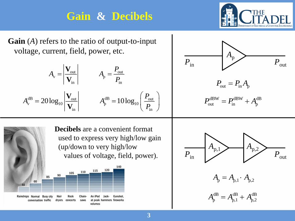
Gain (A) refers to the ratio of output-to-input
voltage, current, field, power, etc.
out outv p
in in
PA A
P
V
V
Ap,1 Ap,2PoutPin
p p,1 p,2A A A
dB dB dB
p p,1 p,2A A A
Decibels are a convenient format
used to express very high/low gain
(up/down to very high/low
values of voltage, field, power).
dB dBout outv 10 p 10
in in
20log 10logP
A AP
V
V
ApPoutPin
out in pP P A
dBW dBW dB
out in pP P A

4
Decibels: dB
dB
10 v v20 log A A
The decibel scale is a logarithmic
scale that uses base b = 10 . 10log N x
By convention,
gain in decibels is
v 1 2A
dB
v 6 dBA
Gai
n (
V/V
)G
ain
(d
B)
dB
v v
3
2
2
3
10 60
10 40
10 20
2 6
1 0
0.5 6
0.1 20
10 40
10 60
A A
dB
10 p p10 log A A
5
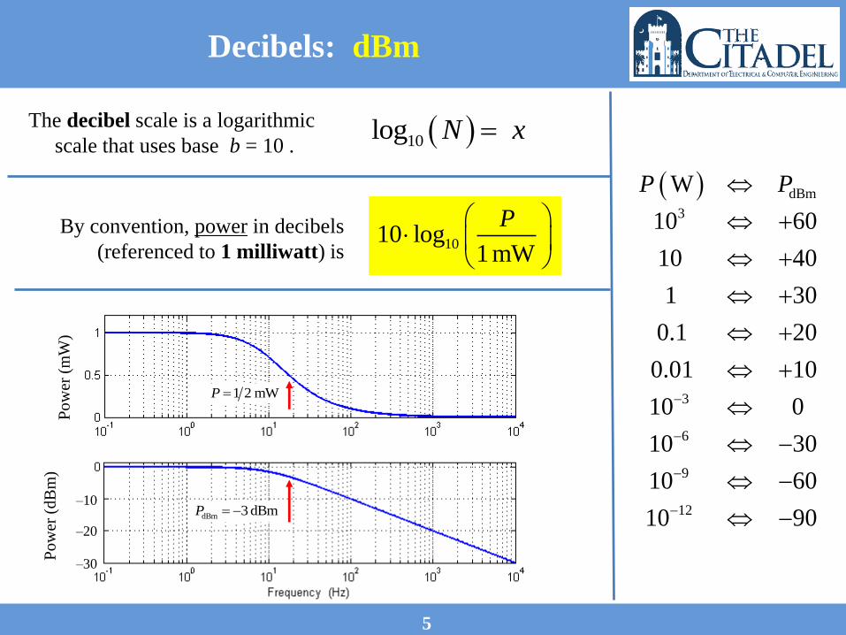
Decibels: dBm
1010 log1 mW
P
The decibel scale is a logarithmic
scale that uses base b = 10 . 10log N x
By convention, power in decibels
(referenced to 1 milliwatt) is
dBm
3
3
6
9
12
W
10 60
10 40
1 30
0.1 20
0.01 10
10 0
10 30
10 60
10 90
P P
1 2 mWP
dBm 3 dBmP
Po
wer
(m
W)
–10
–20
–30
Po
wer
(d
Bm
)

6
Decibels: dBmV/m
1020 log1μV m
E
The decibel scale is a logarithmic
scale that uses base b = 10 . 10log N x
By convention, electric field in decibels
(referenced to 1 microvolt per meter) is
1 2μV/mE
dB
μV/m 6 dBμV/mE
Fie
ld (m
V/m
)F
ield
(d
Bm
V/m
)
dB
μV/m μV/m
3
2
2
3
10 60
10 40
10 20
2 6
1 0
0.5 6
0.1 20
10 40
10 60
E E

7
Decibels: Circuits & Gain
outv
in
outi
in
outp
in
VA
V
IA
I
PA
P
2
inin
in
2
outout
L
VP
R
VP
R
dB outv 10
in
dB outi 10
in
dB outp 10
in
20log
20log
10log
VA
V
IA
I
PA
P
where Vin, Vout, Iin, Iout are
assumed to be RMS values.
Iin Iout
8
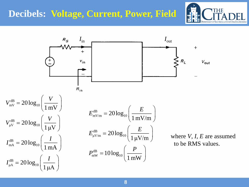
Decibels: Voltage, Current, Power, Field
where V, I, E are assumed
to be RMS values.
dB
mV 10
dB
μV 10
dB
mA 10
dB
μA 10
20log1 mV
20log1μV
20log1 mA
20log1μA
VV
VV
II
II
dB
mV/m 10
dB
μV/m 10
dB
mW 10
20log1 mV/m
20log1μV/m
10log1 mW
EE
EE
PP
Iin Iout

9
Examples: Decibel Conversions
Express the ratios of the following quantities in decibels:
Convert the following quantities to the specified decibel units:
(a) a power of 20 W
to a power of 1 mW
(b) a current of 2 mARMS
to a current of 0.5 ARMS
(c) 20 mV/m
to dBmV/m
(d) 300 mW
to dBm

THE CITADEL, THE MILITARY COLLEGE OF SOUTH CAROLINA
171 Moultrie Street, Charleston, SC 29409
ELEC 425 – Interference Control in Electronics
Lecture 1(d)
Cable Losses &
High-Frequency Signal Sources
Dr. Gregory J. Mazzaro
Fall 2017
12
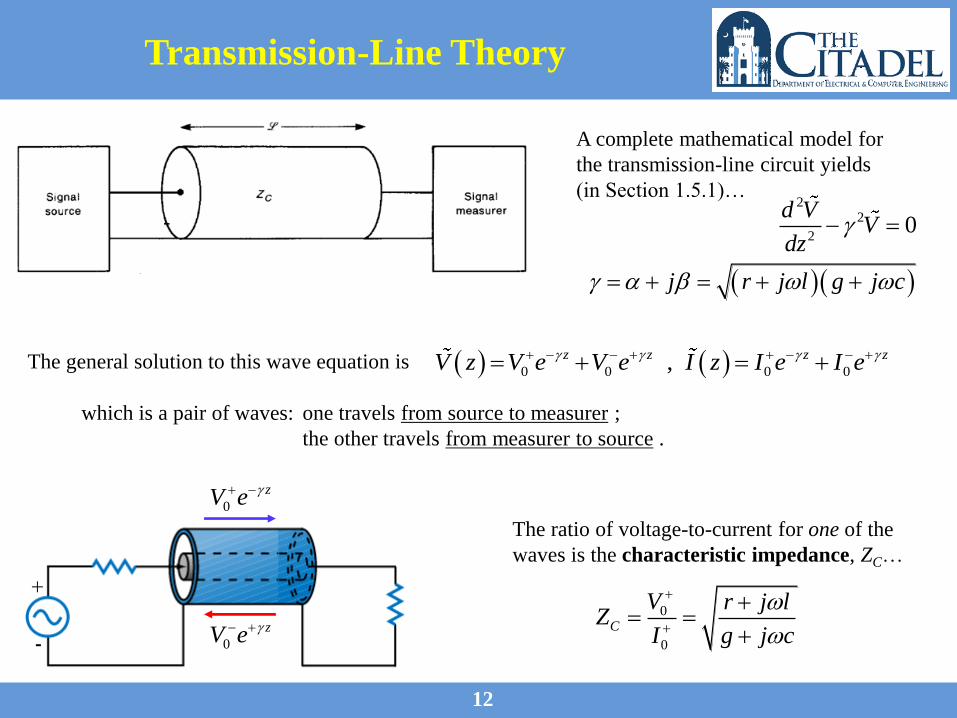
Transmission-Line Theory
The general solution to this wave equation is
The ratio of voltage-to-current for one of the
waves is the characteristic impedance, ZC…
which is a pair of waves: one travels from source to measurer ;
the other travels from measurer to source .
0
0
C
V r j lZ
I g j c
A complete mathematical model for
the transmission-line circuit yields
(in Section 1.5.1)…
22
20
d VV
dz
j r j l g j c
0 0 0 0,z z z zV z V e V e I z I e I e
0
zV e
0
zV e
13
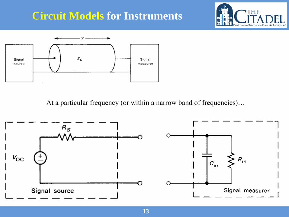
Circuit Models for Instruments
At a particular frequency (or within a narrow band of frequencies)…

14
Matched System (50 W)
When all impedances are matched, the solution is
0
zV e
which is one wave, traveling from source to measurer .
A system is matched when the
Thevenin impedance of the source,
the characteristic impedance, and the
Thevenin impedance of the measurer
are equal.
Our industry standard is 50 W.
0 0,z zV z V e I z I e For a mismatched load/cable, the signal
source output may be determined using
15
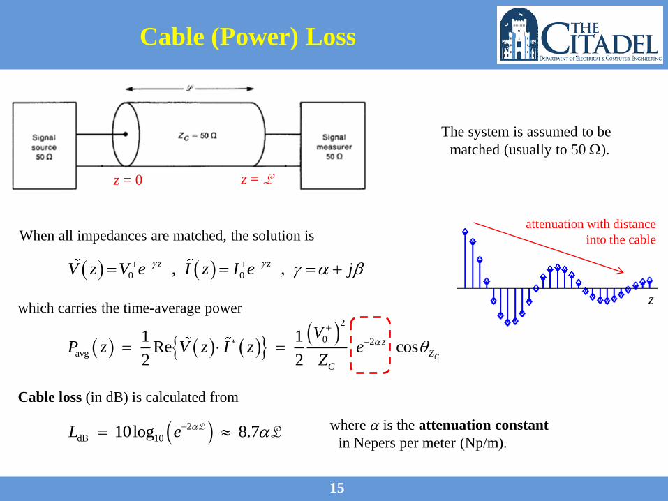
Cable (Power) Loss
When all impedances are matched, the solution is
0 0, ,z zV z V e I z I e j
2
0 2
avg
1 1Re cos
2 2 C
z
Z
C
VP z V z I z e
Z
which carries the time-average power
attenuation with distance
into the cable
z
z = 0 z = L
Cable loss (in dB) is calculated from
2
dB 1010log 8.7L e LL where is the attenuation constant
in Nepers per meter (Np/m).
The system is assumed to be
matched (usually to 50 W).

16
Example: Cable Loss
A 50-W source is attached to a 50-W signal measurer with 300 ft of RG58U coaxial
cable. The source is tuned to a frequency of 100 MHz, and the dial indicates an
output of –15 dBm. At this frequency, the cable loss is 4.5 dB / 100 ft.
Determine the (RMS) voltage at the input to the signal measurer in dBmV.
dB
mW 10
dB
μV 10
10log1 mW
20log1μV
PP
vV

18
Example: Signal Source Output
A 50-W source is attached to a measurer whose input impedance is 25 W.
The dial on the signal generator indicates that it is outputting a level of –20 dBm.
Determine the (RMS) voltage at the input to the signal measurer in dBmV.