elc 311 - communications (1) - modern academyeng.modern-academy.edu.eg/e-learning/comm/comm1...
TRANSCRIPT

ELC 311 - Communications (1)
Prepared by:
•Prof. Dr. Adel El-Sherif
• Dr. Nelly Muhammad Hussein
Modern Academy for Engineering and Technology
Electronics Engineering and Communication Technology Dpt.

Chapter [1]
“Introduction to Communications”
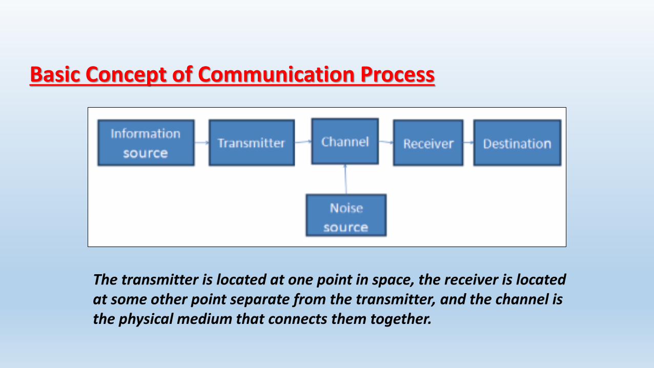
Basic Concept of Communication Process
The transmitter is located at one point in space, the receiver is located at some other point separate from the transmitter, and the channel is the physical medium that connects them together.
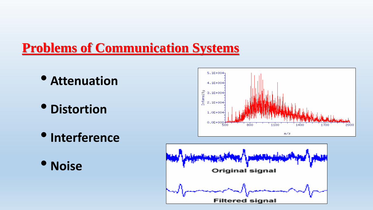
Problems of Communication Systems
• Attenuation
• Distortion
• Interference
• Noise
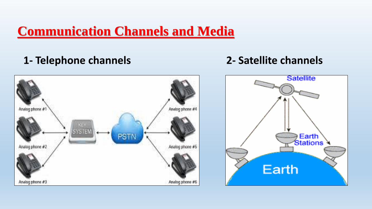
Communication Channels and Media
1- Telephone channels 2- Satellite channels

3- Optical Fiber channels 4- Mobile channels
We may classify communication channels in different
ways:
•A channel may be linear or nonlinear.
•A channel may be time invariant or time varying.
•A channel may be bandwidth limited or power limited.

Baseband and Passband Signals

Analog and Digital Messages
Noise immunity of Digital Signals

Viability of regenerative repeaters in digital comm.
Analog and Digital Messages

Analog-to-digital (A/D) conversion
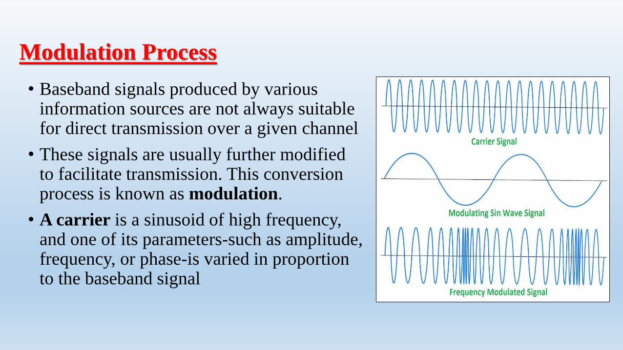
Modulation Process
• Baseband signals produced by various information sources are not always suitable for direct transmission over a given channel
• These signals are usually further modified to facilitate transmission. This conversion process is known as modulation.
• A carrier is a sinusoid of high frequency, and one of its parameters-such as amplitude, frequency, or phase-is varied in proportion to the baseband signal

1- Ease of Radiation
For efficient radiation of electromagnetic energy, the radiating antenna should be on the order of one-tenth or more of the wavelength of the signal radiated.
For many baseband signals, the wavelengths are too large for reasonable antenna dimensions.
Instead, we modulate a high-frequency carrier, thus translating the signal spectrum to the region of carrier frequencies resulting in smaller antenna dimensions.
Benefits of Modulation Process
2- Simultaneous Transmission of Several Signals or multiplexing
If the various carrier are chosen sufficiently fat apart in frequency, the spectra of the modulated signals will not overlap. This method of transmitting several signals simultaneously is known as frequency -division multiplexing (FDM).
Another method of multiplexing several signals is known as time-division multiplexing (TDM).
Benefits of Modulation Process

Chapter [2]
“Amplitude Modulation”

Baseband vs Passband Transmission
• Baseband signals:• Voice (0-4kHz)• TV (0-6 MHz)
• A signal may be sent in its baseband format when a dedicated wired channel is available.
• Otherwise, it must be converted to passband.
Modulation: What and Why?
• The process of shifting the baseband signal to passband range is called Modulation.
• The process of shifting the passband signal to baseband frequency range is called Demodulation.
• Reasons for modulation:• Simultaneous transmission of several signals• Practical Design of Antennas• Exchange of power and bandwidth

Types of (Carrier) Modulation
• In modulation, one characteristic of a signal (generally a sinusoidal wave) known as the carrier is changed based on the information signal that we wish to transmit (modulating signal).
• That could be the amplitude, phase, or frequency, which result in Amplitude modulation (AM), Phase modulation (PM), or Frequency modulation (FM). The last two are combined as Angle Modulation
Types of Amplitude Modulation (AM)
• Double Sideband with carrier (we will call it AM): This is the most widely used type of AM modulation. In fact, all radio channels in the AM band use this type of modulation.
• Double Sideband Suppressed Carrier (DSBSC): This is the same as the AM modulation above but without the carrier.
• Single Sideband (SSB): In this modulation, only half of the signal of the DSBSC is used.
• Vestigial Sideband (VSB): This is a modification of the SSB to ease the generation and reception of the signal.

Double Sideband Suppressed Carrier (DSBSC)
• Assume that we have a message signal m(t) with bandwidth 2B rad/s (or B Hz). m(t) M().
• Let c(t) be a carrier signal, c(t) = cos(ct), c >> 2B
• gDSBSC (t) = m(t)cos(ct)
(1/2) [M( – c) + M( + c)].Xm(t)
c(t)
gDSBSC
(t)
DSBSC Modulator (transmitter)
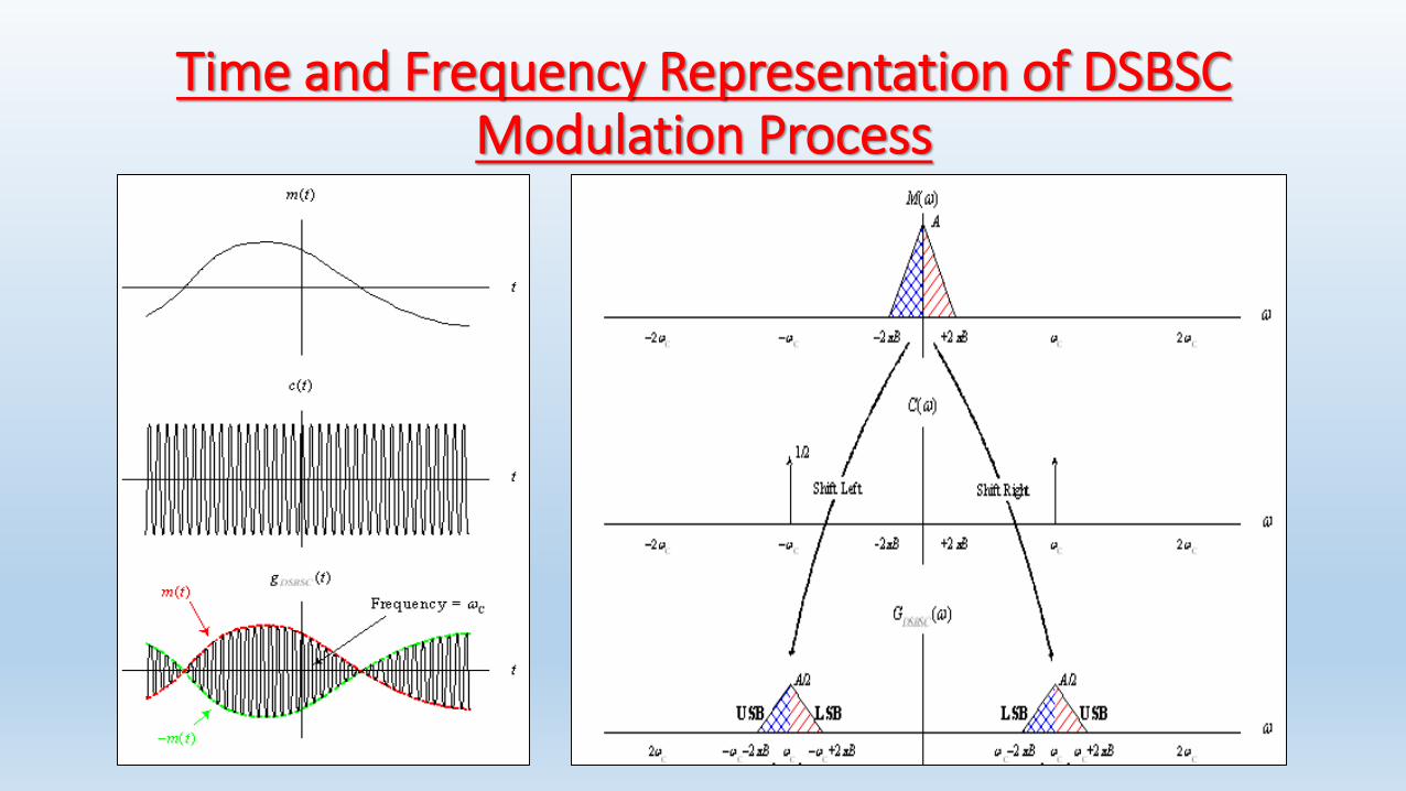
Time and Frequency Representation of DSBSC Modulation Process
DSBSC Demodulation
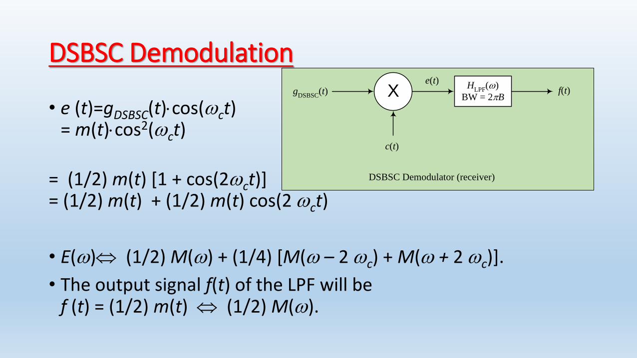
• e (t)=gDSBSC(t)cos(ct) = m(t)cos2(ct)
= (1/2) m(t) [1 + cos(2ct)]= (1/2) m(t) + (1/2) m(t) cos(2 ct)
• E() (1/2) M() + (1/4) [M( – 2 c) + M( + 2 c)].
• The output signal f(t) of the LPF will bef (t) = (1/2) m(t) (1/2) M().
X
c(t)
gDSBSC
(t)e(t)
HLPF
()
BW = 2Bf(t)
DSBSC Demodulator (receiver)

Time and Frequency Representation of DSBSC Demodulation Process

Modulator Circuits
• Basically we are after multiplying a signal with a carrier.
• There are three realizations of this operation:• Multiplier Circuits• Non-Linear Circuits• Switching Circuits

Non-Linear Devices (NLD)
• A NLD is a device whose input-output relation is non-linear. One such example is the diode (iD=evD/vT).
• The output of a NLD can be expressed as a power series of the input, that isy(t) = ax(t) + bx2(t) + cx3(t) + …
• When x(t) << 1, the higher powers can be neglected, and the output can be approximated by the first two terms.
• When the input x(t) is the sum of two signal, m(t)+c(t), x2(t) will have the product term m(t)c(t)
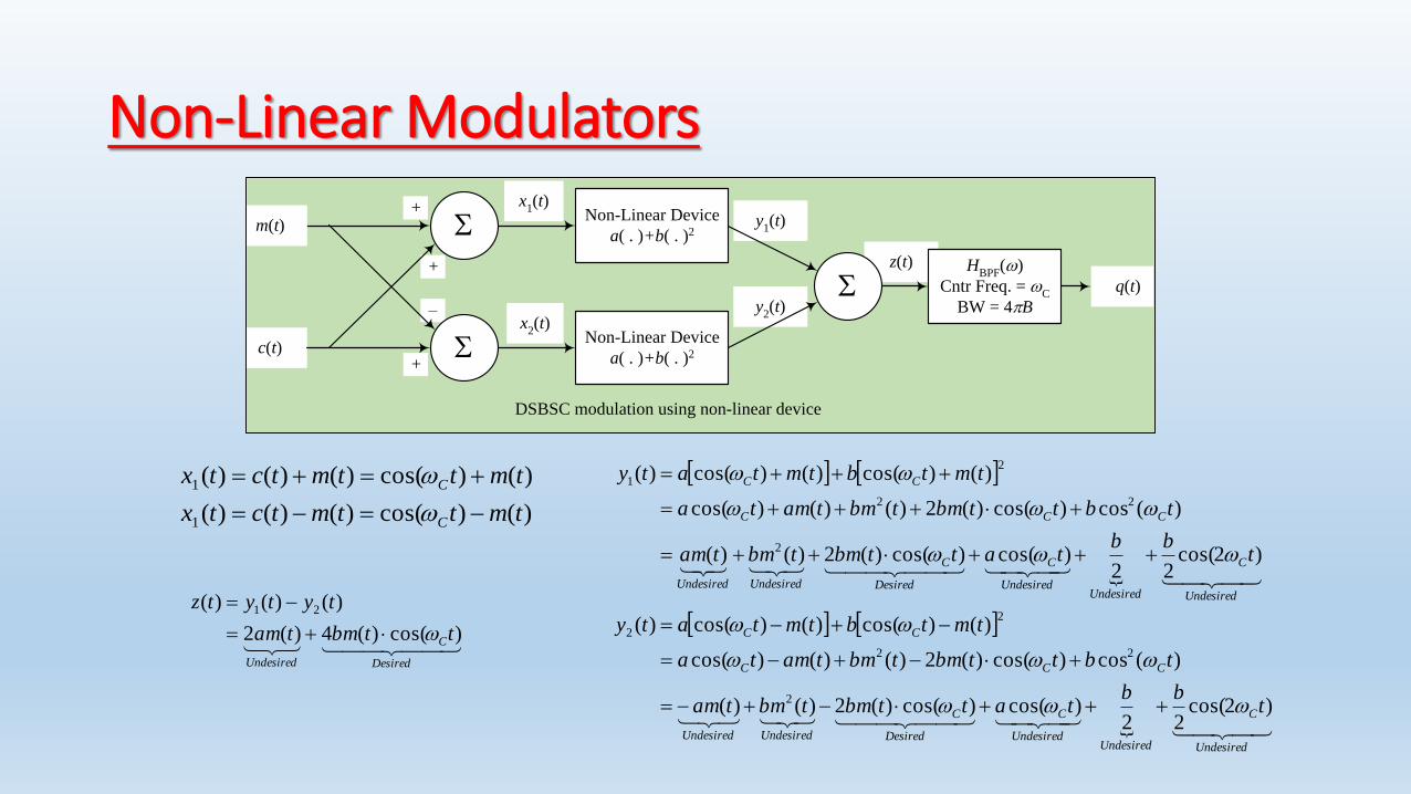
Non-Linear Modulators
+ z(t)
y1(t)
y2(t)
+
–
DSBSC modulation using non-linear device
Non-Linear Device
a( . )+b( . )2
HBPF
()
Cntr Freq. = C
BW = 4B
m(t)
c(t)
x1(t)
q(t)
Non-Linear Device
a( . )+b( . )2
x2(t)
+
Undesired
C
UndesiredUndesired
C
Desired
C
UndesiredUndesired
CCC
CC
Undesired
C
UndesiredUndesired
C
Desired
C
UndesiredUndesired
CCC
CC
tbb
tattbmtbmtam
tbttbmtbmtamta
tmtbtmtaty
tbb
tattbmtbmtam
tbttbmtbmtamta
tmtbtmtaty
)2cos(22
)cos()cos()(2)()(
)(cos)cos()(2)()()cos(
)()cos()()cos()(
)2cos(22
)cos()cos()(2)()(
)(cos)cos()(2)()()cos(
)()cos()()cos()(
2
22
2
2
2
22
2
1
)()cos()()()(
)()cos()()()(
1
1
tmttmtctx
tmttmtctx
C
C
Desired
C
Undesired
ttbmtam
tytytz
)cos()(4)(2
)()()( 21
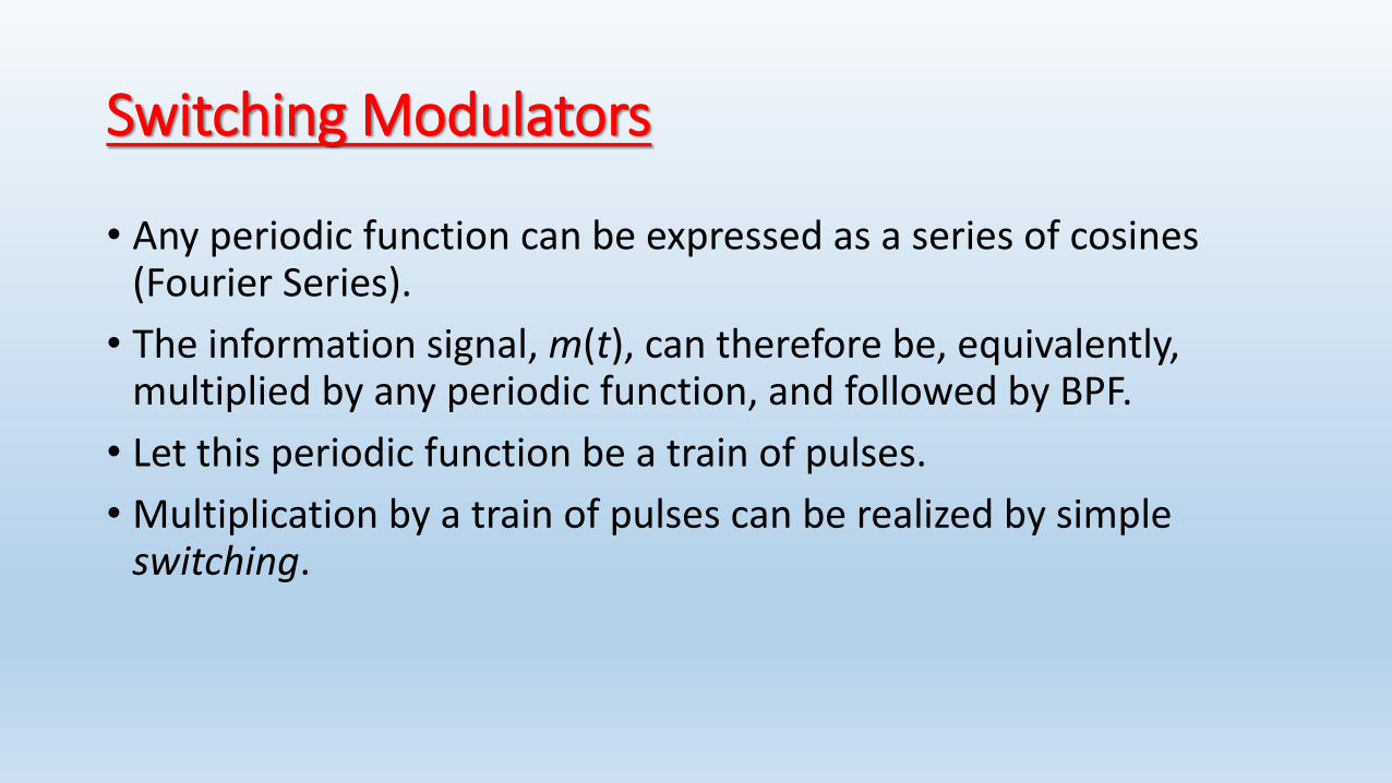
Switching Modulators
• Any periodic function can be expressed as a series of cosines (Fourier Series).
• The information signal, m(t), can therefore be, equivalently, multiplied by any periodic function, and followed by BPF.
• Let this periodic function be a train of pulses.
• Multiplication by a train of pulses can be realized by simple switching.
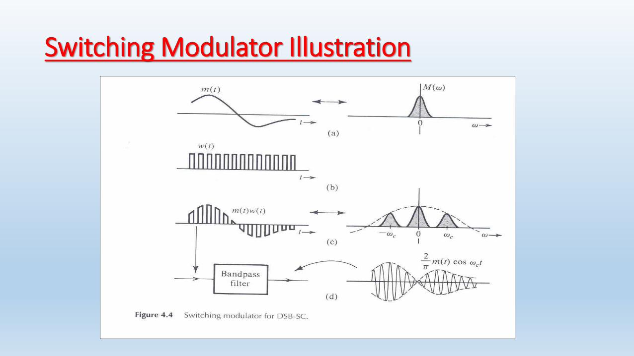
Switching Modulator Illustration
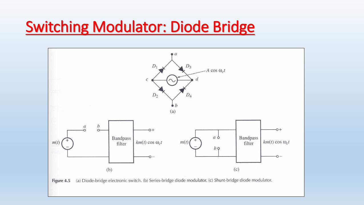
Switching Modulator: Diode Bridge
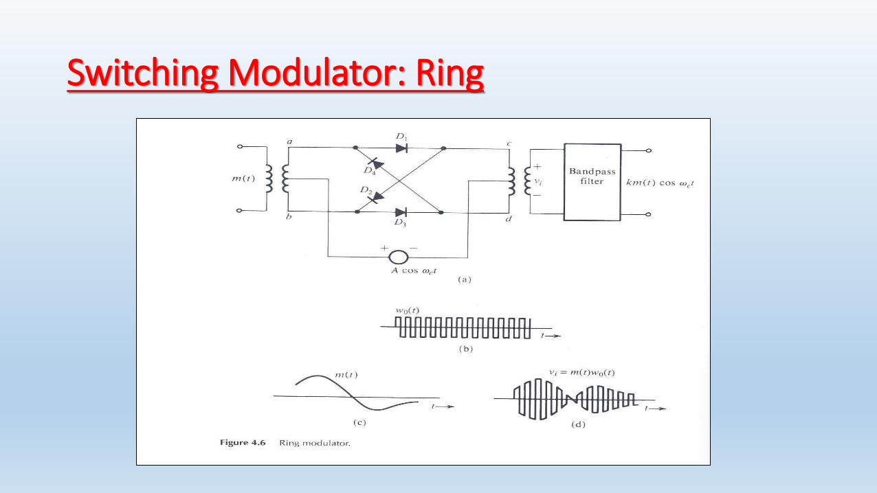
Switching Modulator: Ring

Demodulation of DSBSC• The modulator circuits can be used
for demodulation, but replacing the BPF by a LPF of bandwidth B Hz.
• The receiver must generate a carrier frequency in phase and frequency synchronization with the incoming carrier.
• This type of demodulation is therefore called coherentdemodulation (or detection).
X
c(t)
gDSBSC
(t)e(t)
HLPF
()
BW = 2Bf(t)
DSBSC Demodulator (receiver)
From DSBSC to DSBWC (AM)
• Carrier recovery circuits, which are required for the operation of coherent demodulation, are sophisticated and could be quite costly.
• If we can let m(t) be the envelope of the modulated signal, then a much simpler circuit, the envelope detector, can be used for demodulation (non-coherent demodulation).
• How can we make m(t) be the envelope of the modulated signal?
Definition of AM
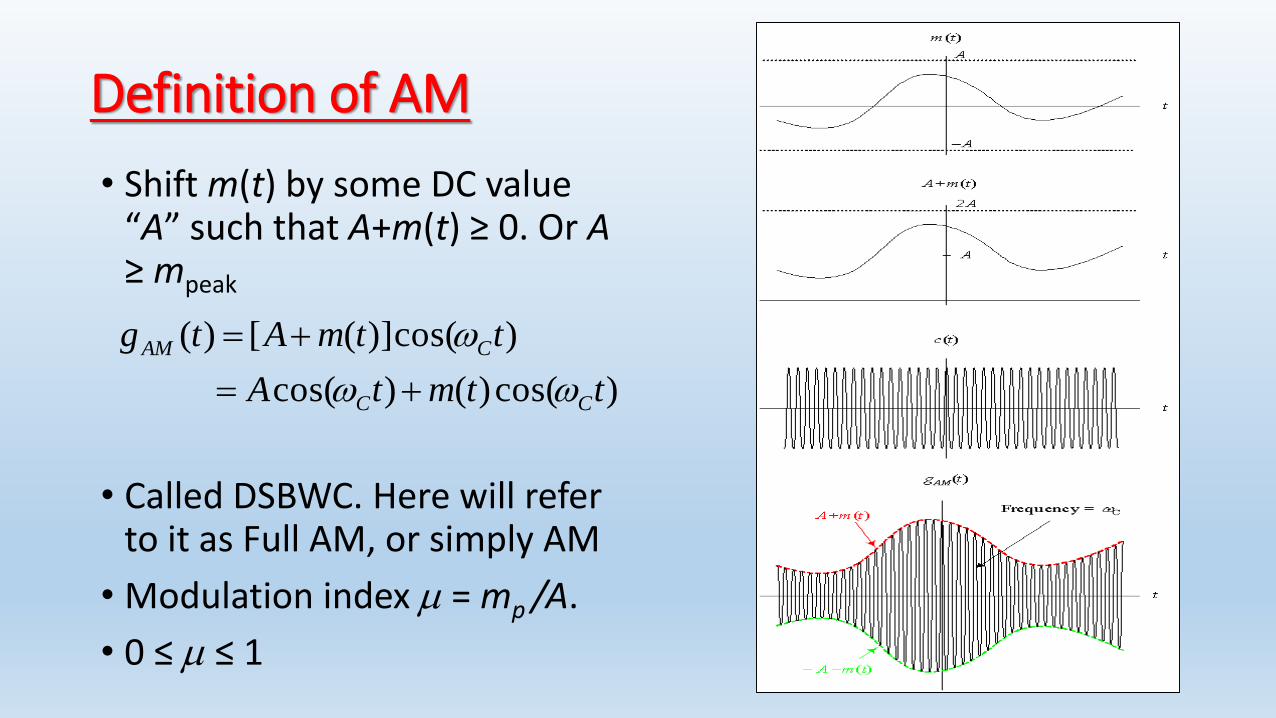
• Shift m(t) by some DC value “A” such that A+m(t) ≥ 0. Or A≥ mpeak
• Called DSBWC. Here will refer to it as Full AM, or simply AM
• Modulation index m = mp /A.
• 0 ≤ m ≤ 1
)cos()()cos(
)cos()]([)(
ttmtA
ttmAtg
CC
CAM
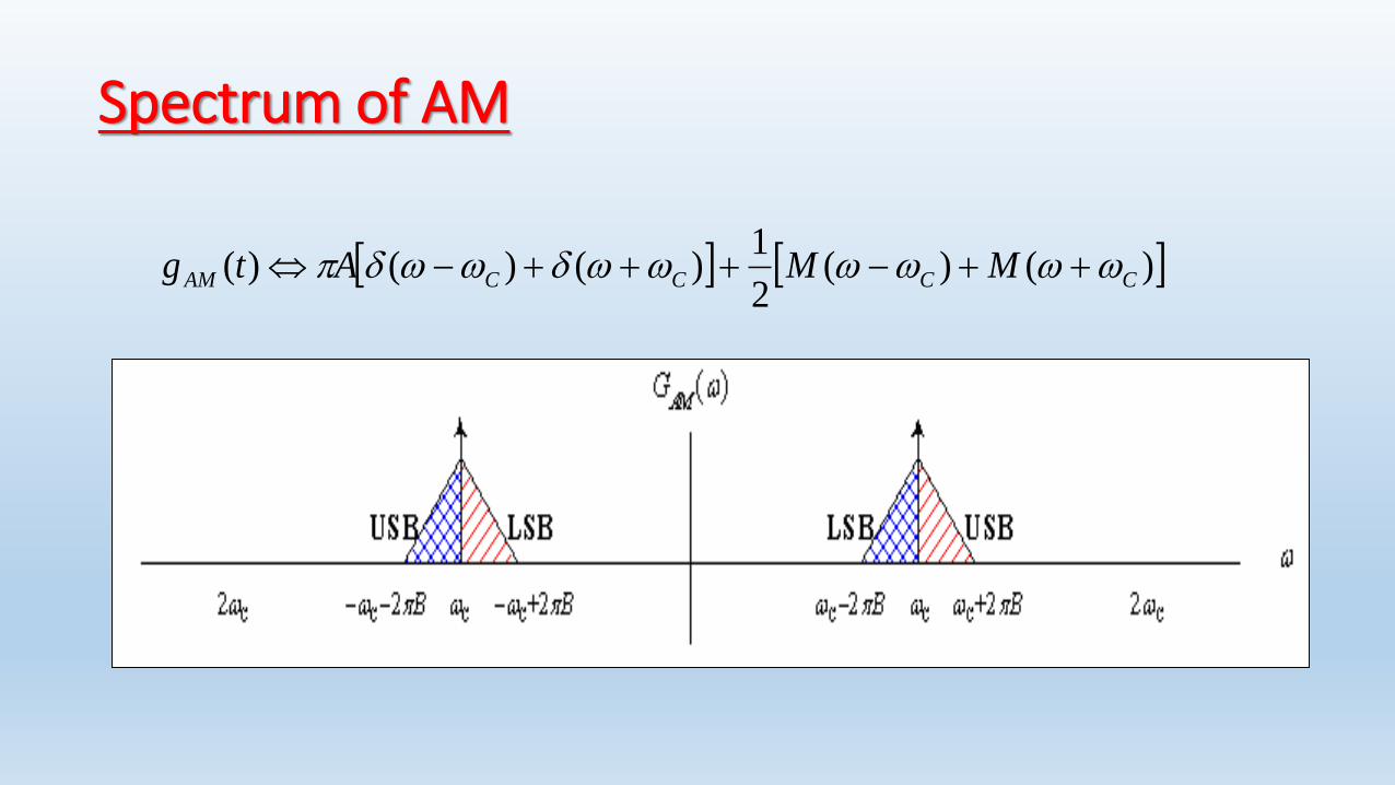
Spectrum of AM
)()(2
1)()()( CCCCAM MMAtg

Advantage and Disadvantage of AM
• Adv.: Simplicity in demodulation.
• Disadv.: Waste in Power
gAM(t) = Acosct + m(t) cosct
Carrier Power Pc = A2/2 (carries no information)
Sideband Power Ps = Pm/2 (useful)
Power efficiency = h = Ps/(Pc + Ps)= Pm/(A2 +Pm)
Generation of AM
• AM signals can be generated by any DSBSC modulator, by using A+m(t) as input instead of m(t).
• In fact, the presence of the carrier term can make it even simpler. We can use it for switching instead of generating a local carrier.
• The switching action can be made by a single diode instead of a diode bridge.

AM Generator
• A >> m(t) (to ensure switchingat every period).
• vR=[cosct+m(t)][1/2 + 2/(cosct-1/3cos3ct + …)]
=(1/2)cosct+(2/)m(t) cosct + other terms (suppressed by BPF)
• vo(t) = (1/2)cosct+(2/)m(t) cosct
cos(ct)
m(t)
R BPF vo(t)
A
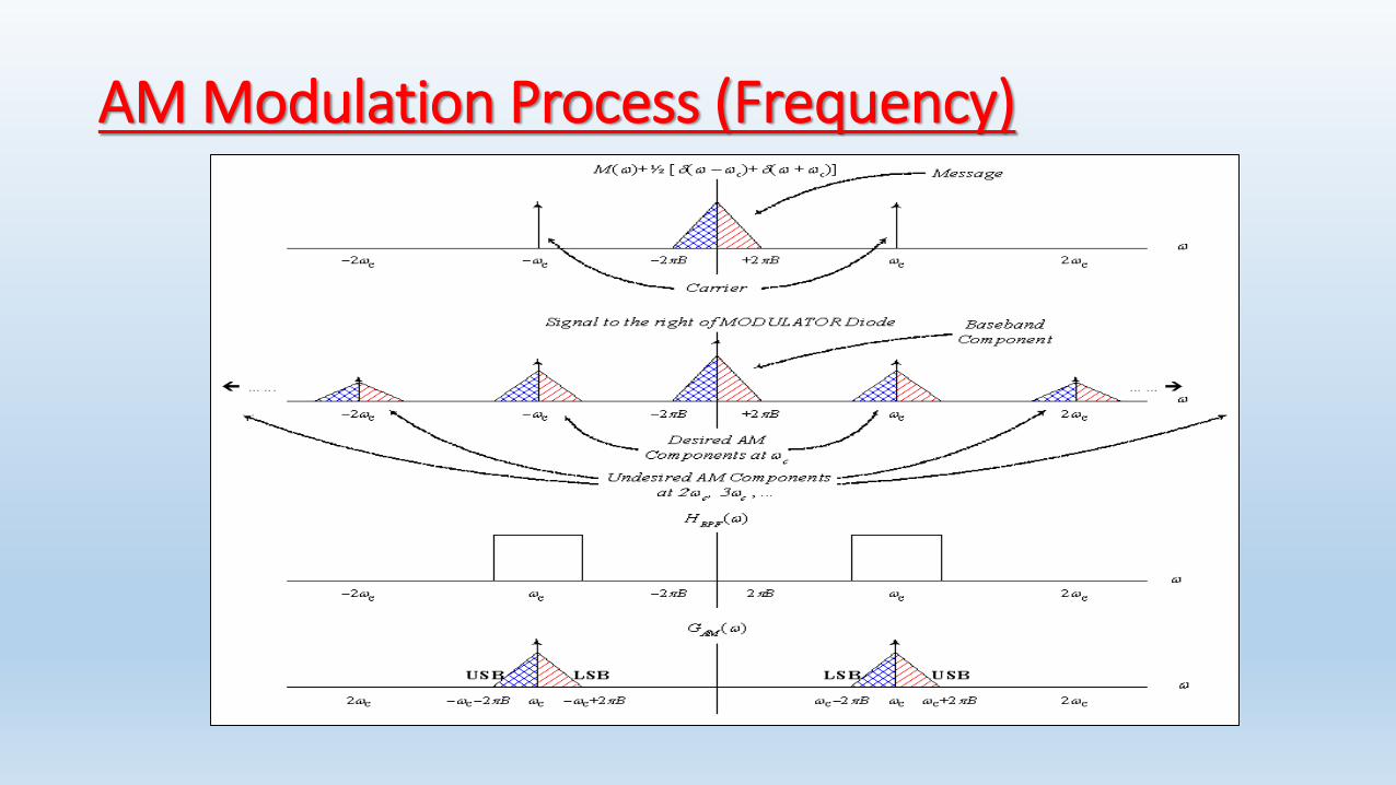
AM Modulation Process (Frequency)
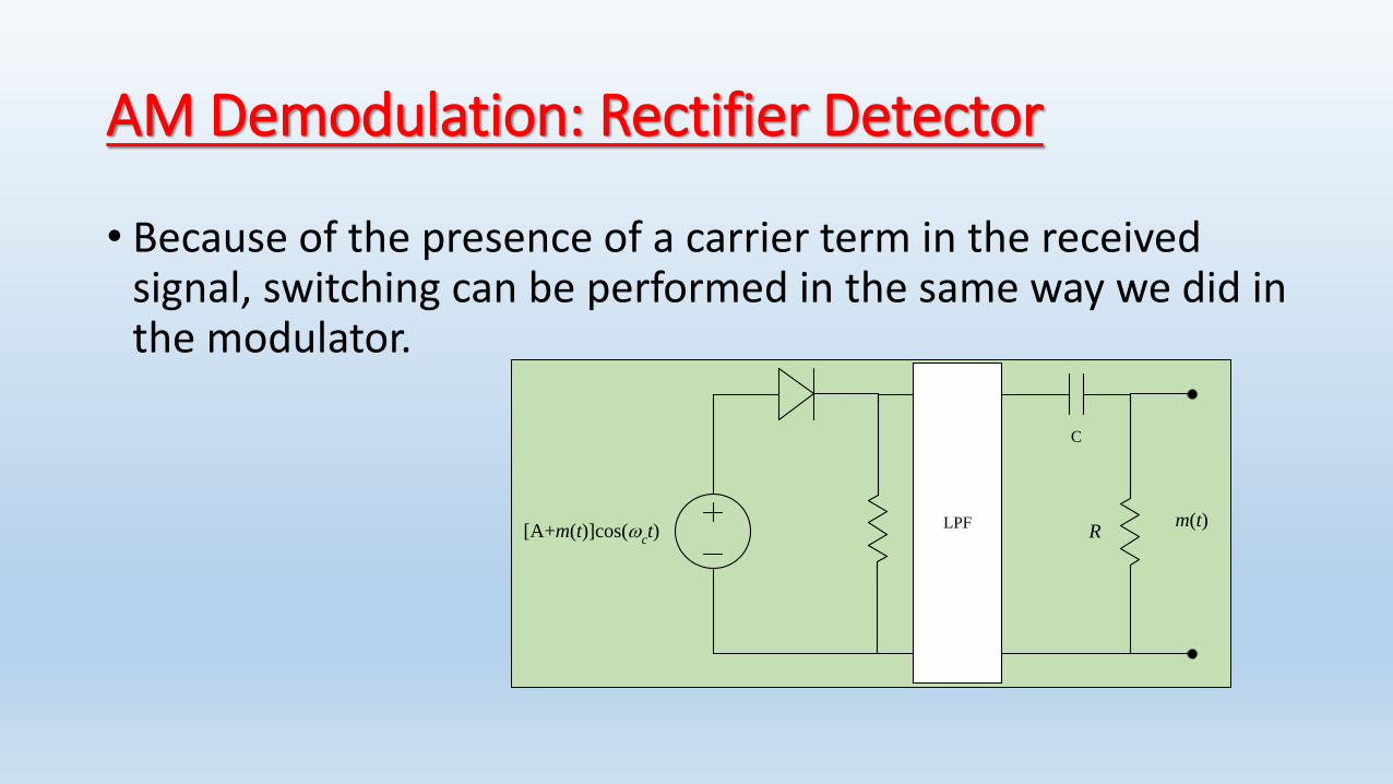
AM Demodulation: Rectifier Detector
• Because of the presence of a carrier term in the received signal, switching can be performed in the same way we did in the modulator.
[A+m(t)]cos(ct)
LPF m(t)
C
R

Rectifier Detector: Time Domain

Rectifier Detector (Frequency Domain)
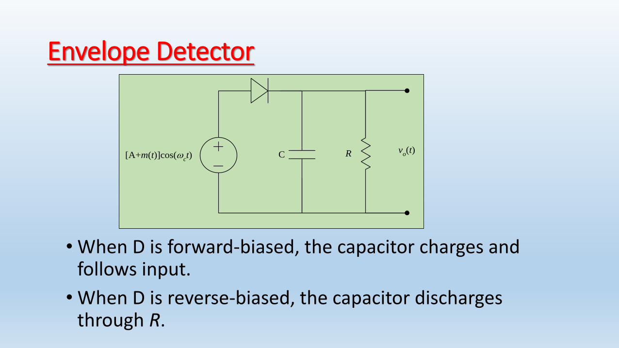
Envelope Detector
• When D is forward-biased, the capacitor charges and follows input.
• When D is reverse-biased, the capacitor discharges through R.
[A+m(t)]cos(ct)
vo(t)RC

Envelope Detection• The operations of the circuit requires
careful selection of t=RC
• If RC is too large, discharging will be slow and the circuit cannot follow a decreasing envelope.
• When RC is too small the ripples will be high.
• 1/(2B) << t << 1/c
• The ripples are finally removed by LPF.
• The DC value is blocked by a capacitor.

Single-Side Band (SSB) Modulation
• DSBSC (as well as AM) occupies double the bandwidth of the baseband signal, although the two sides carry the same information.
• Why not send only one side, the upper or the lower?
• Modulation: similar to DSBSC. Only change the settings of the BPF (center frequency, bandwidth).
• Demodulation: similar to DSBSC (coherent)

SSB Representation
How would we represent the SSB signal in the time domain?
gUSB(t) = ?
gLSB(t) = ?

Time-Domain Representation of SSB (1/2)M() = M+() + M-()
Let m+(t)↔M+() and m-(t)↔M-()
Then: m(t) = m+(t) + m-(t) [linearity]
Because M+(), M-() are not even
m+(t), m-(t) are complex.
Since their sum is real they must be
conjugates.
m+(t) = ½ [m(t) + j mh(t)]
m-(t) = ½ [m(t) - j mh(t)]
What is mh(t) ?

Time-Domain Representation of SSB (2/2)M() = M+() + M-()
M+() = M()u(); M-() = M()u(-)
sgn()=2u() -1 u()= ½ + ½ sgn(); u(-) = ½ -½ sgn()
M+() = ½[ M() + M()sgn()]
M-() = ½ [M() - M()sgn()]
Comparing to:
m+(t) = ½ [m(t) + j mh(t)] ↔ ½ [M() + j Mh()]
m-(t) = ½ [m(t) - j mh(t)] ↔ ½ [M() - j Mh()]
We find
Mh() = - j M()∙sgn() where mh(t)↔Mh()

Time-Domain Operation for Hilbert Transformation
For Hilbert Transformation H() = -j sgn().
What is h(t)?
sgn(t) ↔ 2/(j) [From FT table]
2/(jt) ↔ 2 sgn(-) [symmetry]
1/( t) ↔ -j sgn()
Since Mh() = - j M()∙sgn() = H() ∙ M()
Then
dt
m
tmt
tmh
)(1
)(*1
)(

)sin()()cos()(
)(2
1)(
2
1
)(2
1)(
2
1)(
)sin()()cos()(
)(2
1)(
2
1
)(2
1)(
2
1)(
ttmttm
etjmetm
etjmetmtg
ttmttm
etjmetm
etjmetmtg
ChC
tj
h
tj
tj
h
tj
LSB
ChC
tj
h
tj
tj
h
tj
USB
CC
CC
CC
CC
)()()(
)()()(
CCLSB
CCUSB
MMG
MMG
tjtj
LSB
tjtj
USB
CC
CC
etmetmtg
etmetmtg
)()()(
)()()(
Finally …

Generation of SSB
• Selective Filtering MethodRealization based on spectrum analysis
• Phase-Shift MethodRealization based on time-domain expression of the modulated signal

Phase-shifting Method: Frequency-Domain Illustration
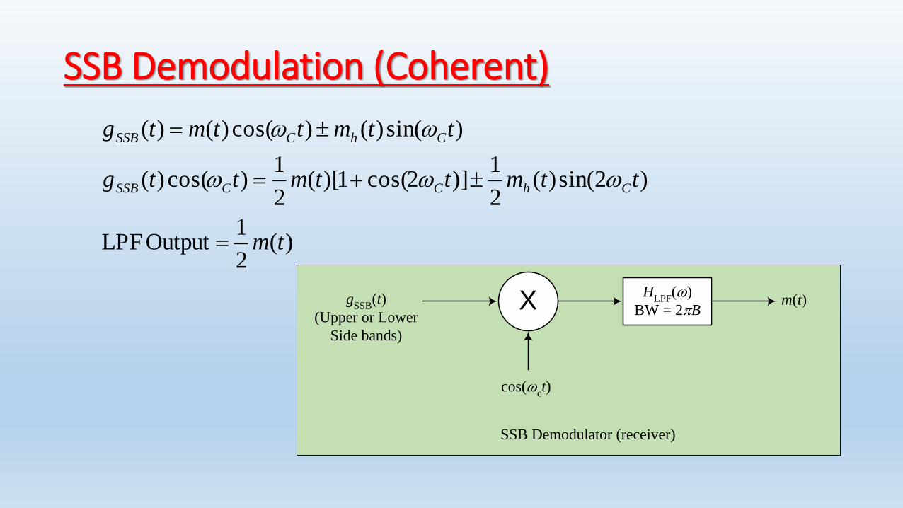
SSB Demodulation (Coherent)
X
cos(ct)
gSSB
(t)
(Upper or Lower
Side bands)
HLPF
()
BW = 2Bm(t)
SSB Demodulator (receiver)
)(2
1 Output LPF
)2sin()(2
1)]2cos(1)[(
2
1)cos()(
)sin()()cos()()(
tm
ttmttmttg
ttmttmtg
ChCCSSB
ChCSSB
Vestigial Side Band Modulation (VSB)
• What if we want to generate SSB using selective filtering but there is no guard band between the two sides?We will filter-in a vestige of the other band.
• Can we still recover our message, without distortion, after demodulation?Yes. If we use a proper LPF.

Filtering Condition of VSB
X
2cos(ct)
m(t)H
VSB()
(BPF)g
VSB(t)
VSB Modulator (transmitter)
gDSBSC
(t)
X
2cos(ct)
gVSB
(t)H
LPF()
BW = 2Bm(t)
VSB Demodulator (receiver)
x(t)
)cos()(2)( ttmtg CDSBSC
)()()( CCDSBSC MMG
)()()()( CCVSBVSB MMHG
C
C
at
C
baseband
CVSB
Basebandat
CCVSB
MMH
MMHX
2
2
)2()()(
)()2()()(
)()()()()( MHHHZ CVSBCVSBLPF
)()(
1)(
CVSBCVSB
LPFHH
H
; || ≤ 2 B
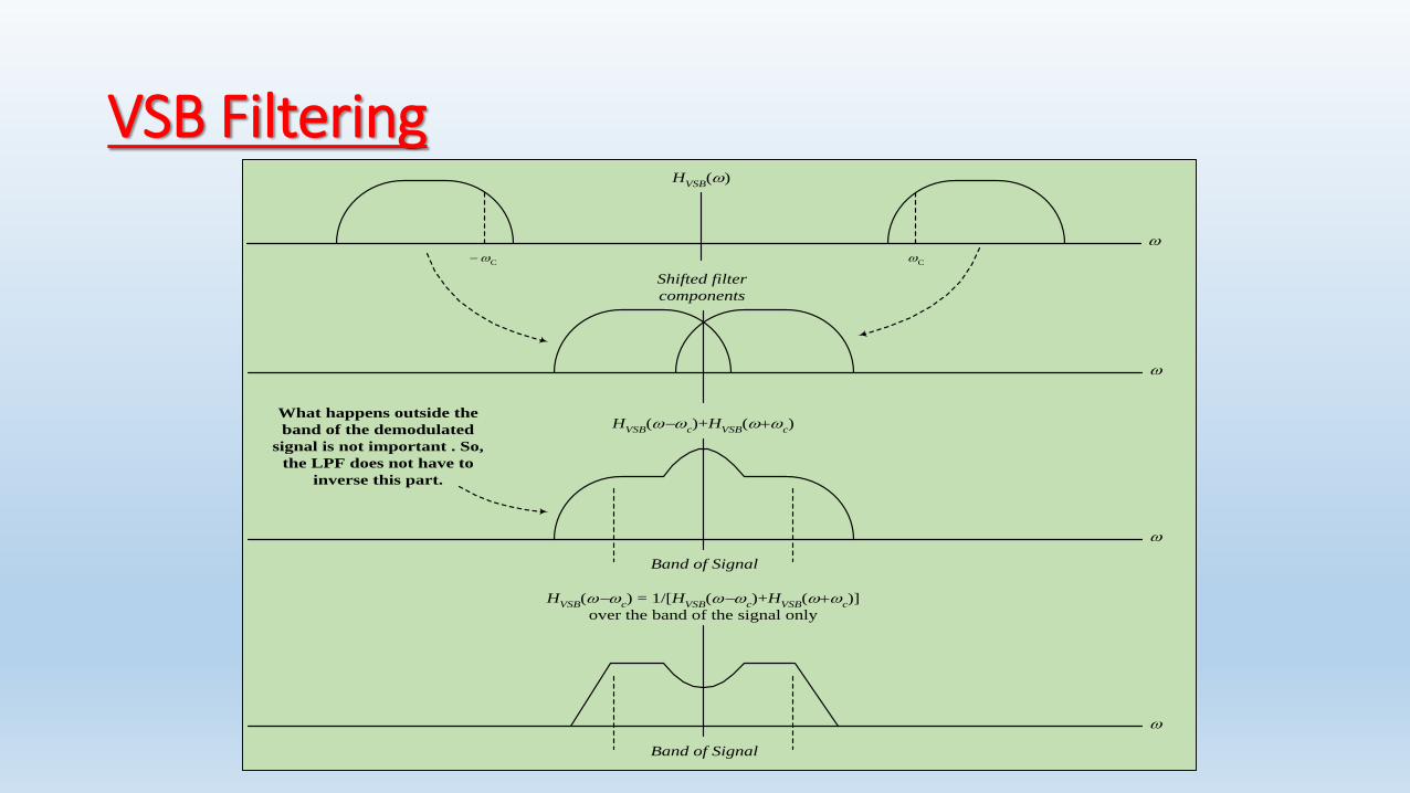
VSB FilteringH
VSB()
C
C
HVSB
(c)+H
VSB(
c)
Shifted filter
components
Band of Signal
HVSB
(c) = 1/[H
VSB(
c)+H
VSB(
c)]
over the band of the signal only
Band of Signal
What happens outside the
band of the demodulated
signal is not important . So,
the LPF does not have to
inverse this part.

VSB Filter: Special Case
• Condition For distortionless demodulation:
• If we impose the condition on the filter at the modulator:
HVSB(c) + HVSB(c) = 1 ; || ≤ 2 B
Then HLPF = 1 for || ≤ 2 B (Ideal LPF)
• HVSB() will then have odd symmetry around c over the transition period.
)()(
1)(
CVSBCVSB
LPFHH
H
; || ≤ 2 B
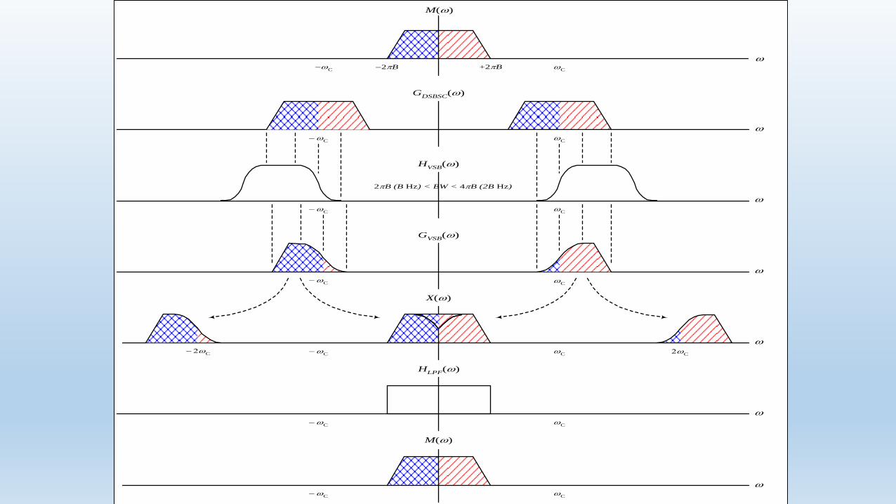
GDSBSC
()
C
C
M()
+2B
2B
C
C
HVSB
()
2B (B Hz) < BW < 4B (2B Hz)
C
C
GVSB
()
C
C
X()
C
C
C
M()
C
C
HLPF
()
C
C
C
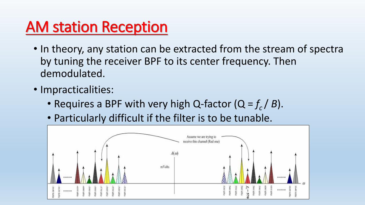
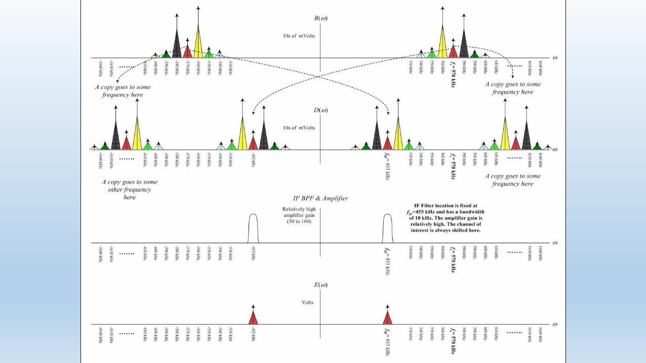
AM station Reception• In theory, any station can be extracted from the stream of spectra
by tuning the receiver BPF to its center frequency. Then demodulated.
• Impracticalities:• Requires a BPF with very high Q-factor (Q = fc / B).• Particularly difficult if the filter is to be tunable.
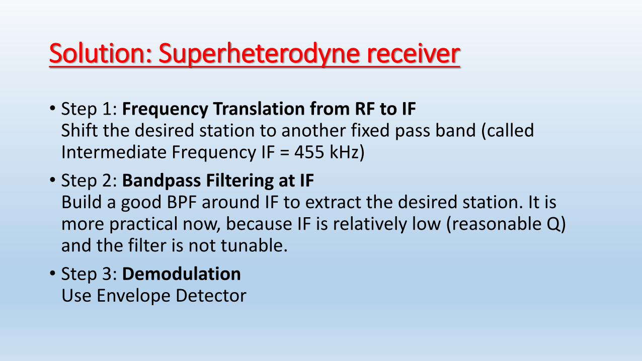
Solution: Superheterodyne receiver
• Step 1: Frequency Translation from RF to IFShift the desired station to another fixed pass band (called Intermediate Frequency IF = 455 kHz)
• Step 2: Bandpass Filtering at IFBuild a good BPF around IF to extract the desired station. It is more practical now, because IF is relatively low (reasonable Q) and the filter is not tunable.
• Step 3: DemodulationUse Envelope Detector
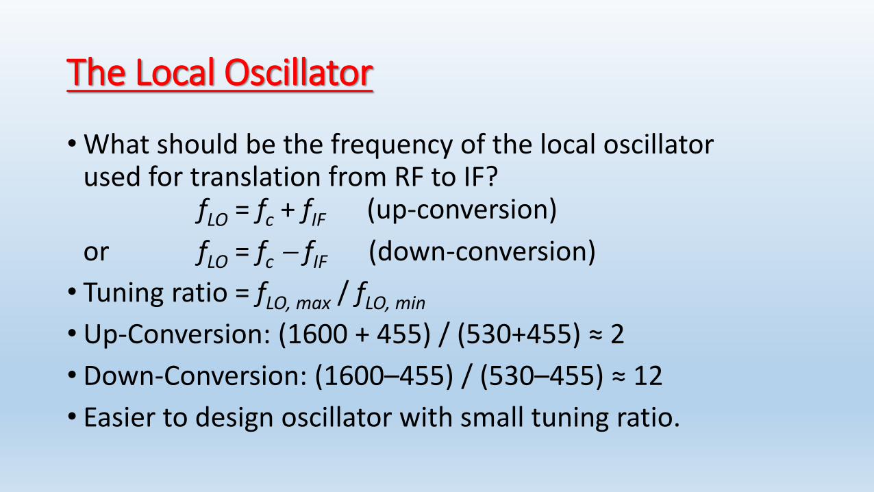
The Local Oscillator
•What should be the frequency of the local oscillator used for translation from RF to IF?
fLO = fc + fIF (up-conversion)
or fLO = fc fIF (down-conversion)
• Tuning ratio = fLO, max / fLO, min
• Up-Conversion: (1600 + 455) / (530+455) ≈ 2
• Down-Conversion: (1600–455) / (530–455) ≈ 12
• Easier to design oscillator with small tuning ratio.
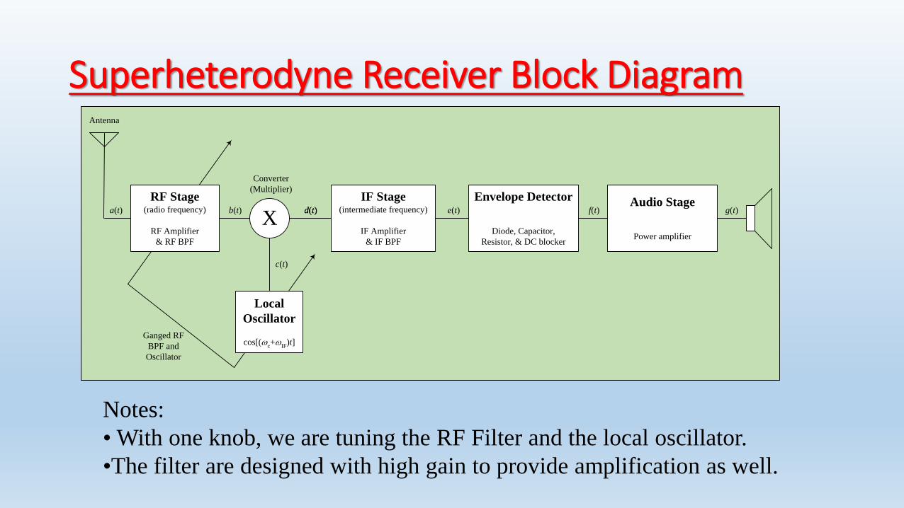
Superheterodyne Receiver Block DiagramAntenna
IF Stage(intermediate frequency)
IF Amplifier
& IF BPF
X
Converter
(Multiplier)
a(t) b(t) d(t)
c(t)
Envelope Detector
Diode, Capacitor,
Resistor, & DC blocker
Audio Stage
Power amplifier
d(t) e(t) f(t) g(t)
Ganged RF
BPF and
Oscillator
RF Stage(radio frequency)
RF Amplifier
& RF BPF
Local
Oscillator
cos[(c+
IF)t]
Notes:
• With one knob, we are tuning the RF Filter and the local oscillator.
•The filter are designed with high gain to provide amplification as well.


Chapter [3]
“Angle Modulation: Frequency Modulation
and Phase Modulation”
ANGLE MODULATION• When frequency or phase of the carrier is varied by the
modulating signal , then it is called angle modulation.
• Frequency Modulation – When the frequency of the carrier varies as per amplitude of modulating signal, then it is called frequency modulation (FM).
• Phase Modulation - When the phase of the carrier varies as per amplitude of modulating signal, then it is called phase modulation (PM).
• Amplitude of the modulated carrier remains constant in both modulation systems.
BDG(xx) 67
Important feature of angle modulation:• It can provide a better discrimination (robustness)
against noise and interference than AM.
• This improvement is achieved at the expense of increased transmission bandwidth.
• In case of angle modulation, channel bandwidth may be exchanged for improved noise performance
• Such trade-off is not possible with AM
BDG(xx) 68

BASIC DEFINITIONS• Sinusoidal carrier c(t) =Ac cos[θi(t)]
• Angle of carrier θi(t)[rad]
• Instantaneous frequency of carrier fi(t) =(1/2π)ωi(t) =(1/2π)di(t)/dt
• =(1/2π)˙ θi(t)[Hz].
• In the case of an un-modulated carrier, the angle becomes θi(t) = 2πfct + θc
BDG(xx) 69

Time domain representation
70BDG(xx)
Comparison between FM and PM:
• The basic difference between FM & PM lies in which property of the carrier is directly varied by modulating signal.
• In FM, the frequency of carrier is varied directly.
• In PM, phase of the carrier is varied directly. Instantaneous phase deviation is represented by θ(t).
• Instantaneous phase= ωct + θ(t) rad.
BDG(xx) 71
• Instantaneous frequency deviation =
• d/dt {θ(t)} = θ’(t) Hz.
• The instantaneous frequency deviation is the instantaneous change in carrier frequency and is equal to the rate at which instantaneous phase deviation takes place.
• Instantaneous frequency is defined as frequency of the carrier at a given instant of time and is given as ωi(t) =d/dt [ωc.t + θ(t)] = ωc + θ’(t) rad/sec.
BDG(xx) 72

• Instantaneous phase deviation θ (t) is proportional to modulating signal voltage, θ (t) = k em(t) rad. ( k is deviation sensitivity of phase.)
• Instantaneous frequency deviation θ’ (t) is proportional to modulating signal voltage, θ’ (t) = k1 em(t) rad. ( k1 is deviation sensitivity of frequency.)##2
BDG(xx) 73
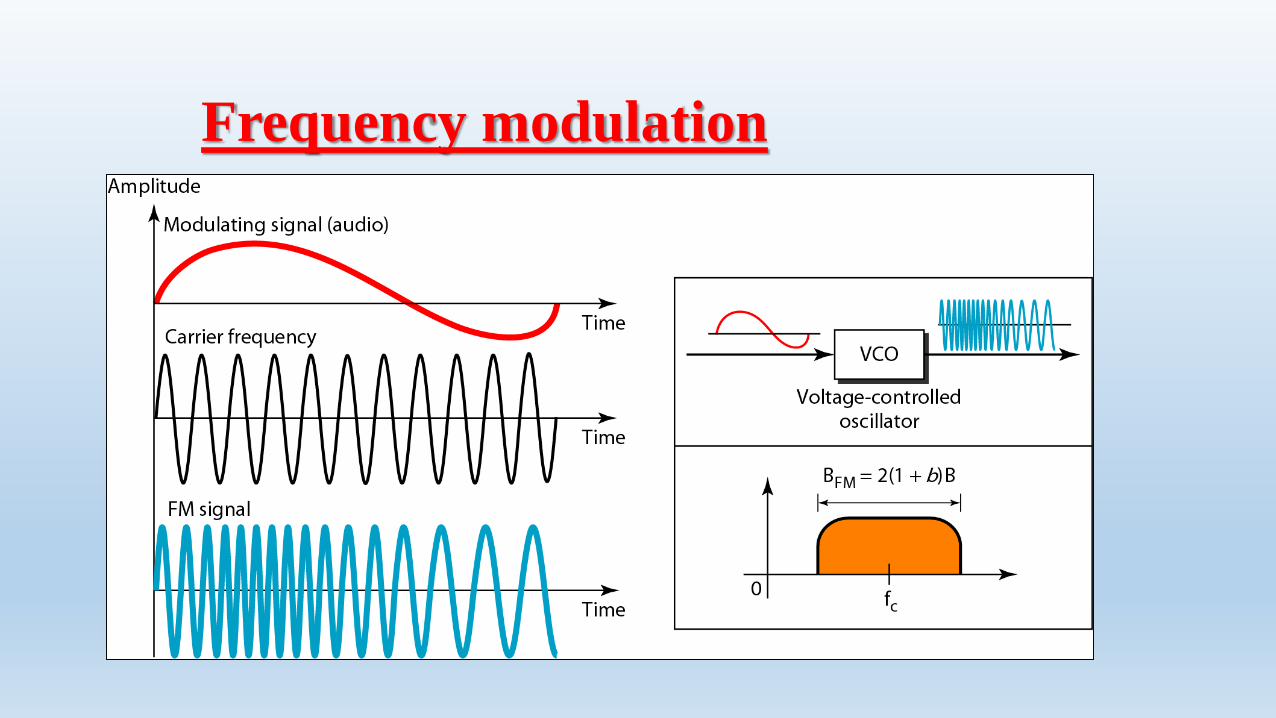
Frequency modulation

Observations from the FM & PM waveforms
1. Both FM & PM waveforms are identical except the phase shift.
2. For FM, the maximum frequency deviation takes place when modulating signal is at +ve and –vepeaks.
3. For PM, the maximum frequency deviation takes place near zero crossing of the modulating signal.
4. It is diffcult to know from modulated waveform whether the modulation is FM or PM. (##3)
BDG(xx) 76

Bandwidth Requirement – for FM and PM• The BW requirement can be obtained depending on the
modulation index (M.I).
• The M.I. can be classified as high(more than 10), medium (1 to 10) and low (less than 1).
• The low index systems are called narrowband FM in which frequency spectrum resembles AM. BW (fm) =2fm Hz.
• For high index modulation, BW = 2*δ.(Freq. dev.)
• BW can also be found out by Bessel table- BWfm = 2.n.fm where n is the number of sidebands obtained from table.
• Bandwidth for PM –
• BW for PM is expressed as
• BWpm = 2(mp+1)fm.
BDG(xx) 77

NBFM Generator
79
IntegratorProduct
Modulator
90 degree Phase Shifter
Carrier Generator
Adder M(t)NBFM signal
Wideband Frequency Modulation
• If the modulation index is higher than 10, then it is called wideband FM.
• Spectrum contains infinite numbers of sidebands and carrier as against two sidebands and carrier in NBFM.
• BW is = 2{δ+fm(max)} as against 2fm for NBFM.
• Used for broadcast and entertainment as against for mobile communication for NBFM.
BDG(xx) 80

Advantages of Angle Modulation over AM-
1. As the amplitude of FM carrier is constant, the noise interference is minimum.
2. The amplitude of FM carrier is constant and is independent of depth of modulation. Hence transmitter power remains constant in FM whereas it varies in AM.
3. As against the limitation of depth of modulation in AM, in FM depth of modulation can be increased to any value, without causing any distortion.
81

4. Because of guard bands provided in FM, adjacent channel interference is very less.
5. Since FM uses VHF and UHF bands of frequencies, the noise interference is minimum as compared to AM which uses MF and HF ranges.
6. Radius of propagation is limited as FM uses space waves with line of sight. So it is possible to operate many independent transmitters on the same frequency with minimum interference.
82
Disadvantages of FM compared to AM
1. BW requirement of FM is very high as compared to AM.
2. FM equipments are more complex and hence costly.
3. Area covered by FM is limited, to line of sight area but AM coverage area is large.
BDG(xx) 83
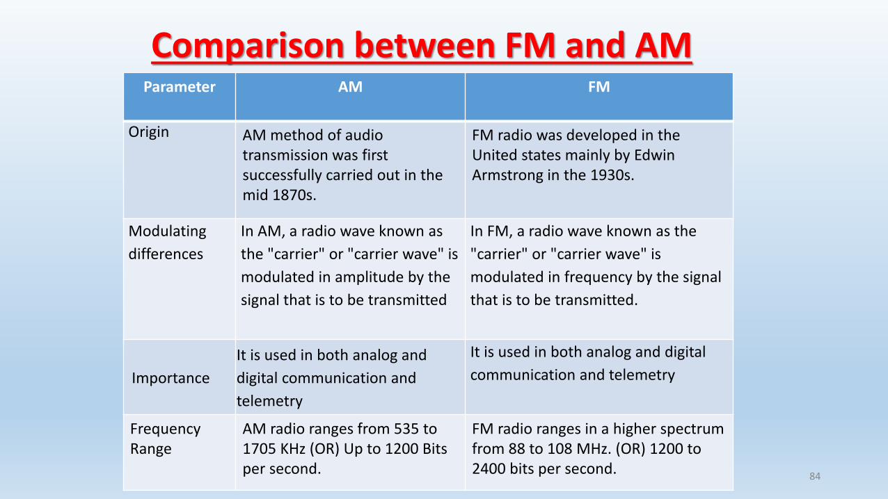
Comparison between FM and AM
BDG(xx) 84
Parameter AM FM
Origin AM method of audio transmission was first successfully carried out in the mid 1870s.
FM radio was developed in the United states mainly by Edwin Armstrong in the 1930s.
Modulating
differences
In AM, a radio wave known as
the "carrier" or "carrier wave" is
modulated in amplitude by the
signal that is to be transmitted
In FM, a radio wave known as the
"carrier" or "carrier wave" is
modulated in frequency by the signal
that is to be transmitted.
Importance
It is used in both analog and
digital communication and
telemetry
It is used in both analog and digital
communication and telemetry
Frequency Range
AM radio ranges from 535 to 1705 KHz (OR) Up to 1200 Bits per second.
FM radio ranges in a higher spectrum from 88 to 108 MHz. (OR) 1200 to 2400 bits per second.
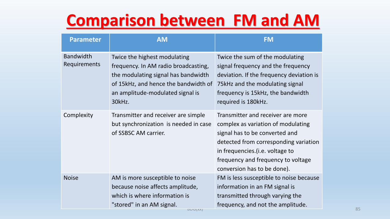
Comparison between FM and AM -
BDG(xx) 85
Parameter AM FM
Bandwidth Requirements
Twice the highest modulating
frequency. In AM radio broadcasting,
the modulating signal has bandwidth
of 15kHz, and hence the bandwidth of
an amplitude-modulated signal is
30kHz.
Twice the sum of the modulating
signal frequency and the frequency
deviation. If the frequency deviation is
75kHz and the modulating signal
frequency is 15kHz, the bandwidth
required is 180kHz.
Complexity Transmitter and receiver are simple
but synchronization is needed in case
of SSBSC AM carrier.
Transmitter and receiver are more
complex as variation of modulating
signal has to be converted and
detected from corresponding variation
in frequencies.(i.e. voltage to
frequency and frequency to voltage
conversion has to be done).
Noise AM is more susceptible to noise
because noise affects amplitude,
which is where information is
"stored" in an AM signal.
FM is less susceptible to noise because
information in an FM signal is
transmitted through varying the
frequency, and not the amplitude.
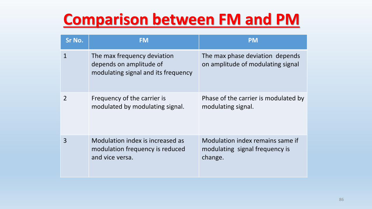
Comparison between FM and PM
86
Sr No. FM PM
1 The max frequency deviation depends on amplitude of modulating signal and its frequency
The max phase deviation depends on amplitude of modulating signal
2 Frequency of the carrier is modulated by modulating signal.
Phase of the carrier is modulated by modulating signal.
3 Modulation index is increased as modulation frequency is reduced and vice versa.
Modulation index remains same if modulating signal frequency is change.