elbereth: tool support for refactoring java programs
TRANSCRIPT

Elbereth: Tool Support for Refactoring Java Programs�
Walter Korman and William G. Griswold
Department of Computer Science & Engineering, 0114
University of California, San Diego
San Diego, CA 92093-0114 USA
(619) 534-6898
fwkorman,[email protected]
Abstract
As object-oriented software is modified its structure tends to degrade. The potentially large number
of classes and the large number of dependencies between them can complicate the analysis and planning
needed to maintain a program written in an object-oriented language.
Restructuring software to improve its design can lower the cost of future changes. To ease the task
of software restructuring, we describe the application of thestar diagramconcept to Java programs. The
star diagram visualization affords programmers a cross-cutting view of the project source code that can
simplify software maintenance tasks by allowing the programmer to rapidly assess complicated class
hierarchies and complex class interrelationships. The recording of detailed refactoring tasks to be per-
formed, accompanied by relevant portions of star diagrams for the source code undergoing modification,
provides the programmer with a visualization of the work that assists in recall and execution of the
software restructuring.
Research submission.
Keywords: programming environments, software engineering practices, experience with object-oriented
applications and systems.
�This research is supported in part by NSF grant CCR-9508745.

1 Introduction
1.1 The Problem
Software is difficult and costly to change. Large software projects face challenges such as larger develop-
ment teams, greater scope of software functionality, and competition-driven schedules. These issues often
lead to decreased cohesion and increased coupling between classes. The source code grows more difficult to
maintain, and the addition of new features becomes increasingly complex. Delegation of programming tasks
among programmers is made more difficult by the large number of classes and dependencies between them.
Programming tasks performed by more than one person are also more likely to suffer from inconsistencies
in coding style, information-hiding methodology, and naming, which compromises the conceptual integrity
of the software product. The intrinsic difficulty of good object-oriented design in complex systems is em-
phasized by the growing popularity of design patterns, which can impart experience and design knowledge
to software designers [Gamma et al. 93].
Opdyke proposes that refactoring existing class hierarchies can improve their maintainability and reusabil-
ity [Opdyke 92, Opdyke & Johnson 90]. A refactoring activity changes the organization of an object-
oriented program without changing its behavior. It includes changes such as encapsulating public refer-
ences to member data in a new method or creating abstract superclasses from shared behavior in similar
classes. Refactorings can be performed proactively by a programmer to ease upcoming changes or they can
be performed as part of a comprehensive reengineering effort. Opdyke’s automated refactoring tool allows
a programmer to guide the automatic refactoring of specific portions of a class hierarchy.
A key problem in refactoring an object-oriented program is first identifying the structural problems with
the current design and then exploring the possible solutions. For example, consider a class that consists
primarily of public data members. As the application evolves and becomes increasingly complex, a better
design for such a class might be to make the member data private and encapsulate the computations on its
data members in methods of that class. To get a sense of what the methods of the class should be, a software
designer needs to view all the references to the data members and categorize them according to how they
are manipulated. However, the uses of the data members are widely distributed throughout the program and
interspersed with computations that are unrelated to the class in question, thereby complicating the analysis.
Opdyke’s refactoring tool provides a mechanism for performing automatic meaning-preserving restruc-
turings, but it does not help the programmer decide which restructurings to perform to improve the design.
Categorization of references with a text editor is difficult because each reference is shown only in the con-
text of its use, rather than with the other references to the class. A typical solution to this problem is to use
2

a searching tool like Unixgrep , which extracts only those program lines that match a specified pattern.
Although successful in removing unrelated code, it is not capable of matching data references by type, only
by name. Also, it does not perform any further categorization of the matched references or suggest which
computations on the references belong inside the class and which should remain outside. A design visual-
ization like a class hierarchy diagram or a graphical object model can reveal the high-level aspects of the
system’scurrentdesign, but it is not possible to use such a view to examine the source code’s latent structure
to suggest an appropriate redesign. Finally, in planning a complex redesign, it is desirable to have support
for recording the designer’s many discoveries, thoughts, and refactoring plans.
1.2 The Star Diagram
For programs written in a procedural programming language, this problem has been addressed by a restruc-
turing tool designed around the star diagram visualization [Bowdidge 95, Bowdidge & Griswold 94]. A star
diagram provides a compact, hierarchical, tree-structured visual representation of the source code relating to
a particular data structure, eliding code unrelated to the data structure’s use and maintenance. Similar code
fragments are merged into “node stacks” to reveal potentially redundant computations. Stacked fragments
are frequently candidates for a refactoring such as abstraction into new methods.
We believe that these techniques can be extended to take advantage of object-oriented constructs, thereby
providing more effective assistance in the maintenance of object-oriented programs. To empirically evalu-
ate these claims we have implementedElbereth[Korman & Griswold], a tool for exploring, planning, and
carrying out refactorings of Java programs [Gosling et al. 96]. Elbereth is based on a restructuring planning
tool for C [Griswold et al. 96, Griswold 97] with enhancements that not only exploit the hierarchical type
information provided by classes and inheritance, but also streamline common refactoring scenarios.
A star diagram is a hierarchical graphical representation of the “references” relation in the program
source for all instances of a given class, primitive type, or other identifier (Figure 1). The root of a star dia-
gram is the node representing all occurrences of the identifier being diagrammed. The children of the root
represent language constructs in the program that directly reference one of the occurrences. The next level
of children represents language constructs that reference the previous level’s computations, and so on. A
node having a stacked appearance indicates that two or more pieces of code correspond to a similar compu-
tation. The penultimate level of children, shown as parallelograms, represents the methods containing these
computations. The last level, displayed as hexagonal nodes, corresponds to the class definitions containing
3

Figure 1: Identifier star diagram for variable “n” in the Elbereth source.
Figure 2: Identifier star diagram for “n” with unstacked, method and class nodes elided.
4

Figure 3: Source corresponding to theField: info � Field: toString � Field: equals arm of Figure 2.
the code seen in that arm.1
For example, the top-most visible arm in Figure 1, labelled left-to-right asn � Field: getId �
== � return, denotes all code of the formreturn(n.getId() == expression) . The stacking of
the nodes on the path reveals the redundancy of the code. The parallelogram nodes following thereturn
node indicate that the methodsisIfStatementNode , isSwitchStatementNode , etc. contain the
instances of this code. The connecting hexagonal node, labelledClassDecl: SDFactory, indicates that all
of these methods occur in the SDFactory class.
A star diagram for all instance variables of a class displays all of the computations that refer directly
or indirectly to those instances, and omits computations not related to the class. Due to the stacking of
similar computations, each unique computation is represented just once. This information can be used by a
programmer in many ways, including:
� Each node in the tree can be interpreted as a possible implementation of an alternate method ab-
straction of the diagrammed class. The redundant code could also be moved into a method in the
referencing class or a third-party class. Nodes near the left of the tree are computations that tend
to denote “lower level” methods, perhaps encapsulating little more than the object representation it-
self. Nodes farther to the right tend to denote “higher level” methods, encapsulating both the object
representation and manipulation.
� The paths in the star diagram represent the class’sde factointerface to the rest of the system. When
faced with replacing a class with one of an incompatible type, it is possible to determine which parts
of the class to be replaced need to be supported by the new class. The star diagram also highlights
those uses of the class that will need to be changed to account for incompatibilities between the old
1We could have chosen to include a final level of nodes representing the file containing the class definition. However, Java
programs typically contain only one class per file, so the information is not often useful.
5

and new class.
� When star diagrams for two classes are viewed side-by-side, their interfaces can be compared for
underlying similarities. This may lead the programmer to factor out a common abstract superclass.
To fully support such scenarios, it is useful to be able to manipulate the star diagram view to focus on
issues of particular interest and also to record the complex plans during the understanding process. Support
for viewing the source text in a number of ways is also useful in providing deeper understanding and helping
to perform changes.
To reduce clutter and clarify the programmer’s view of a class’s uses, the programmer can, for example,
elide the method or class nodes from the diagram (Figure 2). Additionally, the programmer can remove
arms from the diagram by selecting them and clicking theTrim Arm button (described in Section 2.1.)
Arms trimmed in this manner are placed in a separate star diagram window and entered into the Active Plan
panel at the bottom of the main project window.
To help the programmer recall refactoring actions planned for later, star diagrams—including trimmed
arms—can be annotated with text typed in by the programmer. To do this, the programmer clicks the
Annotate Arm button in the project window and enters a note to record the star diagram’s role in the
restructuring. The annotation can usually be kept brief since the arm is stored with the note, providing the
additional context necessary for the programmer to recall their intent.
Since a star diagram provides a rather abstract yet focused representation of a program, it is helpful to
support navigation among the source code representations. We have provided direct-manipulation support to
help the programmer jump from method to method, class to class, and amongst source files at will. Double-
clicking on a star diagram node brings up a source-code summary of all the computations denoted by the
node (Figure 3). Double-clicking a class or method node in a diagram will automatically generate a new
diagram for the class or method node selected, respectively. In addition, star diagrams can be created by
double-clicking on identifiers in the program source or by typing in a string. Program source can be searched
with a regular-expression facility or with a standard class browser, and star diagrams can be created by
double-clicking on any entry in the browser. Trimmed star arms may be manipulated and navigated in the
same manner as full star diagrams, providing the programmer flexibility in assessing or changing a trimmed
arm.
The following section presents several scenarios using Elbereth to refactor its own source code, demon-
strating the approach. Section 3 describes how this approach differs from use of the C star diagram tool and
how this influenced Elbereth’s design. Sections 4 and 5 describe related work and conclusions, respectively.
6

2 Scenarios
The use of Elbereth to aid in the refactoring of object-oriented software is best illustrated by example.
Using Elbereth we have performed substantial refactorings on the tool itself. The following scenarios show
a number of ways that star diagrams can be used to guide the refactoring of programs and demonstrate the
usefulness of the approach.
The refactorings described are commonly found in maintenance of object-oriented software systems.
Our execution of these refactorings effected beneficial design changes that we had not anticipated before-
hand. For purposes of exposition we have chosen simple examples that convey the essential flavor of El-
bereth’s use in reengineering a class hierarchy.
The scenarios presented illustrate:
� Extracting a method. The use of the SimpleNode class was examined in the traversal of Elbereth’s
internal Abstract Syntax Tree (AST) representation. Three sources of major redundancy were found
and addressed with the help of a heavily elided star diagram. The diagram condensed a great deal of
code into a much smaller area and highlighted the key areas requiring consideration. The refactoring
plan resulted in more readable and maintainable source code.
� Extracting an abstract superclass. Redundant functionality in the StarDiagramPanel and Active-
PlanPanel classes was moved into the newly created StarFrameList abstract superclass. StarDiagram-
Panel and ActivePlanPanel became concrete subclasses of StarFrameListPanel. Elbereth aided by
presenting a broad perspective on the use of the classes throughout the rest of the project source code.
It also provided a compact representation of the methods to be considered for abstraction, and showed
that neither class’s member data were directly accessed outside of the classes themselves. Analyzing
the external interfaces of the two classes focused attention on the high-level abstractions represented
by the classes. It also simplified the task of finding method calls external to the class source files
themselves that needed changing as a result of the refactoring.
� Replacing an existing class with an enhanced version.The java.awt.TextArea class provided by the
standard Java programming libraries was useful in getting early versions of Elbereth up and running
but it was not extensible enough (in particular, it could not be effectively subclassed) to support
features desired in later versions of Elbereth. We implemented our own TextArea class to work around
these limitations, replacing our use of the previous TextArea class. Elbereth was used to determine
the portions of the TextArea interface that the new class would have to support and to find the uses of
7

the TextArea class throughout the source code during design of the new TextArea.
We also briefly describe how we used Elbereth to plan the addition of a new subclass. Although Elbereth
is not currently integrated with a tool that performs refactorings for the programmer, it could be used as a
graphical front-end for an automatic restructuring tool [Opdyke 92].
The tool implementation consists of approximately 21,000 lines of source code in 80 files. 12,000 of
these lines and 11 of the files are code produced by the JavaCC parser generator [SunTest]. Since analysis
of the generated files is largely irrelevant from the perspective of software design, we omitted them from
our refactoring projects. The resulting source code then consists of 9,000 lines of source and 69 source files.
This represents one of the largest Java projects publicly available at the time of this writing.
2.1 Extracting a Method
The stacking of nodes representing similar computations in star diagrams can be used for finding code that
may benefit from further abstraction. Class member data or methods are often referenced in a similar fashion
throughout many parts of a software project. Programmers frequently move such redundant operations
into a new method, resulting in more readable and maintainable source code. This refactoring also aids
programmers in finding further refactorings by reducing the code’s complexity.
Method extraction was performed in Elbereth to refactor the SimpleNode class used for Elbereth’s Ab-
stract Syntax Tree (AST) representation. The SimpleNode class is key to much of Elbereth’s functionality,
as the AST is the main data structure that is traversed to build star diagrams. Hence, the class is heavily
referenced throughout the source code. Due to a desire to reduce the amount of redundant code dealing
with the AST nodes, and in an attempt to simplify further extensions to the AST nodes in the future, several
method extractions were performed.
To begin the refactoring, the programmer launches Elbereth and adds the source files to be analyzed to
the project (Figure 4). The programmer first examines theSDFactory.java source file responsible for
the creation of star diagrams. Most of the SimpleNode instances are passed as parameters, so the program-
mer double-clicks on one such parameter namedn to create an identifier diagram for all references ton
(Figure 1).
The initial diagram is too large to easily assimilate, hence the programmer seeks to elide unnecessary
information from the view. There are several approaches to clarifying the diagram, including: (1) the
programmer could use theNode-Hiding Options dialog to remove uninteresting nodes from the diagram;
(2) the programmer could trim irrelevant arms from the diagram; or (3) the programmer could generate a
8
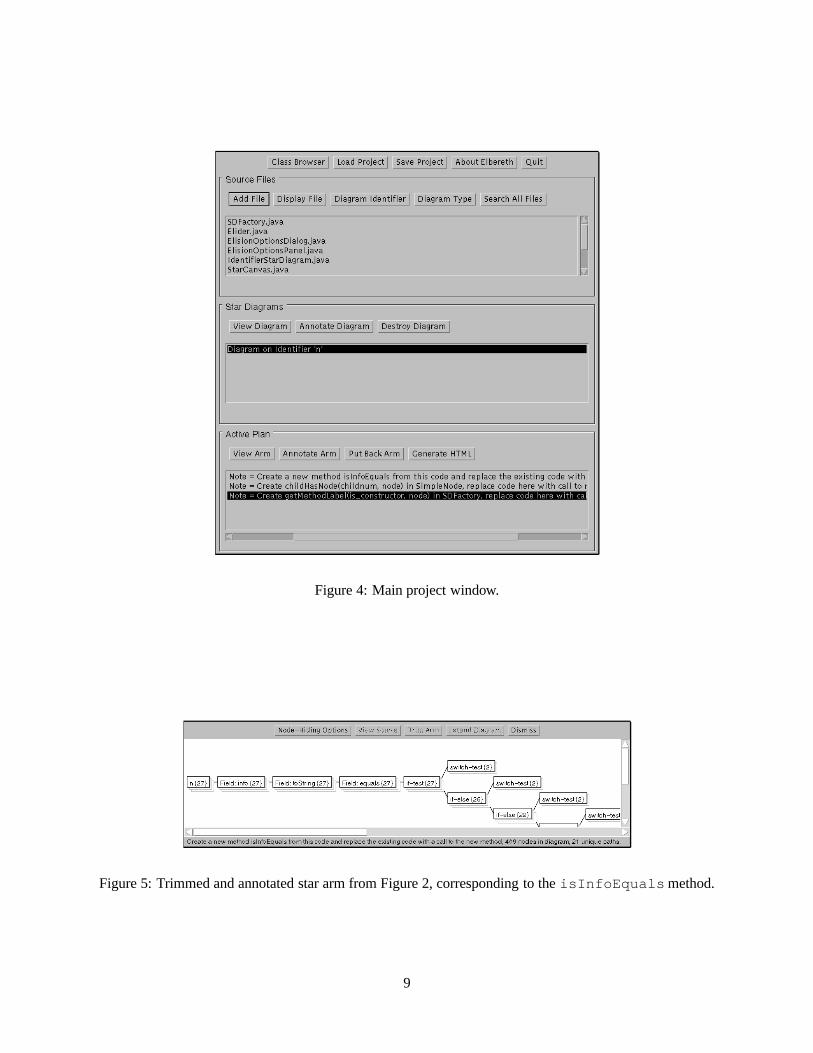
Figure 4: Main project window.
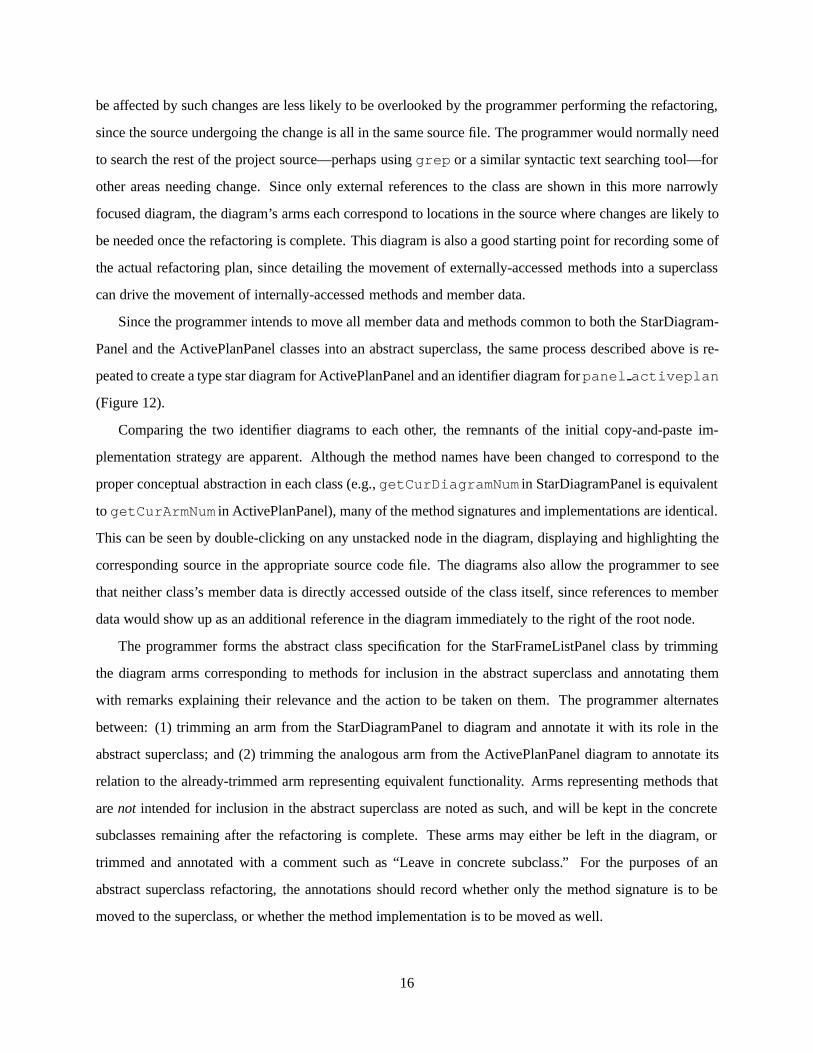
Figure 5: Trimmed and annotated star arm from Figure 2, corresponding to theisInfoEquals method.
9

new diagram for a particular identifier of interest. A common approach is to initially elide the method and
class nodes from the diagram, providing a clear picture of only the operations performed on the root node.
Elided nodes can easily be restored when needed.
In this case, the programmer chooses to elide currently irrelevant nodes with theNode-Hiding Options
dialog. The programmer feels that locality of reference is unimportant for now, so method and class nodes
are removed. Unstacked nodes are removed as well, leaving only nodes likely to denote redundant code
(Figure 2). Elided nodes can be put back later if desired.
In the elided star diagram the programmer can see all operations performed onn in the open source
files. The most deeply-stacked arm is theField: info � Field: toString � Field: equals arm, so
the programmer chooses to examine that arm first. Double-clicking on theequals node stack brings up
the corresponding source code (Figure 3). The source reveals that theinfo field of every AST node in
question is being converted to a string via thetoString method and then compared to another string via
theequals method. This operation could be more cleanly encapsulated as anisInfoEquals method
within the SimpleNode class. This will shorten the code in SDFactory dramatically. Also, the method
implementation could later be rewritten for greater performance (e.g., to better handle large star diagrams.)
So, the programmer selects theField: equals node and clicks theTrim Arm button to trim the path. Clicking
theAnnotate Arm button in the project window, the programmer adds the annotation “Create a new method
isInfoEquals from this code and replace the existing code with a call to the new method”. The arm annotation
appears in the project window’s Active Plan panel as well as at the bottom of the star arm window itself
(Figure 5). The Active Plan panel contains a chronological listing of the tasks, whereas a single arm and its
annotation represents a single task to be performed.
According to this particular trimmed arm and its accompanying annotation, then, the programmer in-
tends to later add the following method definition to the SimpleNode class:
public boolean isInfoEquals(String str) {return (info.toString().equals(str));
}
The jjtGetChild � subtreeHasNode arm is the next most deeply-stacked arm. Looking at the
source code corresponding to thesubtreeHasNode node stack (Figure 6), the programmer sees that an
explicit typecast is taking place, a particular child (either0 or 1) of the node in question is being accessed,
and the child’s subtree is thereafter searched for a particular node (prev , in all cases shown.) A better
encapsulation here might be a new methodchildHasNode in the SimpleNode class. The method could
take two parameters to specify which child number to reference, and the node to be found in the child’s
10

Figure 6: Source corresponding to thesubtreeHasNode node in Figure 2.
Figure 7: Star Diagram onn after extracting theisInfoEquals andchildHasNode methods.
Figure 8: Source corresponding to thejjtGetParent node in Figure 7.
11

subtree. Use of this new method would remove the need for the explicit typecast and double-dereference
seen in the current code. The programmer trims the arm and enters, “Create childHasNode(childnum, node)
in SimpleNode, replace code here with call to new method.”
The programmer has now found two major sources of redundancy and recorded detailed plans for a better
design. The star diagram onn provides the programmer with a visualization of the areas still remaining for
consideration, as the arms already addressed are removed from the diagram when trimmed (Figure 7).
Moving to the next candidate arm, the programmer considers the arm beginning with thejjtGetPar-
ent node. The arm’s stacking spans all visible nodes, signifying that there is a substantial amount of code
that might be feasible for extraction into a new method. To view the redundant code in a larger portion,
the programmer double-clicks thecall: String(@) node to view the full source being passed to the String
object constructor (Figure 8). The only difference between the two code segments is the exchange of a
1 for a 0; clicking on one of the listings in the view, the full source code for theSDFactory.java
file is displayed and the relevant source code is highlighted. The difference is due to a need to get the
method name for aConstructorDeclaration node from the node’s first child, whereas the method name
for a MethodDeclaration node is found in the second child. This could be better encapsulated as a new
method calledgetMethodLabel that takes two parameters representing the node whose label is desired
and a flag signifying whether the node is a method or constructor declaration. The programmer records
this plan by selecting thecall: String(@) node, trimming thejjtGetParent arm and entering, “Create get-
MethodLabel(isconstructor, node) in SDFactory, replace code here with call to new method.”
The programmer continues in this fashion, continuing to examine, trim, and annotate the arms remaining
in the star diagram until it is empty, signalling that all possible redundancy has been investigated. The Active
Plan panel in the main project window contains the trimmed arms and notes describing the refactoring plan
(Figure 4). The trimmed arms retain the node-elision state of their parent diagram (unstacked, method and
class nodes are hidden.) Each trimmed arm is a separate star diagram itself, and so the elision options can
be modified to hide or reveal more information without affecting the parent diagram or other trimmed arms.
The programmer may want to review the plan for oversights. For example, in reviewing the plan for
constructinggetMethodLabel , the source code for the trimmed arm reveals that the redundant code
appears in a return statement (Figure 8). It is possible, then, that there are additional redundant expressions
that make calls to the containing method. To investigate these calls, the programmer would build a star
diagram for the containing method by turning off the hiding of method nodes in the trimmed arm and
double-clicking on theSDFactory::getStarLabel method node at the end of the arm.
12

Elbereth aided the programmer in this scenario by revealing similar and redundant code. The source
code will be shorter and more readable after the refactoring. Additionally, an unsightly explicit typecast
was removed in the second method extraction. Finally, the increased locality of the code will make it easier
to change those portions of the code that have been encapsulated. In this particular body of code, string
comparisons and manipulations are frequently performed; such actions can be inefficient depending on their
implementation. If the need arises, the new design allows enhancements to be made by modifying only the
newly created methods.
2.2 Extracting an Abstract Superclass
Programmers maintaining a software system frequently note shared or redundant functionality between
classes. Moving the shared functionality into an abstract superclass improves code reuse and eases the
derivation of related subclasses in the future.
In Elbereth, this refactoring was performed to remove redundancy in the source code for the Star Dia-
gram panel and Active Plan panel in the main project window (Figure 4). The initial implementations of the
panels were nearly identical; indeed, the Active Plan panel was created by copying the existing source code
for the Star Diagram panel and modifying it slightly. The panel implementations were initially separated
because we expected to have substantially different functionality in the Active Plan panel. When this turned
out not to be the case, the redundant source code between the two classes was abstracted into a common
superclass in order to maintain a clean software design, while still allowing for future extensibility in either
of the panels via extending their respective concrete subclasses. Since both panels display lists of StarFrame
objects, the abstract superclass was called StarFrameListPanel. The concrete subclasses retained their orig-
inal names of ActivePlanPanel and StarDiagramPanel. We now present a detailed description of the steps a
programmer with some experience working on the software system might take in using Elbereth to plan the
refactoring.
Initially, the programmer wants to get a general idea of the uses of the two panel classes throughout
the project source code. Once the programmer has an idea of their use, redundant or shared functionality
between the two classes can be identified by examining similar or identical member data references, method
names, and the like. Creating a type diagram for either panel’s class name will display the desired decla-
rations, allocations and uses of the type in question, but knowing that the StarDiagramPanel class existed
before the ActivePlanPanel class, a programmer would likely deem the former a better starting point. In the
process of planning the refactoring, the programmer might also keep an eye out for stacked arms, perhaps
13

Figure 9: Type star diagram for “StarDiagramPanel”.
Figure 10: Source corresponding to root node in Figure 9.
signifying a need for a new method abstraction that can be created to improve the design even further.
Clicking theDiagram Type button in the project window, the programmer enters “StarDiagramPanel”.
The resulting diagram displays all references to instances of StarDiagramPanel in the project source code
(Figure 9). In this case, there is only one instantiation of the class, namedpanel diagram . References
internal to the class itself—accessing its own member data or calling its own methods—appear as references
to this in the root of the star diagram.
In this case, the programmer knows that the public interface exported by the class, or itsexternal proto-
col, is much narrower than the type diagram for StarDiagramPanel suggests. This causes the programmer
to suspect that many of the diagram’s arms correspond to references to member data or methods internal to
14

Figure 11: Identifier star diagram for “StarDiagramPanel”.
Figure 12: Identifier star diagram for “ActivePlanPanel”.
the class itself. To determine whether this is in fact the case, the programmer double-clicks the root node
to view the source code corresponding to the references (Figure 10) and finds that many of the arms do
indeed correspond tothis references. To narrow the scope of the information present in the diagram, the
programmer decides to create a new identifier diagram containing only references topanel diagram .
This is achieved by selecting one of its listings, causing the source file containing the variable reference to
be displayed, and then double-clicking the actualpanel diagram text. Alternatively, the programmer
could clickDiagram Identifier in the project window and enter “paneldiagram” manually.
The resulting diagram shows all operations on the sole instance of the class in the project source, omit-
ting all references internal to the class itself and effectively revealing the external protocol of the class (Fig-
ure 11). In the process of refactoring, method or member data names might be changed, parameters might
be added or removed to certain member data, and so forth. The references internal to the class that might
15
be affected by such changes are less likely to be overlooked by the programmer performing the refactoring,
since the source undergoing the change is all in the same source file. The programmer would normally need
to search the rest of the project source—perhaps usinggrep or a similar syntactic text searching tool—for
other areas needing change. Since only external references to the class are shown in this more narrowly
focused diagram, the diagram’s arms each correspond to locations in the source where changes are likely to
be needed once the refactoring is complete. This diagram is also a good starting point for recording some of
the actual refactoring plan, since detailing the movement of externally-accessed methods into a superclass
can drive the movement of internally-accessed methods and member data.
Since the programmer intends to move all member data and methods common to both the StarDiagram-
Panel and the ActivePlanPanel classes into an abstract superclass, the same process described above is re-
peated to create a type star diagram for ActivePlanPanel and an identifier diagram forpanel activeplan
(Figure 12).
Comparing the two identifier diagrams to each other, the remnants of the initial copy-and-paste im-
plementation strategy are apparent. Although the method names have been changed to correspond to the
proper conceptual abstraction in each class (e.g.,getCurDiagramNum in StarDiagramPanel is equivalent
to getCurArmNum in ActivePlanPanel), many of the method signatures and implementations are identical.
This can be seen by double-clicking on any unstacked node in the diagram, displaying and highlighting the
corresponding source in the appropriate source code file. The diagrams also allow the programmer to see
that neither class’s member data is directly accessed outside of the class itself, since references to member
data would show up as an additional reference in the diagram immediately to the right of the root node.
The programmer forms the abstract class specification for the StarFrameListPanel class by trimming
the diagram arms corresponding to methods for inclusion in the abstract superclass and annotating them
with remarks explaining their relevance and the action to be taken on them. The programmer alternates
between: (1) trimming an arm from the StarDiagramPanel to diagram and annotate it with its role in the
abstract superclass; and (2) trimming the analogous arm from the ActivePlanPanel diagram to annotate its
relation to the already-trimmed arm representing equivalent functionality. Arms representing methods that
arenot intended for inclusion in the abstract superclass are noted as such, and will be kept in the concrete
subclasses remaining after the refactoring is complete. These arms may either be left in the diagram, or
trimmed and annotated with a comment such as “Leave in concrete subclass.” For the purposes of an
abstract superclass refactoring, the annotations should record whether only the method signature is to be
moved to the superclass, or whether the method implementation is to be moved as well.
16

The actual recording of the refactoring plan begins, then, by considering the methods between the two
classes, studying the diagrams and the corresponding source to determine whether the method implementa-
tions are similar or perhaps identical, and trimming the method arms with annotations into the plan. Looking
at the StarDiagramPanel diagram first, the programmer begins at the top of the diagram. The programmer
brings up the source for thesetSelectedStarFrameAnnotation arm in the StarDiagramPanel diagram,
and the source for thesetSelectedStarArmAnnotation arm in the ActivePlanPanel diagram. Studying the
source for the two, the programmer sees that they are identical in all but name. The programmer decides to
move StarDiagramPanel’ssetSelectedStarFrameAnnotation method signature and implementa-
tion to the StarFrameListPanel abstract superclass, keeping the original name since it fits with the conceptual
abstraction of the StarFrameListPanel superclass. Both of the concrete subclasses will then simply inherit
the method and its implementation.
To record this discovery, the programmer trims thesetSelectedStarFrameAnnotation arm and anno-
tates it with the text, “Move implementation to superclass, name setSelectedStarFrameAnnotation.” Sim-
ilarly, the programmer trims the ActivePlanPanel diagram’ssetSelectedStarArmAnnotation node into
the restructuring plan. TheActivePlanPanel method’s name was changed when it was initially cre-
ated, to more clearly show that it dealt with star arms rather than frames; the programmer now real-
izes that in fact both panels deal with StarFrame objects, and so the method names are made consis-
tent. To denote this, the programmer enters the annotation, “Equivalent to setSelectedStarFrameAnnota-
tion in superclass.” The programmer has now recorded arms and notes describing the movement of the
setSelectedStarFrameAnnotation method into the abstract superclass, and the intended inheri-
tance and reuse of the same method by both subclasses.
Moving to the next method requiring consideration, the programmer selects thegetCurDiagramNum
arm in the StarDiagramPanel diagram, trims and annotates it with “Move implementation to superclass, re-
name getCurStarFrameNum.” The corresponding arm in ActivePlanPanel for thegetCurArmNum method
is trimmed and annotated with, “Equivalent to getCurStarFrameNum in superclass.”
The same sequence of trimming and annotating from each diagram is repeated until all methods from
both diagrams have been trimmed and annotated with their purpose in the restructuring. The programmer
can visually observe progress in the task by seeing how many arms remain in the class diagrams. When
all of the arms corresponding to method calls on either ActivePlanPanel or StarDiagramPanel have been
trimmed from the diagrams for each class, the specification of the interface for the StarFrameListPanel class
corresponding to the public interface of the two concrete subclasses is finished. The rest of the specification
17
for the superclass can be derived from the full type diagrams following the same procedure described above,
or it can be determined via data-flow analysis of member data and method calls in the public methods already
assessed by the programmer.
In this refactoring, the external protocol of the two classes is almost identical due to the minimal
changes made to StarDiagramPanel’s source code when reused for the ActivePlanPanel. Two notewor-
thy differences that can be seen in the diagrams are: (1) StarDiagramPanel hasgetNumDiagrams and
getDiagramElements methods, which have no corresponding methods exported by ActivePlanPanel;
and (2) ActivePlanPanel hashasTrimmedArms andseverTrimmedArms methods which aren’t seen
in the StarDiagramPanel class. None of these arms are intended for inclusion in the abstract superclass,
as they are specific to the particular subclass in which they exist, hence the programmer trims them and
annotates them with, “Leave in concrete subclass.”
The final restructuring plan is available in the main project window. Each task entry in the plan is
associated with the trimmed arm that prompted the programmer to list the task; the arm is itself linked to
the source code via double-clicking the nodes in the arm’s diagram. The arms provide a graphical view of
the source operations, as well as a navigational facility for viewing and editing the source code requiring
modification. They may also be used to generate additional diagrams if more information or exploration is
desired while the actual restructuring is being performed.
2.3 Replacing Existing Class with Enhanced Version
When developing a software system it is often necessary to replace a particular class or data structure due to
performance issues, memory limitations, or a need for greater functionality than can be easily obtained with
the existing implementation. A well-designed class that makes effective use of information hiding to hide
its internal implementation details can then be rewritten, maintaining the same external protocol despite a
substantially different implementation. Replacing the class rather than subclassing it may be necessary due
to information-hiding restrictions (e.g., private or protected member data) that disallow extending the class
in the desired manner.
In Elbereth we reimplemented the class that displays source code text to the programmer. Our initial
implementation used the java.awt.TextArea class to contain and display the text. Unfortunately, the TextArea
class is limited in its functionality; it has no provision for handling multiple selections, using monospaced
fonts, or scrolling programmatically. The need for these features did not arise until work on Elbereth had
progressed significantly. We could not subclass the TextArea class to add functionality because it relies upon
18

Figure 13: Identifier star diagram for “TextArea”.
Figure 14: Type star diagram for “TextArea”.
a native windowing-system text widget that is incapable of such extension. To circumvent these problems
we implemented our own TextArea class from scratch, replacing our use of the java.awt.TextArea class
completely.
To plan this type of refactoring the programmer must identify the locations in the source code where
references to the old class must be replaced and then determine the minimal interface needed for the new
class. To find where the TextArea is instantiated, the programmer first examines the use of the class by
creating an identifier diagram for TextArea (Figure 13). The programmer sees that the TextArea class is only
referenced within the TextFrame class. The arm containing thenew node corresponds to the construction
of the TextArea object itself. The programmer selects this arm and trims it, annotating it with, “Construct
new TextArea here.”. If the reimplemented TextArea requires different parameters, the programmer can now
easily find the source where the change will need to be made.
Looking at the remainder of the diagram, the programmer sees that there is another arm denoting a static
reference to TextArea’sSCROLLBARSBOTHmember data. Since the programmer intends to implement a
new TextArea with its own custom scrollbars, this java.awt.TextArea-specific member data will no longer
be referenced. To record this, the programmer trims the arm and annotates it with the text, “Scrollbars will
be reimplemented, so this reference is obsolete.”
To see all references to actual instances of the type, the programmer next creates a type diagram on
19

TextArea (Figure 14). Only one instance of the type is found, with the variable nametext area . The
instance is not widely used, telling the programmer that the reimplementation task will be simpler than
anticipated. In particular, no member data are directly referenced, and the only referenced method is the
append method. The programmer trims the arm containing the reference toappend and annotates it with
the text, “Implement append with these parameters in new TextArea class.”.
Having made and recorded these plans for the refactoring, the programmer is now ready to implement
the new TextArea class. The Active Plan panel in the project window contains trimmed arms corresponding
to the external protocol the new class should define and implement. Elbereth aided the programmer by
providing a focused view of the information sought for the design of the new TextArea class. Again, the
trimmed arms and annotations recorded the programmer’s thoughts and intentions during planning of the
refactoring.
2.4 Design and Addition of a New Subclass
One well-known aspect of object-oriented programming is that functionality can be added to a well-designed
class hierarchy by extending an existing class and customizing specific methods to change the class behav-
ior. This use of inheritance can allow code re-use while maintaining an intuitive, hierarchical structuring
of classes representing similarities in functionality. However, such a change can require global changes
throughout the rest of the program. For example, the programmer might need to change instantiations of the
base class to instead instantiate the new subclass.
This subclassing was performed on Elbereth to allow inclusion of network-accessible source files spec-
ified via Uniform Resource Locators (URLs) [Berners-Lee et al. 94]. The SourceFile class was enhanced
by creating a new URLSourceFile class that subclassed the SourceFile class, overriding methods to allow
reading source file data over the network instead of directly from a local hard drive. The code elsewhere
in the system to handle file loading was then modified to take advantage of the new subclass by instantiat-
ing a URLSourceFile object for filenames specified as URLs, or a SourceFile object otherwise. A Factory
method [Gamma et al. 93] was implemented to create the appropriate kind of SourceFile object.
Elbereth helped the programmer navigate among the numerous source files. The information seen in
the generated star diagrams forSourceFile , theaddFile method, and the input stream referenced by
thereader variable helped the programmer locate code to handle instantiation of the SourceFile or URL-
SourceFile class as needed. A stacked arm found in the diagram led the programmer to redundant code,
resulting in the abstraction of the code into a reusable method that also encapsulates the main differences
20

Figure 15: Star diagram for “TextCanvas” revealing that it is extended by “ColorTextCanvas”.
Figure 16: Star diagram for “ColorTextCanvas” revealing several subclasses.
between the SourceFile and URLSourceFilegetReader method. The new URLSourceFile subclass over-
rides the SourceFile classgetReader method to obtain the input stream over a network rather than from
the local disk. The discovery of this abstraction and the planning of the method was accomplished by view-
ing the diagrams and trimming the related diagram arms. The trimmed arms with annotations recorded the
programmer’s plans, aiding later recall and execution.
3 Comparison to Use of Procedural Star Diagrams
Our experience is that the star diagram visualization is used somewhat differently in Java than in C because
of Java’s object-oriented features and how programmers typically program in Java. For example, C programs
tend to suffer from large functions that reference many global variables, whereas Java programs often consist
21
of many small classes and methods with complex interrelationships. Also, Java’s object-oriented scoping
and inheritance constructs give Elbereth more structural information for the creation and display of star
diagrams.
Redundancy in Java programs is not manifested so much by large, repetitive routines, but rather by small
methods that inappropriately push functionality out to their clients. To identify such redundancy, a program-
mer using Elbereth will diagram on the instance variables of a class, usually a parameter for a client method,
revealing repeated expressions liken.jjtGetChild(child num).subtreeHasNode(node) (see
Section 2.1). However, because the method containing the parameter itself is likely small, the redundancy
can continue in the code that calls the method. As a consequence, the programmer may also diagram on
this method’s name to reveal redundant calls on it, ensuring that all redundant code related to the class is
identified. It is rare in C programs, in contrast, for a complex redundant computation on a variable to span
two functions. Consequently, programmers diagram on C functions less frequently.
Unlike C, Java groups related functions (methods) and data under a class declaration. Consequently,
diagramming on a class conveniently reveals its external protocol—how it and its constituents are used
throughout the system. This feature was used in the last three scenarios discussed in the previous section.
This external protocol includes the subclassing of a base class and the interface implementation of an
interface as captured by the use ofextends andimplements keywords. Consequently, diagramming on
a base class identifier reveals the “extended-by” relation, which is normally not apparent from an inspection
of the base class’s source. For example, Figure 15 reveals that the TextCanvas class is extended by only Col-
orTextCanvas. When the programmer double-clicks on theClassDecl: ColorTextCanvas node, however,
the resulting star diagram reveals that an additional three subclasses are derived from it (Figure 16). Thus,
as with exploring redundancy of method calls, transitive relationships among classes can be easily explored.
It is these new usage styles that guided our adaptation and extension of the C star diagram tool’s features
for Elbereth. For instance, extending diagrams by double-clicking on method or class names (also available
via theExtend Diagram button in the star diagram window) was specifically added to accommodate the
typically small methods and classes we found in Java programs. Similarly, although the C star diagram tool
stores a separate plan for each star diagram, we chose to keep a single plan in Elbereth’s project window
since a Java refactoring plan often spans many diagrams. The C star diagram tool displays file nodes to
convey architectural information, but we chose to omit them in Elbereth because the structural information
provided by class nodes largely obviates file nodes.
22

4 Related Work
This paper addresses the difficulties inherent in choosing an appropriate redesign and keeping track of the
myriad decisions that are made in the process. At the other extreme are tools that provide full automation of
the restructuring process, including choice of the design.
Transformation tools restructure a program without changing its behavior. These tools may have either
an interactive or a batch user interface. To use interactive tools the programmer specifically tells the tool
what to do by applying transformations to selected pieces of code, leaving the tool to perform the rote code
changes. The advantage here is that the programmer can get the desired design with a minimum of effort.
The disadvantage is that the programmer must engage in a great deal of interaction, although the tool may
provide composite transformations that can speed the task.
Elbereth can serve as the user interface for an interactive restructuring tool like Opdyke’s automated
refactoring tool [Opdyke 92]. Bowdidge’s restructuring tool uses the star diagram visualization in an analo-
gous manner to perform automatic restructurings of Scheme programs [Bowdidge & Griswold 94, Bowdidge 95].
A text-oriented user interface for a star diagram-based interactive restructuring tool allows a programmer to
fill in a transformation form with keyboard entry and selections from program text. Using a star diagram
representation for selection and specification of transformations is advantageous as selections can be taken
from the diagram, which has pre-clustered data in context, thus making it easier for the programmer to move
from decision to action. To perform the restructuring, then, the programmer selects the node corresponding
to the computations to be restructured, opens a form for the desired transformation, and fills in any remaining
information, such as the name of a method.
Batch restructuring tools free the programmer from all manual tasks by enforcing specific design require-
ments upon the software, restructuring as needed without programmer intervention. Examples of such tools
include Lieberherr’s Demeter System [Lieberherr et al. 94] and Casais’ tool for performing reorganization
of class hierarchies [Casais 94]. The disadvantage with such tools is that the programmer loses control over
the class design and the software may end up with a counterintuitive class structure [Opdyke 92, Casais 94].
Other visualization tools such as Rigi and Sniff can be used for planning refactorings [Muller et al. 92,
Bischofberger 92]. However, they cannot serve as the user interface for a refactoring tool. For example,
the Rigi environment constructs a view based on entities such as functions, files, classes, or modules. This
view is then augmented by the programmer. By hierarchically grouping functions and files into components,
the programmer records a possible remodularization that can then be used to guide changes to the source
code. The modules discovered by the programmer could be rearranged either manually or automatically to
23

represent intended refactorings, and the programmer could associate notes with the modules to denote the
intended refactoring steps.
A version of Rigi designed for use with an object-oriented programming language could use special
notations to represent inheritance or other relationship information present in object-oriented source code
(e.g., package constraints in Java or “friend” declarations in C++.) Elbereth uses some of this information
for Java source by including nodes in star diagrams to denote subclassing and interface implementation.
Package information might be used by Elbereth or Rigi to group star diagrams or modules, respectively, into
related source packages.
Rigi and related tools are lacking for restructuring purposes in that they can only show the structure that
explicitly exists in the code, as represented by class and method constructs. Furthermore, they can only
show that information hierarchically. In contrast, Elbereth presents cross-cutting views of low-level code
and clusters by similarity, revealing the latent structure of the source. Inevitably, there is information that
a programmer wants to see for refactoring that tools like Rigi cannot show in a satisfactory manner. For
example, it is impractical to consider the creation of a new method out of existing code with either of these
tools. As a consequence, these tools could not serve as the user interface for a refactoring tool.
5 Conclusion
Software is difficult and costly to change. Refactoring an existing software system to improve its design can
lower the cost of software maintenance and improve reusability of the software components comprising the
system. Deciding upon an appropriate refactoring is complicated by a multitude of source files, numerous
classes, and complex class interrelationships. Furthermore, it is easy for a programmer to make mistakes
when performing refactorings that span multiple source files or classes. A software tool providing a graphi-
cal, cross-cutting, manipulable representation of program source code is one way to address this complexity.
Such a visualization can aid in classifying operations performed on a data structure. A facility for recording
the refactoring tasks to be performed can reduce the risk of oversight in restructuring, thereby allowing the
programmer to focus on more important design issues.
The star diagram visualization has previously been shown to ease the task of restructuring software
written in procedural programming languages such as C and MUMPS [Griswold 97]. This paper has shown
that the use of Elbereth and the star diagram visualization can aid in refactoring moderately-sized Java
programs.
Elbereth’s star diagrams allow the programmer to quickly and easily view all uses of a variable, method,
24

class, or other programming language construct across the entire project source code while also omitting
code unrelated to the displayed construct. Moreover, the recording of a detailed restructuring plan annotated
with textual descriptions and graphical displays of the source provides programmers with a visualization
of both the program source code and the work required to refactor the program into a more maintainable,
evolvable design.
The common object-oriented refactorings of method extraction, abstracting a superclass, replacing an
existing class, and adding a new subclass were demonstrated on Elbereth’s own source code. These refac-
torings reveal that Java star diagrams are used rather differently than C star diagrams not only because of
Elbereth’s ability to exploit object-oriented language features, but also because of differences in object-
oriented programming style.
Acknowledgments. We are grateful to the JavaCC team at Sun Microsystems, Inc. and especially Rob
Duncan of Metamata, Inc. for providing assistance in the use of JavaCC.
References
[Berners-Lee et al. 94] T. Berners-Lee, L. Masinter, and M. McCahill. Uniform Resource Locators (URL). RFC1738, December 1994.
[Bischofberger 92] W. R. Bischofberger. Sniff—A Pragmatic Approach to a C++ Programming Environment. InUSENIX C++ Technical Conference Proceedings, pages 67–81, Portland, OR, August 1992.
[Bowdidge & Griswold 94] R. W. Bowdidge and W. G. Griswold. Automated support for encapsulating abstract datatypes. InACM SIGSOFT ’94 Symposium on the Foundations of Software Engineering, pages 97–110,December 1994.
[Bowdidge 95] R. W. Bowdidge.Supporting the Restructuring of Data Abstractions through Manipulation of aProgram Visualization. PhD dissertation, University of California, San Diego, Department of ComputerScience & Engineering, November 1995. Technical Report CS95-457.
[Casais 94] E. Casais. Automatic reorganization of object-oriented hierarchies: A case study.Object Oriented Sys-tems, 1(2):95–115, December 1994.
[Gamma et al. 93] E. Gamma, R. Helm, R. Johnson, and J. Vlissides. Design patterns: Abstraction and reuse ofobject-oriented design.Proceedings of ECOOP, 1993.
[Gosling et al. 96] J. Gosling, B. Joy, and G. Steele.The Java Language Specification. Addison-Wesley, August1996.
[Griswold 97] W. G. Griswold. Tool support for planning the restructuring of data abstractions in large systems.Technical report, University of California, San Diego, Department of Computer Science & Engineering,October 1997. Technical Report CS95-457.
[Griswold et al. 96] W. G. Griswold, M. I. Chen, R. W. Bowdidge, and J. D. Morgenthaler. Tool support for plan-ning the restructuring of data abstractions in large systems. InACM SIGSOFT ’96 Symposium on theFoundations of Software Engineering, October 1996.
[Korman & Griswold] W. Korman and W. G. Griswold. Elbereth Home Page.http://www-cse.ucsd.edu/users/wkorman/elbereth/.
25
[Lieberherr et al. 94] K. Lieberherr, W. Hursch, and C. Xiao. Object-extending class transformations.Formal Aspectsof Computing, 6(4):391–416, 1994.
[Muller et al. 92] H. A. Muller, S. R. Tilley, M. A. Orgun, and B. D. Corrie. A reverse engineering environment basedon spatial and visual software interconnection models. InSIGSOFT ’92: Fifth Symposium on SoftwareDevelopment Environments, pages 88–98, 1992.
[Opdyke & Johnson 90] W. F. Opdyke and R. E. Johnson. Refactoring: An aid in designing application frameworksand evolving object-oriented systems.Symposium on Object-Oriented Programming Emphasizing Practi-cal Applications, 40(2), September 1990.
[Opdyke 92] W. F. Opdyke.Refactoring Object-Oriented Frameworks. Ph.D. dissertation, University of Illinois atUrbana-Champaign, 1992.
[SunTest] SunTest. JavaCC Home Page.http://www.suntest.com/JavaCC/.
26