elastic properties of rock salt: lab measurements and … properties.pdfelastic properties of rock...
TRANSCRIPT
Elastic properties of rock salt: Lab measurements and well log analysis in the Gulf of Mexico Jingjing Zong*, Robert R. Stewart, Nikolay Dyaur, and Michael T. Myers, University of Houston Summary Seismic imaging and interpretation of regions with salt structures can be challenging. Velocity model building highly relies on the comprehensive understanding of evaporites’ compositions, properties and tectonics. We combine lab measurements and well-log data analysis to determine the compositional and elastic properties of salt crystals and rocks, especially in the Gulf of Mexico area. We tested pure halite samples from the Goderich Mine, Ontario using ultrasonic methods and found the samples to display cubic anisotropy. Measurements for Gulf of Mexico salt samples, however, are complicated due to the compositions, micro-cracks and crystalline aggregates orientations. They appear isotopic. The velocities measured in the lab ranges from 4.43 to 4.75 km/s and 2.46 to 2.92 km/s for P and S waves, respectively. The density ranges from 2.15 to 2.18 g/cm3. From a study of 142 log suites of boreholes drilled through salt in the Gulf of Mexico, we find a trend of P-wave velocity 𝑉!(km/s) increases with depth𝐷(km): 𝑉! = 4.41 + 0.0145𝐷. Our fitted curve and its variation provide the reference for initial velocity models. For salt density, our electron density readings concentrate around 2.06±0.1 g/cm3. All of these measurements assist in understanding salt and seismic velocity model building. Introduction With some of the world largest oil discoveries being located either below or close to salt bodies (Landrø et al., 2011), considerable attention from the energy industry is now focusing on pre- and sub-salt imaging. Many studies on the complexity of the salt bodies regarding tectonics, stress effects, drilling hazards and anisotropy are focusing attention on the salt models used in seismic imaging. Rock salt is ductile and deformable under overburden pressure and heat. With the relative lower density (2.0 to 2.2 g/cc), the salt tends to flow upwards and push the overlying layers. Dominant stress also plays an important role at guiding the flow direction. The relative ease with which salt moves upwards and laterally, as a result, add complexity to the elastics properties of salt formation with different tectonic histories. On the other hand, the distribution of other evaporites and clay interbeds in a deformed salt body also generates velocity variations (Jones and Davison, 2014). Careful determination of salt velocity during velocity model building should help to achieve a better imaging result. Ultrasonic lab experiments
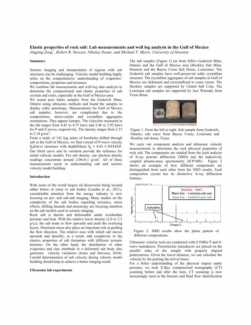
The salt samples (Figure 1) are from Sifto's Goderich Mine, Ontario and the Gulf of Mexico area (Hockley Salt Mine, Houston and the Bayou Corne Salt Dome, Louisiana). The Goderich salt samples have well-preserved cubic crystalline structure. The crystalline aggregates of salt samples in Gulf of Mexico are deformed and recrystallized to some extent. The Hockley samples are supported by United Salt Corp. The Louisiana salt samples are supported by Joel Warneke from Texas Brine.
We carry out component analysis and ultrasonic velocity measurements to determine the rock physical properties of rock salt. The components are studied from the joint analysis of X-ray powder diffraction (XRD) and the inductively coupled plasma-mass spectrometry (ICP-MS). Figure 2 shows an example of how different components are distinguished from each other from the XRD results. Each composition crystal has its distinctive X-ray diffraction features.
Ultrasonic velocity tests are conducted with 0.5MHz P and S-wave transducers. Piezoelectric transducers are placed on the parallel sides of the sample with properly aligned polarizations. Given the travel distance, we can calculate the velocity by the picking the arrival times. For a better understanding of the physical impact under pressure, we took X-Ray computerized tomography (CT) scanning before and after the tests. CT scanning is now increasingly used in the fracture and fluid flow identification
Figure 1. From the left to right: Salt sample from Goderich, Ontario, salt cores from Bayou Corne, Louisiana and Hockley salt dome, Texas.
Figure 2. XRD results show the phase pattern of different compositions.

Elastic properties of rock salt: Lab measurements and well log data analysis in the Gulf of Mexico
of rock. It clearly shows the density and micro fractures changing under pressure (Dustin and Grant, 2013).
1. Salt crystals, Goderich, Ontario
They are taken from the Stifto Salt Mine in Goderich, Ontario, Canada at the depth around 510-535m. The crystallographic orientation is clear and they come with slight external force-induced fractures. They are documented to be remarkably pure, containing less than 2% impurities (Hewitt, 1962). Our samples are tested to be almost pure halite (NaCl). The density measured at 24°C is around 2.15 g/cc. We observed the cubic anisotropy from them. Velocities are measured with waves propagating in two sets of directions: along the direction of symmetric axes and in the halfway between two symmetric axes (Table 1). The calculated elastic constants are: 𝐶!! = 48.7GPa , 𝐶!! = 13.1GPa , and 𝐶!" = 11.9GPa (Zong, 2014; Zong et al., 2014). Compared with the isotropic salt model, the travel time difference caused by such cubic anisotropy, from a numerical model, could up to 8%, 12% and 15% for P-wave, slow shear-wave and fast shear-wave, respectively. The computed 3D velocity distribution is given in Figure 3 (Zong, 2014).
2. Bayou Corne Salt Dome, Louisiana and the
Hockley Salt Mine, Texas
Samples L1 and L2 are cut from a 4-inch (101.60 mm) diameter salt core at the depth around 600 m of Bayou Corne Salt Dome, Louisiana. The visible granular crystal is irregular and has a size ranged from 3 to 20 mm. Generally, the volume
ratio of halite (NaCl) is around 95%. The rest is mainly anhydrite (CaSO4). Density is around 2.15g/ cm3. We measured the azimuthal velocities for L1 first in the room condition by keeping transducers standing and rotating L1 under 0° to 360° with a 10° increment. Rotation axis is the core axis. As we can see from Figure 4, both compressional and shear velocities vary with respect to polarization. L1 comes from the vertical well with less external force-induced fracture. The velocity variation (1.5% for Vp and 4% for Vs) in this case is most likely caused by the crystal alignment or heterogeneity. However, this type of anisotropy caused by elongate crystals is tested in a small diameter. It would not necessarily represent for the preferred orientation in this area.
For complementary measurements under pressure, we prepared a 1.5-inch diameter cylinder sample L2 for testing under tri-axial pressure 0 to 4000 psi. The CT scanning is conducted to understand the stress effects. The results are shown in Figure 5. Red line is the fitted trend of velocity measured during loading pressure while the aqua line is during unloading pressure. The Vp and Vs increase from 4.4
4.2
4.4
4.60
30
60
90
120
150180
210
240
270
300
330
4.2
4.4
4.6
Vp1 av
2.4
2.5
2.6
2.70
30
60
90
120
150180
210
240
270
300
330
2.4
2.5
2.6
2.7
Vs
1.60
1.65
1.70
0 10 2030
40
50
60
70
80
90
100
110
120
130
140150
160170180190200210
220
230
240
250
260
270
280
290
300
310
320330
340 350
1.60
1.65
1.70
1.75
Vp/Vs2
Figure 4. Azimuthal velocities of P- and S-waves in one cross section of L1. From left to right: P-wave velocity, S-wave velocity and Vp/Vs.
Table 1. Ultrasonic measurements for halite samples from Goderich salt mine, Ontario. Shear-wave splitting is observed
when wave propagates off the symmetric axes directions. φ
n
n
Figure 3. Phase and group velocities (km/s) distribution in space. The velocities are calculated based on the stiffness tensors from the Goderich salt samples.
Figure 5. Velocities of L2 under tri-axle pressure.

Elastic properties of rock salt: Lab measurements and well log data analysis in the Gulf of Mexico
to 4.8 km/s and 2.5 to 2.8 km/s, respectively. The CT scanning in Figure 6 shows the randomly distributed micro-cracks and fractures before loading pressure. The confining pressure closed almost all the micro-cracks, which is likely the main factor of the velocity rapidly increasing during first 1000 psi. The increment slows down with the further compression. While downloading pressure, the velocity will not go back to starting value due to the closure and annealing of micro-cracks under hydrostatic pressure.
Similar measurements under the room condition were carried out on the Hockley salt samples. They were taken from horizontal wells, around 460 m in depth. The crystalline aggregates are randomly distributed with the crystal size varying from several millimeters to 3 cm. The samples we tested contain over 98% halite (NaCl), around 1% anhydrite (CaSO4) and even less sylvine (KCl). Azimuthal velocities from different sections show no significant variance. Velocity and density of three sets of samples are listed in Table 2. Generally, cubic anisotropy would be expected in undeformed pure halite formation with well-preserved cubic crystals. However, slight velocity variation is observed in the Louisiana and Hockley salt cores. This is possibly due to their substantial deformation history.
Well logs in Gulf of Mexico We extend the study to 142 wells drilled through salt in the Gulf of Mexico. As the salt domes are widely distributed in the Gulf Coast, this study attempts to provide a general reference for velocity model building. Dr. Fred Hilterman and Geokinetics generously provided the well data. As shown in the Figure 7, the wells are located in the upper Gulf Coast, with the total coverage area around 93,600 km2. The study area covers the north side of Sigsbee salt canopy, the largest known salt structure. It is near the heart of U.S.
petrochemical industry and also one of the most developed oil and gas industries in the world.
Salt deposits are typically non-radioactive, non-porous, low density, high velocity, electrically nonconductive and soluble (Tixier and Alger, 1970). Figure 8 shows the logs in one well. Salt is highly recognizable and easily been delineated with high sonic velocity and extremely high resistivity.
1. Velocity versus depth
From the crossplot of velocity and depth (Figure 9), we find a trend of velocity increasing with depth. We fit such trend with a line:
𝑉! = 4.41 + 0.0145𝐷,
where 𝑉! is the P-wave velocity (km/s) and D is the depth (km). The average RMSE (root mean squared error) for this fit is 0.10 km/s. The salt rock normally contains small amount of impurities and other embedded evaporite minerals or clay.
Figure 8. Example logs from a borehole drilled through salt formation. Salt is marked with yellow color.
Figure 6. CT scanning shows the micro-cracks and fractures closed after tri-axial pressure tests.
Figure 7. Well locations. 142 well-logs supported by Dr. Fred Hilterman and the Geokinetics.
Table 2. The velocity and density measured in three sets of salt samples.

Elastic properties of rock salt: Lab measurements and well log data analysis in the Gulf of Mexico
The RMS error can give values for including velocity variations in ‘dirty salt’ model building. We tent to provide a realistic reference for salt velocity model in the Gulf of Mexico.
2. Velocity versus density
The electron density reading 𝜌! for salt is slightly lower than the actual bulk density 𝜌 . It can be corrected using the following equation:
𝜌 = 0.5 ∙𝐴𝑍∙ 𝜌!
where 𝐴 = 58.44 and 𝑍 = 28. So we generally have the relationship:
𝜌 = 1.044 ∙ 𝜌! Our electron density readings range from 1.98 to 2.16 g/ cm3 with most data concentrating around 2.06 g/cm3. We plot the electron velocity variation with density (Figure 10). The scattering on two ends (low and high density) is likely caused by some evaporates other than halite. Such as the common evaporites in Gulf of Mexico salt domes: sylvine, gypsum and anhydrite. Sylvine has lower density and velocity compared with halite. While anhydrite and gypsum have higher density and velocity. In the center of this cross plot, it is noticeable
that the velocity in halite varies a lot even at the same density. One of most possible scenario is the anisotropy. For the same salt formation, the preferred crystalline or fracture orientations would affect the sonic velocity readings along the borehole, but not the density. Conclusions In the lab, we test the composition, density, velocity and stress effects for different salt samples. In terms of the anisotropy, our samples show three different scenarios. We observed cubic anisotropy in the undeformed pure halite samples. The Louisiana salt cores show the slight velocity variation mainly due the alignment of deformed halite crystalline. The Hockley salt cores behave isotopically. The current results remind us that the isotropy assumption of salt formation should be considered during velocity model building. Compared with lab measurements, the field measurements provide an in-situ reference for building velocity models in specific environment with multiple influencing factors and other unknowns entailed (Gardner et al., 1974). We give an empirical relationship for velocity versus depth in Gulf of Mexico area from the log data analysis. Velocity increases slightly with depth. The density of rock salt does not show a clear relationship with velocity. These results are representative for general the Gulf of Mexico area. Through this study, we have a better understanding of salt properties and have provided values for salt velocity modeling for pre-salt and sub-salt imaging in the Gulf of Mexico area. Acknowledgement We would like to express our special thanks of gratitude to Dr. Fred Hilterman and the Geokinetics for the well-log data donation. We thank Joel Warneke, Texas Brine and United Salt Corp. for supporting the samples. We also thank Dr. James Korp, Dr. Yongjun Gao and Weihang Yang for the help during component analysis. Thanks to Yuandi Gan for a lot of intuitive discussions. We would like to thank all the Allied Geophysics Laboratory (AGL) personals for the technical and spiritual support.
Figure 9. Top: Cross-plot of velocity-depth data from the logs. Red line is the fitted curve. Bottom: The residual of our fit.
Figure 10. Cross-plot of log density and velocity for salt intervals.

Elastic properties of rock salt: Lab measurements and well log data analysis in the Gulf of Mexico
Dustin, C., and B. Grant, 2013, Experimental Examination of Fluid Flow in Fractured Carbon Storage Sealing Formations: International Journal of Geosciences, 2013.
Gardner, G., L. Gardner, and A. Gregory, 1974, Formation velocity and density-the diagnostic basics for stratigraphic traps: Geophysics, 39, 770-780.
Hewitt, D. F., 1962, Salt in Ontario: Dept. of Mines, Toronto Jones, I. F., and I. Davison, Year, Seismic imaging in and
around salt bodies: problems and pitfalls: 2014 SEG Annual Meeting, Society of Exploration Geophysicists.
Landrø, M., C. Puigdefabregas, and B. Arntsen, 2011, Anisotropy in the salt outcrop at Cardona, Catalonia–implications for seismic imaging: First Break, 29, 41-45.
Tixier, M., and R. Alger, 1970, Log evaluation of nonmetallic mineral deposits: Geophysics, 35, 124-142.
Zong, J., 2014, Elastic properties of salt: laboratory measurements, well-log analysis, and a seismic survey over the Hockley Salt Mine, Texas, University of Houston.
Zong, J., R. Stewart, and N. Dyaur, Year, Salt Anisotropy: Ultrasonic Lab Experiments and Traveltime Ramifications: 2014 SEG Annual Meeting, Society of Exploration Geophysicists.