el-2000 axsys access control system - kyodensha ...€¦ · 1 part i: introduction system...
TRANSCRIPT

EL-2000 AxSys Access Control System
- User Manual -

ii
Copyright Notice
Information in this document is subject to change without prior notice.
________________________ may make improvements or changes in this manual and
in the Access Control Application software at any time. The software, which includes the
information contained described in this document is furnished under a license
agreement and may be used or copied only in accordance with the terms of the
agreement. It is against the law to copy the software except as specifically allowed in
the license agreement. No part of this manual may be reproduced or transmitted in any
form or by any means, including photocopying and recording, for any purpose without
prior written permission of ___________________________..
iii
TABLE OF CONTENTS
Copyright Notice …………………………………………………………... ii
Trademark …………………………………………………………………... ii
Table of Contents ………………………………………………………….
iii
PART I Introduction …………………………………………............ 1 System Introduction …………………………………………………………. 1 About This Manual …………………………………………………………… 1
PART II Basic Configuration ……………………………………….. 2 Device Setup …………………………………………………………………. 2 Quick Start ……………………………………………………………………. 2
PART III Software Function …………………………………………. 4 File Menu ……………………………………………………………………… 5 Log In & Log Out ………………………………………………………. 5 Changing Password …………………………………………………… 6 System Setup ………………………………………………………………… 8 Comm Port ……………………………………………………………… 8 Properties ……………………………………………………………….. 9 System Info ……………………………………………………….. 9 Attendance Auto Posting & Export …………………………….. 10 Site Code Setting ………………………………………………… 11 Card Holder User Define Field …………………………………. 12 SMS & Email Setting ……………………………………………. 13 Notification ……………………………………………………….. 13 User Roles ……………………………………………………………… 14 User Account …………………………………………………………… 15 Panel Setting …………………………………………………………… 18 Site Definition ………………………………………………………….. 23 Database Setup ……………………………………………………………… 25 Time Set ………..………………………………………………………. 25 Time Zone …..….………………………………………………………. 27 Floor Zone ……………………………………………………………… 29 Access Roles …………………………………………………………... 31 Card User ………………………………………………………………. 33 Insert New Card …………………………………………………. 34 Parameters Modification ……………………………………...... 37 Edit Pin ……………………………………………………………. 38 Search Card Holder Record ……………………………………. 38

iv
Department Setting …………………………………………………… 40 Job Title Setting ……………………………………………………….. 42 Shift Setting ... ………………………………………………………….. 44 Holiday Set ……………………………………………………………... 46 Reporting ……………………………………………………………………... 48 Transaction Listing ……………………………………………………. 48 Time Attendance ………………………………………………………. 50 First IN / Last Out ……………………………………………………… 52 System Setting ………………………………………………………… 54 View Transaction ……………………………………………………… 56 User Tracking …………………………………………………………. 57 User Activation ………………………………………………………… 58 User Sign IN Without Out …..………………………………………… 60 Attendance Event …………………………………………………….. 61 System Operation …………………………………………………………… 63 Send Setting …………………………………………………………… 63 Retrieve Setting ……………………………………………………….. 64 Backup & Restore …………………………………………………….. 65 Reindex Database ……………………………………………………. 68 Load Report …………………………………………………………… 68
PART IV Hardware Function Configuration (Device Configuration Using Keypad) …..……………………….
71
Primary Settings & Defaults ………………………………………………... 71
Steps to Perform “Cold Start” ………………………………………… 71
Steps to Perform Quick Install ……………………………………….. 71
Manufacturer’s Default Settings ……………………………………... 71
Keypad’s Key Function ……………………………………………...... 71
Programming Menu 73
PART V Index …………………………………………………………. 84 System Connection Diagram ………………………………………………. 84 Device Intallation – Single Door Mode……………………………….. 84 Device Intallation – Dual Door Mode……………………………….. 85 Device Installation – Car Parking Mode ……………………………. 86 Device Installation – Lift Access Control System …………………… 87 System Datasheet ……………………………………………………………. 88 Definition and Description …………………………………………………… 89

v

1
PART I: INTRODUCTION System Introduction The Access Control System is a cost effective, powerful security device that monitors and controls the access to particular premises. Its complex design allows a single PC to control up to 128 of these devices, hence permitting control of 256 doors with one computer. It is also equipped with the function to control car park access and emergency access system. The package comes along with the Access Control Panel, which is the device itself, and the Access Control System Software. The device can be installed as a standalone component or linked to the PC, but both configurations are granted full access to the features provided by the device and runs at real time environment. This means that the device is able to store up to 10,000 access control transactions regardless whether the PC is turned ON/OFF, or even during power failure situation. Access Control Application Software is a powerful application tool with Windows Graphical User Interface (GUI) that provides user-friendly computer environment for parameters/data entry, transactions listing, user database configuration and storage, and report generation. This tool is able to support 8 PC communication buses/ports, with each port controlling 16 Access Control Panels, hence allowing the monitoring of 128 devices (256 doors) with only one control medium (your PC).
About This Manual In this manual, user will be guided with the step-to-step instructions of configuring and using this device and the software. A quick start session is being included for brief and basic setup of the system setting, allowing basic access control operation without fully utilizing the functionality provided. In the later chapter, Part III – Software Function, user will be guided through with detailed explanation of all the functions offered in the Access Control System. The configuration diagram and datasheets were included in the Index pages, along with the explanation of the technical terms and names that were used in this manual. Please refer to the index page for more information.

2
PART II: BASIC CONFIGURATION Device Setup This will setup the Access Control System device to your computer application.
1. Connect the device to the PC communication port with RS485 Converter port or RS232 Cabling Interface as indicated in the System Connection Diagram. Supported card formats included MiFi card format (used with MiFi readers ONLY), EM proximity 125 kHz, HID cards (used with HID readers ONLY), Rosslare all ranges. Supported readers are ABA-Track II, Wiegand format (26 bits, 32 bits, 34 bits, 35 bits, 37 bits), HID keypad, Rosslare keypad, Indala keypad, proximity 125 kHz, ABA Track 2 reader, LCD+Keypad,, finger print readers.
2. Launch Access Control System software, you’ll be asked to select a Comm Port via Comm Port Selection window. Select the appropriate Comm Port that is connected to your device.
3. The software will perform auto scanning on the device and configure it to its default setting.
4. If more than 1 device is connected to the same Comm Port, make sure that the physical address setting of the device is set differently.
5. Once the communication between the device and the software is being established, the LEDs (green and orange) on the device will start blinking; indicate the device is ready to be used.
6. The user can now perform any configuration on the AxSys Access Communication System according to their preference. Please refer to Panel Setting in PART III for details in device configuration
Quick Start This session only provides brief information on basic system setup, which only involves login/logout functions, communication port selection function, panel/device setting, and card holder registration function. NOTE: This session only touches the brief functions of the system, for more details please refer the following chapter – Part III Software Functions. To perform a quick start for the AxSys Access Control System, please refer to the following procedures:

3
1. Once the device is being set up, select login from the software’s main window to access into the program. Key in the default user name and password (user name and password are both the same by default): AxSys
2. System will prompt to select the appropriate PC comport. After select the comm. Port, please restart again the AxSys software. Then this software will automatically detect the attached control panel.
3. Once logged in, select System Setup from the side panel to bring down its menu. Select Panel Setting to setup the functionality of the access control device.
i. The system will prompt the user to an empty Panel Setting page, select “Insert” button to add in a new Panel Set.
ii. From the Edit Panel Setting window, type in the reference name for the setting under the Tag Name space. Provide some description if desired.
iii. Choose the access control type for the device under the Panel Type option box.
iv. The bus number is the representative number for the communication port that had been selected earlier on. Select the appropriate port from the Bus Number selection block.
v. Adjust the open time and release time (the time for the door to be remained open and the time for the lock to be released) of the device according to your preference.
vi. Select the reader type of the device from the Reader Type selection block. The rests of the parameters can be left as default setting.
vii. Select “OK” and the system will prompt the user to upload the settings onto the device. Select “Yes” to complete the setting process.
4. The user may register the card holders into the system’s database. Card registration can be easily done by:
i. From the main software page, select the “Capture Card” tab underneath the tool bar. A Capture Card window shall appear on the screen.
ii. Scan/flash the user card on the card reader, which is connected to the AxSys Access Control device.
iii. Select the “Execute” tab and the system will prompt the user to confirm the card registration procedure. Select “Yes” and the system will add the new card information into the database.
NOTE: You may flash all the user cards you desired before proceeding to step (iii). The system will add in all the user cards at once.
The user may now use the device’s basic functions for simple access control operations.
4
PART III: SOFTWARE FUNCTION
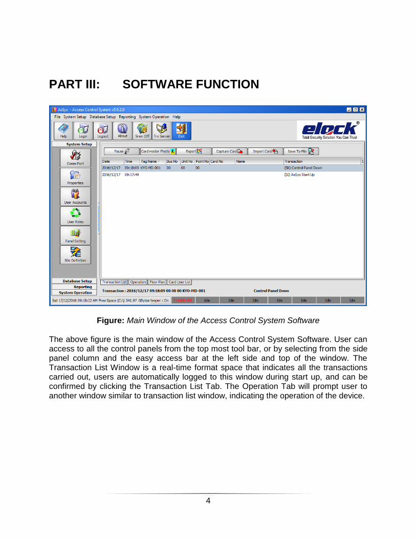
Figure: Main Window of the Access Control System Software The above figure is the main window of the Access Control System Software. User can access to all the control panels from the top most tool bar, or by selecting from the side panel column and the easy access bar at the left side and top of the window. The Transaction List Window is a real-time format space that indicates all the transactions carried out, users are automatically logged to this window during start up, and can be confirmed by clicking the Transaction List Tab. The Operation Tab will prompt user to another window similar to transaction list window, indicating the operation of the device.

5
File Menu File Menu is the first menu on the tool bar. The functions included the Log In and Log Out functions, password changing function and the exit function. These functions were all listed on the easy access bar as being indicated in the previous figure. Log In & Log Out
1. Click on the Login icon from the easy access bar or from the File Menu from tool bar to access the software. User will be prompt to the following window.
2. Key-in the user ID and password to log in. The default user ID and password are the same: AxSys .
Figure: System Log In Form User can create new login ID and password from the User Account option under the System Setup menu. The ID will be indicated at the center bottom of the screen after logged in. NOTE: Maximum word length for user ID is 12 characters size Maximum word length for password is 15 characters size. (Default: ID: AxSys, Password: AxSys)

6
Figure: System Log Out/Exit Form The user may log out of the software by:
1. Click on the Logout icon from the easy access bar or from the File Menu option from tool bar. The above window will pop out.
2. Key in the password to log out they system. Be reminded that the system is not turned off and is still connected to the device in this condition. To disconnect the software from the device and exit the system:
1. Click on the Exit button on the easy access bar or on the Close option from the File menu.
2. The software will prompt you to turn off the application, click “Yes”. 3. Above window will pop out, key in the password to exit the system.
Changing Password The user password can be changed by any software users who logged into the system. The following instructions are the steps to change password.
1. The user must log into the software beforehand. 2. Click on the File Menu to bring down the action options, click on the Change
Password option. 3. A window asking for old password will appear, key-in the old password (current
password) for verification.
Figure: Enter Old Password

7
4. Then a new window will pop out, key in the new password.
Figure: Enter New Password
5. Key-in the new password again for verification. Hit <Enter> or click on the “OK”
button on the Change User Password window.
Figure: Re-enter New Password for Verification
6. Exit the system using the old password. 7. Log in again with the new password to activate the password and to complete the
steps.

8
System Setup Comm Port Communication Port, or Comm Port for short, is the connection port for data transaction between the computer software and the access control device. The AxSys Access Control System software is designed to be able to interface with 4 Comm Ports as total, hence this option allows the user to link/allocate the appropriate port to the software’s interface. It can be easily done by:
1. Make sure the computer is connected to the device with a communication cable. 2. Select System Setup menu from tool bar or from the side panel, then select
Comm Port option. 3. A window as being shown in the figure below can be seen. Click on the down
arrow button to select the appropriate port that had been used to link with the software’s buses.
Figure: Comm Port Selection Window Figure: Selecting the Comm
4. Click “OK” to complete the selection. If the wrong port is being selected, the system will prompt the user with an error message.

9
Properties This option allows the user to specify the company information, time attendance posting properties, site/area security code, and card holder’s predefined data fields. To make changes on these properties, select System Setup menu from the tool bar or from the side panel, then select Properties option. System Info This property is to specify the company information that the user would prefer to be generated on their reports or their system. The information that can be displayed includes the company name and the company logo.
Figure: System Info Page
This System Info page is the default page that user would see every time the Properties option is being selected. Key-in the company name on the field provided. The user is allowed to upload their company logo into the system to be generated on their reports. But the logo size must be 100×100 pixels, saved as .BMP file. Just click on the “Capture” button to search for your company logo, double click on the picture and the logo will be displayed on the Report Logo field. Click “Change” and the information will be saved. However, the application will not take effect immediately. Please exit the system and log in again for the changes to take effect. The user should be able to view their company name displayed at the top of the software

10
Attendance Auto Posting & Export This function is being used for attendance filtering and data documentation purposes. Enabling this mode will allow the system to automatically update the attendance report in a set period of time, automatically rearrange the attendance report documents in the system. To set up this feature, click on the Attendance Auto Posting & Export tab on the System Properties window.
Figure: Attendance Auto Posting & Export Page
Enabling the Auto Purging function will allow the system to automatically erase the old time attendance transaction files in the specified time line.
The Auto Export function will export the time attendance report into the system’s root directory, the expfolder (C:\Program Files\Access Control System\ExpFolder).
The report will be kept for a set period of time before it is deleted from the system, and the time period can be set from the “Month(s) to Keep” option tab.
The Auto Posting feature allows the system to automatically generate the time attendance transaction files in a set period of time. This will properly organize the time attendance documents and ease up the report generation procedure when desired.
Over Time Rest Time Setting allows the system to calculate the over time more accurately by deducting the specified the rest time.
Work Hour / OT Setting allows system to automatically align the OT hour to quarterly and also allow total work hour to deduct with break hour time. (Break hour time is specified in Shift Setting)

11
Site Code Setting The Access Control System allows the user to create 10 different security codes for different premises, hence named as Site Codes. Meaning different areas can be set with different security code. If the user does not set any site codes in the software, there would be no security protection against unknown card entry into the premises. To setup Site Code, click on the Site Code Setting tab on the System Properties window, your page should change to this form:
Figure: Site Code Setting Page
“0000” indicates no code has been set. Highlight the “0000” field and enter a 4 digits number to set the site code. Hit “Change” to confirm the changes that had been made.
12
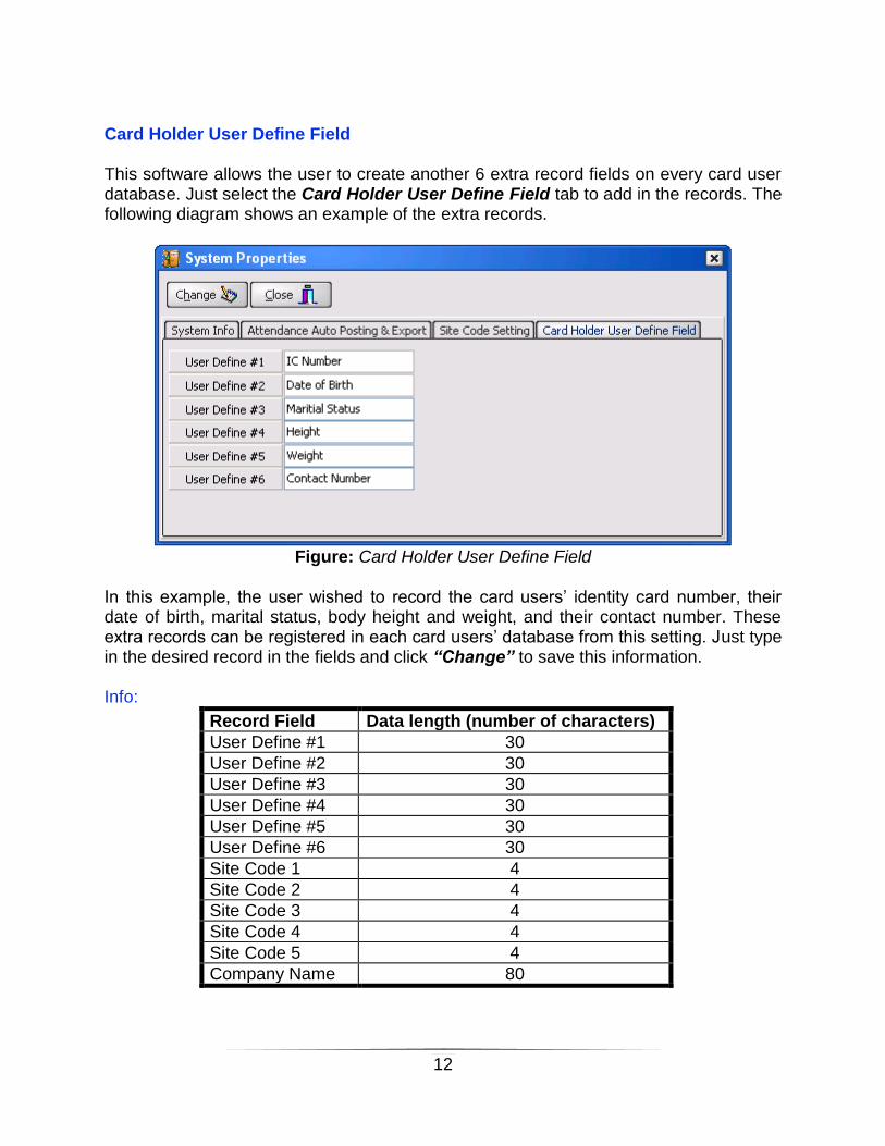
Card Holder User Define Field This software allows the user to create another 6 extra record fields on every card user database. Just select the Card Holder User Define Field tab to add in the records. The following diagram shows an example of the extra records.
Figure: Card Holder User Define Field
In this example, the user wished to record the card users’ identity card number, their date of birth, marital status, body height and weight, and their contact number. These extra records can be registered in each card users’ database from this setting. Just type in the desired record in the fields and click “Change” to save this information. Info:
Record Field Data length (number of characters)
User Define #1 30
User Define #2 30
User Define #3 30
User Define #4 30
User Define #5 30
User Define #6 30
Site Code 1 4
Site Code 2 4
Site Code 3 4
Site Code 4 4
Site Code 5 4
Company Name 80

13
SMS & Email Setting This setting allows user to specify the email or SMS account in order for AxSys software send out alert or time attendance report email to specified email account.
Figure: SMS & Email Setting Page
Notification Setting This features is used for user to specify attendance reporting late in checking time, Card Expiry checking time and system error indication email receiver address. Mean, AxSys will automatically send out notification via email based on the specified checking time and email account .
Figure: Notification Setting Page

14
User Roles This setting gives the administrator the options to create restriction access for different users who logged into the software. Click the System Setup menu to bring down the option lists from the tool bar, or from the side panel. Click User Roles to bring up the setting page.
Figure: User Roles Setting Page
Steps to Create New User Roles:
1. To create new user roles, click on the “Insert” button. 2. Choose the menu access number (ranging from 1 to 99). 3. Select the access options that you wished to grant for the others by clicking the
selection box shown beside each setting options. The user may switch to other menu (System Setup, Database Setup, Reporting, and System Operation) by clicking on the menu tab listed on the window.
4. Selecting/Enabling the View Card PIN No. will enable the login user to view every user’s password.
5. Select “save” to store the setting into database. User may also choose to edit the existing User Roles by selecting the “Modify” button to make the changes.

15
User Account This menu is used to create new user ID and password to access this software. The password for the new user ID is set to be the same by default; it can be changed later by the user themselves. To create a new user account:
1. Select System Setup menu from the tool bar or from the side panel, then select User Account option. The following window will appear.
Figure: User Account Window

16
2. Click “Insert” to add a new user ID into the system. The following window will
pop out.
Figure: Add User Account Form
3. Fill in the ID and the name in the provided space.
NOTE: Password is set to be the same as the User ID by default.
4. Select the User Type for the new account, whether to be an admin, which will be granted access to System Setup; or a normal account, which user cannot access to System Setup option.
5. Select the User Roles granted for this new account. Click the “00” tab to bring up
the User Roles window. Click the next and previous buttons ( ) to select the User Roles that you wish to grant for the new user. Click on the “Select” tab to confirm the User Roles. NOTE: To create a new User Roles setting, please refer to the User Roles chapter from previous.

17
6. Select “OK” to confirm the new user account. A reminder window will pop out to
indicate that user password is set to be the same as user ID by default. Click “OK” to complete the new user registration.
Figure: Sample User Accounts
After completing the user accounts, click the “Close” tab to exit the setting. You may also choose to delete any of the user accounts as desired.

18
Panel Setting This option is used to configure the system control panel settings. Or in other word, it is used to control the access system for different doors. To access into this option, click System Setup menu from the tool bar or from the side panel. Click Panel Setting to view the available panels in the system or to add a new panel setting to the database.
Figure: Panel Setting Window
To add a new panel setting into database, click “Insert” to bring out the Edit Panel Setting window. To edit an available panel setting in the database, select the panel that you wished to modify then click the “Modify” button to bring out the Edit Panel Setting window and begin modification. Or, the user may double click on the panel to perform modification.

19
Figure: Edit Panel Setting Window
The parameters of the panel setting are explained in the following table.
Parameters Description
Tag Name Panel/device name that will be displayed on the log file.
Description Short explanation of the panel.
Panel Type This indicates the operation type of the device, which included: 1. Single door – In/Out Reader 2. Double door – 2 In Reader 3. 1-IN/1-OUT Barrier 4. Emergency Door 5. Time Attendance Panel

20
6. 2-IN/2-OUT Barrier 7. Alarm Monitoring Panel 8. Single Door – i4Flexi-W 9. Single Door – S903-B 10. Double Door – S903-B 11. Single Door – S904-B 12. Double Door – S904-B 13. Lift Access Panel
Bus No. PC communication port to the device/panel.
Unit No. The device’s physical address. Ranging from 0 to 15.
Release Time Time period (second) for the lock to be released. Once exceeding the limit, the system will automatically lock back the door and produce a warning signal/sound.
Open Time Time period (second) for the door to be remained open. Once exceeding the period, the system will generate warning signal/sound.
Security Mode Setting the security level for the device. There are two security level for configuration: HIGH = System will NOT permit entrance or exit if card error is detected. LOW = System will allow card entrance/exit even there is card error checking condition
Site Type This option allows the user to select the networking system used for the device to communicate with the software. Select Local site type under normal application. User may be required to create and select a new site type for long distance monitoring purposes. NOTE: Please refer to the Site Definition sub-chapter under System Setup.
Suspend Polling This will enable/disable polling for the device. Enabling polling will allow the software system to wait and monitor the device until the device is ready to be read.
Access Limits Number of time a person can access to the premises. “0” indicates no access limits.
Antipassback Reset Time
The antipassback is to prevent double entry of the same card on the same premises without exiting the facility beforehand. After the antipassback is triggered, this setting will allocate a time period before the system is being reset/refresh back to its initial status. Time 00:00 will disable the reset function. Only available in Single Door, 1-IN/1-OUT Barrier, and Time Attendance Panel.
21
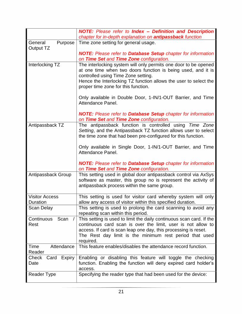
NOTE: Please refer to Index – Definition and Description chapter for in-depth explanation on antipassback function
General Purpose Output TZ
Time zone setting for general usage. NOTE: Please refer to Database Setup chapter for information on Time Set and Time Zone configuration.
Interlocking TZ The interlocking system will only permits one door to be opened at one time when two doors function is being used, and it is controlled using Time Zone setting. Hence the Interlocking TZ function allows the user to select the proper time zone for this function. Only available in Double Door, 1-IN/1-OUT Barrier, and Time Attendance Panel. NOTE: Please refer to Database Setup chapter for information on Time Set and Time Zone configuration.
Antipassback TZ The antipassback function is controlled using Time Zone Setting, and the Antipassback TZ function allows user to select the time zone that had been pre-configured for this function. Only available in Single Door, 1-IN/1-OUT Barrier, and Time Attendance Panel. NOTE: Please refer to Database Setup chapter for information on Time Set and Time Zone configuration.
Antipassback Group This setting used in global door antipassback control via AxSys software as master, this group no is represent the activity of antipassback process within the same group.
Visitor Access Duration
This setting is used for visitor card whereby system will only allow any access of visitor within this specified duration.
Scan Delay This setting is used to prolong the card scanning to avoid any repeating scan within this period.
Continuous Scan / Rest
This setting is used to limit the daily continuous scan card. If the continuous card scan is over the limit, user is not allow to access. If card is scan leap one day, this processing is reset. The Rest day limit is the minimum rest period that used required.
Time Attendance Reader
This feature enables/disables the attendance record function.
Check Card Expiry Date
Enabling or disabling this feature will toggle the checking function. Enabling the function will deny expired card holder’s access.
Reader Type Specifying the reader type that had been used for the device:

22
1. ABA Track 2 2. Weigand Format (26bits, 32bits, 34bits, 35bits, 37bits) 3. HID Keypad (only for HID brand RFID readers) 4. Rosslare Keypad 5. Indala Keypad 6. User Define Wieagand 7. Card/Key Format 8. LCD + Keypad 9. Adalo Reader
Name The tag name for the device will be automatically updated to this field once the setting is completed.
Lock Release TZ Time-zone to activate or deactivate the lock release period limitation system.
Push Button TZ Time-zone to activate or deactivate the push button function, which is used to release the locking system with just a push button.
Card + Pin TZ Time-zone to activate or deactivate the card and pin access feature. The feature can only be used with keypad integration.
Buddy Mode TZ Time-zone to activate or deactivate buddy mode feature. Buddy Mode feature is a high security procedure mode that requires 2 valid cards to be presented to the device to gain access.
Release on Fire Alarm Event
Enabling this feature will release the door lock when fire alarm event is detected, regardless of the time-zone setting.
Siren TZ Set Time zone to trigger siren/notification alarm.
Input Point Setting An option tab that is only available in Emergency Door mode and Alarm Monitoring Panel.

23
Site Definition The Site Definition feature is used for long distance monitoring purposes, as a remote for the AxSys Access Control System device using the Ethernet as the communication medium. To create a new site definition:
1. From System Setup menu, select Site Definition to access into the following main window. Select “Insert” to create new site.
Figure: Site Definition Main Window
Figure: Edit Site Record Window

24
2. Enter the name for the new definition in the Site Code field; provide some description for the new setting.
3. Key in the IP address of the monitoring computer (i.e. your PC) in the IP Address field.
4. User may enter a Host Name is domain network. 5. Select the “OK” tab to complete the new site registration procedure.

25
Database Setup Time Set The time interval set is an option to activate or deactivate the access control features on particular time frame for one particular day. It is the primary time block description before entering Time Zone database setting. The setting describes the time frames for ONE day operation, each day is provided with the option to allocate three time frames. To add in a new time set or to view/modify the available time set, click on the Database Setup menu from the tool bar, or from the side panel to bring down the options, click on the Time Interval Set option to open the window as shown in the figure below.
Figure: Time Interval Set Window

26
The two time sets (Time Set “000” and Time Set “001”) are the default time sets created by the manufacturer that cannot be deleted nor modified. Time Set “000” indicates no access setting, meaning that there would be no access to the premises at all time if this setting were chose, whilst Time Set “001” allows access at all time (24 hours). Follow the instructions below to add in a new time set:
1. Click “Insert” to open Edit Time Set Record window shown in the following diagram.
Figure: Edit Time Set Record Window
2. Choose the appropriate time set number from the “Time Set No.” space. Type in
some descriptions to note down the time set function. 3. Set the time frame by clicking the up and down arrow or by keying-in the digit in
the first interval frame (Interval 1). The “Hour” column ranged from 0 to 23 at max. The “Minute” column ranged from 0 to 59.
4. Set the time frame beginning with Interval 1, the other two can be left alone if it is unnecessary.
5. Click the “OK” button to confirm the setting. To modify an existing setting, just select the desired time set, click “Modify” tab from the Time Interval Set window and begin modification. Info: Only 255 time interval sets can be created for this system.

27
Time Zone Set This setting is used to activate or deactivate the system features for one week time frame. It is made up of 8 sets of Time Interval Sets, each representing one day of the week with an extra row representing the holiday that might be available in a particular week. The following figure indicates the Time Zone Set window that will appear once accessed into this setting option.
Figure: Time Zone Set Window
This window can be activated by selecting Database Setup menu to bring out the options from the tool bar or from the side panel, select Time Zone Set to access into the setup page.

28
Same as the Time Interval Set, there are two default settings available in the database that cannot be deleted nor modified. The TZ “000” indicates no access granted at all time; TZ “001” indicates the opposite. The user may add in new time zones by selecting the “Insert” button. The following window can be seen on the screen.
Figure: Edit Time Zone Record Window
To set the time zone:
1. Click on the down arrow button to view the time interval set available. 2. Select the time interval set that you desired for the day. Repeat the selection
procedure for other days. 3. Click “OK” once completed the new time zone insertion.
Modification of the existing time zone can be done by selecting the time zone and click “Modify” button to begin modification.

29
Floor Zone This setting is used to specify the Lift Access Floor Selection roles. Each floor zone have maximum 6 interval group. Each group is represent the Lift Relay ID in Relay module. If user is using this Floor Zone, the specified rely ID will trigger. The relay triggering time is configured in panel setting under release time column. The maximum relay ID is limited to 64 which represent the total floor controller under single Lift Access Panel.
Figure: Floor Zone Window

30
In order to configure the floor zone setting, user simply click on insert button, system will appear following menu, just choose the desired floor zone no and select the group relay ID. Press OK to save the setting.
Figure: Floor Zone Window
This floor zone setting will later used in Access Role setting whereby user allow to configure the floor zone no in Lift Access System. Just click and specify the floor zone in Floor Zone column.
Figure: Floor Zone Setting in Access Role Window

31
Access Roles An Access Role is a set of time zone records for a particular device. The system will check for the card validity at a particular time zone by comparing the current time with the recorded time zone sets. Unmatched time zone sets will deny the card holder’s access into the premises. Click on the Database Setup tab from the tool bar or the side panel to bring down the menu, select Access Roles to view the settings for the devices.
Figure: Access Roles Main Window
32
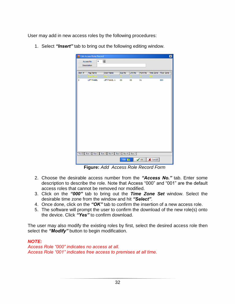
User may add in new access roles by the following procedures:
1. Select “Insert” tab to bring out the following editing window.
Figure: Add Access Role Record Form
2. Choose the desirable access number from the “Access No.” tab. Enter some
description to describe the role. Note that Access “000” and “001” are the default access roles that cannot be removed nor modified.
3. Click on the “000” tab to bring out the Time Zone Set window. Select the desirable time zone from the window and hit “Select”.
4. Once done, click on the “OK” tab to confirm the insertion of a new access role. 5. The software will prompt the user to confirm the download of the new role(s) onto
the device. Click “Yes” to confirm download. The user may also modify the existing roles by first, select the desired access role then select the “Modify” button to begin modification. NOTE: Access Role “000” indicates no access at all. Access Role “001” indicates free access to premises at all time.

33
Card Holder This option allows the system to register the card holder’s information into the database. To view the card holders’ data, select Database Setup tab from tool bar or side panel to bring down the menu, select Card Holder option to open up the Card Holder page as indicated in the following figure.
Figure: Card Holder Database
The database contains a space to list down all the card holders, the card information, and the card’s last scanned location data. The user may set another six information fields on the User Define Fields section to record the card holder’s data. NOTE: Please refer back to Properties under System Setup chapter for information on User Define Fields setting.
34
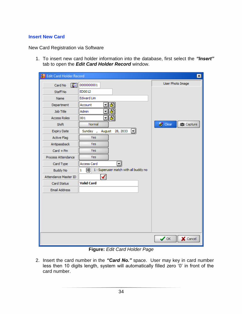
Insert New Card New Card Registration via Software
1. To insert new card holder information into the database, first select the “Insert” tab to open the Edit Card Holder Record window.
Figure: Edit Card Holder Page
2. Insert the card number in the “Card No.” space. User may key in card number
less then 10 digits length, system will automatically filled zero ‘0’ in front of the card number.
35
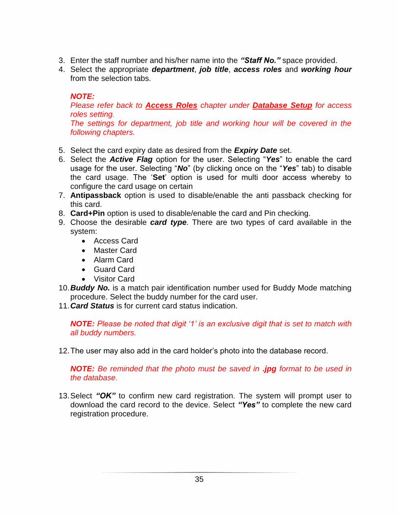
3. Enter the staff number and his/her name into the “Staff No.” space provided. 4. Select the appropriate department, job title, access roles and working hour
from the selection tabs. NOTE: Please refer back to Access Roles chapter under Database Setup for access roles setting. The settings for department, job title and working hour will be covered in the following chapters.
5. Select the card expiry date as desired from the Expiry Date set. 6. Select the Active Flag option for the user. Selecting “Yes” to enable the card
usage for the user. Selecting “No” (by clicking once on the “Yes” tab) to disable the card usage. The ‘Set’ option is used for multi door access whereby to configure the card usage on certain
7. Antipassback option is used to disable/enable the anti passback checking for this card.
8. Card+Pin option is used to disable/enable the card and Pin checking. 9. Choose the desirable card type. There are two types of card available in the
system:
Access Card
Master Card
Alarm Card
Guard Card
Visitor Card 10. Buddy No. is a match pair identification number used for Buddy Mode matching
procedure. Select the buddy number for the card user. 11. Card Status is for current card status indication.
NOTE: Please be noted that digit ‘1’ is an exclusive digit that is set to match with all buddy numbers.
12. The user may also add in the card holder’s photo into the database record. NOTE: Be reminded that the photo must be saved in .jpg format to be used in the database.
13. Select “OK” to confirm new card registration. The system will prompt user to download the card record to the device. Select “Yes” to complete the new card registration procedure.

36
New Card Registration via Card Scanning Procedure
1. For card registration via card scanning procedure, please ensure that the device is connected to a card reader.
2. User is not required to open any option pages. Just log in to the system will do. Noticed that from the software’s main menu, a “Capture Card” option is available under the tool bar:
Figure: System Main Page – “Capture Card” Option Tab Indication
3. Click on the “Capture Card” option to bring out the card capture window indicated in the following figure:
Figure: Capture Card Window

37
4. Scan/flash the new user card on the card reader. 5. Select the “Execute” tab and the system will prompt the user to confirm the card
registration procedure. Select “Yes” to add the new card information into the database.
NOTE: You may flash all the user cards you desired before proceeding to step (5). The system will add in all the user cards at once. Parameters Modification The AxSys Access Control System provides option to edit and even group edit the card holders’ database. The group edit option allows the user to edit and synchronize the parameters of several card holders with one selection. To Modify a Single Card Holder’s Settings:
1. Select the card holder that you wished to modify from the Card Holder Database window.
2. Select the “Modify” tab to bring out the Edit Card Holder Record page and begin modification.
To Modify a Group of Card Holders’ Settings:
1. Select the “Group Edit” tab from the Card Holder Database window. A Group Edit window will appear as shown in the following figure:
Figure: Group Edit Window (sample)
38
2. From the Group Edit window, select the Parameters option that you wish to modify from the parameters option tabs.
3. Select the card holders that you wish to modify from the card selection screen. Just click on the empty box in front of the card number. Once selected, you will see a tick in the box. To deselect the card, just simply click on the ticked box again.
4. Begin modification by selecting the parameters available in the parameters box. Noticed that there is a “Current” setting and a “Change to” setting in every parameter options. The “Current” setting may be ignored as it does not contribute to any changes to the parameters.
5. To modify the parameters, select the “Change to” setting tab, and change the parameter as desired.
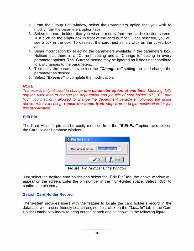
6. Select “Execute” to complete the modification. NOTE: The user is only allowed to change one parameter option at one time. Meaning, let’s say the user wish to change the department and job title of card holder “01”, “02” and “03”, you may only allowed to change the department parameter following the guide above. After executing, repeat the steps from step one to begin modification for job title modification. Edit Pin The Card Holder’s pin can be easily modified from the “Edit Pin” option available on the Card Holder Database window.
Figure: Pin Number Entry Window
Just select the desired card holder and select the “Edit Pin” tab, the above window will appear on the screen. Enter the pin number in the high-lighted space. Select “OK” to confirm the pin entry. Search Card Holder Record The system provides users with the feature to locate the card holder’s record in the database with a user-friendly search engine. Just click on the “Locate” tab in the Card Holder Database window to bring out the search engine shown in the following figure.

39
Figure: Search Card Holder Record (Search Engine)
User may choose to search by card number or by name or by staff code. Select the search preference and key-in the code/name in the space provided. Hit “OK” to initiate the search.

40
Department Setting The user can input the department name and descriptions into the database to be applied on the card holder database report. To initiate the department settings, select the Database Setup tab from the tool bar or the side panel to bring down the menu. Select Department Setting to begin configuration.
Figure: Department Setting Window
From the Department Setting window, user may insert new departments into the database by selecting the “Insert” tab to bring out the Add Department Record window shown in the following figure:

41
Figure: Add Department Record
Enter the Tag Name, which is the department name into the space provided. Include some descriptions to describe the department. User is allow to key in the email receiver account and Hand Phone number if required to have email message alert on every card scan. Select “OK” to add the record into the database. To modify the existing department, select the department name and click “Modify” to begin modification. Be noted that the Tag Name cannot be modified; only the Description can be changed in the setting. Info: Tag Name – 12 characters length Description – 30 characters length

42
Job Title Setting This setting allows the user to create a job description record that will be implemented into the card holder database report. To set the job title, select Database Setup from tool bar or side panel to bring down the menu, select Job Title Setting option to access into the setting page.
Figure: Job Title Setting Window
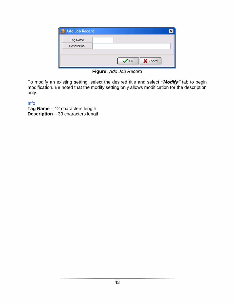
The user may add in new job title into the database by clicking the “Insert” tab. From the Add Job Record window, enter the job title into the Tag Name space and provide some description for the title. Click “OK” to confirm the setting and update into the database.
43
Figure: Add Job Record
To modify an existing setting, select the desired title and select “Modify” tab to begin modification. Be noted that the modify setting only allows modification for the description only. Info: Tag Name – 12 characters length Description – 30 characters length

44
Shift Setting The user may specify the company’s working time table and shift data with the aid of the Working Hour Setting. The data is used for time attendance calculation and as a reference for other settings. To access into this setting page, select Database Setup from tool bar or the side panel to bring down the menu, select Shift to open up the listing page shown in the following diagram:
Figure: Working Hour Setting Page
45
The user may insert a working hour setting into the database by:
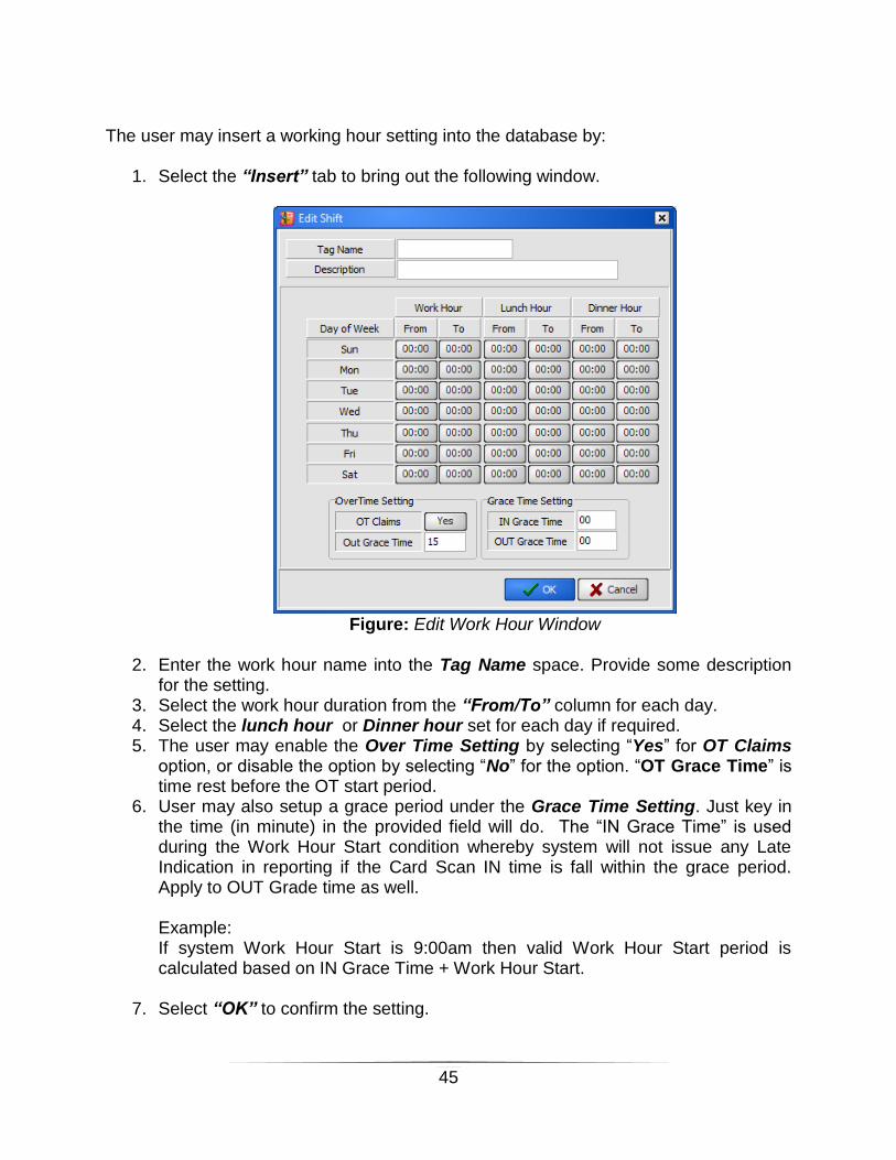
1. Select the “Insert” tab to bring out the following window.
Figure: Edit Work Hour Window
2. Enter the work hour name into the Tag Name space. Provide some description
for the setting. 3. Select the work hour duration from the “From/To” column for each day. 4. Select the lunch hour or Dinner hour set for each day if required. 5. The user may enable the Over Time Setting by selecting “Yes” for OT Claims
option, or disable the option by selecting “No” for the option. “OT Grace Time” is time rest before the OT start period.
6. User may also setup a grace period under the Grace Time Setting. Just key in the time (in minute) in the provided field will do. The “IN Grace Time” is used during the Work Hour Start condition whereby system will not issue any Late Indication in reporting if the Card Scan IN time is fall within the grace period. Apply to OUT Grade time as well. Example: If system Work Hour Start is 9:00am then valid Work Hour Start period is calculated based on IN Grace Time + Work Hour Start.
7. Select “OK” to confirm the setting.

46
Holiday Set The Holiday Set is being used as part of the time zone setting, providing calculation for system operating time zone by taking into the consideration of holidays that may occur in the mean time. To access into the Holiday Set option, Select Database Setup option from the tool bar or the side panel to bring down the menu. Select Holiday Set to begin configuration.
Figure: Holiday Set Window
The system provides 60 slots for holidays edit. Just click on one of the empty slots to begin configuration, or click on the existing slots to begin modification.

47
Figure: Edit Holiday Window (Modification Window)
Select the desired day and month in the provided slots. Enter some description to define the holiday set. Select “OK” to confirm the setup. Click “Clear” to erase the selected existing set. Once completed the setups, select “Close” to exit the setup system.

48
Reporting The Access Control System allows different report generating, previewing, and printing for different functions such as the transaction listing, the transaction files, system setting report, and also the card holders’ time attendance report.
Transaction Listing The Transaction Log records all the activities gone through the software, and the user can preview the log report and even filter out the unwanted records in the report, preparing the report for printing and back up purposes. To view this report, click on the Reporting tab from the tool bar or from the side panel to bring down the menu. Select Transaction Listing to bring out the Transaction Log File Lister window.
Figure: Transaction Log File Lister Window
1. Select the transaction date that you wish to view from the Transaction Date
Selection box. 2. Select the time zone desired for the report from the Time box. 3. The user is given the option to filter out the unwanted records from the report.
The options provided are:

49
Card Number Filter – to select only the card number that you wished to view.
Staff Number Filter – selection by staff number.
Department Filter – selecting the department that you wished to view.
Job Title Filter – selection by job title.
Control Panel Filter – view report for particular device only.
Event Filter – selecting particular event/action recorded to view. Note: Select “Ignore” to disregard the filtering.
4. Select the report sorting order from the Sort Order box and hit “OK” to preview
the report.
5. From the preview page (Print Preview), select the Print Icon ( ) to print out the report as back up purposes.
Note: Please ensure the PC is loaded with valid printer driver before this reporting. System will shutdown immediately is invalid printer driver detected.

50
Time Attendance The Time Attendance function summarizes the card holder’s daily and monthly attendance into report format. NOTE: Please make sure that the Working Hour setting for each card holders are properly defined in the Card Holder Database before generating a time attendance report. To view the Time Attendance report:
1. From the Reporting menu, select Time Attendance tab to open up the Report Selection window.
Figure: Report Selection Window
2. There are 12 different attendance report listings available for user’s selection.
Just click on the preferred option to view the report.
3. The user shall be prompted to the filtering window where the user can select the type of filtering for the report.

51
The following diagram shows a filtering window for the Attendance Summary Listing report:
Figure: Filtering Window Sample – Attendance Summary Report
4. After selecting the filtering method and the Sort Order for the report, select the
“Preview” tab to view the report. The following figure shows the report sample of the Attendance Summary Listing:
Figure: Time Attendance Report Sample – Attendance Summary Listing

52
First IN / Last Out This function is summaries all the user attendance based on selected date and separated it accordingly to First In, Last out, lunch OUT, Lunch IN, Dinner OUT & Dinner IN. System you may allow to filter certain card user for attendance record. The “Rebuild FILO” option is used to regenerate again the time attendance record. NOTE: User is not allows to regenerate (Rebuild) current date attendance.
Figure: First IN / Last OUT Window

53
Figure: Sample First IN / Last OUTReport
54
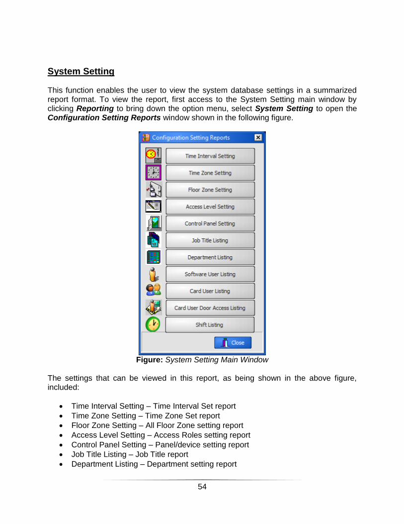
System Setting This function enables the user to view the system database settings in a summarized report format. To view the report, first access to the System Setting main window by clicking Reporting to bring down the option menu, select System Setting to open the Configuration Setting Reports window shown in the following figure.
Figure: System Setting Main Window
The settings that can be viewed in this report, as being shown in the above figure, included:
Time Interval Setting – Time Interval Set report
Time Zone Setting – Time Zone Set report
Floor Zone Setting – All Floor Zone setting report
Access Level Setting – Access Roles setting report
Control Panel Setting – Panel/device setting report
Job Title Listing – Job Title report
Department Listing – Department setting report
55
Software User Listing – software users report
Card User Listing – card holders’ report
Card User Door Access Listing – Listed out user accordingly to access role.
Shift Listing – Show all the shift setting in the system For example to view the report, just click on the desired options will do. However, the system provides filtering options for Card Holder Listing report. To view the Card User Listing report:
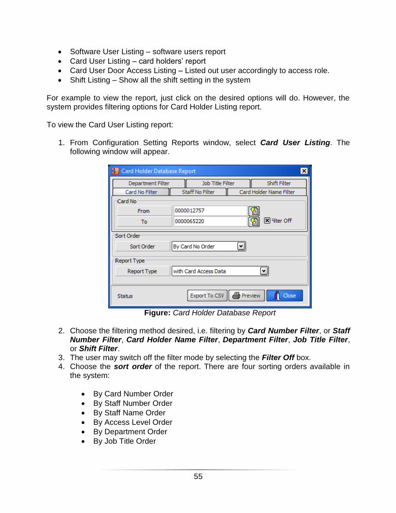
1. From Configuration Setting Reports window, select Card User Listing. The following window will appear.
Figure: Card Holder Database Report
2. Choose the filtering method desired, i.e. filtering by Card Number Filter, or Staff
Number Filter, Card Holder Name Filter, Department Filter, Job Title Filter, or Shift Filter.
3. The user may switch off the filter mode by selecting the Filter Off box. 4. Choose the sort order of the report. There are four sorting orders available in
the system:
By Card Number Order
By Staff Number Order
By Staff Name Order
By Access Level Order
By Department Order
By Job Title Order

56
5. Select the report format from the Report Type option. The user may select to view the report with the card access data or with the user defined data.
6. Select the “Preview” tab to view the report.
View Transaction The View Transaction function provides the user with the capability to retrieve the past event log files for viewing purposes. To access into this function, select Reporting option from the tool bar or from the side panel to bring down the menu, select View Transaction option to open up the Log File Viewer window as indicated by the following figure.
Figure: Log File Viewer Window To view a file:
1. Select the log event date. User may also perform card number filtering. 2. Select the file that you wish to view, select the “Open This Transaction Log
File” to view the log at the bottom space of the Log File Viewer window.

57
User Tracking This function allow system user to perform card user current access location tracking. Just select the date and perform filtering if required. Press OK or “Export To CSV” to generate the tracking report. The report will indication the last accessing time of card user.
Figure: User Tracking Window
Figure: Sample User Tracking Report

58
User Activation This report is used print out the card user card scanning activity. System user may able to know the numbers of user accessing count at certain area on certain date.
Figure: User Activation Window
System allow user to perform filtering based on card no, department, job title, staff no or event which door theirs accessing. From this report, system user will understand the frequencies of each user on certain location (door).

59
Figure: User Activation Report

60
User Sign IN Without Sign OUT This report will indicate card user who not scan his/her scan when exiting. User needs to select the date and system will automatically listed out those user is not scan out.
Figure: User Activation Window
Figure: User Activation Sample Report

61
Attendance Event This function is used for system user to generate card user attendance record manually. Just click on the “Insert” button to add in the card user log event type. System will generate a record with reason indication in database. When system user requires to print out normal attendance report, this newly added (manually) will appeared in the attendance report calculation. Thus, system will not show any reporting attendance error on this card user.
Figure: Attendance Event Window

62
Figure: Attendance Event Insert Window To create a new log event manually System user is allowed to select appropriate event type (Reason) as following:
1. Medical Leave 9. Unpaid Leave 2. Annual Leave 10. Hospitalization Leave 3. First In 11. Paternity Leave 4. Last Out 12. Maternity Leave 5. Lunch Out 13. Haji Leave 6. Lunch IN 14. Emergency Leave 7. Dinner Out 15. Others 8. Dinner IN
System may generate a report for all manually added event logs as backup copy.

63
System Operation Send Setting The Send Setting operation will upload the system’s settings or commands to the devices. To access into this module:
1. Select System Operation tab from the tool bar or side panel, from the option manual, select Send Setting option to open the following window.
Figure: Write Setting to Controller Window
2. Select the commands that you wished to be addressed to the device from the
command tabs: Card User Command, Panel Parameters, Operation Command, Alarm, and Operation Command.
3. Select the actions desired from the Command Action tab. For Card User Command, you may also select the range of card users or department that you wished to specifically address the commands.
4. Select the devices that you wished to address the commands by clicking on the small box in front of the device name.
64
User may select all the devices by selecting the “Select All” tab or cancel all the selections from the “Unselect All” tab.
5. Hit the Execute button to send the system settings/commands to the selected devices.
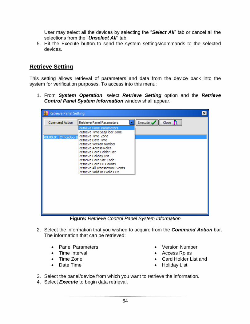
Retrieve Setting This setting allows retrieval of parameters and data from the device back into the system for verification purposes. To access into this menu:
1. From System Operation, select Retrieve Setting option and the Retrieve Control Panel System Information window shall appear.
Figure: Retrieve Control Panel System Information
2. Select the information that you wished to acquire from the Command Action bar.
The information that can be retrieved:
Panel Parameters
Time Interval
Time Zone
Date Time
Version Number
Access Roles
Card Holder List and
Holiday List
3. Select the panel/device from which you want to retrieve the information. 4. Select Execute to begin data retrieval.
65
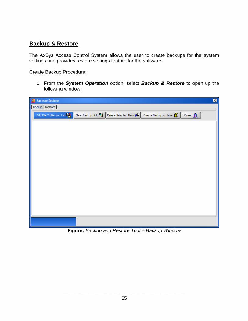
Backup & Restore The AxSys Access Control System allows the user to create backups for the system settings and provides restore settings feature for the software. Create Backup Procedure:
1. From the System Operation option, select Backup & Restore to open up the following window.
Figure: Backup and Restore Tool – Backup Window

66
2. Click on the “Add File to Backup List” tab, the software will prompt user to
select the file type that wished to be saved as backup. There’re two types of file that can be saved as backup: System Data File and the Transaction Log File.
Figure: File Selection Window
3. After selecting the file type, the user may now select the file that wished to be
saved as backup. You may select files from different folder by toggling the Look In field from the selection window (or the Open window).
4. From the selection window, click on the Open tab to open up the file that wished to be saved as backup.
5. Select the “Create Backup Archive” tab to compile and save the backup files. Assert the name for the backup files in the designated field, select “Save” to complete the procedure.
Selecting the Clear Backup List tab will delete all the backup items on the list.

67
System Restore Procedure:
1. From System Operation menu, select Backup & Restore option to open up the Backup and Restore Tool window. Select the “Restore” tab on the top left corner of the window to open up the Restore Window as shown below.
Figure: Backup and Restore Tool – Restore Window
2. Select the folder where you saved your backups, the list of backup items shall be
shown in the field under the folder column. 3. From that field, select the file that you wished to restore to the system. The
backup item’s information shall be displayed at the Archive Title field and the Content field.
4. Select the Restore Mode for the system restoration procedure. 5. Choose the Restore Path for the system. Original Path selection will overwrite
the existing files. Selecting Other Path option will provides restoration on different file path, in which the user is required to specify.
6. Select the Restore Backup File to complete the system restoration procedure.

68
Reindex Database The reindex feature allows the Access Control System to re-arrange the database management to allow better and faster processing for the system. To begin the reindex procedure, just select the System Operation menu from the tool bar or from the side panel to bring down the option list, select Reindex Database and the system shall perform the procedure automatically.
Figure: Reindex window
Load Report The Load Report option allows the user to load the saved reports for preview, print and backup purposes. To load a saved report, select System Operation menu from the tool bar or from the side panel, select Load Report (Load Saved Report) option to view the saved reports in the Print Preview window.
Click on the Load Report icon ( ) from the print preview window, then select the QRP report file for preview.
Figure: Load Report Print Preview Window

69
Lost & Replace This function used to delete the lost card record and generate a new card user record in the system database as well as control panel database.
Figure: Lost & Replace Window
To start perform card replace process, user is requires to click on “lost & Replace” button, system will launch the following window. Just specify the new card number in the new card number column. Press “OK” system will automatically terminate the previous card record with indication in the card record and added a new specified card number in the database.

70
Figure: Lost & Replace Record Entry Window
Figure: Lost & Replace: Card Terminated
In order to fully delete the terminate card record, system user requires to delete the card record at Card User Menu.

71
PART IV: DEVICE CONFIGURATION USING KEYPAD
Primary Settings and Defaults The Access Control System device offers special feature to work as a standalone device without the software/PC support. All it requires is to be connected to a 20×2 LCD Module with a 4×4 Keypad for system configuration. Be reminded to turn off the main power source before performing any Keypad and LCD Module installation. The configuration is explained in the following section. Steps to Perform “Cold Start”
1. Press and hold the Cold Start button for 6 second or until all relay triggered ON. 2. Release Cold Start button. 3. Wait until hearing a long beeping sound (and “Cold Start” message on the LCD). 4. Wait until all relay trigger OFF. 5. The device is now initialized to default setting.
Steps to Perform Quick Install
1. Press and hold the Mode button for 6 second until relay 1 trigger ON. 2. Flash access card at either IN reader or OUT reader to capture card. 3. Double beep sound as indicator when success install card. 4. Power reset controller to end the quick install menu. Note: When perform this steps, controller will automatically configure its operation mode as according to following setting.
DS1 and DS2 jump to GND : Configured as Dual Door Mode. DS1 shorted to GND and DS2 open : Configured as Single Door Mode. DS1 and DS2 open : Configured as Dual Door Mode.
Manufacturer’s Default Setting
System mode initialized to single door mode.
All transaction logs have been cleared.
All system databases have been cleared.
Master password pre-set to default [123456].

72
TAKE NOTE: The passwords for system configuration can be changed by users. Keypad’s Key Function
Key Function
0 1 2 3 4 5 6 7 8 9
Key 0 or letter [A,B,C] or Toggle key Key 1 or letter [D,E,F] Key 2 or letter [G,H,I] Key 3 or letter [J,K,L] Key 4 or letter [M,N,O] Key 5 or letter [P,Q,R] Key 6 or letter [S,T,U] Key 7 or letter [V,W,X] Key 8 or letter [Y,Z] Key 9 or Space
* Cancel or Back Space or Return to previous menu.
# Enter key or Accept key
A Main Menu Entry Key
D Exit Programming Menu
C Shift Menu Down
B Shift Menu UP
TAKE NOTE:
1. Press any key to activate the LCD and bring up the Password Menu, 2. Operation on Time Attendance Mode
[#] key is used as shift toggle key for OUT Shift selection [*] key is used as shift toggle key for IN Shift selection

73
Programming Steps
To Configure Controller RTC Clock. 1. Press [A] to trigger programming menu. 2. Key in 6 digit default password. 3. Press [#] to select [1.System Menu]. 4. Press [#] to select [1.System Param]. 5. Press [C] key to shift down to [1. Set RTC Clock], Press [#] to select. 6. Key in 10 digits Clock accordingly to YYMMDDhhmm format. 7. Keep pressing [C] key to shift menu down to [Quit] or
Press [D] key to quit programming menu.
To configure controller type 1. Press [A] to trigger programming menu. 2. Key in 6 digit default password. 3. Press [#] to select [1.System Menu]. 4. Press [#] to select [1.System Param]. 5. Press [#] to choose [2.Panel Type]. 6. Key in 2 digits panel mode as refer to following.
[00] : Single Door Mode. [01] : Two IN Door Mode. [02] : IN Barrier / OUT Barrier Mode [03] : Emergency Door Mode. (Not applicable) [04] : Time Attendance Mode. [05] : 2 IN Barrier Mode. [06] : 2 OUT Barrier Mode. [07] : Alarm Mode. (Not applicable)
6. Keep pressing [C] key to shift menu down to [Quit] or Press [D] key to quit programming menu.
To configure GP Output Time Zone 1. Press [A] to trigger programming menu. 2. Key in 6 digit default password. 3. Press [#] to select [1.System Menu]. 4. Press [#] to select [1.System Param]. 5. Press [#] to choose [3.GP Output Tz]. 6. Key in 3 digit time zone ranging 000 to 255. 7. Keep pressing [C] key to shift menu down to [Quit] or 8. Press [D] key to quit programming menu.
74
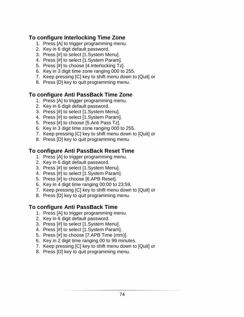
To configure Interlocking Time Zone 1. Press [A] to trigger programming menu. 2. Key in 6 digit default password. 3. Press [#] to select [1.System Menu]. 4. Press [#] to select [1.System Param]. 5. Press [#] to choose [4.Interlocking Tz]. 6. Key in 3 digit time zone ranging 000 to 255. 7. Keep pressing [C] key to shift menu down to [Quit] or 8. Press [D] key to quit programming menu.
To configure Anti PassBack Time Zone
1. Press [A] to trigger programming menu. 2. Key in 6 digit default password. 3. Press [#] to select [1.System Menu]. 4. Press [#] to select [1.System Param]. 5. Press [#] to choose [5.Anti Pass Tz]. 6. Key in 3 digit time zone ranging 000 to 255. 7. Keep pressing [C] key to shift menu down to [Quit] or 8. Press [D] key to quit programming menu.
To configure Anti PassBack Reset Time 1. Press [A] to trigger programming menu. 2. Key in 6 digit default password. 3. Press [#] to select [1.System Menu]. 4. Press [#] to select [1.System Param]. 5. Press [#] to choose [6.APB Reset]. 6. Key in 4 digit time ranging 00:00 to 23:59. 7. Keep pressing [C] key to shift menu down to [Quit] or 8. Press [D] key to quit programming menu.
To configure Anti PassBack Time 1. Press [A] to trigger programming menu. 2. Key in 6 digit default password. 3. Press [#] to select [1.System Menu]. 4. Press [#] to select [1.System Param]. 5. Press [#] to choose [7.APB Time (mm)]. 6. Key in 2 digit time ranging 00 to 99 minutes. 7. Keep pressing [C] key to shift menu down to [Quit] or 8. Press [D] key to quit programming menu.

75
To configure Visitor Duration
1. Press [A] to trigger programming menu. 2. Key in 6 digit default password. 3. Press [#] to select [1.System Menu]. 4. Press [#] to select [1.System Param]. 5. Press [#] to choose [8.Visitor Duration]. 6. Key in 3 digit ranging 000 to 255 minutes. 7. Keep pressing [C] key to shift menu down to [Quit] or 8. Press [D] key to quit programming menu.
To configure Scan Delay 1. Press [A] to trigger programming menu. 2. Key in 6 digit default password. 3. Press [#] to select [1.System Menu]. 4. Press [#] to select [1.System Param]. 5. Press [#] to choose [9. Scan Delay]. 6. Key in 3 digit ranging 000 to 199 minutes. 7. Keep pressing [C] key to shift menu down to [Quit] or 8. Press [D] key to quit programming menu.
To configure Access Limit 1. Press [A] to trigger programming menu. 2. Key in 6 digit default password. 3. Press [#] to select [1.System Menu]. 4. Press [#] to select [1.System Param]. 5. Press [#] to choose [10. Access Limit]. 6. Key in 4 digit time zone ranging 0000 to 9999 minutes. 7. Keep pressing [C] key to shift menu down to [Quit] or 8. Press [D] key to quit programming menu
To configure Security Mode High/Low 1. Press [A] to trigger programming menu. 2. Key in 6 digit default password. 3. Press [#] to select [1.System Menu]. 4. Press [#] to select [1.System Param]. 5. Press [#] to choose [11. Security Mode]. 6. Key in [1] to turn High, [0] to Low. 7. Keep pressing [C] key to shift menu down to [Quit] or 8. Press [D] key to quit programming menu

76
To Configure Menu Password
1. Press [A] to trigger programming menu. 2. Key in 6 digit default password. 3. Press [#] to select [1.System Menu]. 4. Press [#] to select [1.System Param]. 5. Press [C] key to shift down to [4. Program Password], Press [#] to select. 6. Key in 6 digits new password. 7. Keep pressing [C] key to shift menu down to [Quit] or
Press [D] key to quit programming menu.
To configure Lock Release Timer 1. Press [A] to trigger programming menu. 2. Key in 6 digit default password. 3. Press [#] to select [1.System Menu]. 4. Press [#] to select [2.Door 1 Menu] or [3.Door 2 Menu]. 5. Press [C] key to shift down to [1. Lock Release Timer ], Press [#] to select. 6. Key in 2 digits timer. Ranging from [00] to [90] second. 7. Keep pressing [C] key to shift menu down to [Quit] or
Press [D] key to quit programming menu.
To Configure Door Open Timer 1. Press [A] to trigger programming menu. 2. Key in 6 digit default password. 3. Press [#] to select [1.System Menu]. 4. Press [#] to select [2.Door 1 Menu] or [3.Door 2 Menu]. 5. Press [C] key to shift down to [2. Dr Open Timer ], Press [#] to select. 6. Key in 2 digits timer. Ranging from [00] to [90] second. 7. Keep pressing [C] key to shift menu down to [Quit] or 8. Press [D] key to quit programming menu

77
To Configure Reader Type 1. Press [A] to trigger programming menu. 2. Key in 6 digit default password. 3. Press [#] to select [1.System Menu]. 4. Press [#] to select [2.Door 1 Menu] or [3.Door 2 Menu]. 5. Press [C] key to shift down to [3. Reader Type], Press [#] to select. 6. Key in 2 digits reader type as accordingly to following code
[00] = ABA Reader [01] = Wiegand Reader [02] = HID Keypad Reader [03] = Rosslare Keypad Reader [04] = Indala Keypad Reader [05] = User Define Wiegand Format [06] = Card/Keypad Format [07] = LCD+Keypad Reader
7. Keep pressing [C] key to shift menu down to [Quit] or 8. Press [D] key to quit programming menu
To Configure Anti PassBack IN Location Code 9. Press [A] to trigger programming menu. 10. Key in 6 digit default password. 11. Press [#] to select [1.System Menu]. 12. Press [#] to select [2.Door 1 Menu] or [3.Door 2 Menu]. 13. Press [C] key to shift down to [4. AP IN Loc Code], Press [#] to select. 14. Key in 2 digits code. Ranging from [00] to [90]. 15. Keep pressing [C] key to shift menu down to [Quit] or 16. Press [D] key to quit programming menu
To Configure Anti PassBack OUT Location Code 1. Press [A] to trigger programming menu. 2. Key in 6 digit default password. 3. Press [#] to select [1.System Menu]. 4. Press [#] to select [2.Door 1 Menu] or [3.Door 2 Menu]. 5. Press [C] key to shift down to [5. AP OUT Loc Code], Press [#] to select. 6. Key in 2 digits code. Ranging from [00] to [90]. 7. Keep pressing [C] key to shift menu down to [Quit] or 8. Press [D] key to quit programming menu

78
To Configure Card Expiry Mode 1. Press [A] to trigger programming menu. 2. Key in 6 digit default password. 3. Press [#] to select [1.System Menu]. 4. Press [#] to select [2.Door 1 Menu] or [3.Door 2 Menu]. 5. Press [C] key to shift down to [6. Check Expiry], Press [#] to select. 6. Key in [1] to turn ON, [0] to turn OFF. 7. Keep pressing [C] key to shift menu down to [Quit] or 8. Press [D] key to quit programming menu
To Configure Push Button Time Zone 1. Press [A] to trigger programming menu. 2. Key in 6 digit default password. 3. Press [#] to select [1.System Menu]. 4. Press [#] to select [2.Door 1 Menu] or [3.Door 2 Menu]. 5. Press [C] key to shift down to [7.Push Button Tz], Press [#] to select. 6. Key in 3 digits time zone. Ranging from [000] to [255] 7. Keep pressing [C] key to shift menu down to [Quit] or 8. Press [D] key to quit programming menu
To Configure Card + PIN Time Zone 1. Press [A] to trigger programming menu. 2. Key in 6 digit default password. 3. Press [#] to select [1.System Menu]. 4. Press [#] to select [2.Door 1 Menu] or [3.Door 2 Menu]. 5. Press [C] key to shift down to [8.Card+Pin Tz], Press [#] to select. 6. Key in 3 digits time zone. Ranging from [000] to [255] 7. Keep pressing [C] key to shift menu down to [Quit] or 8. Press [D] key to quit programming menu
To Configure Buddy Mode Time Zone 1. Press [A] to trigger programming menu. 2. Key in 6 digit default password. 3. Press [#] to select [1.System Menu]. 4. Press [#] to select [2.Door 1 Menu] or [3.Door 2 Menu]. 5. Press [C] key to shift down to [9.Buddy Mode Tz], Press [#] to select. 6. Key in 3 digits time zone. Ranging from [000] to [255] 7. Keep pressing [C] key to shift menu down to [Quit] or 8. Press [D] key to quit programming menu

79
To Configure Auto Lock Release Time Zone 1. Press [A] to trigger programming menu. 2. Key in 6 digit default password. 3. Press [#] to select [1.System Menu]. 4. Press [#] to select [2.Door 1 Menu] or [3.Door 2 Menu]. 5. Press [C] key to shift down to [10.Auto Lock Rel Tz], Press [#] to select. 6. Key in 3 digits time zone. Ranging from [000] to [255] 7. Keep pressing [C] key to shift menu down to [Quit] or 8. Press [D] key to quit programming menu
To Configure Security ON/OFF 1. Press [A] to trigger programming menu. 2. Key in 6 digit default password. 3. Press [#] to select [1.System Menu]. 4. Press [#] to select [2.Door 1 Menu] or [3.Door 2 Menu]. 5. Press [C] key to shift down to [11. Security ON/OFF], Press [#] to select. 6. Key in [1] to turn ON, [0] to turn OFF. 7. Keep pressing [C] key to shift menu down to [Quit] or 8. Press [D] key to quit programming menu
To Configure User Define Wiegand code. 1. Press [A] to trigger programming menu. 2. Key in 6 digit default password. 3. Press [#] to select [1.System Menu]. 4. Press [#] to select [2.Door 1 Menu] or [3.Door 2 Menu]. 5. Press [C] key to shift down to [3. Reader Type], Press [#] to select. 6. Key in [05], 7. Press [C] key to shift down to [1.Fac Code Start],Press[#] to select 8. Key in 2 digit code, ranging [00] to [99]. 9. Repeat step 7 to select others parameter. 10. Keep pressing [C] key to shift menu down to [Quit] or 11. Press [D] key to quit programming menu
To Configure Auto PIN No and Pin Time Zone 1. Press [A] to trigger programming menu. 2. Key in 6 digit default password. 3. Press [#] to select [1.System Menu]. 4. Press [#] to select [4.Auto Pin Menu]. 5. Press [C] key to shift down to [01.Auto Pin No], Press [#] to select. 6. Key in 6 digits PIN. Ranging from [000000] to [999999] 7. Repeat step 5 for others PIN entry. 8. Keep pressing [C] key to shift menu down to [Quit] or 9. Press [D] key to quit programming menu

80
To batch install card database 1. Press [A] to trigger programming menu. 2. Key in 6 digit default password. 3. Press [C] to shift down menu to [2. Card Dbase Menu]. Press [#] to select. 4. Press [#] key to select [2. Batch Install]. 5. Key in 10 digits card numbers. 6. Key in 4 digits numbers of card to install. Ranging [0001] to [9999]. System will
install the card number start from user defined at step 5 to numbers of card defined in sequence.
7. Keep pressing [C] key to shift menu down to [6.Quit] or Press [D] key to quit programming menu.
To delete individual card 1. Press [A] to trigger programming menu. 2. Key in 6 digit default password. 3. Press [C] to shift down menu to [2. Card Dbase Menu]. Press [#] to select. 4. Press [#] key to select [3. Delete Card]. 5. Key in 10 digits card numbers or user flash card at reader. 6. Keep pressing [C] key to shift menu down to [6.Quit] or
Press [D] key to quit programming menu.
To clear card database 1. Press [A] to trigger programming menu. 2. Key in 6 digit default password. 3. Press [C] to shift down menu to [2. Card Dbase Menu]. Press [#] to select. 4. Press [#] key to select [4. Clear Card DB]. 5. Wait system to erase all card database in the memory. 6. Keep pressing [C] key to shift menu down to [6.Quit] or
Press [D] key to quit programming menu.
To Clear Anti Passback Flag for all card holder
1. Press [A] to trigger programming menu. 2. Key in 6 digit default password. 3. Press [#] to select [1.System Param Menu]. 4. Press [C] key to shift down to [8. Clear Card AP], Press [#] to select. 5. Wait controller to perform clearing. System will show complete once finished. 6. Keep pressing [C] key to shift menu down to [9.Quit] or
Press [D] key to quit programming menu.

81
To install card database 1. Press [A] to trigger programming menu. 2. Key in 6 digit default password. 3. Press [C] to shift down menu to [2. Card Dbase Menu]. Press [#] to select. 4. Press [#] key to select [1. Install Card]. 5. Key in 10 digits card numbers or user flash card at reader. 6. System will shift to [2. Card Expiry]. Press [C] to shift menu to [6.Quit]. or
Press [D] key to quit programming menu. Info: If user required to edit Card Expiry, at [2. Card Expiry]. Press [#] to select. Please key in 6 digits key formatted as YYMMDD. If user required to edit card access level, at [3. Access Level]. Press [#] to select. Please key in 3 digits key ranging [000] to [255]. If user required to edit card PIN, at [4. Card Pin]. Press [#] to select. Please key in 6 digits card PIN.
To Configure Facility Code (Site Code) 1. Press [A] to trigger programming menu. 2. Key in 6 digit default password. 3. Press [C] to shift down menu to [2. Card Dbase Menu]. Press [#] to select. 4. Press [#] key to select [5. Facility Code]. 5. Keep pressing[C] key to select facility code entry menu. 6. Press [#] to select and key in 4 digits Facility Code. 7. Keep pressing [C] key to shift menu down to [6.Quit] or 8. Press [D] key to quit programming menu.
To Configure Time Set 1. Press [A] to trigger programming menu. 2. Key in 6 digit default password. 3. Press [C] to shift down menu to [3.Time Setting Menu]. Press [#] to select. 4. Press [C] to shift down menu to [1.TimeSet Menu].Press [#] to select. 5. Press [#] to key in 3 digits time set no. 6. Press [#] to select interval and Key in 8 digit time interval ranging [0000] : [2359]. 7. Press [C] to shift to interval 2 and 3. 8. Repeat step 6. 9. Keep pressing [C] key to shift menu down to [Quit] or 10. Press [D] key to quit programming menu.

82
To Configure Time Zone 1. Press [A] to trigger programming menu. 2. Key in 6 digit default password. 3. Press [C] to shift down menu to [3.Time Setting Menu]. Press [#] to select. 4. Press [C] to shift down menu to [2.Time ZoneMenu].Press [#] to select. 5. Press [#] to key in 3 digits time zone no. 6. Press [#] to select day and Key in 3 digits time set ranging [000] to [255]. 7. Press [C] to select others day. 8. Repeat step 6. 9. Keep pressing [C] key to shift menu down to [Quit] or 10. Press [D] key to quit programming menu..
To Configure Holiday Date 1. Press [A] to trigger programming menu. 2. Key in 6 digit default password. 3. Press [C] to shift down menu to [3.Time Setting Menu]. Press [#] to select. 4. Press [C] to shift down menu to [4.Holiday Menu]. Press [#] to select. 5. Press [#] to key in 2 digits holiday no. 6. Press [#] to select day and Key in 4 digits date DDMM. 7. Repeat step 4 for others holiday Max.60. 8. Keep pressing [C] key to shift menu down to [Quit] or 9. Press [D] key to quit programming menu.
To Configure Door Access Level 1. Press [A] to trigger programming menu. 2. Key in 6 digit default password. 3. Press [C] to shift down menu to [4.Access Level Menu]. Press [#] to select. 4. Press [#] to key in 3 digits access level ranging 000 to 255. 5. Press [C] to select [1.Door 1 Time Zone]. 6. Press [#] to key in 3 digits time zone ranging 000 to 255. 7. Press [C] to shift [2.Door 2 Time Zone]. Repeat step 6. 8. Keep pressing [C] key to shift menu down to [Quit] or 9. Press [D] key to quit programming menu.

83
Controller onboard Speed Key function
1. Press [SEL] button on controller PCB for 6 second, will activate speed mode programming. ( After 6 beep sound, release button )
2. System will base on the controller DS1 input or DS2 input status to determine controller type that going to configure. DS1 open & DS2 Open : IN Barrier & OUT Barrier Mode. DS1 Close & DS2 Open : Single Door Mode. DS1 Close & DS2 Close : Two IN Door Mode.
3. Press [SEL] once to toggle RELAY1 ON to indicate system now is in CARD INSTALL MODE. Please flash card to install.
4. Press [SEL] once to toggle RELAY2 ON to indicate system now is in DELETE CARD MODE. Please flash card to delete.
5. Press [SEL] once to toggle RELAY3 ON to indicate system now is in ANTI PASSBACK MODE. Please toggle PB1 to GND to ON or OFF anti passback mode.
6. Please reset controller power to END operation. 7. User may directly reset controller power to end the operation after perform step
3,4or 5.

84
PART V: INDEX System Connection Diagram

85
Device Installation – Dual Door Mode

86
Device Installation – Car Parking Mode

87
Device Installation – Lift Access Control System

88
System Datasheet
Overall Features:
1. Multiple operating modes 2. Full external proximity connection 3. Supporting up to maximum of 5000 card users and 10000 log transactions
storages 4. Supports multiples proximity reading formation 5. Supports Alarm and General Purpose relay output 6. PC software connection for back end reporting and monitoring
System Features in Detail:
1. 5000 cars and 10000 log transaction storage 2. 255 sets of time interval sets 3. 255 sets of time zone settings 4. 255 sets of door access level 5. 60 sets of holidays setting 6. Door’s lock release time ranging from 0 to 99 seconds 7. Door’s open time ranging from 0 to 99 seconds 8. Support door lock auto release by time zone control 9. Support 2 doors access mode or 2 car park access mode 10. Support antipassback auto reset 11. Support 10 digits card number reading 12. Three operation modes are available
Card Only mode
Card & PIN mode
PIN only mode 13. Exit push button with time zone control 14. 10 facility code settings (Site Code) 15. 10 sets of local common PIN setting 16. Dual Card mode by time zone control (Buddy Mode) 17. Support integrated keypad reader via Wiegand connection 18. General purposes relay output by time zone control 19. Support PC downloading/uploading on system data 20. Support master card and alarm card mode 21. Duress alarm detection 22. Support Pulse door open, Security On/Off, Inhibit On/Off operations 23. Support Wiegand reader, ABA track 2 readers, HID keypad, Rosslare
keypad, ,Adalo Prox Reader and Indala keypad 24. Support 2 external buzzer and LED connection 25. Onboard LED and LCD for status display 26. 16 keypad connection onboard 27. Equipped with RT clock system with backup battery 28. Equipped with RS485 and RS232 connection on board

89
DC Electrical Specification
No Parameter Max.Limit
1 Operating Voltage 9VDC - 14VDC
2 Operating Current 500mA
3 Operating Frequency 20MHz
4 Operating Temperature
60 Celcuis
5 Operating Environment
0% to 95% non condensing
6 Processor 16bits MCU design
7 Non - volatile memory Flash Memory 128KBytes SRAM 1MBytes
8 Time & Clock Real Time Clock with supercap backup
9 Communication RS232 communication RS485 communication
10 Display 2x20 Characters LCD display module
11 Audible Alert Onboard 12VDC buzzer Each reader having own buzzer output
12 Output Point 1A Relay for door 1 lock system 1A Relay for second door lock system 1A Relay for General Purpose Output OR event output.
13 Input Point 4 TTL inputs for door sensor and push button. 2 TTL input for car parking sensor loop
14 Watchdog reset Built-in onboard external watchdog Built-in MCU internal watchdog
15 Power On Reset Equipped with 4.7Vdc triggering threshold voltage level.
16 Protection Built in TVS protection for every input point and communication cable