ek exit device retrofit kit - the global leader in door...
TRANSCRIPT
A8112C04/16
Copyright © 2016, Sargent Manufacturing Company, an ASSA ABLOY Group company. All rights reserved. Reproduction in whole or in part without the express written permission of Sargent Manufacturing Company is prohibited.
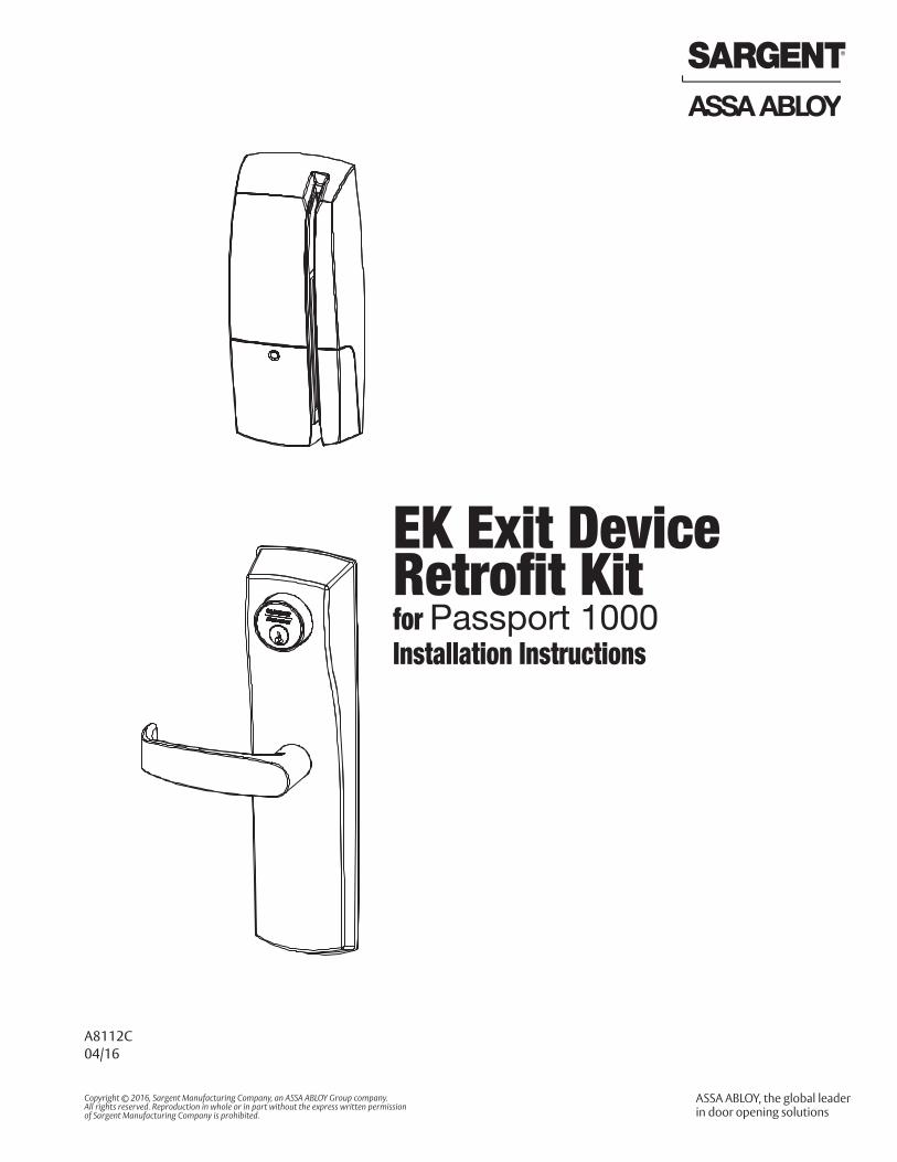
EK Exit Device Retrofit Kit for Passport 1000 Installation Instructions


3
Cop
yrig
ht ©
201
6, S
arge
nt M
anuf
actu
ring
Com
pany
, an
AS
SA
AB
LOY
Gro
up c
ompa
ny. A
ll rig
hts
rese
rved
. R
epro
duct
ions
in w
hole
or
in p
art w
ithou
t exp
ress
writ
ten
perm
issi
on o
f Sar
gent
Man
ufac
turin
g C
ompa
ny is
pro
hibi
ted.
04/3
0/16
1-800-810-WIRE • www.sargentlock.com • A8112C
To comply with “Fire Listed” doors, the batteries must be replaced with alkaline batteries only.
Any retrofit or other field modification to a fire rated opening can potentially impact the fire rating of the opening, and SARGENT® makes no representations or warranties concerning what such impact may be in any specific situation. When retrofitting any portion of an existing fire rated opening, or specifying and installing a new fire-rated opening, please consult with a code specialist or local code official (Authority Having Jurisdiction) to ensure compliance with all applicable codes and ratings.
Observe precautions for handling electrostatic sensitive devices.
!
1
2
3
4
5
6
Table of Contents
Warning ...................................................................................3
General Description .................................................................4
Hardware Specifications .........................................................4
Electronic Specifications .........................................................4
Installation Instructions ..........................................................5
Operational Check .................................................................23
Warning 1
FCCNOTE: This equipment has been tested and found to comply with the limits for a Class B digital device, pursuant to Part 15 of the FCC Rules. These limits are designed to provide reasonable protection against harmful interfer-ence in a residential installation.
This equipment generates, uses, and can radiate radio frequency energy and, if not installed and used in ac-cordance with the instructions, may cause harmful interference to radio communications. However, there is no guarantee that interference will not occur in a particular installation. If this equipment does cause harmful interfer-ence to radio or television reception, which can be determined by turning the equipment off and on, the user is encouraged to try to correct the interference by one or more of the following measures:
• Reorient or relocate the receiving antenna.
• Increase the separation between the equipment and receiver.
• Connect the equipment into an outlet on a circuit different from that to which the receiver is connected.
• Consult the dealer or an experienced radio/TV technician for help.
Industry Canada: Statement: The term “IC:” before the radio certification number only signifies that Industry Canada technical specifications were met.
This Class B digital apparatus meets all requirements of the Canadian Interference Causing Equipment Regula-tions. Operation is subject to the following two conditions: (1) this device may not cause harmful interference, and (2) this device must accept any interference received, including interference that may cause undesired operation.
Cet appareillage numérique de la classe B répond à toutes les exigences de l’interférence canadienne causant des règlements d’équipement. L’opération est sujette aux deux conditions suivantes: (1) ce dispositif peut ne pas causer l’interférence nocive, et (2) ce dispositif doit accepter n’importe quelle interférence reçue, y compris l’interférence qui peut causer l’opération peu désirée.
Changes or modifications to this unit not expressly approved by the party responsible for compliance could void the user’s authority to operate the equipment.

Cop
yrig
ht ©
201
6, S
arge
nt M
anuf
actu
ring
Com
pany
, an
AS
SA
AB
LOY
Gro
up c
ompa
ny. A
ll rig
hts
rese
rved
. R
epro
duct
ions
in w
hole
or
in p
art w
ithou
t exp
ress
writ
ten
perm
issi
on o
f Sar
gent
Man
ufac
turin
g C
ompa
ny is
pro
hibi
ted.
04/3
0/16
EK Exit Device Retrofit Kit for Passport 1000
1-800-810-WIRE • www.sargentlock.com • A8112C 4
The EK Exit Device Retrofit Kit is designed to link the SARGENT Passport 1000 Series P1/P2 product line with non-SARGENT rim exit devices. The EK Retrofit Kit is designed specifically to link to the Von Duprin® 98/99 Series rim exit device. Refer to Von Duprin Retrofit Chart (page 9) for replaceable Von Duprin exit trim. The P1/P2 Passport locks provide access control with magnetic swipe and optional contactless reader and/or keypad, as well as detailed audit capabilities.
For double door openings that require only a mechanical outside exit trim on one side of the opening, a dummy trim (706-5-EK1) is available. This option ensures a consistent aesthetic across both doors.
EK Exit Device Retrofit Kit for Passport 1000
• Retrofits existing Von Duprin 98/99 rim exit device. Consult the Von Duprin Retrofit Chart (page 9) for more specific information regarding the various trims that can be replaced.
• Outside lever is unlocked through access control credentials or mechanical key override • Accepts various rim cylinders (cylinder not included). For a partial list of cylinders by others, see table on
page 9.• Can be used with all P1 & P2 features• On-board memory• RX switch required (not included)*
• 2,400 users per lock; 10,000 event audit trail• Multiple time zone and holiday access scheduling• First-in unlock configuration, either by time or by
user (selectable)• Wireless (WiFi 802.11 b/g), battery-operated• Input Power: DC 9V, 1.5A (6 AA alkaline batteries
or optional hard-powered)• Uses existing Magstripe keycards (track 2)
Electronic Specifications4
Hardware Specifications3
General Description2
*Von Duprin® RX Switch Retrofit Kit (part number 050251-00) available through an authorized Von Duprin distributor.
P2
P1
• 2,400 users per lock; 10,000 event audit trail• Multiple time zone and holiday access scheduling• First-In unlock configuration, either by time or by
user (selectable)• Centralized lock management• Real time door status monitoring• Lockdown capable
• HID® multiCLASS SE® technology offers support for the following credentials:
• 2.4 GHz credential compatibility:• Secure Identity Object™ (SIO) on
Mobile IDs (Bluetooth Smart)
• 125 kHz credential compatibilty:
• HID Prox®
• 13.56 MHz credential compatibility:
• iCLASS®
• iCLASS SE® (SIO-enabled)
• iCLASS Seos®
• SIO on MIFARE® Classic
• SIO on MIFARE® DESfire® EV1
• MIFARE® Classic
• DESfire® EV1• NFC-enabled mobile phones
• Magnetic Stripe
04/3
0/16
Copy
right
© 2
016,
Sar
gent
Man
ufac
turin
g Co
mpa
ny, a
n AS
SA A
BLOY
Gro
up co
mpa
ny. A
ll rig
hts r
eser
ved.
Re
prod
uctio
ns in
who
le o
r in
part
with
out e
xpre
ss w
ritte
n pe
rmiss
ion
of S
arge
nt M
anuf
actu
ring
Com
pany
is p
rohi
bite
d.
EK Exit Device Retrofit Kit for Passport 1000
1-800-810-WIRE • www.sargentlock.com • A8112C5
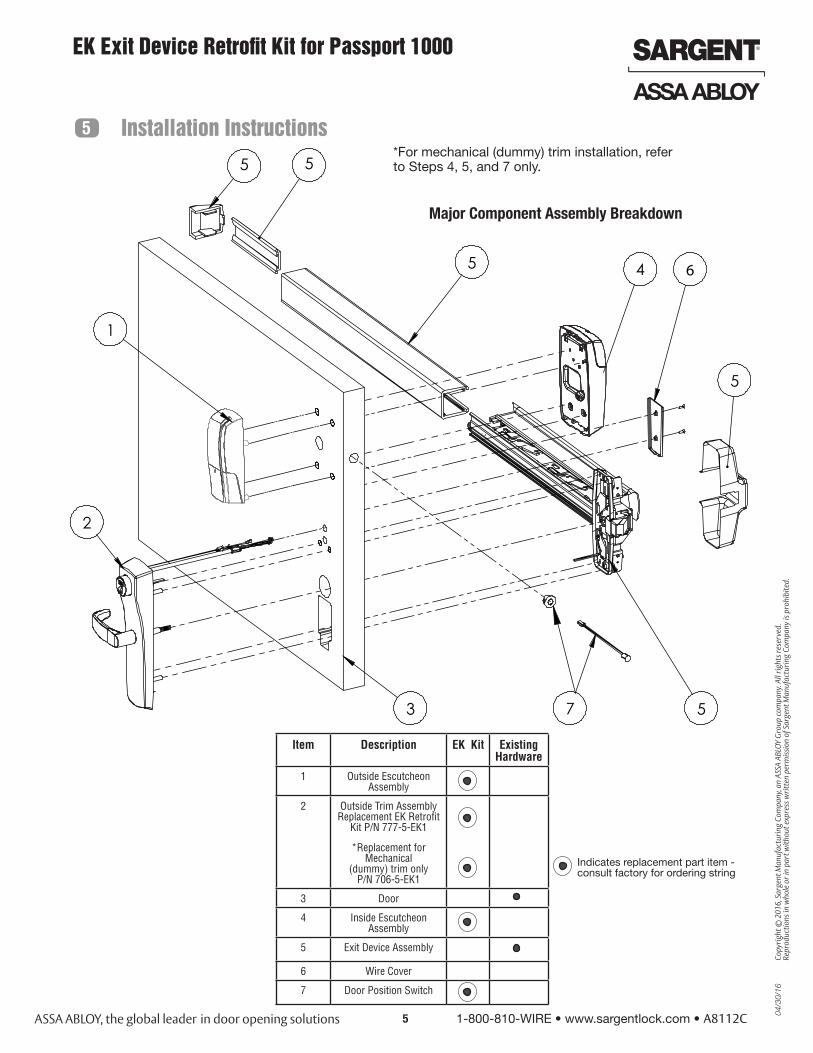
Item Description EK Kit Existing Hardware
1 Outside Escutcheon Assembly
2 Outside Trim Assembly Replacement EK Retrofit
Kit P/N 777-5-EK1
*Replacement for Mechanical
(dummy) trim only P/N 706-5-EK1
3 Door
4 Inside Escutcheon Assembly
5 Exit Device Assembly
6 Wire Cover
7 Door Position Switch
Installation Instructions5
1
3
4
5
5
2
5
55
6
Major Component Assembly Breakdown
Indicates replacement part item - consult factory for ordering string
7
*For mechanical (dummy) trim installation, refer to Steps 4, 5, and 7 only.

Cop
yrig
ht ©
201
6, S
arge
nt M
anuf
actu
ring
Com
pany
, an
AS
SA
AB
LOY
Gro
up c
ompa
ny. A
ll rig
hts
rese
rved
. R
epro
duct
ions
in w
hole
or
in p
art w
ithou
t exp
ress
writ
ten
perm
issi
on o
f Sar
gent
Man
ufac
turin
g C
ompa
ny is
pro
hibi
ted.
04/3
0/16
EK Exit Device Retrofit Kit for Passport 1000
1-800-810-WIRE • www.sargentlock.com • A8112C 6
1 Remove All Von Duprin® 98/99 Exit Hardware from Door
See diagram and part description on page 4 showing existing assemblies to be removed.
• Check hand of door.
The trim is field reversible.
Ensure exit trim is oriented to appropriate handing
• Door should be fitted and hung.
Left HandReverse
LHROutside
Inside
Right HandReverse
RHR
Fig. 2A
A. Verify Hand and Bevel of Door
B. Door Preparation
2 Door Preparation
• Based on 1-3/4” door thickness. Consult factory for other door thicknesses.• Use existing door prep (Fig. 2B) to locate templates.• Use A8104 (field prep template) or 4701 (door manufacturer template) for P1-prefix applications.• Use A8105 (field prep template) or 4700 (door manufacturer template) for P2-prefix applications.
Note: All instruction examples show wood door installation.• Refer to template for cutout requirements.
Outside of Door
Fig. 2B
Inside of Door
Note: highlighted sections indicate existing Von Duprin 996 trim cutouts.
Existing Von Duprin 996 trim
shown
04/3
0/16
Copy
right
© 2
016,
Sar
gent
Man
ufac
turin
g Co
mpa
ny, a
n AS
SA A
BLOY
Gro
up co
mpa
ny. A
ll rig
hts r
eser
ved.
Re
prod
uctio
ns in
who
le o
r in
part
with
out e
xpre
ss w
ritte
n pe
rmiss
ion
of S
arge
nt M
anuf
actu
ring
Com
pany
is p
rohi
bite
d.
EK Exit Device Retrofit Kit for Passport 1000
1-800-810-WIRE • www.sargentlock.com • A8112C7
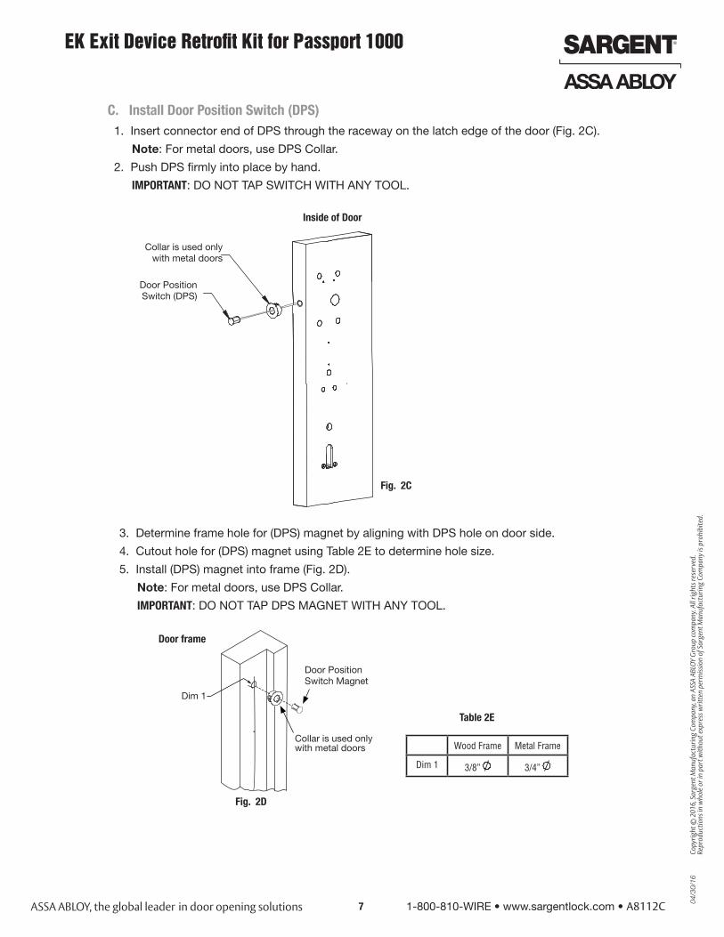
1. Insert connector end of DPS through the raceway on the latch edge of the door (Fig. 2C).
Note: For metal doors, use DPS Collar.
2. Push DPS firmly into place by hand.
IMPORTANT: DO NOT TAP SWITCH WITH ANY TOOL.
Fig. 2C
Collar is used onlywith metal doors
Door Position Switch (DPS)
Inside of Door
Wood Frame Metal Frame
Dim 1 3/8” 3/4”
C. Install Door Position Switch (DPS)
3. Determine frame hole for (DPS) magnet by aligning with DPS hole on door side.
4. Cutout hole for (DPS) magnet using Table 2E to determine hole size.
5. Install (DPS) magnet into frame (Fig. 2D).
Note: For metal doors, use DPS Collar.
IMPORTANT: DO NOT TAP DPS MAGNET WITH ANY TOOL.
Door frame
Door Position Switch Magnet
Dim 1
Fig. 2D
Table 2E
Collar is used only with metal doors
Cop
yrig
ht ©
201
6, S
arge
nt M
anuf
actu
ring
Com
pany
, an
AS
SA
AB
LOY
Gro
up c
ompa
ny. A
ll rig
hts
rese
rved
. R
epro
duct
ions
in w
hole
or
in p
art w
ithou
t exp
ress
writ
ten
perm
issi
on o
f Sar
gent
Man
ufac
turin
g C
ompa
ny is
pro
hibi
ted.
04/3
0/16
EK Exit Device Retrofit Kit for Passport 1000
1-800-810-WIRE • www.sargentlock.com • A8112C 8
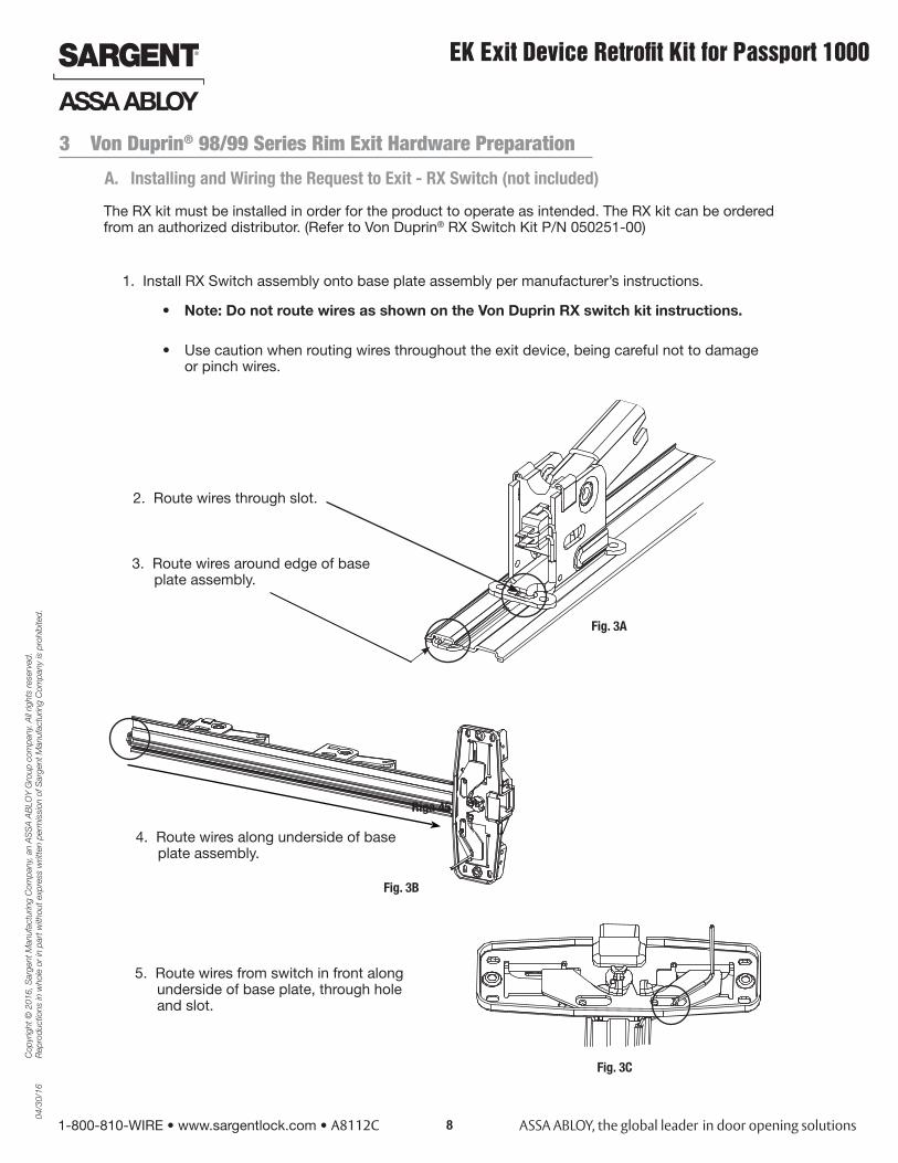
3 Von Duprin® 98/99 Series Rim Exit Hardware Preparation
The RX kit must be installed in order for the product to operate as intended. The RX kit can be ordered from an authorized distributor. (Refer to Von Duprin® RX Switch Kit P/N 050251-00)
1. Install RX Switch assembly onto base plate assembly per manufacturer’s instructions.
• Use caution when routing wires throughout the exit device, being careful not to damage or pinch wires.
• Note: Do not route wires as shown on the Von Duprin RX switch kit instructions.
2. Route wires through slot.
3. Route wires around edge of base plate assembly.
4. Route wires along underside of base plate assembly.
5. Route wires from switch in front along underside of base plate, through hole and slot.
A. Installing and Wiring the Request to Exit - RX Switch (not included)
Fig. 3A
Fig. 3B
Fig. 3C
Riga 45
04/3
0/16
Copy
right
© 2
016,
Sar
gent
Man
ufac
turin
g Co
mpa
ny, a
n AS
SA A
BLOY
Gro
up co
mpa
ny. A
ll rig
hts r
eser
ved.
Re
prod
uctio
ns in
who
le o
r in
part
with
out e
xpre
ss w
ritte
n pe
rmiss
ion
of S
arge
nt M
anuf
actu
ring
Com
pany
is p
rohi
bite
d.
EK Exit Device Retrofit Kit for Passport 1000
1-800-810-WIRE • www.sargentlock.com • A8112C9
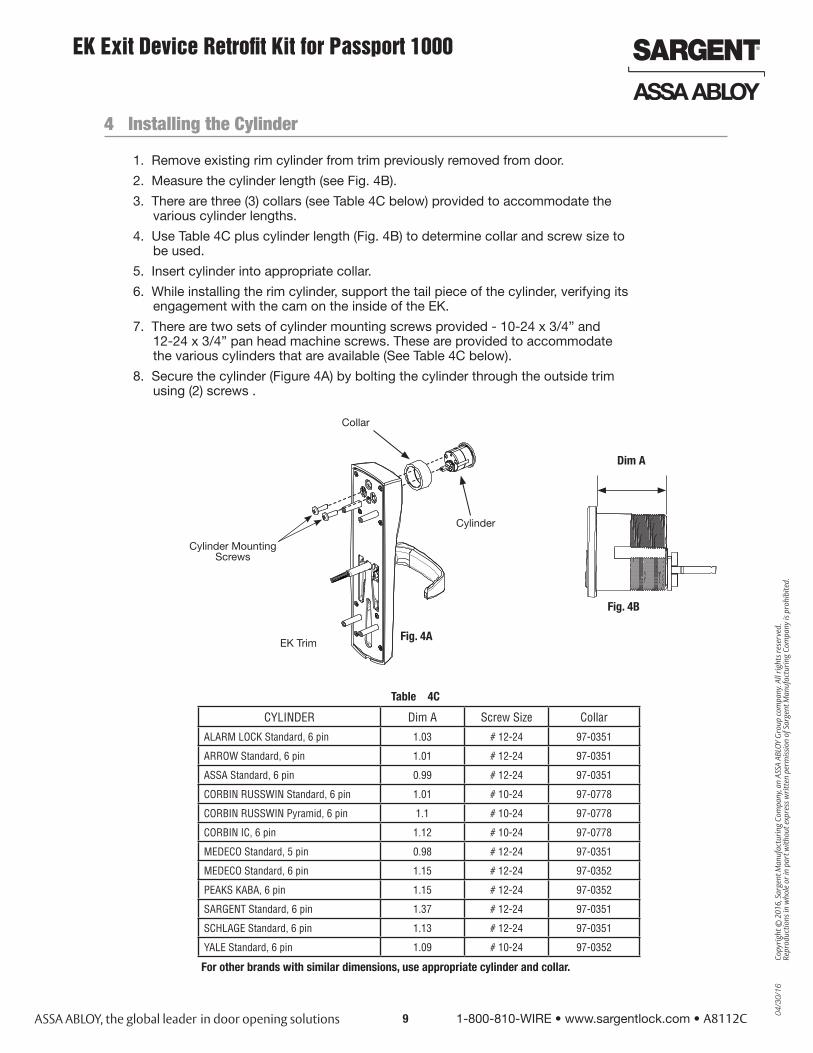
4 Installing the Cylinder
1. Remove existing rim cylinder from trim previously removed from door.
2. Measure the cylinder length (see Fig. 4B).
3. There are three (3) collars (see Table 4C below) provided to accommodate the various cylinder lengths.
4. Use Table 4C plus cylinder length (Fig. 4B) to determine collar and screw size to be used.
5. Insert cylinder into appropriate collar.
6. While installing the rim cylinder, support the tail piece of the cylinder, verifying its engagement with the cam on the inside of the EK.
7. There are two sets of cylinder mounting screws provided - 10-24 x 3/4” and 12-24 x 3/4” pan head machine screws. These are provided to accommodate the various cylinders that are available (See Table 4C below).
8. Secure the cylinder (Figure 4A) by bolting the cylinder through the outside trim using (2) screws .
CYLINDER Dim A Screw Size Collar
ALARM LOCK Standard, 6 pin 1.03 # 12-24 97-0351
ARROW Standard, 6 pin 1.01 # 12-24 97-0351
ASSA Standard, 6 pin 0.99 # 12-24 97-0351
CORBIN RUSSWIN Standard, 6 pin 1.01 # 10-24 97-0778
CORBIN RUSSWIN Pyramid, 6 pin 1.1 # 10-24 97-0778
CORBIN IC, 6 pin 1.12 # 10-24 97-0778
MEDECO Standard, 5 pin 0.98 # 12-24 97-0351
MEDECO Standard, 6 pin 1.15 # 12-24 97-0352
PEAKS KABA, 6 pin 1.15 # 12-24 97-0352
SARGENT Standard, 6 pin 1.37 # 12-24 97-0351
SCHLAGE Standard, 6 pin 1.13 # 12-24 97-0351
YALE Standard, 6 pin 1.09 # 10-24 97-0352
Table 4C
Fig. 4A
For other brands with similar dimensions, use appropriate cylinder and collar.
EK Trim
Cylinder
Collar
Fig. 4B
Cylinder Mounting Screws
Dim A

Cop
yrig
ht ©
201
6, S
arge
nt M
anuf
actu
ring
Com
pany
, an
AS
SA
AB
LOY
Gro
up c
ompa
ny. A
ll rig
hts
rese
rved
. R
epro
duct
ions
in w
hole
or
in p
art w
ithou
t exp
ress
writ
ten
perm
issi
on o
f Sar
gent
Man
ufac
turin
g C
ompa
ny is
pro
hibi
ted.
04/3
0/16
EK Exit Device Retrofit Kit for Passport 1000
1-800-810-WIRE • www.sargentlock.com • A8112C 10
5 Install Gasket - Required for Exterior Applications
Fig. 5A
6 Installing the EK
Item Exit Trim Exposed Hole(s) - see Note 2
1 992L No Exposed Holes
996L
992L-NL
996L-NL
2 992L-BE No Exposed Holes
996L-BE
992L-DT
996L-DT
3 992EO No Exposed Holes
996EO
4 994L No Exposed Holes
994L-NL
5 994L-BE No Exposed Holes
994L-DT
6 994EO No Exposed Holes
7 991K Exposed Hole(s)
991K-NL
8 991K-BE Exposed Hole(s)
991K-DT
9 990EO Exposed Hole(s)
10 990DT Exposed Hole(s)
11 990NL Exposed Hole(s)
12 990TP Exposed Hole(s)
13 990TP-BE Exposed Hole(s)
14 110NL No Exposed Holes
Note 1: The EK requires installiment of the NL drive screw.
Note 2: When the EK is retrofitted onto a 98/99 Rim Exit Device, depending on the Exit trim, there may be cutouts that are exposed. This column should be used as a reference to determine if there will be exposed holes (from existing Von Duprin prep).
Note 3: When the EK is retrofitted onto a 98/99 Exit Device, depending on the Exit trim, there may be paint shadows or door discoloration that is exposed from previously installed Von Duprin Rim Exit Trim hardware.
• The SARGENT EK Exit Device Retrofit Kit requires installation of the NL (Night Latch) Drive Screw (Fig. 6A) and is included with the EK Exit Device Retrofit Kit.
• The Von Duprin Retrofit Chart is a reference guide for determining if there will be any exposed cutouts when installing the SARGENT EK in place of the existing Von Duprin rim exit device.
NL Drive Screw (required)
Von Duprin Retrofit Chart
Fig. 6A
For exterior non-fire rated door applications, a gasket must be installed as a weatherseal between the escutcheon and the outside door surface.
Attach gasket to the outside escutcheon (Fig. 5A).

04/3
0/16
Copy
right
© 2
016,
Sar
gent
Man
ufac
turin
g Co
mpa
ny, a
n AS
SA A
BLOY
Gro
up co
mpa
ny. A
ll rig
hts r
eser
ved.
Re
prod
uctio
ns in
who
le o
r in
part
with
out e
xpre
ss w
ritte
n pe
rmiss
ion
of S
arge
nt M
anuf
actu
ring
Com
pany
is p
rohi
bite
d.
EK Exit Device Retrofit Kit for Passport 1000
1-800-810-WIRE • www.sargentlock.com • A8112C11
1. Connect Exit Device Retrofit Kit (EK) Orange wire to NC (normally closed) wire of RX chassis wire.
2. Connect EK Blue wire to COMMON wire of RX chassis wire.
It may be necessary to perform a continuity test on the rail wires to determine the NC and COM.
The wire that is determined to be NO (normally open) should be cut and insulated from contact.
3. Fasten each connection securely with wire nuts (supplied). Tuck connections and excess wire, being careful not to pinch or damage wires.
4. Position exit chassis carefully, verifying that the EK spindle engages the hub of the exit chassis.
5. Secure the exit chassis with through-bolts to the EK trim using (4) 10-32 x 1-1/2” pan head machine screws.
Orange
Blue
NC
COM
Door Position Switch (DPS)
Grounding Cable
Exit Trim Cable
DPS
Route wires and cables as shown in Fig. 7A.
Fig. 7A
Wire Nut
NC
COM
7 Mounting the EK
1. Position the wire cover plate above the chassis cover and covering the wires.
2. Use (2) 3/32” diameter by 1/2” deep holes (Fig. 8).
3. Cover wires with cover plate by securing plate to door directly above chassis (note orientation) using two (2) #6 x 1/2” flat head security torx wood screws (Fig. 8).
8 Install Wire Cover
Caution: Do not pinch wires when installing wire cover plate.
Inside of door
Fig. 8
Cover Plate
Cop
yrig
ht ©
201
6, S
arge
nt M
anuf
actu
ring
Com
pany
, an
AS
SA
AB
LOY
Gro
up c
ompa
ny. A
ll rig
hts
rese
rved
. R
epro
duct
ions
in w
hole
or
in p
art w
ithou
t exp
ress
writ
ten
perm
issi
on o
f Sar
gent
Man
ufac
turin
g C
ompa
ny is
pro
hibi
ted.
04/3
0/16
EK Exit Device Retrofit Kit for Passport 1000
1-800-810-WIRE • www.sargentlock.com • A8112C 12
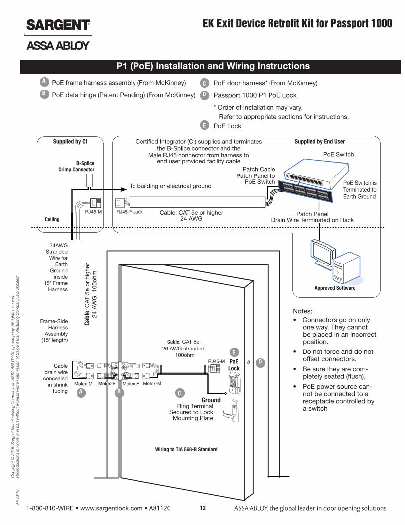
P1 (PoE) Installation and Wiring Instructions
PoE frame harness assembly (From McKinney)
PoE data hinge (Patent Pending) (From McKinney)
PoE door harness* (From McKinney)
Passport 1000 P1 PoE Lock
* Order of installation may vary. Refer to appropriate sections for instructions. PoE Lock
A
D
C
B
Patch PanelDrain Wire Terminated on Rack
Cable: CAT 5e or higher24 AWG
Molex-F Molex-F Molex-M
Cable: CAT 5e,26 AWG stranded,
100ohm
Wiring to TIA 568-B Standard
RJ45-M
Molex-M
RJ45-F Jack
Cabl
e: C
AT 5
e or
hig
her
24 A
WG
100
ohm
Approved Software
B-Splice Crimp Connector
Certified Integrator (CI) supplies and terminates the B-Splice connector and the
Male RJ45 connector from harness to end user provided facility cable
Supplied by End User
PoE Switch
PoE Lock
Ceiling
Supplied by CI
GroundRing Terminal
Secured to Lock Mounting Plate
PoE Switch isTerminated toEarth Ground
Patch Cable Patch Panel to
PoE Switch
Frame-SideHarness
Assembly(15' length)
24AWG Stranded
Wire for Earth
Ground inside
15' Frame Harness
Cable drain wire
concealed in shrink
tubing A B
E
D
C
Notes:• Connectors go on only
one way. They cannot be placed in an incorrect position.
• Do not force and do not offset connectors.
• Be sure they are com-pletely seated (flush).
• PoE power source can-not be connected to a receptacle controlled by a switch
E
To building or electrical ground
RJ45-M

04/3
0/16
Copy
right
© 2
016,
Sar
gent
Man
ufac
turin
g Co
mpa
ny, a
n AS
SA A
BLOY
Gro
up co
mpa
ny. A
ll rig
hts r
eser
ved.
Re
prod
uctio
ns in
who
le o
r in
part
with
out e
xpre
ss w
ritte
n pe
rmiss
ion
of S
arge
nt M
anuf
actu
ring
Com
pany
is p
rohi
bite
d.
EK Exit Device Retrofit Kit for Passport 1000
1-800-810-WIRE • www.sargentlock.com • A8112C13
Frame Harness Installation
Components and wire harness supplied by McKinney, Suggested installation:
RJ45-M
Molex-M
Cabl
e: C
AT 5
e or
hig
her
24 A
WG
100
ohm
B-Splice Crimp Connector
Ceiling
Supplied by CICut end / ceiling-side PoE harness:
Do not confuse pair numbers with pin numbers. A pair number is used for refer-ence only (eg: 10Base-T Ethernet uses pairs 2 & 3). The pin numbers indicate actual physical locations on the plug and jack.
1. Feed cut end of harness into hole on hinge-side through single access hole.
2. Push one connector back through the hole and feed into the other access hole.Each of the hinge-side harness connectors should end up threaded through a different access hole and matched to the same size pin connector from the door harness:
• 4-pin male molex connector.
• 6-pin male molex connector with ground wire.
Hinge side of PoE harness:Frame-Side
HarnessAssembly
(15' length)
24AWG Stranded
Wire for Earth
Ground inside
15' Frame Harness
Cable drain wire
concealed in shrink
tubing
A
Hinge-side harness connectors:
• 4-pin female molex connector
• 6-pin female molex connector with ground wire
Lock-side harness connectors:
• Ring terminal
• 4-pin female molex connector
• 6-pin female molex connector with ground wire
Installation Wiring (Continued)
TIA/EIA 568-B Standard Wiring
1 2 3 4 5 6 7 8 PIN Wire Pair
Number
1 White/Orange 2
2 Orange 2
3 White/Green 3
4 Blue 1
5 White/Blue 1
6 Green 3
7 White/Brown 4
8 Brown 4
1 8pin 8 1pin
4-pin M
6-pin M
FramePoE Hinge
PoE Data HingeB
4-pin F
6-pin F
4-pin F
6-pin F

Cop
yrig
ht ©
201
6, S
arge
nt M
anuf
actu
ring
Com
pany
, an
AS
SA
AB
LOY
Gro
up c
ompa
ny. A
ll rig
hts
rese
rved
. R
epro
duct
ions
in w
hole
or
in p
art w
ithou
t exp
ress
writ
ten
perm
issi
on o
f Sar
gent
Man
ufac
turin
g C
ompa
ny is
pro
hibi
ted.
04/3
0/16
EK Exit Device Retrofit Kit for Passport 1000
1-800-810-WIRE • www.sargentlock.com • A8112C 14
Installation Wiring (Continued)
Order of installation may vary. Refer to appropriate sections for instructions.
Hinge-side harness connectors:
• 4-pin male Molex connector
• 6-pin male Molex connector with ground wire
Lock-side harness connectors:
• Ring terminal
• male RJ45 connector (crimped after cable is fed through door)
Notes:
• Connectors go on only one way. They cannot be plugged to incorrect position.
• Do not force and do not offset connectors.
• Be sure they are completely seated (flush).
Order of installation may vary. Refer to appropriate sections for instructions.
1. Prop door open.
2. Using the ring terminal, carefully route the assembly through the door channel to the lock.
PoE Lock
4-pin F 4-pin M4-pin F
6-pin F 6-pin F 6-pin M
Cable: CAT 5e,26 AWG stranded,
100ohm
Drain Wire
D
C
RJ45-M
PoE Harness (cat5e)
PoE Door Harness
PoE Lock
04/3
0/16
Copy
right
© 2
016,
Sar
gent
Man
ufac
turin
g Co
mpa
ny, a
n AS
SA A
BLOY
Gro
up co
mpa
ny. A
ll rig
hts r
eser
ved.
Re
prod
uctio
ns in
who
le o
r in
part
with
out e
xpre
ss w
ritte
n pe
rmiss
ion
of S
arge
nt M
anuf
actu
ring
Com
pany
is p
rohi
bite
d.
EK Exit Device Retrofit Kit for Passport 1000
1-800-810-WIRE • www.sargentlock.com • A8112C15
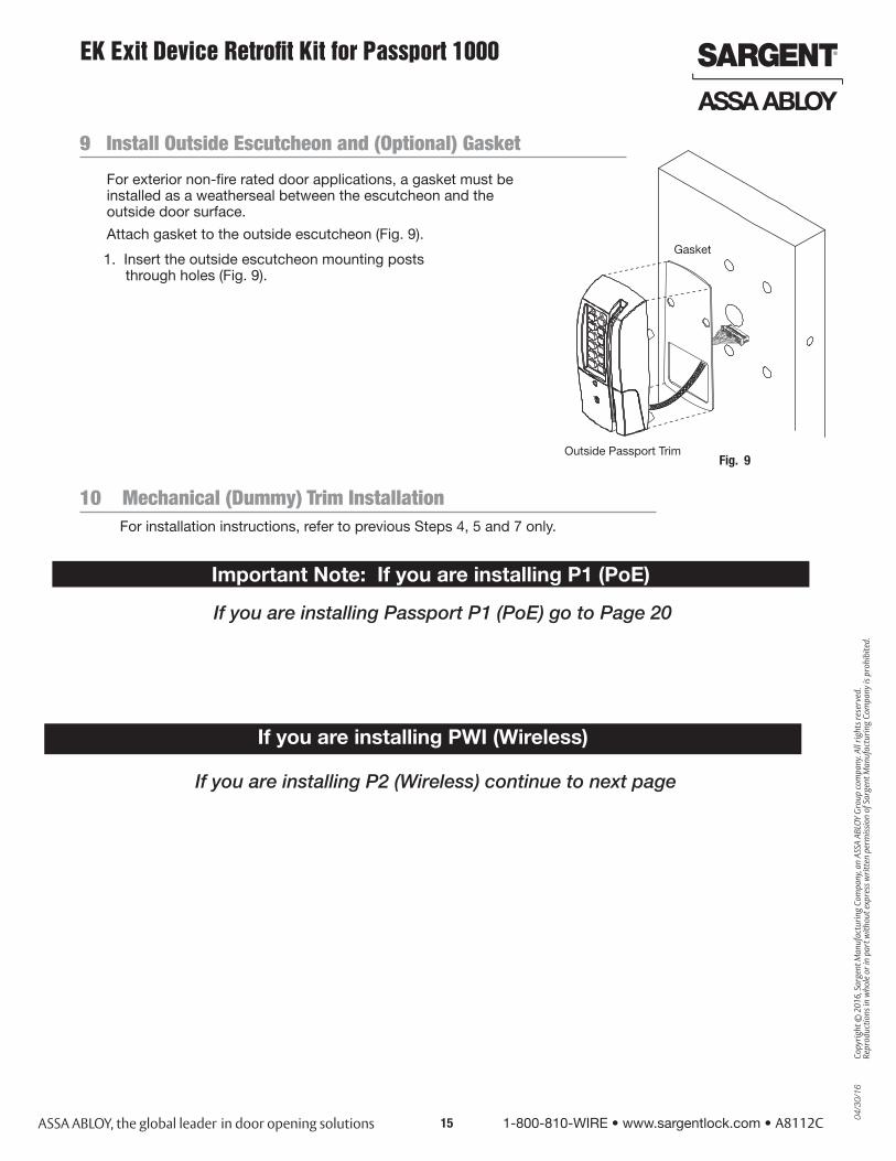
For exterior non-fire rated door applications, a gasket must be installed as a weatherseal between the escutcheon and the outside door surface.
Attach gasket to the outside escutcheon (Fig. 9).
Fig. 9Outside Passport Trim
Gasket
9 Install Outside Escutcheon and (Optional) Gasket
10 Mechanical (Dummy) Trim InstallationFor installation instructions, refer to previous Steps 4, 5 and 7 only.
1. Insert the outside escutcheon mounting posts through holes (Fig. 9).
If you are installing Passport P1 (PoE) go to Page 20
Important Note: If you are installing P1 (PoE)
If you are installing PWI (Wireless)
If you are installing P2 (Wireless) continue to next page

Cop
yrig
ht ©
201
6, S
arge
nt M
anuf
actu
ring
Com
pany
, an
AS
SA
AB
LOY
Gro
up c
ompa
ny. A
ll rig
hts
rese
rved
. R
epro
duct
ions
in w
hole
or
in p
art w
ithou
t exp
ress
writ
ten
perm
issi
on o
f Sar
gent
Man
ufac
turin
g C
ompa
ny is
pro
hibi
ted.
04/3
0/16
EK Exit Device Retrofit Kit for Passport 1000
1-800-810-WIRE • www.sargentlock.com • A8112C 16
(2) #8 - 3/8” Flat Head Wood Screws OR(2) #8 - 3/8” Flat Head Machine Screws
Fig. 10B
Outside Passport
Trim
Attach ground wire to lower left screw
Mounting Plate
Fig. 10A
1. On the inside of the door, position the mounting plate over the indicated holes (Fig. 10A).
2. Route DPS and reader wires/cables through side opening (Fig. 10A).
3. Route exit trim cable and ground wire through bottom of mounting plate.
4. Attach ground terminal to lower right corner using one #8-32 x 1-7/8” flat head machine screw.
Make sure plate is positioned upright (Fig. 10A).
5. Insert other three #8-32 x 1-7/8” flat head machine screws and tighten, fastening the outside escutcheon to the door (Fig. 10A).
IMPORTANT: If the following step is skipped, the product will not be UL-compliant:
6. Attach two (2) #8 x 3/8” flat head wood screws for wood doors or (2) #8-32 x 3/8” flat head machine screws for metal doors (Fig. 10B).
11 Install Outside Escutcheon and Mounting Plate Assembly
Exit TrimCable
Mounting Hole Posts
Note: Cable lengths exaggerated for illustrative purposes.
If you are installing P2 (Wireless) continue here

04/3
0/16
Copy
right
© 2
016,
Sar
gent
Man
ufac
turin
g Co
mpa
ny, a
n AS
SA A
BLOY
Gro
up co
mpa
ny. A
ll rig
hts r
eser
ved.
Re
prod
uctio
ns in
who
le o
r in
part
with
out e
xpre
ss w
ritte
n pe
rmiss
ion
of S
arge
nt M
anuf
actu
ring
Com
pany
is p
rohi
bite
d.
EK Exit Device Retrofit Kit for Passport 1000
1-800-810-WIRE • www.sargentlock.com • A8112C17
12 Installation of Connectors
CAUTION - Do not touch or allow debris to enter connector contacts.
Secure the following connectors to their respective terminals (Fig. 11A ):
A. Secure the 10-pin exit trim body assembly connector.
*NOTE: Optional 2-pin external 12-24VDC power connector (P2 wireless only) .
B. Tuck excess cable into wire hole on inside of door.
C. Finish securing mounting plate and reader to door by fully tightening through-bolts on inside of door.
Note: Ensure ground ring is positioned upright.
D. Secure the 24-pin card reader connector.
Wire Positioning:
Please follow these steps prior to installing inside escutcheon to prevent any damage caused by pinching wires:
Fig. 11B
DPS
Reader Cable
Mounting Plate
Position ground ring terminalupright, thentighten screw
Exit Trim Cable
Cop
yrig
ht ©
201
6, S
arge
nt M
anuf
actu
ring
Com
pany
, an
AS
SA
AB
LOY
Gro
up c
ompa
ny. A
ll rig
hts
rese
rved
. R
epro
duct
ions
in w
hole
or
in p
art w
ithou
t exp
ress
writ
ten
perm
issi
on o
f Sar
gent
Man
ufac
turin
g C
ompa
ny is
pro
hibi
ted.
04/3
0/16
EK Exit Device Retrofit Kit for Passport 1000
1-800-810-WIRE • www.sargentlock.com • A8112C 18
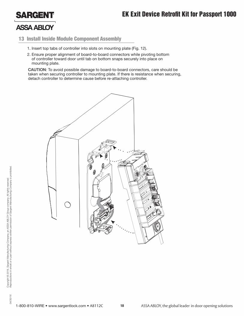
13 Install Inside Module Component Assembly
1. Insert top tabs of controller into slots on mounting plate (Fig. 12).
2. Ensure proper alignment of board-to-board connectors while pivoting bottom of controller toward door until tab on bottom snaps securely into place on mounting plate.
CAUTION: To avoid possible damage to board-to-board connectors, care should be taken when securing controller to mounting plate. If there is resistance when securing, detach controller to determine cause before re-attaching controller.
04/3
0/16
Copy
right
© 2
016,
Sar
gent
Man
ufac
turin
g Co
mpa
ny, a
n AS
SA A
BLOY
Gro
up co
mpa
ny. A
ll rig
hts r
eser
ved.
Re
prod
uctio
ns in
who
le o
r in
part
with
out e
xpre
ss w
ritte
n pe
rmiss
ion
of S
arge
nt M
anuf
actu
ring
Com
pany
is p
rohi
bite
d.
EK Exit Device Retrofit Kit for Passport 1000
1-800-810-WIRE • www.sargentlock.com • A8112C19
Fig. 14
15 Install Inside Escutcheon
1. Position inside escutcheon as shown (Fig. 14).
Verify that all wires are positioned within the escutcheon to avoid pinching.
2. Attach escutcheon with (2) #8-32 x 1/2” T-20 Torx pan head screws.
3. Straighten escutcheon and tighten securely.
DO NOT OVERTIGHTEN.
(2) #8-32 x 1/2” Torx Screws
Fig. 13
14 Install Battery Pack
For battery replacement:
When replacing the (6) “AA” alkaline batteries in the compartment, please note batteries must be replaced within five (5) minutes to prevent the internal clock from becoming inaccurate.
a. Place (6) “AA” alkaline batteries in the compartment, being careful to align polarity properly.
b. After batteries are installed, there is a slight delay; then LED will flash amber and the lock motor will cycle.
Before installing batteries for the first time:
Remove pull tab from its position beneath the coin cell by pulling on tab in direction of arrows printed on tab (Fig. 13).
Inside of Door
Coin Cell Pull Tab
P2 (Wireless) Installation Complete
Please proceed to Section 6 Operational Check (page 23)

Cop
yrig
ht ©
201
6, S
arge
nt M
anuf
actu
ring
Com
pany
, an
AS
SA
AB
LOY
Gro
up c
ompa
ny. A
ll rig
hts
rese
rved
. R
epro
duct
ions
in w
hole
or
in p
art w
ithou
t exp
ress
writ
ten
perm
issi
on o
f Sar
gent
Man
ufac
turin
g C
ompa
ny is
pro
hibi
ted.
04/3
0/16
EK Exit Device Retrofit Kit for Passport 1000
1-800-810-WIRE • www.sargentlock.com • A8112C 20
16 Installation of Connectors (PoE)
1. Tuck excess cable into wire hole on inside of door.
2. Secure the mounting assembly while ensuring proper alignment of outside reader and fully tighten the (2) through- bolts on the inside of the door to secure the reader and plate to the door.
Secure the following connectors to their respective terminals (Fig. 15A, B):
A. Secure the 4-pin DPS connector.
B. Secure the 10-pin lock body assembly connector.
CAUTION - Do not touch or allow debris to enter connector contacts.
Secure Mounting Plate
IMPORTANT: Do not run wires through bottom hole in plate (Fig. 15A, B) - it will damage wires and the controller connector. Route wires around flange, do not route wires through the flange hole (Fig. 15B).
C. Secure the 24-pin card reader connector (Fig. 15B).
D. Crimp* RJ45 to cat5e cable from hinge (Fig. 15C).
*For more detail, refer to section ‘Installation Wiring’, “A - Frame Harness Installation”.
Ground Lugs
DPS (4-pin)A
Lock Body (10-pin)
Fig. 15A
B
Reader (24-pin)
Board-to-Board Connector
Fig. 15B
TIA/EIA 568-B Standard Wiring
1 2 3 4 5 6 7 8
Do not confuse pair numbers with pin numbers. A pair number is used for reference only (eg: 10BaseT Ethernet uses pairs 2 & 3). The pin numbers indicate actual physical locations on the plug and jack.
PIN Wire Pair Number
1 White/Orange 2
2 Orange 2
3 White/Green 3
4 Blue 1
5 White/Blue 1
6 Green 3
7 White/Brown 4
8 Brown 4
Crimp* to RJ45-M Connector
Cat5e cable from hinge
RJ45-M
C
Fig. 15C
1 8pin 8 1pin
04/3
0/16
Copy
right
© 2
016,
Sar
gent
Man
ufac
turin
g Co
mpa
ny, a
n AS
SA A
BLOY
Gro
up co
mpa
ny. A
ll rig
hts r
eser
ved.
Re
prod
uctio
ns in
who
le o
r in
part
with
out e
xpre
ss w
ritte
n pe
rmiss
ion
of S
arge
nt M
anuf
actu
ring
Com
pany
is p
rohi
bite
d.
EK Exit Device Retrofit Kit for Passport 1000
1-800-810-WIRE • www.sargentlock.com • A8112C21
17 Installation of Inside Module Component Assembly (PoE)
1. Insert top tabs of controller into slots on mounting plate (Fig. 11A, B).
2. Ensure proper alignment of board-to-board connectors while pivoting bottom of controller toward door until tab on bottom snaps securely into place on mounting plate.
CAUTION: To avoid possible damage to board-to-board connectors, care should be taken when securing controller to mounting plate. If there is resistance when securing, detach controller to determine cause before re-attaching controller.
Fig. 11B
3. Connect RJ45 Male Connector to female RJ45 on controller board (Fig. 11B).
4. Remove pull tab from its position beneath the coin cell by pulling on tab in direction of arrows printed on tab (Fig. 12).
Fig. 11A

Cop
yrig
ht ©
201
6, S
arge
nt M
anuf
actu
ring
Com
pany
, an
AS
SA
AB
LOY
Gro
up c
ompa
ny. A
ll rig
hts
rese
rved
. R
epro
duct
ions
in w
hole
or
in p
art w
ithou
t exp
ress
writ
ten
perm
issi
on o
f Sar
gent
Man
ufac
turin
g C
ompa
ny is
pro
hibi
ted.
04/3
0/16
EK Exit Device Retrofit Kit for Passport 1000
1-800-810-WIRE • www.sargentlock.com • A8112C 22
Fig. 12
18 Install Inside Escutcheon
1. Position inside escutcheon as shown (Fig. 12).
Verify that all wires are positioned within the escutcheon to avoid pinching.
2. Attach escutcheon with (2) #8-32 x 1/2” T-20 Torx pan head screws.
3. Straighten escutcheon and tighten securely.
DO NOT OVERTIGHTEN.
(2) #8-32 x 1/2” Torx Screws

04/3
0/16
Copy
right
© 2
016,
Sar
gent
Man
ufac
turin
g Co
mpa
ny, a
n AS
SA A
BLOY
Gro
up co
mpa
ny. A
ll rig
hts r
eser
ved.
Re
prod
uctio
ns in
who
le o
r in
part
with
out e
xpre
ss w
ritte
n pe
rmiss
ion
of S
arge
nt M
anuf
actu
ring
Com
pany
is p
rohi
bite
d.
EK Exit Device Retrofit Kit for Passport 1000
1-800-810-WIRE • www.sargentlock.com • A8112C23
IMPORTANT: Be sure to test functions prior to closing door.
In all cases, perform the following checks:
1. Ensure that inside exit bar retracts latch.
• To test cylinder, the following checks apply:
Insert key into cylinder and rotate:
a. There should be no friction against lock case, wire harness, or any other obstructions. If friction or binding occurs, readjust cylinder and wiring harness to eliminate issues.
b. The key should unlock the outside lever and the lever should rotate freely.
• For units without a keypad, add card using LCT software* and then test.
• For units with a keypad, add pin and card using LCT software* and then test.
2. LED signaling:
• After using a valid credential, a green flash followed by three fast amber flashes indicates a low power condition.
Check the battery voltage.
If the voltage is low, replace the batteries.
• If the batteries die, the lock will flash rapid blue for approximately one minute.
The lock can be opened with valid cylinder key.
3. When you have completed the tests, close the door and press the rail ensuring door opens. Test with valid credential(s).
Operational Check6
*Refer to Network and Lock Configuration Tool user manual (WFMN1) for information on how to configure and program locks.

SARGENT Manufacturing100 Sargent DriveNew Haven, CT 06511 USA1-800-810-WIRE (9473) • www.sargentlock.com
Founded in the early 1800s, SARGENT® is a market leader in locksets, cylinders, door closers, exit devices,electro-mechanical products and access control systems for new construction, renovation, and replacement applications.The company’s customer base includes commercial construction, institutional, and industrial markets.
Copyright © 2016, Sargent Manufacturing Company, an ASSA ABLOY Group company. All rights reserved.Reproduction in whole or in part without the express written permission of Sargent Manufacturing Company is prohibited.HID and iCLASS are registered trademarks of HID Global Corporation. Von Duprin is a registered trademark of Von Duprin LLC.
ASSA ABLOY is the global leader in door opening solutions, dedicated tosatisfying end-user needs for security, safety and convenience.
A8112C 04/16