eis_fall_2015_de (1)
TRANSCRIPT


2 | Embedded Intel® Solutions — Fall 2015 | www.embeddedintel.com
FROM THE EDITOR
Embedded Intel ®Solutions is sent free to engineers and embedded developers in the U.S. and Canada who design with embedded Intel® processors.
Embedded Intel ®Solutions is published by Extension Media LLC, 1786 18th Street, San Francisco, CA 94107. Copyright © 2015 by Extension
Media LLC. All rights reserved. Printed in the U.S.
www.embeddedintel.com
Vice President & PublisherClair Bright
EditorialEditor-in-Chief
Chris [email protected]
Managing EditorAnne Fisher
Managing Editor - ChinaJane Lin-Li
Senior EditorsCaroline HayesDavid BurskyGabe Moretti
Creative/ProductionProduction ManagerStephanie BradburyGraphic Designers
Nicky JacobsonSimone Bradley
Media CoordinatorKyle Barreca
Senior Web DevelopersSlava Dotsenko
Mariam Moattari
Advertising / Reprint SalesVice President, Sales
Embedded Electronics Media GroupClair Bright
[email protected](415) 255-0390 ext. 15
Sales ManagerMichael Cloward
[email protected] (415) 255-0390 ext. 17
Marketing/CirculationJenna Johnson
To Subscribewww.embeddedintel.com
Extension Media, LLCCorporate Office
President and PublisherVince Ridley
[email protected](415) 255-0390 ext. 18
Vice President & PublisherClair Bright
Vice President, Business DevelopmentMelissa Sterling
Human Resources / AdministrationDarla Rovetti
Special Thanks to Our Sponsors
CES 2015 attendees spotted a connector that looks sort of like a micro USB,
but is way different. The USB 3.1 Type-C connector, according to the USB-IF
trade organization, has a 20-year life because it’s the do-everything connector.
Intel® notes, “Two dozen Intel engineers worked on the new connector.”
Look for the company to promote and support it in consumer PCs, laptops,
2:1’s and enterprise servers. And Intel’s Thunderbolt™ standard—used
almost exclusively on high-end Apple machines—will undergo a speed boost to 40 Gbps
and rely on the Type-C connector for Thunderbolt signals.
Here are four things you need to keep in mind for future embedded designs:
#1: It will run every serial protocol you’ve got.At 10 Gbps and a mere 12 wires, the connector, cable, and interface circuitry are designed
to not only run USB 3.1, but handle PCI Express, HDMI, DisplayPort, audio, power, and
so on. Provisions in the spec allow for many of these protocols to run simultaneously and
bi-directionally. For instance, USB 2.0 can run with 3.0 along with DisplayPort. This is
important because one connector/cable can really do it all. The capability to run protocols
simultaneously and bi-directionally simplifies the breakout connections on many
embedded PCBs, panels and cases. Interestingly, while the USB-IF specs out USB 3.1 over
Type-C at 10 Gbps, Intel’s Thunderbolt 3 will stream up to 40 Gbps. Clearly the design has
some headroom—giving credence to the “20-year life” assertion.
#2: The connector can be inserted either way.Like Apple’s Lightning cable concept, Type-C has no preferred insertion orientation. Hallelujah!
It drives me bats how the USB A or micro USB is always the wrong way! While this is great
for consumers, there are challenges for embedded designers. Most notable is the auto-sensing
crossbar switch that needs to decide which side of the connector to route signals to upon
insertion. There’s an “A” and a “B” side, each with 12 lines and pins. Here’s a hint: Pericom
Semiconductor—a sponsor of my blog—makes a nifty crossbar designed solely for Type-C.
#3: Signal integrity’s gonna kill ya.10 Gbps? Yeah, this is some pretty fast clocking. You’ll need to dust off your knowledge of
SI eye diagrams. In FR4, the dB attenuation is wicked at this frequency and even traces on
an iPhone PCB are subject to attenuation, crosstalk, jitter and other effects. You’ll pull out
every trick in your SI book to keep the BER low…at the receiving end. Check out redrivers
and retimers as ways to clean up your signals. Companies like Intel publish some great
white papers and design guides on PCB layout tricks.
#4: Power Delivery over Type-C can light your garage.USB 3.0 used to top out at 15W (Battery Charging BC1.2 spec), but now increases to 100W with
Type-C. This is so the connector/cable can run a monitor and charge your laptop—which Apple
just announced in the new MacBook. And power can flow in both directions so your laptop can
run the USB 3.1 hub and monitor…or the Type-C battery-backed NAS can charge the laptop. The
ICs to do all this get tricky, including the handshake protocols that amp up the power profiles
for smart charging. Cypress, Maxim, Pericom, TI and others have solutions for designers.
Until we’re fully switched over to Type-C, be prepared for a drawer full of legacy adapters
between the old-XYZ and Type-C. You’ll be able to see the Type-C dressed in Intel Thunderbolt
3 clothing starting in 2016.
Intel Sees Big Futurein USB Type-C4 Things to Keep in Mind
Chris A. Ciufo, Editor-in-Chief, Embedded Systems Engineering

cExpress-BL
LEC-BTS
AmITX-HL-G
Q7-BT
COCOMM ExExprpresesss CoCompmpacactt SiSizeze TType 66 MM dod lule iwi hth 55thth GGen Intel® Core™ Processor
SMSMARARCC ShShorortt SiSizeze MMododululee wiwithth4th Gen Intel®® Atom™ Processor E3800 Series SoC
MiMinini-IITXTX EEmbmbededdededd BoBoararddiwithth 44 hth GGen IInt lel®® CCore™™™
Desktop Processor
QsQsevevenen MMododululee wiwithth 44thth GGenen Intel® Atom™ Processor E3800 Series SoC
ADLINK TECHNOLOGY, INCTel: +1-408-360-0200 Email: [email protected] Free: +1-800-966-5200 www.adlinktech.com

4 | Embedded Intel® Solutions — Fall 2015 | www.embeddedintel.com
IN THIS ISSUE
FALL 2015
FROM THE EDITOR2 Intel Sees Big Future in USB Type-C By Chris A. Ciufo, Editor-in-Chief
FOCUS ON INTEL6 IT Practices Stream over the Embedded Border:
Q&A with Michel Genard, Wind River By Anne Fisher, Managing Editor
38 Acnodes Corporation38 ADL Embedded Solutions39 Artysyn Embedded Technologies40 DFI Inc.
SPECIAL FEATURES
PRODUCT SHOWCASE
DEPARTMENTS
ON THE COVER: Digital Signage Makes Fast Work of Integration with OPS Fast Tracking; customers in a hurry appreciate the convenience of digital wayfinders, because they help them navigate stores, locate departments and products, and find relevant information. Wayfinders are a form of digital signage that allow retailers to easily update information and marketing messages in real time, providing a big advantage over printed signs. Photo courtesy of Intel®.
Gold Sponsors
Digital Signage Makes Fast Work of Integration with
OPS Fast Tracking
Energy Thief Hunter Relies on COM Express
Edge Computing: What’s in it for the Evolving
Mobile Network?
Fall 2015
www.embeddedintel.com
LAST WORD
36 Brick by Brick: Q&A with PCI-SIG President and Chairman Al Yanes and PCI-SIG Board Member Ramin Neshati
By Anne Fisher, Managing Editor
WIRELESS AND NETWORKING8 Open-source: Key to Critical
Interoperability in the IoT By Larry Zibrik, Sierra Wireless
11 A Train Ride, Then Making the Case for Open Standards to Stay on Track
By Anne Fisher, Managing Editor
DIGITAL SIGNAGE AND SMART DISPLAYS14 A Separate Place for “What Changes Most”
Puts Risk in its Place: Q&A with American Portwell Technology
By Anne Fisher, Managing Editor
COVER STORY16 Digital Signage Makes Fast Work of
Integration with OPS Fast Tracking: Q&A with Bill Lee, Axiomtek
By Anne Fisher, Managing Editor
INDUSTRIAL COMPUTING18 Microservers: Pint-Sized Machines Making
a Big Impact By Dan Zhang, Technical Contributor
20 Energy Thief Hunter Relies on COM Express
By Dan Demers, congatec
23 Simplicity Reigns Supreme in CompactPCI Serial Rev 2
By Barbara Schmitz, CMO, MEN Miro Elektronik
SMART HOME AND DIGITAL LIFE27 How Mobile Edge Computing Is Helping
Operators Face the Challenges of Today’s Evolving Mobile Networks By Jeff Sharpe, ADLINK Technology
30 An Increasingly Connected IoT and Its Challenges: Q&A with Venkat Mattela, CEO, Redpine Signals
By Anne Fisher, Managing Editor
32 GHz Timing Giving You the Jitters? Three Things You Need to Know
Chris A. Ciufo, Editor-in-Chief, Embedded Systems Engineering
34 Why It’s Important to Get on Board the Software-Defined CarBy Mahbubul Alam, Movimento Group

www.embeddedintel.com | Embedded Intel® Solutions — Fall 2015 | 5
Single Board Computers COM Express Solutions
Power SuppliesI/O Modules
Panel PCs
Intel® Atom™ Processor E3800 Series-based Single Board Computers
Fanless -40° to +85°C Operation
Intel® Atom™ Processor-Based PC/104 Single Board Computers
Rugged, Stackable Form Factor
om™ Processor Based PC/104
tom™ Processor E3800 Serm™ Processor E3800 Series-based
Intel® Atom™ Processor E3800 Series-based Industrial Computer Systems
Fanless -40° to +85°C Operation
AAtom™ Processor E3800 Series-based
Freedom from Support Delays andLong Lead-times
When the success of your project is on the line, you can’t afford to waste time and money on poor technical support or products with long lead times. Call WinSystems and you’ll speak directly with an Applications Engineer in our Arlington, Texas facility. Our Engineers are ready to guide you through product selection, customization, troubleshooting, and life-long support of our product. WinSystems keeps most products in stock so we can ship your order within 1-2 business days.
Let us put over three decades of embedded computer experience, integrity,and service to work for you.
715 Stadium Drive I Arlington, Texas 76011Phone: 817-274-7553 I Fax: 817-548-1358 [email protected]
Call 817-274-7553 or visit www.winsystems.com.Ask about our product evaluation!
Take a peek at our NEW Website!
6 | Embedded Intel® Solutions — Fall 2015 | www.embeddedintel.com
FOCUS ON INTEL
Editor’s note: Michel Genard, vice president and general manager
of system simulation at Wind River, spoke to Embedded Intel® Solu-
tions shortly before Wind River announced that it had released its
latest version of SIMICS. Edited excerpts follow.
Embedded Intel Solutions: What are the challenges you see
as customers shepherd projects through the life cycle?
Michel Genard, Wind River: It comes down
to a few simple things:
One, the customer never has enough access
to targets (boards to prototype) for their sys-
tems so that they can equip every single one
of their engineers through the life cycle to
the same system. That lack of access means
that it then becomes a challenge to collabo-
rate consistently across functions and departments.
The second challenge is: how can we be more efficient? Time
and time again, we see that hardware and software complexity
increases. From an efficiency point of view, you not going to be
able to scale just by adding more engineers, you need to find a
way to automate or bring efficiency in producing software so
that you can release your product.
Embedded Intel Solutions: Where does the IoT come into
all this?
Genard: The IoT use case that has been very interesting for cus-
tomers is really to model out the system of systems. Designing
the gateway itself is not that difficult. You can get from many
different partners some software stack or whatever. It’s easy
to get something that gets your platform gateway up and
running. Connecting the gateway to some nodes is not that
difficult either. What is much more complex is determining
before deployment how you can set your system of systems.
Knowing where can you set your many gateways connecting to
your field nodes, with all of these connecting back to your data
center or cloud—it’s all extremely difficult. And we have seen
a great use case where customers [use SIMICS] to simulate the
system of systems gateway nodes—all in a single simulation,
so, that on a desktop, they can debug those kinds of systems.
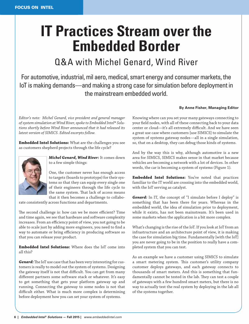
And by the way this is why, although automotive is a new
area for SIMICS, SIMICS makes sense in that market because
vehicles are becoming a network with a lot of devices. In other
words, the car is becoming a system of systems (Figure 1).
Embedded Intel Solutions: You’ve noted that practices
familiar to the IT world are crossing into the embedded world,
with the IoT serving as catalyst.
Genard: In IT, the concept of “I simulate before I deploy” is
something that has been there for years. Whereas in the
embedded world, the idea of simulation prior to deployment,
while it exists, has not been mainstream. It’s been used in
some markets when the application is a bit more complex.
What’s changing is the rise of the IoT. If you look at IoT from an
infrastructure and an architecture point of view, it is making
the case for simulation big time. Fundamentally [with the IoT]
you are never going to be in the position to really have a com-
pleted system that you can test.
As an example we have a customer using SIMICS to simulate
a smart metering system. This customer’s utility company
customer deploys gateways, and each gateway connects to
thousands of smart meters. And this is something that fun-
damentally cannot be tested in the lab. They can test a couple
of gateways with a few hundred smart meters, but there is no
way to actually test the real system by deploying in the lab all
of the systems together.
By Anne Fisher, Managing Editor
IT Practices Stream over the Embedded Border
Q&A with Michel Genard, Wind River
For automotive, industrial, mil aero, medical, smart energy and consumer markets, the IoT is making demands—and making a strong case for simulation before deployment in
the mainstream embedded world.


www.embeddedintel.com | Embedded Intel® Solutions — Fall 2015 | 7
FOCUS ON INTEL
[Without simulation] they would have to test when they deploy,
and this is where there is obviously high cost. What we are seeing
with simulation and SIMICS is that with this kind of opportunity
in the lab you can simulate the full, deployed system, with many
gateways, thousands of smart meters, all embedded devices with
the actual code, that is, with the software that is going to be
deployed and from the software perspective see how the systems
relate. You can force errors, look at “what ifs” and the like.
In the same way that IT has been using virtual machines and
simulation before deployment to manage deployed systems, we
believe that we are going to see the same thing in the IoT world.
Embedded Intel Solutions: What other changes do you see
the IoT bringing?
Genard: One interesting dynamic I am noticing is the question
of “who is going to manage IoT systems?” IoT systems can be con-
sidered an IT system in the sense that it is going to be deployed. So
is it going to be managed by IT people who [traditionally] would
manage a system to be deployed? Yet the point about an IoT
system is that you deploy and you push update features and use
cases all the time—so by definition it is never going to be done.
The IoT is really going to change not only how the company and
users are thinking about the development of systems, it is also
going to change how you think about the deployment of systems
and there is a lot that can be learned from the IT world here.
Embedded Intel Solutions: How do you balance conveying
that the world has changed and at the same time communicating
what you want embedded developers to know about specific Wind
River offerings?
Genard: Welcome to my world. It is always a balancing act,
indeed. An engineer needs to connect to: “I have a job to do; I
have a task to accomplish—what are the roadblocks and how can
I find a solution to work through the roadblocks?” There is a use
case focus. Engaging with an engineer is about focus on the pain
points, on the things that hurt his or her success.
IoT’s advent tips the scales toward management discussions
where the emphasis is: what is going to happen in three to five
years. This is where we offer perspective: knowing that because a,
b, c and d are going to happen, “e” is going to happen, and here are
the steps to take to succeed.
Embedded Intel Solutions: What messages are you most
concerned about getting across?
Genard: When I meet with customers, the one thing I hope will
resonate with them is really around the idea that it is no longer
about trying to put more people on the job, or using people for
offshore development or trying to find the new debugger that will
“by magic” find all the problems that you have not found for years.
Using simulation and tools like SIMICS will help customers think
about how they can transform and how they can come back with
a new way of doing things. You cannot deploy those complex sys-
tems that will be deployed in the IoT world in the same way that
we used to develop 16- or 32-bit systems four or five years ago—it
does not scale.
This is what I spend time on: helping the customer to think differ-
ently, rather than to think, “I need an engineer cheaper that can
do more things,” or “I need a better debugger.” The industry has
been working on debuggers forever.
Figure 1: Today’s passenger vehicles are but one example of the systems of systems that are helping accelerate the migration of IT practices such as simulation before deployment into the embedded world. Photo courtesy Wind River.

8 | Embedded Intel® Solutions — Fall 2015 | www.embeddedintel.com
SP
EC
IAL
FEA
TU
RE
WIR
ELE
SS
& N
ET
WO
RK
ING
Would you be willing to walk away from $1.5 trillion in market
potential? McKinsey & Company recently published a report
on the total potential value of the Internet of Things (IoT),
projecting it could reach $3.9 trillion or higher by 2025. But
there’s a catch—40 percent of that value is dependent on
interoperability between technologies and applications, up to
60 percent in some cases. If this is true, then failing to solve
the sticky issues around interoperability for IoT could result in
a minimum of $1.5 trillion in lost value per year.
In many cases, there could be more than money on the table.
Much of the value in IoT solutions lies in less tangible—but
no less important—benefits, like faster notifications and
responses to emergency situations such as pipeline leaks,
infrastructure failures, or natural or man-made disasters.
Consider this scenario, based on an everyday occurrence in
most cities—a serious traffic accident toward the end of the
evening rush hour on a major artery. A coordinated IoT-based
response might look like this:
Emergency response teams receive immediate notification
and are routed to the scene automatically, green lighted
along the way
The street lighting level at the accident scene is increased
to assist emergency crews on the scene
Parking restrictions on alternate routes are automatically
extended past rush hour to keep driving lanes open to
cope with extra volume as drivers detour
Transit buses are re-routed and riders receive automatic
notifications to smartphones of alternate stops for their
commute home
A successfully coordinated response to the situation just
described requires interoperable systems. It is highly unlikely
that the traffic management system, the public lighting system,
the emergency dispatch system and the transit routing system
were all procured from the same vendor, but for this to work,
they need to seamlessly share information quickly.
Interoperability and Proprietary SystemsClosed, proprietary systems can make interoperability dif-
ficult. What’s more, the problems extend beyond hindering
interoperability. Making different components and elements
of a system work together when they were not designed to
do so can require a significant investment of time and effort,
increasing the time to deployment and the overall cost.
The temptation is often to enable only what is immediately
needed, to keep costs under control, which means that the
information available may be underused and not well inte-
grated into other systems to which it could add value. But once
deployed, and especially if a system has been in use for several
years, it can be extremely difficult to change anything—the
vendor may no longer be available for support, and finding
developers with the required expertise in proprietary systems
can be difficult and expensive.
While the challenges are certainly significant in a fast-moving,
fragmented industry, there are solutions available, if, as an
industry, we’re willing to work together.
Standards and StakeholdersOne of the ways the interoperability challenge is being
addressed is through collaborative efforts to establish stan-
dards. Thoughtful and collaborative standardization paves the
way for innovation by providing freedom of choice and flex-
ibility—developers can use devices from multiple vendors to
customize a solution to meet their specific needs.
By Larry Zibrik, Sierra Wireless
Open-source: Key to Critical Interoperability in the IoT
Traffic mishaps from the mild to life threatening happen. But coordinating a response to them—and to leveraging the full potential of the IoT for industrial, consumer, mil aero,
smart energy, medical and more—can’t come about “by accident.”

10 | Embedded Intel® Solutions — Fall 2015 | www.embeddedintel.com
SP
EC
IAL
FEA
TU
RE
WIR
ELE
SS
& N
ET
WO
RK
ING
There are two ways this is currently being addressed. One is
through industry standards organizations like oneM2M,
a consortium of industry stakeholders that jointly develop
technical specifications that address the need for a common
M2M Service Layer that can be embedded within various
hardware and software and relied on to connect a wide range of
devices to M2M application servers. The group has published
the oneM2M Release 1 specifications, which are available for
download from www.onem2m.org.
Another complementary approach to standards develop-
ment is the release of designs and specifications developed
by industry ecosystem players into the open source com-
munity as open hardware and interface standards for others
to adopt. As the community develops and each contribution
leads to the next, innovation is accelerated, barriers to entry
are lowered, interoperability becomes easier and everyone
wins. This approach has been gaining ground recently, with
open hardware reference designs and open interface standards
becoming more readily available and major industry players
collaborating to support them, reducing the time and effort
to get prototypes from paper to production by ensuring that
various connectors and sensors work together automatically
with no coding required.
Software’s RoleOn the software side, working with widely supported open
source software application frameworks and development
environments, based on Linux, for example, offers several
benefits. It broadens the community of developers and pro-
tects the time and investment devoted to development by
increasing the longevity of solutions. It also provides a wealth
of resources, including online code libraries and developer
communities, which give IoT application developers a head
start in getting their products to market. One example of this,
Legato embedded platform, developed by Sierra Wireless and
released last year, can be embedded on any application pro-
cessor and simplifies development of IoT applications.
The truth is that none of us can envision every possible appli-
cation for IoT technology. We are committed to an open-source
strategy because we believe that it will drive innovation in
the Internet of Things the way that it has in so many other
areas of technology development, by enabling developers to
get their applications to market faster and easier. It offers far
more flexibility for developers to port their applications, or
even portions of their code, from one device to another and
from one generation to the next. This makes it easier to justify
the development investment and reduces the time and efforts
required, particularly as the ecosystem of developers expands.
And importantly, the use of open source software, open hard-
ware standards and specifications, and industry support for
standardization efforts is crucial toward interoperability and
the value it promises to deliver as the IoT develops.
Larry Zibrik is the vice president of Market
Development for Sierra Wireless, responsible
for developing key ecosystem relationships
with mobile network operators, silicon pro-
viders and solution partners. During his
time at Sierra Wireless, Zibrik has been
responsible for developing the company’s
embedded modules business in both PC
OEM and broadband M2M markets. Prior
to joining Sierra Wireless, Zibrik gained
extensive experience with wireless data and M2M though twelve
years at Motorola Inc., where he managed the Embedded Module
portfolio globally for Motorola’s Wireless Data Group.
Courtesy Wikipedia.org
“…failing to solve the sticky issues around interoperability for IoT could
result in a minimum of $1.5 trillion in lost value per year.”

www.embeddedintel.com | Embedded Intel® Solutions — Fall 2015 | 11
WIR
ELE
SS
& N
ET
WO
RK
ING
SP
EC
IAL F
EA
TU
RE
By Anne Fisher, Managing Editor
A Train Ride, Then Making the Case for Open Standards to Stay on Track
Unwrapping a white paper with GreenPeak Technologies
CEO and founder Cees Links
IoT strategy and the “defined and distinct” jobs ZigBee, WiFi and
Bluetooth should have is one topic covered here.
Editor’s note: Embedded Intel ® Solutions asked Cees Links, CEO and
founder of GreenPeak Technologies, to take us behind the scenes of
“The Power of ZigBee 3.0—All about the new and improved ZigBee
3.0,” a white paper Links authored recently. Edited excerpts follow.
Embedded Intel Solutions: What should the decision maker
who reads the white paper take away?
Cees Links, GreenPeak Technologies:
The key take-away is that ZigBee has
reached the level of maturity necessary to
become a success. WiFi and Bluetooth were
not slam-dunks out of the gate; they took
some time to mature. The same applies
for ZigBee, which resides in an even more
difficult and complex space. But with
ZigBee 3.0, many different and diverse
requirements have been brought together in a homogeneous
way, indicating that prime time for ZigBee has arrived.
Embedded Intel Solutions: Say I am one of the decision
makers who has just given this white paper a couple of careful
readings and I agree with its arguments. What steps should I
take next?
Links: The key step to be taken is to establish ZigBee 3.0 as an
integral technology of the IoT strategy, because it is becoming
the dominant networking technology for sense and control
networking, which means: low-cost ubiquitous chipsets from
multiple vendors, universally available frequency bands and
standard middleware available everywhere, integrated with
application frameworks, etc.
ZigBee 3.0 needs to have a defined and distinct role in any IoT
strategy along with WiFi (for high speed/high data rate network-
ing) and Bluetooth (for wearable connectivity).
Embedded Intel Solutions: Do you anticipate that some
of the individuals who will not agree with the white paper’s
arguments will have stronger counter arguments in some
areas than others?
Links: Some people/companies are taking the position that
WiFi and Bluetooth will do the job, and that ZigBee would not
be required. We think these people/companies are misguided.
WiFi is for content sharing and distribution (high data rate,
high power), ZigBee is for sense and control networking
(low data rate, ultra-long battery life), and as such are very
complementary. Bluetooth is for wearables, close proximity
connectivity: it is the network that connects via your
smartphone to the Internet and that you carry along with you
when you go places.
Embedded Intel Solutions: How did you prepare to write this
white paper—what information did you already “own” and
into what topics did you have to dig deeper while preparing it?
Links: That is a funny question. In general I live and breathe
this stuff. Two decades ago, I was part of the team that initially
developed 802.11, which evolved into WiFi. But to address
the question about preparing “The Power of ZigBee 3.0—All
about the new and improved ZigBee 3.0”: After the last plenary
meeting of the ZigBee Alliance in early June in Cologne, I
got really enthusiastic about seeing so many things coming
together that as an industry group we have been working on
for years—and my thought was: we need to turn this around
into a white paper—because this is all very powerful. So, on
the train ride back, I just banged it out, and after a few edits
and iterations we published it.

12 | Embedded Intel® Solutions — Fall 2015 | www.embeddedintel.com
SP
EC
IAL
FEA
TU
RE
WIR
ELE
SS
& N
ET
WO
RK
ING
Embedded Intel Solutions: Do you have recommendations
for addressing the underlying problem that led first to the
symptom of competing radio technology conflicts a decade ago
and now to the IoT and Smart Home conflicts you mention in
the white paper?
Links: For communication to work, it needs open, worldwide
standards.
In the early days of WiFi, it had to compete with several
proprietary technologies (e.g. HomeRF) that were closed and
not available worldwide (sub-GHz). Similarly, in the early days
of ZigBee it competed with proprietary technologies as well (e.g.
Z-Wave, EnOcean). These proprietary technologies have a head
start, but will soon turn out to be only regionally successful
and expensive.
In the early days of WiFi, it also had to compete with Bluetooth
(which is also an open standard). The reason was that Bluetooth
positioned itself as if it would make WiFi redundant. After a
few years however, it was clear that both WiFi (networking) and
Bluetooth (connectivity) had their own application domains,
and both technologies became very successful building out
their own parallel international ecosystems. Interestingly,
Bluetooth is now claiming that it will make ZigBee redundant.
This will have the same result as with WiFi—both Bluetooth
and ZigBee will end up with their own distinct application
domains, and both will be successful.
Embedded Intel Solutions: What issues are these conflicts
distracting decision makers from and as a result of this
distraction and lack of attention to other issues, what’s going to
suffer now and what’s going to suffer down the road?
Links: The general attitude in the market towards standards
confusion is one of “wait and see.” Standard wars paralyze
decision-making and stall new developing markets. Device
and system makers don’t want to take a chance on spending
time and money developing solutions that may turn out to be a
technology dead end.
That is why these conflicts only yield losers: nobody wins, and
products that can make the difference in people’s lives are just
postponed.
Sometimes technology companies deliberately start standards
wars if they are behind in development, very much along the
lines of: “I am too late, and therefore I cannot win, but by cre-
ating standards confusion, I will also make sure that you cannot
win either.” We see that a little bit with companies today that
have WiFi and Bluetooth, but no ZigBee: these companies are
the major proponents of creating the confusion in the current
standards today.
Embedded Intel Solutions: What were the steps you took to
bring light to this subject as opposed to “winning” for your
side—or can both those things happen at once?
Links: Down the road we expect that common sense will prevail.
There is simply no alternative for ZigBee as a key cornerstone
of the IoT for low-power-sense-and-control networking, and it
makes a lot of sense to see ZigBee next to WiFi and Bluetooth
each with their own application domain.
The key characteristics of communication standards are simple:
(1) they need to be open (low cost, multiple suppliers, peace of
mind) and (2) they need to be available worldwide (one product,
one certification, no different settings per region, no worry).
These requirements sound simple, but in reality they are very
hard to accomplish. However, once they are accomplished, there
is practically speaking, no alternative to eliminating the wait for
real market adoption.
Photo courtesy commons.wikimedia.org


14 | Embedded Intel® Solutions — Fall 2015 | www.embeddedintel.com
SP
EC
IAL
FEA
TU
RE
DIG
ITA
L S
IGN
AG
E &
SM
AR
T D
ISP
LAY
S
By Anne Fisher, Managing Editor
A Separate Place for “What Changes Most” Puts Risk in its PlaceQ&A with American Portwell Technology
Digital signage, automation, healthcare and other applications benefit from a modular architecture’s role in minimizing risk.
Editor’s note: American Portwell Technology, a Premier member of
the Intel® Internet of Things (IoT) Solutions Alliance, has close to
10 years experience offering COM Express products. Frank Shen
is the vice president of product marketing at American Portwell
Technology, and he responded recently to questions from Embedded
Intel ® Solutions about the COM Express form factor, the Industrial
IoT and the need to accommodate change cost effectively. Edited
excerpts follow.
Embedded Intel Solutions: How have you seen the Industrial
Internet of Things change thinking?
Frank Shen, American Portwell Tech-
nology, Inc: The IoT has gradually changed
the industrial user’s mindset on return on
investment, especially for the cases where
an industrial business needs services. For
example, a smart factory management system
could collect data about the robotics used in
factory automation and store that informa-
tion in the cloud. The management system can then analyze the
data, compare it against a failure mode database and mainte-
nance history, and send an alert or notice to the service team if
any critical part is falling closer into failure condition and needs
to be replaced. Or it can indicate when services need to be put in
place to prevent conditions that could lead to unplanned inter-
ruptions in factory operations.
However, IoT projects are different from traditional embedded
computing projects. The key difference is that an IoT project typ-
ically would require more collaboration on the part of different
players in the ecosystem, particularly demanding expertise in
software application and implementation, such as analytics,
connectivity, data security, data storage and project manage-
ment. The market is still in the early stages for Industrial IoT. It’s
going to take vision, ideas and effort on the part of both users
and suppliers to bring the Industrial IoT to greater maturity
over the coming years.
Embedded Intel Solutions: Of course even before the IoT,
change and the need to future proof for change have been
part of the picture. How does your recently announced COM
Express Compact module address this requirement?
Shen: The advantage of the COM Express form factor is how
it separates out the CPU—the portion of the system that
changes most with the market—onto an upgradeable module
and the system-specific I/O onto the carrier board.
Feedback from our customers confirms that this modular
architecture (Figure 1) speeds up their time-to-market for
custom-made applications because it provides them with the
flexibility for functional expansion.
Figure 1: COM Express modular architecture enables upgradability, flexibility, expandability and faster time to market.
www.embeddedintel.com | Embedded Intel® Solutions — Fall 2015 | 15
SP
EC
IAL F
EA
TU
RE
DIG
ITAL S
IGN
AG
E &
SM
AR
T D
ISP
LAY
S
Modular architecture that offers flexibility is integral to, for
example, the PCOM-B633VG COM Express module that Portwell
introduced earlier this year targeting digital signage, healthcare
and retail sectors. And modular architecture is also key to the
company’s recently announced PCOM-B636VG COM Express
module, based on Intel® Celeron® or Pentium® processor N3000
series (codenamed Braswell), put into action in a network appli-
ance platform. When a network appliance has been designed
with an Intel® Atom™ processor-based COM Express module,
the next generation of that appliance can easily upgrade to this
latest COM Express module from Portwell, without having to
change its carrier board design. What’s gained are more pro-
cessor resources and performance for software features, while
the COM Express module consumes the same or even less power
than it did before.
Some of the ways in which we anticipate the module will be used
are, for example, industrial automation, where the module’s
watchdog timer can reset the system and continue the opera-
tion if the system hangs. For medical life science analysis, the
enhanced graphics performance comes into play, and the Intel
Celeron and Intel Pentium processor N3000 series upon which
our COM Express Compact module is based also meets the low
power requirements of thin client systems.
Choosing the COM Express form factor can help minimize
design risks. This approach can also keep development time
and costs in line during the initial phase of development. Faster
time-to-market, a simplified future upgrade path, scalability
and an increased application lifecycle are the results.
Embedded Intel Solutions: Thank you, any closing thoughts?
Shen: Just to emphasize that when you have the flexibility to
upgrade your system without having to change existing carrier
boards and operating systems, you can take advantage of, for
example, USB 3.0, one of the enhanced features supported by
the Braswell architecture over the previous generation entry-
level CPUs, which is 10 times faster than USB 2.0, putting you in
position to benefit from faster response or higher efficiency in
control or communication. And last but not least, Portwell has
accumulated extensive embedded computing and engineering
experience in providing customized COM Express solutions and
module and carrier board design and manufacturing.
“It’s going to take need vision, ideas and effort on the part of both users’ and
suppliers to bring the Industrial IoT to greater maturity over the coming years.”
Visitwww.embeddedintel.com
Subscribe Today atwww.embeddedintel.com
Free!
S
Gold Sponsors
Spring 2015
Right Sizing
Your Embedded
Application
Smart Fabric, Not Wrist
Bling, To Lead Wearable
Market Growth?
www.embeddedintel.com
Industrial IoT Looks
to SMARC
bscribe Today at
Gold Sponsors
Summer 2015
Gold Sponsors
www.embeddedintel.com
A Lightbulb Moment for Wearable Technology
IoT Brings Greenfield Opportunity
LAN Bypass for More Robust Networks
Visit
Designing with Intel® Embedded
Processors?
Embedded Intel® Solutions delivers in-depth product, technology and design information to engineers
and embedded developers who design with Intel® Embedded processors

16 | Embedded Intel® Solutions — Fall 2015 | www.embeddedintel.com
SP
EC
IAL
FEA
TU
RE
DIG
ITA
L S
IGN
AG
E &
SM
AR
T D
ISP
LAY
S
By Anne Fisher, Managing Editor
Digital Signage Makes Fast Work of Integration with OPS Fast Tracking
Q&A with Bill Lee, Axiomtek
Global perspective on the digital signage market, the impact of Intel’s Open
Pluggable Specification (OPS), the IoT’s role and more.
Editor’s note: Axiomtek’s Bill Lee is North American product man-
ager, responsible for the company’s digital signage and embedded
panel PC product lines. Lee spoke with EECatalog recently about
topics including the impact the Internet of Things (IoT) has made
on the digital signage market, the key role a vendor’s ability to
offer services plays—Axiomtek offers a full gamut, from hardware
customization to configuring for memory capacity to integrating
customer software— and understanding what’s involved in cal-
culating Total Cost of Ownership (TCO). Edited excerpts of the
conversation follow.
Embedded Intel Solutions: How did Intel®’s introduction of
the Open Pluggable Specification (OPS) make a difference?
Bill Lee, Axiomtek: Before OPS was
introduced, most digital signage sys-
tems consisted of a single computer or
player with a monitor or were comprised
of a monitor that incorporated a com-
puter that could not be removed easily.
With the introduction of OPS, outside
the traditional “one computer to one dis-
play with a functional cable between the
two” paradigm, came easier installation, easier maintenance
and faster time to market. Customers want the clean instal-
lation made possible by the OPS architecture and the ease of
switching out the computer player.
Intel has been a big influencer in the digital signage industry.
They were in the right position at the time to set and promote
a standard. There were some pluggable specifications from
display companies like NEC and computer manufacturers like
Axiomtek, but the specifications were not widely adapted.
Customers wanted easy installation process without compat-
ibility issues between all components especially the display
and the pluggable digital signage player. Intel® standard has
made it possible to ensure seamless integration and, through
the simplified OPS architecture, allowing the customers to
switch out/upgrade/maintain the computer player with ease.
Embedded Intel Solutions: What’s the extent of Axiomtek’s
involvement with OPS?
Lee: We followed Intel’s OPS spec from the very beginning.
The Intel team that developed the specification consulted with
Axiomtek at our headquarters in Taiwan because we had the
experience of having developed a pluggable specification. We
worked closely with Intel on planning the specification itself
and on following it to make our own OPS module. So begin-
ning with 2nd generation Intel® Core™ processors, which was
when the OPS spec was introduced, we have continued on to
products based on the 4th generation Intel Core microarchi-
tecture (Figure 1).
Embedded Intel Solutions: Why did you move to the Intel
desktop platform? 4th Generation Intel Core i7/i5/i3 & Intel®
Celeron® processors.
Lee: All other vendors of OPS systems base them on Intel’s
mobile platform, which means lower power requirements. How-
ever, because Intel’s strategy is that mobile processors have to
be soldered onto the motherboard starting from the 4th Gener-
ation Intel Core processors, this makes it difficult for customers
to configure the system according to their needs. Moving to the
Figure 1: The Axiomtek OPS883 comes equipped with a choice of 4th Generation Intel® Core™ processors (i7/i5/i3) or Intel® Cel-eron® processor. It supports dual display and 4K resolution. It also supports DDR3 SO-DIMM memory with up to 8GB and offers one PCI Express Mini Card slot for connectivity.

www.embeddedintel.com | Embedded Intel® Solutions — Fall 2015 | 17
SP
EC
IAL F
EA
TU
RE
DIG
ITAL S
IGN
AG
E &
SM
AR
T D
ISP
LAY
S
Intel desktop platform bypasses the soldered on CPU, allowing
for flexibility in configuration. It enables customers to choose
the CPU that will suit their requirements—4th Generation
Intel Core i3/ i5/i 7 processors or Intel Celeron® processors.
This approach also makes it easier for customers to scale the
deployment of their digital signage systems and to satisfy the
requirements of the various operations where the signage is
deployed. And because desktop processors generally cost less
than mobile processors, this lowers the cost-performance ratio.
Embedded Intel Solutions: Beyond just supplying hardware,
Axiomtek also offers design engineering services. What chal-
lenges are these engineers encountering?
Lee: One challenge is the compatibility issue between the OPS
and the display. We come across cases, where, for example, the
display does not show anything from the OPS player or the
display cannot power up the OPS player.
We ensure compatibility in two ways. One, we test and adjust
our OPS player to work with the display the customer selected.
Two, if we find incompatibility issues that cannot be adjusted
on our end, we will work with the display vendor closely until
the issue is resolved. On many occasions, our troubleshooting
steps involve getting down to board level within the display
unit to diagnose the problems and provide viable recommen-
dations for corrections.
As a part of our standard operating procedure, we do strict
verification tests on our designs. For example, we check that
all the signals from the ports are compliant with the stan-
dard. Another example of our verification tests involves the
use of our OPS player in harsh operating environments. The
OPS players could be used in an indoor environment in which
the temperature rises to 100 degrees F., perhaps as a factor of
clustering systems closely together. We do make sure that our
players can endure that environment. We have a temperature
testing chamber that allows us to check for reliability in an
extended temperature operation.
Embedded Intel Solutions: What trends and differences are
you observing in the digital signage sector?
Lee: An approach in which cost is the driving factor is promi-
nent in the North American region, a trend that differs from
attitudes in Europe and Asia. Other parts of the world have
already gone through the phase of thinking they could get by
with consumer type digital signage systems for commercial
use and are now turning to more reliable systems.
Figure 2: Large screen displays are being used to replace traditional whiteboards and touch screens to allow students to interact with the content on the screen. In a corporate environment, digital white-boards bridge the communication gap and allow for effective remote interactions between staff members and clients in meetings.
Digital signage in the U.S. has started later than in other areas
of the world, and there are customer requests that tend to
favor budget over product quality and reliability, reflecting a
belief that digital signage equipment costs should be similar
to that of a television or a very low-cost computer—with less
thought given to the reliability of the digital signage player
operation and the product’s longevity.
Deployments made with an eye toward low cost rather than
quality may be okay in the short run, but after two years,
the system will begin to need repair and maintenance more
frequently. The cost of repair and operational downtime will
most likely be more than the cost to purchase a higher quality
OPS product to begin with. A more reliable ruggedized solu-
tion will ensure dependability from the very beginning.
A focus just on initial cost is a mistake. It is better to consider
all the elements of Total Cost of Ownership, including main-
tenance, downtime and the replacement costs of the systems
that failed.

18 | Embedded Intel® Solutions — Fall 2015 | www.embeddedintel.com
SP
EC
IAL
FEA
TU
RE
IND
US
TR
IAL
CO
MP
UT
ING
The heart of a microserver is the System-on-Chip processor, an
integrated design that combines a lightweight CPU, memory
controller, I/O controller and sometimes even networking
components into a compact package. Compared to traditional
desktop or laptop processors, the integrated design of SoC
chips generally means less powerful individual components but
enhanced power efficiency and lower system costs.
The space, cost and power savings of SoCs was originally targeted
at the mobile market for smartphones, tablets, netbooks and
embedded systems, but Intel shook things up in 2012 with the
introduction of the Intel® Atom™ processor S1200 product family
(formerly Centerton), targeted towards server applications. Intel
started with the ultra power-efficient base of the Intel Atom
processor design and added enterprise server features including
ECC-memory support for stability, 64-bit processing, out of band
management, and virtualization support in hardware.
The idea of low-power, precisely sized servers turned the tradi-
tional idea of a virtualized data center on its head. Instead of
dealing with increased workloads by provisioning additional
virtual machines, businesses would provision lightweight
physical servers.
Why not Virtualize?Traditional servers with high-end processors, memory, and
storage components are overpowered and underutilized by
many individual business applications, especially more light-
weight services such as email, file or print share, and web
hosting. The traditional approach to optimize these underuti-
lized servers has been virtualization. By allocating multiple
virtual machines on a single server, computing resources can be
efficiently allocated to make best use of the hardware.
While virtualization makes the most of existing server hard-
ware, it may not be the best method for all server workloads.
Servers built for virtualization tend to be big, beefy all-pur-
pose machines ready for a diverse range of workloads. These
supermachines may be capable of running any and everything,
but their very nature means they’re overpowered for many of
the tasks they end up performing.
Microservers take the opposite approach. By sizing the hardware
to compute needs, power usage is optimized for more lightweight
workloads. If the same application can be effectively served by a
20W, 10W, or 6W TDP processor, using an 80W TDP CPU is inher-
ently inefficient no matter how well you virtualize.
Microservers also create efficiency as they can be sized more
precisely for the workload while still providing redundancy.
Traditional servers need to have more computational capacity
than needed to provide room for expansion. When workloads
increase beyond capacity, additional, expensive server hardware
needs to be bought, which is again underutilized until the work-
load grows to meet capacity.
With the low costs of individual microservers, initial server
purchases can be sized more precisely and as workload
increases, additional physical microservers can be easily and
economically added to meet demands, creating efficient and
economical scalability. With more physical servers handling
workloads, microservers can also be more robust than virtualized
infrastructure with fewer servers. When one microserver out of
a 10 or 40 microserver
cluster goes down, the
impact is minimal,
whereas if a traditional
server with 10 or 40 vir-
tual machines goes down,
all of the virtual machines
and the services running
on them are impacted.
From Wimpy to BrawnyWhen the idea of
microservers was first
popularized in 2012 with
the introduction of the
Intel Atom processor S1200 product family, the server features
were there, but relatively low clock speeds, an 8GB memory limit,
and weak single-thread performance of those first generation
chips kept the industry skeptical.
In 2013, Intel announced the Intel Atom C2000 series of SoC chips
targeted towards servers. Based on 22nm lithography, the C2000
series (formerly Avoton) brought some power to S1200 series pro-
cessors with up to 8 cores with 4 threads each, clock speeds up to
2.4GHz and 64GB of maximum memory. This new generation of
server-focused processors delivered enough processing power to
serve not just static but also dynamic web content.
By Dan Zhang, Technical Contributor
Microservers: Pint-Sized Machines Making a Big Impact
SoC processors faithful to an ultra-low-power diet are getting in vigorous workouts as well, gaining traction as CPUs for data center application servers, but
are their cores athletic enough?
Figure 1: Microservers are well suited to low-end workloads that scale well with more compute nodes.

www.embeddedintel.com | Embedded Intel® Solutions — Fall 2015 | 19
SP
EC
IAL F
EA
TU
RE
IND
US
TR
IAL C
OM
PU
TIN
G
Besides more muscle, the processor C2000 series brought more
integration and power efficiency to the Intel Atom processor
platform, adding SATA and Ethernet controllers in addition
to the memory and IO controllers already present in the S1200
series. With all this functionality in the chip itself, even though
the TDPs from 6W to 20W were on average higher than with the
S1200 series, performance per watt was much better. This more
comprehensive SoC design made it easier for system integrators
to create extremely compact and power efficient designs.
As mobile derived SoCs move further up-market to invade the
server space, heavy-duty server chips are slimming down and
moving into the microserver space. In May 2015, Intel announced
the Intel® Xeon® processor D family, a totally new server chip
design that combines the latest 14nm Intel® Core™ M processors
with an integrated SoC design for an ultra-low-power Intel Xeon
processor for lightweight, scale-out workloads. According to Intel,
the new chips “deliver up to 3.4x faster performance per node
and up to 1.7x better performance per watt when compared to
the Intel Atom processor C2750.” Also known as Broadwell-DE,
the new Intel Xeon processor D-1520 and D-1540 chips run at
45W TDP, more than Avoton, but at less than half of the power
consumed by most server-class Intel Xeon processors. (Wattage
figures include all the memory, networking and I/O features that
would normally take up extra chips or cards on a regular server-
class Xeon). That enables the new Intel Xeon processor D family to
create some of the most power-efficient server motherboards on
the market. With prices starting right above the feature rich Intel
Atom processor C2750, these are aimed squarely at the upper end
of the microserver market where the Avoton leaves off.
Besides beefing up processing power, the new generation of
SoC chips increased memory capacity and has also made a
huge difference in server performance. Compared to mobile
or desktop applications, servers are much more memory con-
strained as they’re running more processes for more users at
any given time. Whereas Centerton-era processors could only
handle 8GB, the Intel Atom processor C2000 series can handle
up to 64GB of DDR3 ECC or non-ECC memory at 1600 MHz.
The Intel Xeon D family supports DDR4 and can take 128GB of
ECC/non-ECC or 256GB of Registered Memory. Key “coaches”
in the corner for helping SoC based servers go toe to toe with
their bigger cousins and replace larger machines on a wider
range of workloads are 16GB DDR3 modules from manufac-
turers including Innodisk (Figure 2).
Micro Server or Microserver?The server-class features enabled by the new generation of SoC
processors are making a big impact on two ends of the business
server market. Small businesses have not previously been able
to afford the costs of buying or running dedicated rackmount or
tower servers. At the opposite end of the spectrum, large-scale
cloud-based enterprises are finding relief from the spiraling data
center costs while their businesses expand.
The Small Business Micro ServerIntel’s move into low-power server processors has opened
a new market in the small business segment by powering
a diminutive class of affordable, space saving SMB servers
known colloquially as “Micro Servers.”
The Micro Server is based on an SoC server chip and has
enterprise server features such as ECC memory and hardware
virtualization, yet is priced on par with a desktop PC. Using
power saving SoC processors, these machines often run under
100W and can go as low as 20W—not much more than the LCD
monitors they’re attached to.
For small businesses this has been a revelation. Businesses that
couldn’t afford the costs of buying and running full-fledged
rackmount, pedestal or tower servers can now consider a Micro
Server for their small business needs. Compared to allocating
virtual machines on traditional servers, these affordable micro
servers are easier for small businesses to set up properly without
the complexity of dealing with rackmount infrastructure and
virtualization. Lower upfront and running costs make it easy
for businesses to buy machines as needed instead of having to
make big budget decisions upfront and each time workloads
expand beyond server capacity.
While Centerton-based Micro Servers were suited to a few limited
lightweight applications, the current Intel Atom processor C2000
series-based Micro Servers and upcoming Intel Xeon D processor-
based processor-based machines have enabled Micro Servers with
enough juice and the server-sized memory capacity to take on a
much more diverse range of small business workloads.
Enterprise Microserver ClustersAs the power of Intel Atom processor and similar SoC processors
grows, their capability has been recognized in the enterprise server
space. Computationally light, easily parallelized workloads such as
web hosting and content delivery underutilize the processing power
of full-strength server processors but are well suited to the light-
weight, scalable nature of microservers. While traditional servers
can and do take on these tasks, the power efficiency of microservers
and their ability to incrementally grow to business needs by adding
physical machines is especially attractive to these types of industries.
Rather than the independent “Micro Server” machines used in
small businesses, microservers in these enterprise contexts are
usually compact server boards clustered inside rackmount chas-
sis to simplify management and consolidate cooling, power and
networking infrastructure.
Dan Zhang is a technical contributor for
EECatalog. He has worked previously as an
Enterprise IT Consultant with IBM, Lenovo and
The World Bank and holds a bachelors degree
in computer engineering from the University of
Maryland.
Figure 2: 16GB DDR3 modules like this 1600Hz model from Innodisk help maximize memory capacity and performance for servers based on the Intel Atom processor C2000 SoC.

20 | Embedded Intel® Solutions — Fall 2015 | www.embeddedintel.com
SP
EC
IAL
FEA
TU
RE
IND
US
TR
IAL
CO
MP
UT
ING
By Dan Demers, congatec
Energy Thief Hunter Relies on COM Express
Success Story: Intel® Core™ i5 processor powers a COM Express computer module, improving measurement speed and quality for power analyzer.
Currently, motors and drives consume up to 45 percent of
electrical energy, so it makes sense to track down any potential
sources of energy loss. That is certainly the view of ZES
ZIMMER Electronic Systems GmbH, a maker of high-precision
power analysis products. The company’s Smart Power Analyzer
LMG670 helps engineers optimize power consumption by
incorporating DualPath technology to improve measurement
quality and speed. To manage these required performance
improvements, the system design was transformed from
FPGA to x86 and is now powered by a COM Express computer
module with an Intel ® Core ™ i5 processor (Figure 1).
Power measurement looks at both the accuracy as well as the
efficiency of the entire energy distribution chain or that of its
individual parts. A frequency inverter manufacturer uses it to
ensure the company’s products are as efficient as possible. At
higher switching frequencies, the reproduction of sine waves
is better, however at the same time switching losses in the
inverter increase, and engineers seek the correct balance.
An engine manufacturer, on the other hand, wants to convert
as much energy into mechanical power as possible; this
requires a clean sinusoidal current. Optimizing the frequency
inverter may in some cases decrease the engine’s efficiency.
Ultimately, a washing machine manufacturer not only wants
a fast rotating drum but one that does not vibrate during the
spin cycle. And the objective in this case is also a powerful yet
energy-efficient motor. Answers to questions including, “ how
big are the losses in the overall system, where do they occur
and how can the best result be achieved,” can only be found
when we analyze all the parts involved and examine how well
they play together.
Signal Conditioning—But How?Two measurement methods are required to best fine-tune the
inverter and motor: An unfiltered signal for determining the
overall power consumption, which is particularly important
when trying to determine efficiency; and the filtered signal
for the analysis of specific areas. This begs the question: “how
to prepare the signal?” Should we filter the signal to cut the
frequency band at the top, thereby complying with the rules
of the Shannon-Nyquist theorem? This results in considerable
inaccuracies in the power measurements. Or should we filter
the unfiltered signal retrospectively to pick out the desired
frequencies? While this approach looks interesting at first
glance, it is unfortunately not permitted as the aliasing errors
already affected the signal during the preceding sampling
process, and they cannot be removed.
Until now, there were two ways to make these two measurements:
First, you could use two independent measurement
instruments to analyze the signal. The connection of this
second device might cause errors in measurements due to
differences in cable lengths, terminal resistances or parasitic
capacitances. Alternatively, you could repeat the measurement
with the same device but change the filter settings. In this
case, it was necessary to ensure that the exact same signal was
measured under exactly the same environmental conditions
Figure 1: A COM Express computer module powers the ZES Zimmer Precision Power Analyzer LMG670.
“To achieve this demanded performance increase, ZES Zimmer switched from an FPGA-based approach to x86 processor technology.”
www.embeddedintel.com | Embedded Intel® Solutions — Fall 2015 | 21
SP
EC
IAL F
EA
TU
RE
IND
US
TR
IAL C
OM
PU
TIN
G
during the second test. To achieve this, the motor had to
cool down before the second measurement to get the same
starting temperature. So there had to be a certain time
lapse between measurements, as thermal effects would
otherwise degrade the measurement to a mere ballpark
figure. The serial approach is therefore slow; parallel
measurements with two devices involve other sources of
error.
Simultaneous Measurement in Two Bandwidths ZES Zimmer has developed a completely new process
to solve the two-measurement dilemma just described.
The LMG670 precision power analyzer uses a DualPath
architecture to process a signal. The crucial difference
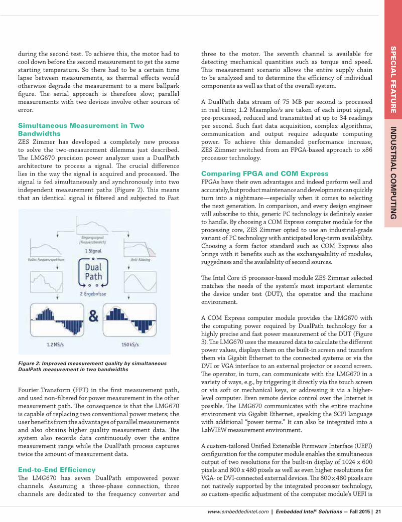
lies in the way the signal is acquired and processed. The
signal is fed simultaneously and synchronously into two
independent measurement paths (Figure 2). This means
that an identical signal is filtered and subjected to Fast
Fourier Transform (FFT) in the first measurement path,
and used non-filtered for power measurement in the other
measurement path. The consequence is that the LMG670
is capable of replacing two conventional power meters; the
user benefits from the advantages of parallel measurements
and also obtains higher quality measurement data. The
system also records data continuously over the entire
measurement range while the DualPath process captures
twice the amount of measurement data.
End-to-End EfficiencyThe LMG670 has seven DualPath empowered power
channels. Assuming a three-phase connection, three
channels are dedicated to the frequency converter and
three to the motor. The seventh channel is available for
detecting mechanical quantities such as torque and speed.
This measurement scenario allows the entire supply chain
to be analyzed and to determine the efficiency of individual
components as well as that of the overall system.
A DualPath data stream of 75 MB per second is processed
in real time; 1.2 Msamples/s are taken of each input signal,
pre-processed, reduced and transmitted at up to 34 readings
per second. Such fast data acquisition, complex algorithms,
communication and output require adequate computing
power. To achieve this demanded performance increase,
ZES Zimmer switched from an FPGA-based approach to x86
processor technology.
Comparing FPGA and COM Express FPGAs have their own advantages and indeed perform well and
accurately, but product maintenance and development can quickly
turn into a nightmare—especially when it comes to selecting
the next generation. In comparison, and every design engineer
will subscribe to this, generic PC technology is definitely easier
to handle. By choosing a COM Express computer module for the
processing core, ZES Zimmer opted to use an industrial-grade
variant of PC technology with anticipated long-term availability.
Choosing a form factor standard such as COM Express also
brings with it benefits such as the exchangeability of modules,
ruggedness and the availability of second sources.
The Intel Core i5 processor-based module ZES Zimmer selected
matches the needs of the system’s most important elements:
the device under test (DUT), the operator and the machine
environment.
A COM Express computer module provides the LMG670 with
the computing power required by DualPath technology for a
highly precise and fast power measurement of the DUT (Figure
3). The LMG670 uses the measured data to calculate the different
power values, displays them on the built-in screen and transfers
them via Gigabit Ethernet to the connected systems or via the
DVI or VGA interface to an external projector or second screen.
The operator, in turn, can communicate with the LMG670 in a
variety of ways, e.g., by triggering it directly via the touch screen
or via soft or mechanical keys, or addressing it via a higher-
level computer. Even remote device control over the Internet is
possible. The LMG670 communicates with the entire machine
environment via Gigabit Ethernet, speaking the SCPI language
with additional “power terms.” It can also be integrated into a
LabVIEW measurement environment.
A custom-tailored Unified Extensible Firmware Interface (UEFI)
configuration for the computer module enables the simultaneous
output of two resolutions for the built-in display of 1024 x 600
pixels and 800 x 480 pixels as well as even higher resolutions for
VGA- or DVI-connected external devices. The 800 x 480 pixels are
not natively supported by the integrated processor technology,
so custom-specific adjustment of the computer module’s UEFI is
Figure 2: Improved measurement quality by simultaneous DualPath measurement in two bandwidths
22 | Embedded Intel® Solutions — Fall 2015 | www.embeddedintel.com
SP
EC
IAL
FEA
TU
RE
IND
US
TR
IAL
CO
MP
UT
ING
required. To meet this requirement, ZES Zimmer needed to work
with a service-focused computer module vendor that could offer
UEFI adaptations via individual integration services.
The decision to go with a module vendor with a clearly defined,
easy process providing barrier-free personal access to the OS and
firmware specialists proved to be a good choice for the application
engineers and the entire engineering process, as they not only
had to integrate the DualPath technology, but also to migrate the
design from FPGA to x86.
In and of itself, a form factor standard is not a differentiator.
It’s standardized and consequently easily substitutable. What
truly matters to the successful implementation of a COM
module depends more on details such as the supplied firmware,
software, operating system adaptations for embedded
purposes and especially the individual and personalized
design-in support.
Standard Form Factors—What CountsThe support described above is crucial
for many designers of industrial-grade
systems—FPGA engineers need to manage
a learning curve for x86 designs, and many
x86 applications in the embedded area have
their own peculiarities and need specific
tweaks. In addition, a number of applications
still work with legacy serial interfaces, Super
I/O, disabled USB interfaces, custom-specific
animated boot screens or even individual boot
orders of the integrated devices up to booting
via IoT cloud servers. Finally, nearly all new
processors have their own “specialities,”
too. Consequently, OEM customers choose
their embedded vendor with ever more
care, especially with an eye to support—not
only on the hardware side but increasingly
regarding firmware implementations and
driver support.
Dan Demers is director of marketing for the Americas at congatec
Inc. He holds a B.B.A. degree in International Business from
Grand Valley State University, Grand Rap-
ids, Michigan and an M.B.A. from Ashford
University, Clinton, Iowa. Demers has over
13 years of experience in embedded com-
puting having worked with Fortune 500
companies in the medical, military, and
communications markets.
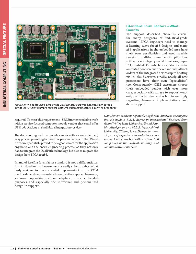
Figure 3: The computing core of the ZES Zimmer’s power analyzer: congatec’s conga-BS77 COM Express module with 3rd generation Intel® Core™ i5 processor

www.embeddedintel.com | Embedded Intel® Solutions — Fall 2015 | 23
SP
EC
IAL F
EA
TU
RE
IND
US
TR
IAL C
OM
PU
TIN
G
By Barbara Schmitz, CMO, MEN Mikro Elektronik
Simplicity Reigns Supreme in CompactPCI Serial Rev 2
Why CompactPCI (PICMG 2.0) is at home in markets from telecom and computer telephony to industrial, real-time
data acquisition, transportation and mil-aero
It’s no wonder CompactPCI systems have proliferated as much
as they have in the past few decades. Built using standard
components, they can run practically any operating system
as well as thousands of application software packages without
modification.
CompactPCI (PICMG 2.0) is a widely accepted—and utilized—
technology platform that has found a home in countless
markets from telecommunications and computer telephony to
industrial automation, real-time data acquisition and military
systems.
However, as data requirements in embedded systems began
to increase, older systems were unable to take advantage
of the more modern high-speed serial point-to-point
communications needed to move all system information along
effectively.
System Demands GrowCompactPCI systems were limited to a parallel bus design, yet
demands for greater bandwidth and higher data transfer rates
among the input/output (I/O) resources continued to increase.
Looking to keep pace with today’s computing needs and
keep a widely implemented successful technology current,
CompactPCI PlusIO (PICMG 2.30) and CompactPCI Serial
(PICMG CPCI-S.0) arrived. Now a defined migration path
using these complementary platforms is demonstrating its
effectiveness as a solid, cost-effective, long-term solution,
positioning CompactPCI as a viable platform for applications
well into the future.
Several years after being introduced, this family of
specifications has proven successful in bringing systems in
line with current data requirements, while preserving two
vital pieces of the embedded computing industry:
A countless number of installed CompactPCI-based
systems
The large knowledge base of designers already familiar
with CompactPCI.
But building upon CompactPCI’s large installed base and the
design knowledge bank is just the start. Since its introduction
four years ago, CompactPCI Serial has been installed in tens
of thousands of applications in existing markets as well as
new ones. And product development has kept pace with the
increasing use of the new specification (Figure 1).
Linking Past and PresentCompactPCI PlusIO does not require systems to switch
boards, and the high-speed connector is low-cost, creating
cost efficiency. Designed for applications with mixed parallel
and serial communication requirements, CompactPCI PlusIO
system slot boards can be used in both CompactPCI and hybrid
systems with CompactPCI Serial peripheral slot boards.
It was deliberately developed using the same 19” mechanics as
legacy CompactPCI, while allowing for the integration of serial
based systems. This very calculated adaptation of the original
specification addresses the challenges of maintaining existing
systems, and therefore the time and money invested in those
systems. It also preserved the reliability, robustness and
maintenance-friendly attributes of the original CompactPCI.
Figure 1: As the CompactPCI Serial specification has evolved, so have available products with enhanced technologies, like this 3U Com-pactPCI Serial SBC based on the fourth generation Intel Core i7.

24 | Embedded Intel® Solutions — Fall 2015 | www.embeddedintel.com
SP
EC
IAL
FEA
TU
RE
IND
US
TR
IAL
CO
MP
UT
ING
While compatible with CompactPCI PlusIO, CompactPCI
Serial is geared towards completely new systems based solely
on serial communications. But because of the link through the
CompactPCI PlusIO structure, older systems can implement
serial technologies on an as needed basis —whether driven by
functionality requirements or budgetary considerations.
CompactPCI Serial is mechanically based on the IEEE 1101
standard, the standard for 19-inch systems and Eurocards,
making mezzanine modules developed for these types of
boards also compatible with CompactPCI Serial. This is
particularly important for backwards compatibility to existing
solutions.
The most important types of such mezzanines are PMCs,
XMCs and M-Modules, all of which fit on Eurocards. In
general, a single Eurocard can accommodate one PMC/XMC or
one M-Module, while a double Eurocard can carry two PMCs or
XMCs, or four M-Modules.
CompactPCI Revisions’ Dual FocusThe revisions to the CompactPCI Serial standard, the first
since the specification was introduced in 2011, focus on two
key areas: simplifying the specification language and building
out some of the technology features.
A page-by-page rework aimed at improving the platform’s
usability has resulted in clearer wording that more sharply
defines the scope of the specification. For example, the
explanation of the order of components in the system takes
compatibility into account.
The content itself has not changed, just the language designers
rely on to easily implement these highly flexible, cost-effective
systems. CompactPCI Serial is a homogenous standard with
continuous compatibility—clear, practicable and user-
friendly. Revision 2 is backward compatible with Revision 1
(Table 1).
Two Improvements Expand System Slot FunctionsThe new revision contains two technical improvements that
expand the functions of the system slot, allowing for more
flexibility within an application. One, the system slot can
now be placed on either the left or right side of the backplane,
offering system designers greater physical layout flexibility.
Two, the system slot now supports additional rear I/O on the
P6 connector, key for conductive cooling systems that usually
do not support front I/O.
Because the rear I/O signals are not fixed, configuring different
combinations of signals is easily achieved, such as routing
graphics and USB outputs to the rear and/or with SATA disks
installed inside the system. And with PCI Express now available
at the rear, several 19” systems can be interconnected.
Ethernet on the Rear I/O Already defined within CompactPCI Serial Rev. 1 is a special
feature that makes it possible for connector P6 to reside
directly on the mezzanine board, not on the CPU board.
CompactPCI Serial Rev. 2 now defines Ethernet on the rear I/O
for the system slot on the P6 connector, bringing with it many
important advantages, as shown in Figure 2.
When using an Ethernet mezzanine
board, the signals are led directly to
the backplane and do not have to be
routed over the carrier board.
Designers have a flexible number of
Ethernet channels via the mezzanine
board. The requirements can vary
greatly, depending on the application,
but a standard CPU card can always be
used.
The combination of rear I/O on P6
with any number of Ethernet channels
via the Ethernet mezzanine board
further adds to the final system‘s
configuration and flexibility.
Table 1: Family of CompactPCI specifications overview
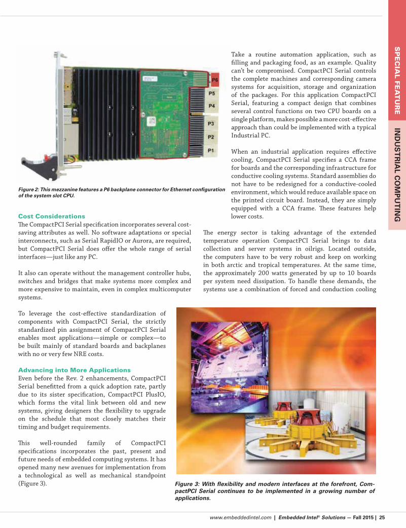
www.embeddedintel.com | Embedded Intel® Solutions — Fall 2015 | 25
SP
EC
IAL F
EA
TU
RE
IND
US
TR
IAL C
OM
PU
TIN
GCost ConsiderationsThe CompactPCI Serial specification incorporates several cost-
saving attributes as well. No software adaptations or special
interconnects, such as Serial RapidIO or Aurora, are required,
but CompactPCI Serial does offer the whole range of serial
interfaces—just like any PC.
It also can operate without the management controller hubs,
switches and bridges that make systems more complex and
more expensive to maintain, even in complex multicomputer
systems.
To leverage the cost-effective standardization of
components with CompactPCI Serial, the strictly
standardized pin assignment of CompactPCI Serial
enables most applications—simple or complex—to
be built mainly of standard boards and backplanes
with no or very few NRE costs.
Advancing into More ApplicationsEven before the Rev. 2 enhancements, CompactPCI
Serial benefitted from a quick adoption rate, partly
due to its sister specification, CompactPCI PlusIO,
which forms the vital link between old and new
systems, giving designers the flexibility to upgrade
on the schedule that most closely matches their
timing and budget requirements.
This well-rounded family of CompactPCI
specifications incorporates the past, present and
future needs of embedded computing systems. It has
opened many new avenues for implementation from
a technological as well as mechanical standpoint
(Figure 3).
Take a routine automation application, such as
filling and packaging food, as an example. Quality
can’t be compromised. CompactPCI Serial controls
the complete machines and corresponding camera
systems for acquisition, storage and organization
of the packages. For this application CompactPCI
Serial, featuring a compact design that combines
several control functions on two CPU boards on a
single platform, makes possible a more cost-effective
approach than could be implemented with a typical
Industrial PC.
When an industrial application requires effective
cooling, CompactPCI Serial specifies a CCA frame
for boards and the corresponding infrastructure for
conductive cooling systems. Standard assemblies do
not have to be redesigned for a conductive-cooled
environment, which would reduce available space on
the printed circuit board. Instead, they are simply
equipped with a CCA frame. These features help
lower costs.
The energy sector is taking advantage of the extended
temperature operation CompactPCI Serial brings to data
collection and server systems in oilrigs. Located outside,
the computers have to be very robust and keep on working
in both arctic and tropical temperatures. At the same time,
the approximately 200 watts generated by up to 10 boards
per system need dissipation. To handle these demands, the
systems use a combination of forced and conduction cooling
Figure 2: This mezzanine features a P6 backplane connector for Ethernet configuration of the system slot CPU.
Figure 3: With flexibility and modern interfaces at the forefront, Com-pactPCI Serial continues to be implemented in a growing number of applications.

26 | Embedded Intel® Solutions — Fall 2015 | www.embeddedintel.com
SP
EC
IAL
FEA
TU
RE
IND
US
TR
IAL
CO
MP
UT
ING
on a compact system, which combines four computer units in
one system.
Public transportation, such as buses and trains, are finding
CompactPCI Serial platforms a reliable backbone for the
versatile tasks of passenger information systems (PIS) or for
the critical task of passenger safety. As mobile networking
devices and gateways with IoT functions, these systems
typically communicate between vehicles or from vehicle to
land completely wirelessly.
In these applications, CompactPCI Serial’s modularity is a
welcome design feature. Systems can easily be adapted to the
constantly changing communication standards in the mobile
telephone system.
Avionics systems are using CompactPCI Serial in UAVs for
aerial surveillance, object recognition and collision avoidance
in combination with intelligent camera systems, to conserve
space and weight.
In addition to size and weight advantages, there is support for
multi-computer functionality through standardized full-mesh
communication on the CompactPCI Serial backplane. And
connection via radio service, satellite or the Internet to other
aircraft or to the ground station is possible.
Last, but not least, CompactPCI Serial contributes to high
performance computing in research, serving as the control of
a particle accelerator, for example. It has also been successfully
implemented under extreme climatic conditions. For example,
it’s been used to help locate, collect and evaluate seismic data
from the ocean floor.
Flexible and Future-ProofCompactPCI Serial can handle harsh environments, symmetric
multi-processing, scalable multi-CPU-architecture with
high computing performance, modular adaption to different
projects, effective networks with full-mesh Ethernet and the
wireless connection to the modern world.
Answering the challenges of high data rate, open interfaces
upward of 40 Gbps Ethernet, high modularity and scalability,
CompactPCI Serial packs substantial computing power into
a tight space to simplify the creation of clusters, and uses a
standardized cooling concept by fans or conductive cooling.
In its few short years of existence, CompactPCI Serial has
proven to be a beneficial technology upgrade for several
embedded systems designers accustomed to working with
the legacy CompactPCI platform. Not only does CompactPCI
Serial bring modern serial interfaces and a ruggedized
connector scheme into play, but it also provides significant
cost advantages, while adhering to many known design
principles, lessening a developer’s need to learn a new and
complex technology.
Since 1992, Barbara Schmitz has served
as chief marketing officer of MEN Mikro
Elektronik. Schmitz graduated from the Uni-
versity of Erlangen-Nürnberg. MEN Mikro
Elektronik is an established manufacturer
of failure-safe computer boards and systems
for extreme environmental conditions in
industrial, safety-critical and real-time em-
bedded applications worldwide.

www.embeddedintel.com | Embedded Intel® Solutions — Fall 2015 | 27
SP
EC
IAL F
EA
TU
RE
SM
AR
T H
OM
E &
DIG
ITAL LIFE
By Jeff Sharpe, ADLINK Technology
How Mobile Edge Computing is Helping Operators Face the Challenges of Today’s Evolving Mobile Networks
Capitalizing on off-the-shelf solutions and leveraging NFV can help control costs for mobile edge computing at multiple points in the carrier’s edge.
Mobile data usage is on the rise—subscribers all over the world
churn through gigabytes of streaming video, music and social
network-related data every month. Mobile network owners are
scrambling to stay ahead of data demand by densifying their
radio access networks with small cells. Wired network owners
increasingly offer higher speeds to homes and businesses
because mobile devices—smartphones, tablets and laptops—
are all behind this surge in demand. To compensate for the
non-stop increase of mobile data traffic, mobile operators are
doing several things:
Re-farming spectrum as fast as they can from 2G to 3G
and then to 4G.
Implementing carrier aggregation, made possible in the
3GPP standards.
Employing network densification, or more network
equipment in more places—and that means more
environmental, size and power considerations across the
network.
Year-in, year-out, mobile operators need to be able to deliver
higher throughput and lower latency in more places at far
lower cost per GB. The ongoing shift to LTE helps improve cost
efficiencies, but that is always balanced against the need to
continually invest in the network.
With 5G, the mobile network will need to be able to deliver
bigger payloads to mobile devices cost effectively. At the same
time, there is also a need for reduced latency to further improve
the customer experience along with all of the 5G-centric use
cases mentioned earlier. Densification is one way to help provide
these gains, but mobile operators can also move content closer
to the edge of the cellular network. Today, content or application
servers are not collocated with any equipment in the mobile
operator’s network. But, meeting the requirements for higher
throughput with lower latency and improved cost efficiencies
becomes possible if carriers move toward an emerging concept
called Mobile Edge Computing (MEC).
Benefits of MECMobile Edge Computing (MEC) is a new option for network
owners. According to the European Telecommunications
Standards Institute (ETSI), the current standard bearer
for MEC deployments, MEC offers application developers
and content providers cloud-computing capabilities and an
IT service environment at the edge of the mobile network.
This environment is characterized by ultra-low latency and
high bandwidth, as well as real-time access to radio network
information that can be leveraged by applications.
MEC’s key value proposition is that it allows an operator to
provide new services by opening up their Radio Access Network
(RAN) edge. It does this by placing smart nodes at the edge of
a mobile network, for example, right where small cells would
likely be placed. These nodes would run virtualized software
on general-purpose server hardware all housed within a secure
form factor. These edge nodes can emulate parts of the core
network, serve as reliable caching units and/or run virtualized
applications from any number of an operator’s developer
partners.
For the mobile operator, MEC benefits could include:
Monetizing that highlights network reach and power as
it relates to content providers and their need for a digital
distribution channel. The MNOs could increase their
revenue by charging based on resource use (storage, NW
bandwidth, CPU, etc.) of each content provider, if such
resource usage could be obtained via specific APIs in a
MEC server.
Better customer service—lower latency, higher
throughput and services that are more diverse, localized
and personalized. Application-aware cell performance
optimization for each device in real time can improve
network efficiency and customer experience. Physically
closer servers and tight RAN integration can help reduce
video stalling and increase browsing throughput.
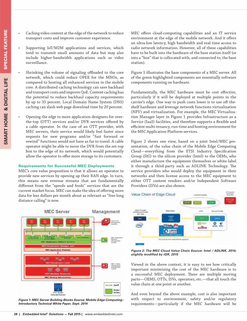
28 | Embedded Intel® Solutions — Fall 2015 | www.embeddedintel.com
SP
EC
IAL
FEA
TU
RE
SM
AR
T H
OM
E &
DIG
ITA
L LI
FE
Caching video content at the edge of the network to reduce
transport costs and improve customer experience.
Supporting IoT/M2M applications and services, which
tend to transmit small amounts of data but may also
include higher-bandwidth applications such as video
surveillance.
Shrinking the volume of signaling offloaded to the core
network, which could reduce OPEX for the MNOs, as
compared to hosting all enhanced services in the mobile
core. A distributed caching technology can save backhaul
and transport costs and improve QoE. Content caching has
the potential to reduce backhaul capacity requirements
by up to 35 percent. Local Domain Name System (DNS)
caching can slash web page download time by 20 percent.
Opening the edge to more application designers for over-
the-top (OTT) services and/or DVR services offered by
a cable operator. In the case of an OTT provider, with
MEC servers, their service would likely feel faster since
requests for new programs and/or “fast forward or
rewind” functions would not have as far to travel. A cable
operator might be able to move the DVR from the set-top
box to the edge of its network, which would potentially
allow the operator to offer more storage to its customers.
Requirements for Successful MEC DeploymentsMEC’s core value proposition is that it allows an operator to
provide new services by opening up their RAN edge. In turn,
this means new revenue streams that are fundamentally
different from the “speeds and feeds” services that are the
current market focus. MEC can make the idea of offering more
data for less dollars per month about as relevant as “free long
distance calling” is now.
MEC offers cloud-computing capabilities and an IT service
environment at the edge of the mobile network. And it offers
an ultra-low latency, high bandwidth and real-time access to
radio network information. However, all of these capabilities
have to be built into the hardware of the base station itself (or
into a “box” that is collocated with, and connected to, the base
station).
Figure 1 illustrates the base components of a MEC server. All
of the green-highlighted components are essentially software
components running on hardware.
Fundamentally, the MEC hardware must be cost effective,
particularly if it will be deployed at multiple points in the
carrier’s edge. One way to push costs lower is to use off-the-
shelf hardware and leverage network functions virtualization
(NFV) and virtualization. For example, the MEC Virtualiza-
tion Manager layer in Figure 1 provides Infrastructure as a
Service (IaaS) facilities, and therefore supports a flexible and
efficient multi-tenancy, run-time and hosting environment for
the MEC Application Platform services.
Figure 2 shows one view, based on a joint Intel/MEC pre-
sentation, of the value chain of the Mobile Edge Computing
Cloud—everything from the ETSI Industry Specification
Group (SIG) to the silicon provider (Intel) to the OEMs, who
either manufacture the equipment themselves or white-label
it through a third-party such as ADLINK Technology. The
service providers who would deploy the equipment in their
networks and then license access to the MEC equipment to
either OTT content vendors and/or Independent Software
Providers (ISVs) are also shown.
Viewed in the above context, it is easy to see how critically
important minimizing the cost of the MEC hardware is to
a successful MEC deployment. There are multiple moving
parts—OEMS, OTTs, ISVs, operators, etc.—that all touch the
value chain at one point or another.
And even beyond the above example, cost is also important
with respect to environment, safety and/or regulatory
requirements—particularly if the MEC hardware will be Figure 1: MEC Server Building Blocks Source: Mobile-Edge Computing– Introductory Technical White Paper, Sept. 2014
Figure 2: The MEC Cloud Value Chain Source: Intel / ADLINK, 2014; slightly modified by iGR, 2015
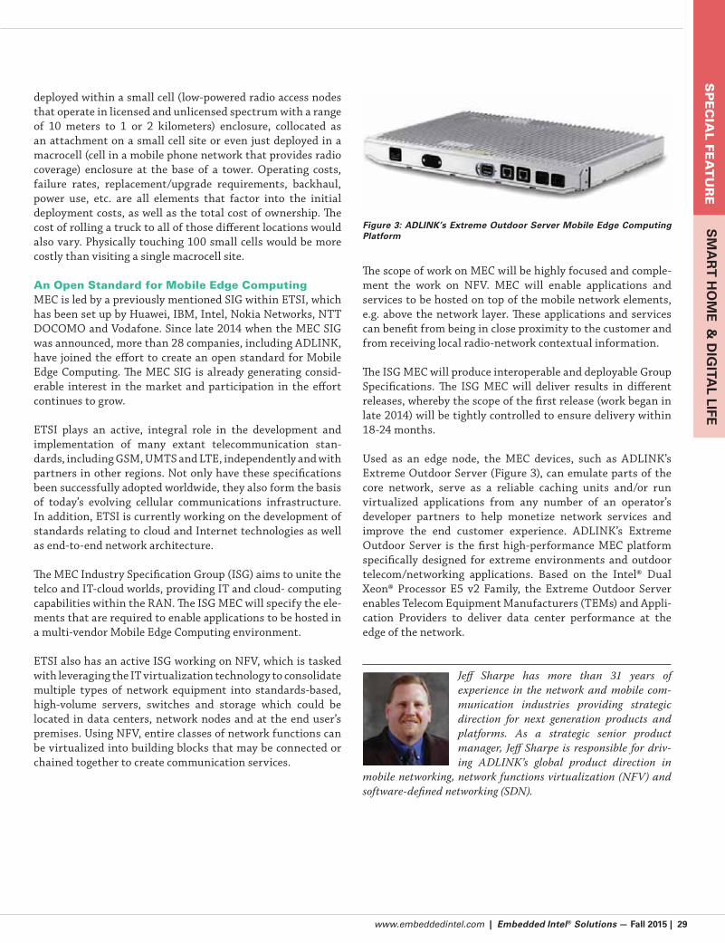
www.embeddedintel.com | Embedded Intel® Solutions — Fall 2015 | 29
SP
EC
IAL F
EA
TU
RE
SM
AR
T H
OM
E &
DIG
ITAL LIFE
deployed within a small cell (low-powered radio access nodes
that operate in licensed and unlicensed spectrum with a range
of 10 meters to 1 or 2 kilometers) enclosure, collocated as
an attachment on a small cell site or even just deployed in a
macrocell (cell in a mobile phone network that provides radio
coverage) enclosure at the base of a tower. Operating costs,
failure rates, replacement/upgrade requirements, backhaul,
power use, etc. are all elements that factor into the initial
deployment costs, as well as the total cost of ownership. The
cost of rolling a truck to all of those different locations would
also vary. Physically touching 100 small cells would be more
costly than visiting a single macrocell site.
An Open Standard for Mobile Edge ComputingMEC is led by a previously mentioned SIG within ETSI, which
has been set up by Huawei, IBM, Intel, Nokia Networks, NTT
DOCOMO and Vodafone. Since late 2014 when the MEC SIG
was announced, more than 28 companies, including ADLINK,
have joined the effort to create an open standard for Mobile
Edge Computing. The MEC SIG is already generating consid-
erable interest in the market and participation in the effort
continues to grow.
ETSI plays an active, integral role in the development and
implementation of many extant telecommunication stan-
dards, including GSM, UMTS and LTE, independently and with
partners in other regions. Not only have these specifications
been successfully adopted worldwide, they also form the basis
of today’s evolving cellular communications infrastructure.
In addition, ETSI is currently working on the development of
standards relating to cloud and Internet technologies as well
as end-to-end network architecture.
The MEC Industry Specification Group (ISG) aims to unite the
telco and IT-cloud worlds, providing IT and cloud- computing
capabilities within the RAN. The ISG MEC will specify the ele-
ments that are required to enable applications to be hosted in
a multi-vendor Mobile Edge Computing environment.
ETSI also has an active ISG working on NFV, which is tasked
with leveraging the IT virtualization technology to consolidate
multiple types of network equipment into standards-based,
high-volume servers, switches and storage which could be
located in data centers, network nodes and at the end user’s
premises. Using NFV, entire classes of network functions can
be virtualized into building blocks that may be connected or
chained together to create communication services.
The scope of work on MEC will be highly focused and comple-
ment the work on NFV. MEC will enable applications and
services to be hosted on top of the mobile network elements,
e.g. above the network layer. These applications and services
can benefit from being in close proximity to the customer and
from receiving local radio-network contextual information.
The ISG MEC will produce interoperable and deployable Group
Specifications. The ISG MEC will deliver results in different
releases, whereby the scope of the first release (work began in
late 2014) will be tightly controlled to ensure delivery within
18-24 months.
Used as an edge node, the MEC devices, such as ADLINK’s
Extreme Outdoor Server (Figure 3), can emulate parts of the
core network, serve as a reliable caching units and/or run
virtualized applications from any number of an operator’s
developer partners to help monetize network services and
improve the end customer experience. ADLINK’s Extreme
Outdoor Server is the first high-performance MEC platform
specifically designed for extreme environments and outdoor
telecom/networking applications. Based on the Intel® Dual
Xeon® Processor E5 v2 Family, the Extreme Outdoor Server
enables Telecom Equipment Manufacturers (TEMs) and Appli-
cation Providers to deliver data center performance at the
edge of the network.
Jeff Sharpe has more than 31 years of
experience in the network and mobile com-
munication industries providing strategic
direction for next generation products and
platforms. As a strategic senior product
manager, Jeff Sharpe is responsible for driv-
ing ADLINK’s global product direction in
mobile networking, network functions virtualization (NFV) and
software-defined networking (SDN).
Figure 3: ADLINK’s Extreme Outdoor Server Mobile Edge Computing Platform

30 | Embedded Intel® Solutions — Fall 2015 | www.embeddedintel.com
SP
EC
IAL
FEA
TU
RE
SM
AR
T H
OM
E &
DIG
ITA
L LI
FE
By Anne Fisher, Managing Editor
An Increasingly Connected IoT and Its Challenges
Q&A with Venkat Mattela, CEO, Redpine SignalsUsing the characteristics of the IoT marketplace to best advantage.
Editor’s note: Venkat Mattela, Redpine Signals CEO, shared
insights with Embedded Intel® Solutions not long after Redpine
announced wireless connectivity modules that feature support for
Intel’s® Moon Island and Bay Trail platforms with Intel Quark™
and Intel® Atom™ processors.
Embedded Intel Solutions: For ultra-low power designs,
how are you meeting the challenge to balance performance,
small circuit area, and low power consumption?
Venkat Mattela: At Redpine, we design
every part of our chipsets and modules from
the ground up. We carry out our own research
and have patented innovations—57 patents
granted so far and more than 200 in the pipe-
line—in all key areas, including low-power
design, high performance wireless receivers,
multi-thread processor architectures, power
aware firmware engineering and systems architecture. Our
approach is to simultaneously work on top-down and bottom-
up design and performance specifications along with actual
implementation and optimization.
Having the whole design team working together enables us
to carry out cross-domain optimization. In wireless systems,
we believe we pioneered the approach of using higher-perfor-
mance implementations to reduce energy consumption. For
example, wireless receivers are required to extract meaningful
data from often heavily impaired signals—such as degraded
signals due to noise, interference, multipath effects and trans-
mitter imperfections. The more complex the processing carried
out on the received signals, the higher would be the chances of
recovering the right data from them. More complex processing
normally implies larger circuit area, and therefore higher cost
and higher power consumption. Here is where we spent over
a decade of extra effort in design and optimization, with the
right innovations, and it makes a difference.
Several individual components of the system influence system-
level performance and power consumption—including the RF
and analog subsystem, receiver signal processing algorithms,
receiver hardware, power management hardware, protocol pro-
cessor design, protocol firmware and chip-level circuit design
and power partitioning. Each component may individually be
designed and optimized for power and performance, but this
will never achieve the levels that are possible with cross-domain
design analysis and system-level optimization.
Embedded Intel Solutions: What’s the best way to keep IoT
momentum going?
Mattela: Devices in the IoT stem from the imagination, which
has no limits. Although technology is available today to support
the conversion of a large number of ideas to products, there is a
clear need to bring in advances.
Communications in the IoT is heterogeneous, and may always
be so. However, there are clear advantages to being able to build
products with Wi-Fi as the connectivity of choice. True ‘Internet
of Things’ implies that every device is on the network, and Wi-Fi
is the best way of getting there—not only in terms of protocol,
but also in performance, ease of use and deployment being sup-
portive of native IP network and energy efficiency.
We have shown that overall energy consumption for many pro-
files of data communication is lower in Wi-Fi than with other
protocols commonly used. The growth of the IoT also depends
on its ability to gather existing and deployed devices into its
fold. Many of these existing devices need help in connecting to
the network, and here is where multiprotocol gateways help. A
wireless connectivity technology developed to support native IP
protocol is the key. Energy harvesting would be used to prolong
battery life, devices would be smaller and even lower cost through
higher levels of integration, such as sensors, computing and con-
nectivity in a single device. Low power is a relative thing. What
was considered low power in devices 10 years ago is considered a
power hog today. Our definition of low power is working without
any battery source, and we are doing some fundamental research
to achieve this milestone to enable IoT in a significant way.

www.embeddedintel.com | Embedded Intel® Solutions — Fall 2015 | 31
SP
EC
IAL F
EA
TU
RE
SM
AR
T H
OM
E &
DIG
ITAL LIFE
The IoT is a very complex framework and involves optimizing
multiple areas to create a sustainable product. It’s not just a
matter of connecting a device to the cloud, or creating one
efficient device. IoT solution creation needs everything from
silicon technology to application development within a cloud
framework. We are using the characteristics of the IoT market
space—an inch-deep, mile-wide market with a long ramp up
cycle—to our advantage to create a differentiated approach to
each component of the IoT solution. We spent over 3000 person
years R&D spanning over a decade to create sustainable differ-
entiations.
Embedded Intel Solutions: In addressing the connectivity pro-
tocol issue as described in your recent news…
“Devices and systems in the Internet of Things
space use different connectivity protocols to sup-
port the underlying application. Our multi-protocol
convergence connectivity solution with support for
dual band Wi-Fi®, dual-mode Bluetooth® 4.0 (Classic
Bluetooth and Bluetooth LE) and ZigBee® enables
seamless connectivity between IoT devices and
the cloud,” said Venkat Mattela, CEO of Redpine
Signals. “By integrating multiple wireless protocols
on to the same chip, Redpine’s solution not only
provides an outstanding customer value for cost but
also removes complex co-existence issues present in
wireless communication.”
Did Redpine also discover practices and ideas that are transfer-
able to working through roadblocks in other areas?
Mattela: We have been carrying out pioneering work on wire-
less coexistence for many years. Coexistence is of course an
obvious issue in unlicensed bands where a multitude of devices
operating on different protocols all operate at the same time. But
it is also a consideration in mitigating the effects of interference
from signals in licensed bands, either adjacent or elsewhere. In
our modules, we have mitigation built in for scenarios where
an IoT device is equipped with other transmitters such as LTE
or GSM. Within the licensed bands, the IoT creates scenarios
where devices in a network operate on different protocols, but
have interdependency and a relationship. In our multiprotocol
modules, we make use of the knowledge of the application and
the system to provide for best-case operation. The methods used
would be useful in addressing issues that have a parallel with
wireless coexistence—for example, devices communicating with
a cloud server. Knowledge of usage patterns would help provide
for the least amount of latencies and wasted ‘wait’ periods.
Implementing the coexistence solution required careful opti-
mization of the computing process internal to our device. Each
protocol has its own context, and handling them seamlessly
required low latency hardware and software operations and the
handling of a very large number of combinations of events and
processes. Ensuring operation within limited memory available
in the device was a major focus.
Embedded Intel Solutions: What’s most misunderstood about
the IoT and industrial deployments?
Mattela: The biggest misunderstanding in IoT is not knowing
the complexity involved in creating a sustainable solution that is
cost effective and easy to deploy.
Misunderstandings can be found at the silicon technology,
devices, network, and cloud and application levels. While a
great deal of work and contributions are coming out in each area,
we see almost everyone taking a short-term approach to solve
a single specific problem. At Redpine we’re addressing this as a
system problem and providing a total solution with significant
innovations at each level.
Industrial installations of automation and control have tradi-
tionally used a wide variety of communication protocols, mostly
wired. When getting them networked into the IoT, there is an
emphasis on wireless interfaces. The difference in communica-
tion behavior between wired systems and wireless systems is
an aspect that is difficult to understand and plan for. Additional
planning and mitigation is often required to create the wireless
network, commonly with a mix of protocols, to offer similar or
better performance compared to the wired connections, along
with the benefits of a unified network the modification brings
about. It takes special effort to understand the planning of the
new wireless network, getting a measure of its performance, and
adapting processes, if required, to operate in the new environ-
ment.
Embedded Intel Solutions: What, if anything, are you seeing
as problems or challenges that are not getting their fair share of
attention in the area of ultra-low-power design?
Mattela: In wireless systems, this is in reality ultra-low energy
design. Therefore, although there are many areas of improve-
ment in power consumption within devices, a potentially bigger
and somewhat neglected contributor to energy inefficiency is the
extent of interference in wireless channels. A lot of time, which
translates to energy, is lost when packets do not reach their
destination—either due to interference or packet collisions—
and when devices have to wait for opportunities to transmit
in the shared channel. This is one challenge in an increasingly
connected IoT. Our company was founded in 2001 on the basis
of providing an ultra-low power Wi-Fi technology, and we have
made significant progress in that regard. We are also creating
IoT devices based on our own wireless chipset providing unprec-
edented usage models when it comes to power dissipation.

32 | Embedded Intel® Solutions — Fall 2015 | www.embeddedintel.com
SP
EC
IAL
FEA
TU
RE
SM
AR
T H
OM
E &
DIG
ITA
L LI
FE
GHz Timing Giving You the Jitters? Three Things You Need to Know
Clock jitter can adversely affect high-speed protocols such as Ethernet, PCI Express
and USB 3.0. You can calm your system down knowing these three simple points.
By Chris A. Ciufo, Editor-in-Chief, Embedded Systems Engineering
Timing is everything, which is why jitter skews every-
thing up. Jitter is the difference between expected and
actual timing edges in a system; the worse it becomes—
the more adversely it affects your system (Figure 1).
Jitter is proportional to lower voltage thresholds, directly
proportional to clock frequency, and a major source of bit
error rate (BER) in high-frequency GHz systems.
In this short primer we’ll:
Show how jitter affects signals at the receiver
Describe the simplest way to reduce source jitter
Show some examples of systems designed with low-jitter
components.
Point #1: High-performance signals require low jitter at receivers.Digital systems require high precision clock sources from
either crystals or crystal oscillators. 40 Gb Ethernet,
for example, requires a clock source with under 0.3ps of
jitter. When there’s jitter in the reference clock, it’s ampli-
fied by clock timers and PLLs in the PHY (Figure 2), since
the phase lock loop responds to the clock edges.
An out-of-phase clock can often skew a GHz signal
beyond an acceptable spec at the receiving end. The
higher the data rate, the more accurate the source timing
source must be. That is: as data rates increase, the jitter
requirements tighten.
Lower jitter means lower BER, and lower BER is better.
Improving jitter lowers BER because at the receiving end,
the Rx circuitry must recover the transmitted clock from
the bit stream by: 1) knowing when to sample the bit stream;
and 2) determining if the data represents a “0” or a “1.” The
encoded bit clock determines when the receiving data is to
be sampled; if the clock is phase-shifted due to jitter, the
receiver may sample the bit stream at the wrong time, which
results in bit errors.
Point #2: Start with a low-jitter clock source at the transmitter.If GHz signals like HDMI (~ 10 Gbits/s) or USB 3.0 (5 Gbits/s)
require low jitter at the transmitter, the best way to reduce
source jitter is to start with an ultra “clean,” low-jitter clock
source.
While jitter has many possible sources at the transmitting end,
the biggest “bang for the buck” can be achieved through the
source clock. A high-quality clock source may widen the jitter
margin of the system (“system” = source, Tx, link, Rx), reducing
the need for extended and excruciatingly complex engineering
effort to reduce second- and third-order jitter sources like
cross-coupled traces or inducted skin effect in PCBs.
Figure 3 shows a crystal oscillator demo board from Pericom
Semiconductor with a 156.25 MHz XO source. The XO popu-
lated on this board is spec’d having a maximum RMS jitter
of 0.2ps—30 percent lower than that required by 40 Gb Eth-
ernet, giving a comfortable Rx margin on an Ethernet link.Figure 1: Jitter as the clock phase shifted from its expected position.
Figure 2: Jitter is amplified by clock timers and PLLs, compounding the problem.

www.embeddedintel.com | Embedded Intel® Solutions — Fall 2015 | 33
SP
EC
IAL F
EA
TU
RE
SM
AR
T H
OM
E &
DIG
ITAL LIFE
Figure 4: Using a phase noise analyzer by Agilent (top) and a LeCroy 6 GHz scope (bottom), the
jitter of the demo board from Figure 3 is shown to be 0.111 ps (shown as 111.949 fs).
Figure 5: A typical low-jitter system starts with an ultra-low-jitter XO. (Courtesy: Pericom Semiconductor.)
How about in actual practice? Using an Agilent phase
noise analyzer and a LeCroy 6 GHz scope, the XO
exhibits a real-world jitter of 0.11 ps, which is well
below that required by 40 Gbits/s Ethernet (Figure 4).
This low-jitter clock source means that other compo-
nents in the system can inject nearly 0.2ps additional
jitter before the link jitter becomes out of spec (and
out of an acceptable BER range). Clearly, starting with
a low-jitter clock source gives a GHz system designer
more breathing room in a design.
Point #3: Know how to use the XO in a system.A typical GHz system is shown in Figure 5. Here, an
ultra-low jitter XO feeds a clock buffer that provides
multiple clocks for a variety of GHz devices, including a
40 GbE PHY, an Ethernet switch and a ternary content
addressable memory (TCAM), part of a layer 3 router.
Pericom’s UX7 series XO is the heart of the low-jitter
system, and is capable of approximately 0.1ps (RMS)
jitter between 12K – 20 MHz as Figure 4 shows.
To avoid using multiple XOs in a system, the
PI6C49S1510 clock buffer can provide up to 10 output
clocks (three are shown in Figure 5), with a very low
additive jitter of 0.03ps—essentially replicating the
XO’s low jitter to all of the outputs. Figure 6 is a screen-
shot of the same bench test as Figure 4 but at an output
downstream of the clock buffer. Note the total RMS
jitter of the XO plus buffer is only 0.15 ps RMS. For
convenience, both the XO and the clock buffer run on
2.5 or 3.3VDC, further simplifying designs.
XO and Buffer All-in-OneAnother way to create low-jitter sys-
tems besides what’s depicted in Figure
5 is to use. Pericom’s FlexOut clock
generator, which combines an XO and
clock buffer into a single package. The
frequencies involved and the need for
ultra clean (low-jitter) clocks, are the rea-
sons the FlexOut PI6CXG05F62a has an
even lower jitter spec than the previously
described XO (~0.1ps [typical]/0.15ps
[max] from 12K – 20 MHz) and supports
up to six outputs in LVPECL and LVDS
configurations.
No external XO is needed (that’s the
whole point!), and neither XO trace
terminations nor XO power filters are
required. This device uses Pericom’s
proprietary quartz timing source with
a special clock IC shrunk into a small
LQFP package that’s smaller than the
two devices it replaces.
Figure 3: The UX704 demo board from Pericom Semiconductor is useful for demonstrating a low-jitter clock source. (Courtesy: Pericom Semiconductor.)
Figure 6: The total jitter of the notional system shown in Figure 5 using Pericom demo boards in the same bench set-up as Figure 4. Total additive jitter is a mere 0.15 ps (RMS).
Regardless of which architecture a designer uses—XO alone, XO plus
clock buffer, or a fancy combo device like the FlexOut—low BER GHz
systems require low jitter. Starting at the transmitter, right at the
clock source.
This article was sponsored by Pericom Semiconductor.

34 | Embedded Intel® Solutions — Fall 2015 | www.embeddedintel.com
SP
EC
IAL
FEA
TU
RE
SM
AR
T H
OM
E &
DIG
ITA
L LI
FE
By Mahbubul Alam, Movimento Group
Why It’s Important to Get on Board the Software-Defined Car
What’s already happened to smartphones and other devices will be disrupting the automotive market.
Pistons and powertrains absorbed all the attention of automo-
tive engineers years ago, but today’s focus will increasingly
be on the software driving the advanced electronics inside
automobiles. Yes, this represents a major disruption, but like
all significant evolutions, it also creates opportunities. Devel-
opments in what’s been called “the software-defined car” are
moving like a Bugatti Veyron Super Sport in several automo-
tive sectors, bringing new Silicon Valley thinking to Detroit.
Nobody would deny that today’s car is a rich hardware platform
bristling with sensors and processors that rely on software.
Graphical displays, touch screens, computer graphics, voice
control—these are becoming the car’s interface, with elec-
tronic sensors and algorithms determining the entire driving
experience to a wide extent. The software-driven features
coming down the road are amazing; not just new auto info-
tainment apps, but completely new features like wholesale
personalization, brand-new advanced driver-assistance
features, extensions for car sharing, regional specific adapta-
tions, car-to-home integration, new vehicle safety options,
remote mobile control, new 4×4 drive modes and more.
Automakers Join OTA SW Update BandwagonThe software-defined car must also be the software-connected
car, with over-the-air (OTA) updates making sure that each
automobile is running the latest, most effective code. OTA
updates began— naturally—with Tesla’s Model S, but the
concept has been speeding forward. At least five automakers
—BMW, Hyundai, Ford, Toyota and Mercedes-Benz—now
offer OTA software updates, with many more likely to join in
over the next 18 months or so.
OTA software upgrades not only affect entertainment systems
but also powertrain and vehicle safety systems. According to
analyst firm Gartner Group, there will be 250 million con-
nected vehicles on the road by 2020 . Within five years, OTA
software upgrades are expected to be commonplace for new
vehicles.
The value of the market for connected car services is forecast
to grow to $148 billion in 2020, reported Pricewaterhouse Coo-
pers (PwC) . Safety-related features are expected to account
for 47 percent, followed by autonomous driving at 35 percent,
with entertainment features accounting for 13 percent. This
networked mobility market represents a tripling from today’s
level and is not only being pushed by demand for connected-
car components, but also by the rise of entirely new digital
business opportunities, stated PwC.
There’s another powerful factoid proving the huge potential
of this no-fuss, no-muss approach to software updates that
has grabbed the attention of the entire auto industry. The first
round in a slew of high-priced acquisitions in the segment
includes Harman International’s $170 million purchase of Red
Bend Software and its $780 million buy of Symphony Teleca.
Thumbs Down on Software Update TravelGiven how consumers use their other electronic devices, they
may soon consider it outrageous that they must either down-
load to a thumb drive or travel to a dealership to have their
vehicle’s software updated. Imagine having to go to a retailer
Figure 1: Software updates will be made over-the-air to the new Software Defined Cars. Photo courtesy Movimento Group

www.embeddedintel.com | Embedded Intel® Solutions — Fall 2015 | 35
SP
EC
IAL F
EA
TU
RE
SM
AR
T H
OM
E &
DIG
ITAL LIFE
to upgrade an application on your smartphone or tablet.
While automotive systems are more complex than consumer
electronics, OTA is clearly the future for electronics-driven
vehicles.
Nevertheless, an automotive-grade solution must be reliable,
secure and safe. It must also handle the numerous interdepen-
dent modules within the car. Customer expectations are much
higher as well. People want “mobile-like” updates with zero
downtime, zero crashes and zero trouble. While customers may
be annoyed when a new software update breaks their phone
for an hour, it’s unacceptable if a broken automotive software
update means that they can’t get to work for the same period.
A Future in Future ProofingMost discussions about vehicle software updates have been
limited to bug fixes, recall avoidance and security patches.
However, with software supplying so many of the car’s capa-
bilities, software updates can give the industry an amazing
degree of flexibility that hasn’t yet been fully realized. One
obvious opportunity is in releasing innovative new software
throughout the vehicle’s entire life. In effect, future-proofing
hardware for the car.
The software-defined car also lets carmakers react in real time
to their customers. OEMs can access anonymous diagnostic
data that lets them see how their cars are being used. Such
access can feed a continual improvement process to develop
new features that customers want. Just like application
updates do today, automotive software updates can fix areas of
continual complaint, add newly requested options and, most
important, create happy, satisfied customers.
The software-defined car must combine deep automotive
expertise, secure over-the-air updates, complete occupant
safety, and flexible diagnostic access to allow process and
product improvements through reliably updatable software.
Fixing Some of Today’s OTA LimitationsWhile OTA is clearly on its way to becoming a standard practice
in the industry, many current vendors haven’t ironed out some
of the limitations in their solutions. One approach to avoiding
concern among automotive OEMs and Tier-1 module manu-
facturers, comes from car software management company
Movimento. The company recently brought to the market a
solution that encompasses the entire software updating needs
of the car as a whole.
Some vendors require brand-specific code to be installed on
every module. But this software often isn’t even available for
older, legacy architectures. OEMs should seek out solutions
enabling all-car updates for the widest list of brands and
models.
Another superior OTA feature worth seeking out is bidirec-
tional data gathering within the car, in which a data agent
gathers vehicle diagnostics, for prognostic and preventative
analytics purposes. This action can provide data to third-party
companies for insurance and other uses. The OTA platform,
such as Movimento’s OTA platform, knows when to use this
data to intelligently know when to safely and proactively apply
the next software update to the car.
Security is an ongoing need in the OTA process to keep autos
safe and minimize the risk of being hacked through monitoring
the vehicle bus and detecting unauthorized messages. Today’s
most advanced approach uses cybersecurity technology to
continually protect the entire vehicle from unauthorized mes-
sages, including security breaches of any kind such as malware.
Mining the Software MindsetThe software-defined car is a huge step forward in a technology
continuum that will eventually bring us production versions of
the driverless car and other major advances rewriting the auto
industry. Consider that a Boeing Dreamliner 787 has 15 mil-
lion lines of code—a tenth of what’s expected in tomorrow’s
driverless cars. Automotive engineers with a software mindset
today will be those best equipped to harness the amazing tech-
nology developments in the near future.
Mahbubul_Alam_headshotMahbubul Alam is CTO, Movi-
mento. Alam joined Movimento as CTO in 2015 and is
responsible for aligning automotive and information tech-
nology with corporate strategy to enable Movimento to lead the
automotive industry’s transition to software-defined vehicles.
A 17-year industry veteran, Alam works with Movimento cus-
tomers to maximize the potential of secure over-the-air (OTA)
updates and enable new connected services for the vehicle.
Previously, Alam led Cisco Systems strategy in IoT and M2M,
where he pioneered and developed this business from the
ground up through vision, strategy, platform and execution.
He also helped initiate the company’s smart connected vehicle
roadmap. Before joining Cisco, Alam held technical leader
positions at Siemens and worked as a technical advisor to the
Dutch government.
Alam holds a master’s degree in Electrical En-
gineering from Delft University of Technology.

36 | Embedded Intel® Solutions — Fall 2015 | www.embeddedintel.com
LAST WORD
By Anne Fisher, Managing Editor
Brick by BrickQ&A with PCI-SIG President and Chairman Al Yanes
and PCI-SIG Board Member Ramin NeshatiPCI Express is a low-cost I/O technology contender that supports a range of
applications, from high performance computing to low-power, mobile devices and anything in between—significant for developers in the embedded and IoT era.
Embedded Intel Solutions: What are some recent activities
of PCI-SIG that have direct bearing on capturing IoT
opportunities?
Ramin Neshati, Board Member, PCI-SIG:
PCI-SIG is interested in ensuring that its
flagship I/O PCI Express (PCIe®) technology
is adopted across the breadth of the industry
and communications technology (ICT)
industry. To increase PCIe support in IoT,
embedded and mobile/low-power usage
models, PCI-SIG is taking steps to educate
its members and the industry at large on the many attractive
features of this technology that have direct relevance to these
emerging and growing market segments.
For instance, PCIe technology is natively supported by all
major operating systems with its robust device discovery and
configuration mechanism; a rich set of power management and
error reporting features; and dynamic, hardware-autonomous
or software-driven link width negotiation procedures to
increase/decrease interconnect lanes as the need arises. For
I/O expansion beyond the chip-to-chip implementations, PCIe
architecture supports a plethora of card, module and cabling
solutions across the compute continuum.
Embedded Intel Solutions: Say you are an engineer thinking
about the ways to make optics cost-effective: What questions
should you ask?
Al Yanes, President, PCI-SIG: While there
is no current work group for optics within
PCI-SIG, if I were to say something [to your
readers] I would say, “Develop cost-effective
optics that the industry could potentially use
in the future.” And, right in line with that,
any questions posed to the subject matter
experts who serve on PCI-SIG technical work groups would
center on two concerns.
One, cost. We are very sensitive to cost. PCIe technologies
are broadly adopted primarily because low cost is one of
our founding principles. Anybody who uses PCI Express
technology in their implementations must be able to do it in
the least expensive manner possible.
The other concern is power. In addition to considering the cost
of implementation and the cost of optics-ready, photonics-
ready components, one must consider how much power is being
consumed. Whether it be an HPC application, PC platform
or low-power mobile device that draws power, computes and
communicates, we want it integrate PCI Express technology.
Nowadays, users are mobile and want their devices to go
with them, which goes hand-in-hand with requirements for
long battery life. For that reason, we insist that PCI Express
technology be a globally recognized low-cost I/O architecture
that can support a breadth of computing devices, from those
requiring high performance computing power to low-power
mobile applications.
Embedded Intel Solutions: Would it be fair to add security to
that list of concerns?
Ramin Neshati, Board Member, PCI-SIG: Yes, but since
security is such an expansive topic let us narrow it down a bit. For
instance, we won’t touch on data encryption or authentication/
access control in this context. Given that a platform can be
envisioned as having a hardware layer, a firmware or virtual
management layer, a layer with the software/OS and then
applications stacked above that, security mostly comes into
play around the middle to top layer—that is where it is relevant
today and that is where most security-related solutions live.

www.embeddedintel.com | Embedded Intel® Solutions — Fall 2015 | 37
LAST WORD
In today’s platform architectures [Security] features don’t
emanate from the hardware layer as much, and that is part
of the problem (the other part being exposed or unprotected
attack vectors). That is one of the reasons why we have growing
threats from viruses, phishing and the like, because there is no
hardware-autonomous way to detect and neutralize malicious
intent and malicious code—whether they originate from
sophisticated hackers or from enterprising “Nigerian royalty.”
The wave of the future may be that security should be embedded
in the hardware. We may be headed in that direction, a move
that the question, “How is PCIe technology going to provide
security features or enable a secure I/O interconnect or link?”
anticipates. Today, the PCI-SIG is not developing “Secure
PCIe” and perhaps there should be a vetting of requirements
and careful analysis of potential solutions. The PCI-SIG is
responsive to the needs of its members and when such a
request picks up steam and the ecosystem pushes for it then
the PCI-SIG will surely respond.
In today’s world, though, security is primarily concerned with
the aforementioned firmware and software layers. However,
having said that, for a structure in which cost is the first brick
and power is the second brick, I can easily see that security will
be the third brick.
Visitwww.embeddedintel.com
Subscribe Today atwww.embeddedintel.com
Free!
S
Gold Sponsors
Spring 2015
Right Sizing
Your Embedded
Application
Smart Fabric, Not Wrist
Bling, To Lead Wearable
Market Growth?
www.embeddedintel.com
Industrial IoT Looks
to SMARC
bscribe Today atb ib T
Gold Sponsors
Summer 2015
Gold Sponsors
www.embeddedintel.com
A Lightbulb Moment for Wearable Technology
IoT Brings Greenfield Opportunity
LAN Bypass for More Robust Networks
Visit
Designing with Intel® Embedded
Processors?
Embedded Intel® Solutions delivers in-depth product, technology and design information to engineers
and embedded developers who design with Intel® Embedded processors
For the range of applications that spans everything from mobile to high performance computing (HPC), the PCI-SIG believes PCI Express can serve as the I/O architecture. Courtesy commons.wikimedia.org

38 | Embedded Intel® Solutions — Fall 2015 | www.embeddedintel.com
Pro
du
ct S
ho
wca
se
Industrial grade wash down Panel PC features a 21.5 inches LCD monitor with 1920 x 1080P full HD display resolution and 5-wire resistive type touch screen. With an onboard 1.83GHz 4-Core Intel® Celeron® processor N2930 and Intel® Atom™ SoC Integrated chipset, the PCH8215 features low power consumption and good performance. Consolidating performance and reliability in one system, the PCH8215 not only delivers high performance with a quad-core processor but its fully IP65/NEMA4X rugged stainless steel chassis and M12 sealed connector and cable also makes this interface suitable for long-term solutions, and especially suitable for environments such as chemical and food processing plants. The PCH8215 provides the best cost performance and high definition HD 1080P graphical performance to support industrial multimedia applications. This new robust Panel PC will include a built in 2GB DDR3 memory module which can easily be upgraded to 8GB if needed. Moreover, it comes standard with one SATA interfaces (1 x 2.5” HDD) for connection of mass storage devices. With multiple I/Os such as 4 x COM, 6 x USB, and dual Gigabit Ethernet make the PCH8215 easier to connect to devices, provide a great solution for a wide range of applications. The PCH8215 is capable of operating in harsh environments with temperature ranging from 32°F to 113°F and relative humidity of 30% to 90%. Its power unit accepts a 12V DC power input and includes an external AC power adapter. Standard VESA mounting holes
are available on the rear for easy mounting to any fixture or wall which enables users to run demanding applications in the field, floor or office environment.
Acnodes Corporation14628 Central Ave.Chino, CA 91710 USAPhone 909-597-7588Fax [email protected]
PCH8215 – Fully IP65 Rated Stainless Steel Panel PC Features 1.83GHz 4-Core Intel® Celeron® Processor N2930
The ADLE3800PC is based on Intel’s first System-on-Chip (SoC) Intel® Atom™ processor E3800 product family, which is built using Intel’s 22nm 3D Tri-gate process. It offers vastly superior compute performance and energy efficiency including Intel’s 7th generation graphics engine for stunning graphics performance. Improved power management capabilities result in standby power measured in milliwatts with days of standby time.
Key FeaturesIntel Atom processor E3800 series SoC, DC/Quad
2x GLAN Ethernet
Applications Areas:
and Defense Applications Including: Unmanned Ground Vehicles, Robotic Subs, Unmanned
Avionics, Unmanned Buoys and Other Surface Vehicles
ADL Embedded Solutions 4411 Morena Blvd Suite 101 San Diego, CA 92117 USA 858-490-0597 858-490-0599 [email protected] www.adl-usa.com
NEW ADLE3800PC – Intel® Atom™ Processor E3800 Series PCIe/104 SBC

www.embeddedintel.com | Embedded Intel® Solutions — Fall 2015 | 39
Pro
du
ct Sh
ow
case
The Artesyn ATCA-7480 blade features dual Intel Xeon E5-2600 v3 processors with up to 28 processing cores per blade. The blade configuration can be optimized for your performance, cooling and power requirements based on a selection of different CPUs from the processor family. Data paths to main memory and I/O are highly optimized and, combined with the scalable memory capacity of up to 512GB, allows for shorter response times of database accesses, accelerated pattern matching and it can help optimize routing decisions in virtualized network environments.
Cost sensitive applications will benefit from the possibility to use up to sixteen memory DIMMs with lower capacity while still achieving attractive memory capacities. The blade can be combined with optional hardware accelerators directly connected to the CPUs. The accelerators are optimized for assisting encryption/decryption algorithms and can greatly enhance throughput of encrypted data in security applications.
The ATCA-7480 features a QuadStar™ interface consisting of four 40G Ethernet channels that connect to the shelf’s backplane. System integrators have the choice of combining channels to different kinds of redundant and non-redundant topologies depending on the applications bandwidth and availability requirements.
With Artesyn’s Silver Lining™ enabling software for SDN/NFV solutions, the ATCA-7480 blade includes support for the Intel® Data Plane Development Kit with accelerated OpenVSwitch,
OpenFlow and OpenStack plug-ins for managing virtualization services on the computing platform. The blade will also support Wind River’s Titanium Cloud.
Artesyn Embedded Technologies2900 S. Diablo Way, Suite 190Tempe, AZ 85282 USAPhone 1 602 438 5720TollFree 1 800 759 [email protected]
The Artesyn SharpStreamer PCIE-7207 high-density video accelerator enables service provider networks to offer video transcoding services quickly and dynamically. As an add-on card, the SharpStreamer PCIE-7207 offers quick and scalable integration with existing and standard server architectures to meet the demands of ISPs and MSOs who want to use existing servers and cloud infrastructure to support new video transcoding services.
With a focus on the high-density and low power demands of video streaming applications such as OTT streaming servers, mobile network optimization, video conferencing, video surveillance and broadcast equipment, Artesyn employs multiple Intel® Core™ i7 processor and GPU accelerated devices in a small and scalable PCI Express card footprint that is easily deployable in off-the-shelf servers.
Compared to dedicated appliances the SharpStreamer solution is more easily deployable, portable, and does not constrain operators to only one type of equipment to monetize OTT streaming content. It also offers network scalability for increased subscribers to pay as you go adding more cards and density from small to large servers as needed. Compared to software-only solutions, the SharpStreamer PCIE-7207 requires far fewer servers and much less operational cost to power video transcoding services.
The SharpStreamer PCIE-7207 is equipped with the Intel® Media Software Development Kit featuring Intel® HD Graphics with fixed-function hardware acceleration, monitoring, and processor subsystem O/S and management tools for easy integration with server host processing environments. SharpStreamer Live and VoD Multiscreen Video Transcoding application software is also available on board, 1U, 2U and dense MaxCore™ configured systems.
ATCA-7480 Packet Processing Blade
SharpStreamer Video Accelerator Card
Artesyn Embedded Technologies2900 S. Diablo Way, Suite 190Tempe, AZ 85282 USAPhone 1 602 438 5720TollFree 1 800 759 [email protected]

40 | Embedded Intel® Solutions — Fall 2015 | www.embeddedintel.com
Pro
du
ct S
ho
wca
se
www.embeddedintel.com | Embedded Intel® Solutions — Fall 2015 | 40
*The IVC300-BT can be woken up by call, G-Sensor, digital input, and alarm
In-Vehicle ComputerIntel® AtomTM Processor E3800 Product Family
Intel® AtomTM processor E3800 supports Windows 7/8.1Integrated with GPS, WLAN, Bluetooth, 3G, and 4G LTEVehicle diagnostic features: RAW CAN, J1939, and OBDIIOptional capture card for 4ch analog camerasSupports 12V/24V power input and is certified by E-Mark and ISO 7637-2Supports event wake up feature for 24/7 remote monitoring*Vibration proof (MIL-STD-810G and 5M3)
Energy-efficient 15W U series platform2 DDR3L SODIMM up to 16GB3 independent displays: 1 VGA, 1 LVDS/eDP, 1 DDI8 PCIe x11 GbE, 4 USB 3.0, 8 USB 2.0, 3 SATA 3.0Supports Intel® Active Management Technology for
remote monitoring
COM Express Compact 6th Gen Intel® CoreTM Processor U Series
SU968IVC300-BT
Smart Embedded Solutions with Low Power
Transportation
S a edded Soo u oo s oo oo e
Headquarters - DFI Inc.10F, No.97, Sec.1, Xintai 5th Rd., Xizhi Dist.New Taipei City 22175, Taiwan, R.O.C.Tel:+886(2)26972986 Http://www.dfi.com
DFI-ITOX, LLC 15 Corporate Place South, Suite 201Piscataway, NJ 08854, U.S.A.Tel:+1(732)390-2815 Http://www.dfi-itox.com
DFI-ITOX, aka ITOX, is a subsidiary company of DFI Inc.
Explore...
➔ Top Stories and News
➔ White Papers
➔ Expert Opinions (Blogs)
➔ Exclusive Videos
➔ Valuable Articles
Sign up for the Embedded Intel® Solutions email newsletter
www.embeddedintel.comEmbedded Intel® Solutions ONLINE
➔ www.embeddedintel.com

Gold Sponsors
Fall 2014
www.embeddedintel.com
Next Generation of Xeon Processors Rolls Out at IDF
Once Earmarked for FPGA
Always Earmarked for FPGA?
From SuperServers to Smart
Beer Kegs
Summer 2014
www.embeddedintel.com
Gold Sponsors
Mobile and IoT Drive Embedded Small Form Factor Evolution
Development Options Evolve with Advances in Intel® Processor Performance-Per-Watt
Advanced Image Stabilization Techniques for Tablet Camera Performance
Meeting the Power Neutrality Challenge in Mobile Handsets
www.embeddedintel.com/china
Delivering in-depth product, technology and design information
www.embeddedintel.com
Gold Sponsors
Winter 2015
www.embeddedintel.com
Securing Embedded Devices in the IoT Era
Automotive Applications
Pursue Higher Performance
Test Equipment Tackles PCIe
Receiver Challenges
A network dedicated to the needs of the global Embedded Intel® community
Gold Sponsors
Spring 2015
Right Sizing Your Embedded Application
Smart Fabric, Not Wrist Bling, To Lead Wearable Market Growth?
www.embeddedintel.com
Industrial IoT Looks to SMARC
Gold Sponsors
Summer 2015
G ld S
www.embeddedintel.com
A Lightbulb Moment for Wearable Technology
IoT Brings Greenfield Opportunity
LAN Bypass for More Robust
Networks
