eindhoven university of technology master … acquaintance to many other ... fortunately r...
TRANSCRIPT

Eindhoven University of Technology
MASTER
Broadband ISDN signalling release 2/3 Stage 2 development
Gerrits, R.W.
Award date:1993
DisclaimerThis document contains a student thesis (bachelor's or master's), as authored by a student at Eindhoven University of Technology. Studenttheses are made available in the TU/e repository upon obtaining the required degree. The grade received is not published on the documentas presented in the repository. The required complexity or quality of research of student theses may vary by program, and the requiredminimum study period may vary in duration.
General rightsCopyright and moral rights for the publications made accessible in the public portal are retained by the authors and/or other copyright ownersand it is a condition of accessing publications that users recognise and abide by the legal requirements associated with these rights.
• Users may download and print one copy of any publication from the public portal for the purpose of private study or research. • You may not further distribute the material or use it for any profit-making activity or commercial gain
Take down policyIf you believe that this document breaches copyright please contact us providing details, and we will remove access to the work immediatelyand investigate your claim.
Download date: 13. May. 2018

t(jj ptt researchIIIF . . • • .
Graduation Report
Broadband ISDN signalling release 2/3Stage 2 development
R.W. Gerrits
Eindhoven University of TechnologyFaculty of Electrical EngineeringDigitallnformation Systems Group
Leidschendam. June 3. 1993
Graduafion professor:Supervisors:
Graduafion period:
Prof. Ir. J. de StigterIr. P.F.C. BlankersIr. H.J.H. BeckersJuly 1. 1992 - June 10. 1993
The Faculty of Electrical Engineering of the Eindhoven University of Technologydoes not accept any responsibility regarding the contents of student graduation reports.

Broadband ISDN signalling release 2/3Stage 2 development
Volume I
R.W. Gerrits

Preface
Somewhere in the Dutch history a guy started to study ElectricalEngineering. I don't mention his name. I know, you don't care.The fellow - let's caB him R - had some kind of goal in his mind, some
thing like: ''Whow, I want to learn EVERYTHING about those dinky electrons. This must begreat!"
By the way, if you say to yourself "Gush, do I feel sleepy.... (same long lasting noise)", then I canbetter warn you in advance: This bunch of paper may be Iess somnolent if you turn over thispage.
After a couple of lectures and a number of years (time flows) R has
made acquaintance to many other 'electrical people' - let's call themü.:..J-~--,:-:,-·-'--'--'c..........-JJ-b:,..:Jstudentsat the Eindhoven University of Technology. He even
$:0f::' learned quite a lot jargon: dinky electrons became nearly infinitesi-(t mal quantum mechanic objects. Help! Electrons do not exist! They'rejust a hotchpotch of quarcks.
Fortunately R discovered that electrons still appear to flow around in his television. So heploughed through every lecture to reach his goal: get that diploma.
But many obstacles arise on the way to become an electrical
engineer. The graphical translation speaks volumes, I suppose.No.. not the one up here but this picture -~
The end comes close, fortuitously. R started his graduation task. A great time out there in
Leidschendam (Mommy, where is the map) happened to be the consequence. How time flies!Now I'm writing this piece of text, thereby finishing my graduation task.Yeah, I know, you found out the mistery R: "He tried to keep it a secret to the end, but I'vebeaten him."
I'm waisting paper. Let's get serious!A lot of people have supported me during my graduation task. I have made acquaintance to
many colleagues during the last twelve months. I'm anxiously awaiting phone calls of people I

ii PREFACE
forgot to mention. Feel free to append your name to the list! Mter you have perceived mywarranty disclaimer, I invite you to read the rest ofthe page.
First I want to thank my family for patiently waiting those many years till the moment arisesthat I graduate. Especially my girl friend, Angela, for supporting me several years. She gave meplenty hearings about stage-2 stuff lately.
I want to thank my friends in Eindhoven and in the Dutch army for helping me to get thingsarranged during my residence near Leidschendam. Before I go deeper into Leidschendam, Imust mention Rian van GaaIen, secretary of the Digital Information Systems Group, for takingcare of the 'final touch.'
We're almost in Leidschendam... we went by car. Okay, I didn't drive. Wim van Berchum hasbrought me home every weekend, and vice versa each Monday (even before sun rise).
Now we enter the building of PTT Research...First I want to thank Patrick Blankers and Harry Beckers for supervising my thoughts andwork from the first day up to now. Also my graduation professor J.de Stigter taking up thechallenge to get me graduated.I'm told that it is very wise to thank your boss. Therefore I thank Jan van Loon for not lettingme minute any meeting (and for not getting angry after reading this, hopefully).
I want to thank all employees of Signalling - oops, Network Control - project group for dealingwith my questions on B-ISDN signalling.In this place 1 want to nominate Pascal Heynen for the personal debugger award (never heard om,because he greatly helped me to get the program Flows what it has become. In this light I haveto thank Guy Reyniers for the many tips.
Finally I thank Murphy for not striking the VAX on the right moment I am printing thisdocument.
Rob GerritsLeidschendam, June 3, 1993
So in a roundabout way I am reaching my goal.

iii
Abstract
In the development of B-ISDN several aspects can be distinguished, like functional descriptionof the signalling system, definition and description of services, data transmission protocols, asspecified by the CCITT three stages characterization methodology. Furthermore B-ISDNsignalling will be introduced in three releases.This report deals with the development of functional network aspects of B-ISDN release 2/3.
First the signalling system of B-ISDN based on separation between call control and connectioncontrol is explored. The benefits and drawbacks of the two level system are identified. Also thestate of the art at the beginning of this graduation task are signed up.
The following step describes several functional models which are the basis of functional networkdescription. After weighing the models against another, the three level model with anintermediate Special Resource Controllevel appears to be too complex as a rudiment for thefunctional description of the B-ISDN network. The proposed AC model seems to have astronghand.
The major part of this report explores scenarios by means of information flow diagrams. Twoparty calls and muItiparty calls pass in review. Both point-to-point and point-to-multipoint withbranching nodes are described utilizing the separated two level model. Multiparty calls havinga non-distributed bridge are described in a complex three level. Also the inner of functionalentities and information flows are studied.
Ensuing the stage 2 characterization methodology, a SDL diagram should be derived. The SDLdiagram developed as part of the task shows a significant difference in complexity between theCC and BC level. It also shows that branching supported by the BC level add just a smallamount of complexity.
Finally the functional specification of a Q.73 demonstrator has been elaborated. This programwill simulate information flow diagrams developed for B-ISDN release 2. The implementation ispartially fulfilled within this graduation task.

Contents
Volume I
v
1 Introduction 1
1.1 Integrated Services Digital Network 11.2 Targets of the Graduation Task 21.3 Outline of the Report 2
2 Broadband ISDN Signalling 32.1 Why New Signalling Systems 32.2 CaB and Connection 32.3 CC and BC 42.4 Separation Between CC and BC 52.5 B-ISDN Introduction in Three Releases 7
2.5.1 New Requirements to Signalling 82.6 Three Stages Methodology for Characterization 82.7 State of the Art 9
2.7.1 Stage 1 B-ISDN 92.7.2 Stage 2 B-ISDN Signalling 112.7.3 Stage 3 B-ISDN Signalling 11
2.8 Conclusions 11
3 Draft Q.73 Functional Models 13
3.1 Goal of Recommendation Q.73 133.2 Basic Functional Model 13
3.2.1 Dynamic Instance of the Model 143.3 Multi-Connection Modelling 153.4 Functional Model for MP Cases 153.5 Multi-Party Modelling 173.6 Functionality of FEs 17
3.6.1 Entities in the BC level 173.6.2 Entities in the CC level 20

vi CONTENTS
3.6.3 Entities in the RC level 213.7 New Developments 223.8 Conclusions 23
4 Information Flow Diagrams 254.1 Introduction 254.2 Point-to-Point Information Flow Diagrams 27
4.2.1 Set Up CaB Only 284.2.2 Add a Connection to an Existing CaB 294.2.3 Release of a CaB With One Connection 314.2.4 Bandwidth Allocation and De-Allocation 324.2.5 Methods of CaB Setup 334.2.6 RoB-back mechanism 35
4.3 Point-to-Multipoint with Branching Nodes 364.3.1 BC Level 374.3.2 CC Level 374.3.3 New Information Flows 374.3.4 Procedures and Mechanisms 38
4.4 Point-to-Multipoint with a Bridge 394.4.1 Activity in the RC Level 394.4.2 BC Level 404.4.3 Procedures 404.4.4 Bridges 41
4.5 Proposed Model with AC Entities 414.6 Individual Information Flow Descriptions 424.7 Conclusions 48
5 SDL Diagram 51
5.1 Introduction 515.2 SDL Diagram of a Two Level B-ISDN Network 515.3 Conclusions 52
5.3.1 General 525.3.2 CaB Setup Procedures 525.3.3 Control of Branching by Relaying BC 535.3.4 Control of a Bridge 53
6 Q.73 Demonstrator 55
6.1 Goal 556.2 User Requirements 55
6.2.1 Language Choice 556.2.2 Environment 556.2.3 User's Profile 566.2.4 Interaction Device 566.2.5 Objects to be Demonstrated 566.2.6 General Screen Lay Out 566.2.7 How to Demonstrate a Scenario 576.2.8 Interaction with the "Presenter" 576.2.9 Interaction with the "Programmer" 57

CONTENTS vii
6.3 Technical Requirements 576.3.1 System Requirements 586.3.2 Programming Language 586.3.3 Type of Scenarios 586.3.4 Configuration 586.3.5 Lay Out of the Program 586.3.6 Setup Parameters 58
6.4 Basic Procedures 596.5 Scenario Description 616.6 Conclusions 61
7 Conclusions and Recommendations 63
References 67
Acronyms 69
Volume 11
AppendicesA DefinitionsBInformation Flow DiagramsC SDL DiagramsD ETSVCCITT Contributions
3
5111207

Introduction
1.1 Integrated Services Digital Network
The public telephone network is excessively digitalized nowadays and the introduction of theIntegrated Services Digital Network (ISDN) is at an advanced stage. An ISDN provides a set ofdigital speech and non-speech services based on a limited set of user-network interfaces (UNI's)and network-node interfaces (NNI's). The ISDN supports both circuit and packet-switchedconnections.A distinction is made between narrowband and broadband ISDN. Narrowband ISDN (N-ISDN)is the network that has been introduced already. It has a restricted capacity and functionality.On the other hand Broadband ISDN (B-ISDN) will be the network with a major capacity andfunctionality. This report will deal with an aspect of the B-ISDN signalling development.Signalling encloses all information exchange to control the network resources required to offerany service.
In the development of B-ISDN several aspects can be distinguished, like functional descriptionof the signalling system, definition and description of services, data transmission protocols, etcetera. Furthermore B-ISDN signalling will be introduced in three releases.The first release (standards to be completed in 1993) uses a monolithic signalling protocol,which means that a one-ta-one relationship exists between "caIl" and "connection." Release twowill be characterized by a separation of the notions "caIl" and "connection," thereby introducingthe possibility of having a call with more than one connection involved. Chapter 2 will digresson the theory about this subject. Also release two will support more supplementary services.The standards for this release is planned to be ready in 1995. The third release, called targetB-ISDN, will support extended multi-media services and broadcast connections (ready in 1997).This report will go inta the functional description of the signalling system of B-ISDN release 2and 3. A functional description delimits entities in a system and describes the way theseentities interact.
International standardization bodies, like ETSI and CCITT, pay much attention to thedevelopment of a functional description of the control system for the future broadband ISDN.The development of this description is still in an early stage. Up ta now the functionaldescription encloses a functional model and a first set of information flow diagrams published inbaseline documents. No released recommendations or standards exists at present. The

2 1 INTRODUCTKJN
functional description is based on separation between eaU control and connection control (seechapter 2), and wiU be the foundation for the future development of signaUing protocols.
1.2 Targets of the Graduation Task
The graduation task includes three targets. The first target is the development of a functionaldescription of the basic eaU for B-ISDN release 2/3. The second target is to design and implement a demonstrator for the signalling system. The requirements of this demonstrator aredescribed below. The final target includes the investigation of the correctness of the results(ETSI and CCITT results and the results of this graduation task) and, if necessary, thesefindings wiU be presented in ETSI and CCITT.
The demonstrator must meet the foUowing requirements:• The demonstrator must show how a control system with separated eaU control and
connection control operates;• The demonstrator must show the benefits of the separation between eaU control and
connection control;• The demonstrator must be easy to work with;• Several scenarios must be demonstrated, e.g. eaU setup, connection setup within an
existing eaU, simultaneous setup of a eaU with one or more connections;• The demonstrator must be easily extendable for new scenarios.
1.3 Outline of the Report
The activities to attain the targets of the graduation task may be grouped in three sets. Thefirst set encloses the (partial) development of the stage 2 functional description. At first newinformation flow diagrams must be developed, e.g. for multi-connection eaUs and multi-partyeaUs. Next SDL1) descriptions of the functional entities in the model must be derived fromthese information flow diagrams. Chapter 4 and 5 wiU go into these subjects. Only switched ondemand services in connection-oriented mode will be discussed in this report.The second set encloses the design and implementation of the demonstrator. This program wiUbe discussed in chapter 6 and - mainly - in [17].The third set includes the testing of scenarios developed by ETSI and CCITT and by the author.Most likely this will result in a number of contributions to ETSI/CCITT.
The foUowing notational conventions will be pursued:Information flows appear in sans-serif condensed typeface.Pascal procedure headers appear in monospaeed typeface.SDL signals appear in Times bold typeface
1) SDL is a standard fonnal language for the specification and description of systems. It has beenstandardized by the CCI'IT. See also chapter 5.

3
~ Broodband ISDN Signalling
2.1 Why New Signalling Systems
The demand for multiparty-, multimedia-, and mobile telecommunication services will increasefast in the near future. The introduction and integration of these new services will have majorconsequences on the telecommunication networks. The B-ISDN network based on ATM offers alot of flexibility: ATM supports a wide range of services. However, this flexibility can onlyoptimaUy be used and these services can only be offered if the signalling system is flexible asweU. The current signalling systems (DSSl, C7) are not able to support these services withoutdue consideration. The control of the services must be revised. This fact requires a newunderstanding of the notions "caU" and "connection" and the introduction of the principle of "theseparation between caU control and connection control" in the telecommunication networks.This chapter will go into several aspects of the development and introduction of B-ISDN. As willbe explained a stepwise method will be used as a structured way to realize B-ISDN. Onlyswitched on-demand services in connection-oriented mode will be discussed.
2.2 CaU and Connect'ion
It is important to define caU and connection to prevent any indistinctness.
Definition of CaU"An association between two or more users or between users and network entities, that isestablished by use of network capabilities to provide a telecommunication service. This association may have zero or multiple information exchange mechanisms established within this caU,for example in connection-oriented or in connectionless modes."
Definition of Connection (1)"An end-to-end association between two or more parties, that provides the transport of userdata."
Definition of Connection (2)"An end-to-end association between two or more parties, that provides the transport of userdata without processing the user data."

4
Definition ofconnection (1)
NeOtwrk- - -."e§][ZJ~----
Point-to-Point Connection
Ne!oD--~e§]0---0-P ' M'" C ' '~0omt-to- u tlpomt onnectlon
NeGtwrk---.e§]0~-----~::,
",,~
MI " P' C' ~u tlpomt-to- omt onnectlon
Neetwrk --~e§]o ~-----,.. :::"~0
Multipoint-to-Multipoint Connection
2 BROADBAND ISDN SIGNALLING
Definition ofconnection (2)
NeOtwrk_ _ - - ."e§][ZJ~------
Point-to-Point Connection
Netwerk_- --~e§][ZJ- -- -->c" ,
'~0P , M I' 'C' Colnt-to- u tlpomt onnectlon
Fig. 2.1 Differences between the two definitions of Connection.
Connections may be uni-directional as weIl as bi-directional. The differences between the twodefinitions of Connection are illustrated in figure 2.1. The first definition is used by the CCITT[9]. The second definition will be used in this report, because it is less confusing:Definition 1 allows the insertion of a bridge in the connection, as will be used in a "conferencecall" to mix and distribute the user data. Definition 2 does treat a bridge as the endpoint of aconnection. 80 all incoming user data (from the bridge point of view) are different connectionsas weIl as the outgoing user data. Figure 2.2 show this distinction. In this figure, the bridge is afunctionality that mixes the incoming user data (e.g. video or audio) and distributes the resultto all involved users.In the lower half of figure 2.2, the bridge is an endpoint for all connections, unlike the upperhalf according to definition 1.
2.3 CC end BC
The formal definition of Call Control (CC) is: "CC controls the call association configurationbetween two or more paries and coordinates zero, one, or more bearer control entities betweenthese parties."The formal definition of (Bearer) Connection Control (BC) is: "BC controls the bearer controlassociation configuration between two or more parties and establishes, modifies, and disconnects the bearer/ATM connection between these parties."The functions CC and BC perform are specifically displayed in table 2.1.

Connections within a "conference caU"for definition 1 of Connection.
2 BROADBAND ISDN SIGNALLING
"@#1~1-88 Connec.~.i?n1"H' :::::1:\//\\·:·:·:·:··
A ,•...,.:..,::..,:...••..,•...:: ..,•...:' ..:•..,•..:•...:•..,•...,: ::'.,•..,•..,•..,,: ·.·.· H.·.·.·.·.·.· ",:.:;;.,:",.,.",.,::..:.:.: :..".:.:.:.0;:; .:.:.'.:.:.:.:.:.:.'.'.:.:.:.'.:.',:.',::.,:.:,:.:,:.:,:.:,•.,.,:.::::::: :::::...::::,::: Connect,'on 1{;j111,'"'' ;"""",,;,," r' ;11WW ""__~;III~
Bridge ~
5
Connections within a "conference caU"for definition 2 of Connection.
Bridge
Fig. 2.2 Distinction between both definitions of Connection in case of a "multipoint.to-multipoint"connection.
The concept of separation between CC and BC in the control system of a telecommunicationnetwork has the consequence that the functionalities of CC and BC are specified separately inthe network. However they may be positioned in the same physical location. The currentsignalling systems have no separation between CC and BC. These systems are called monolithic, because the functions of CC and BC are strongly interweaved. For future signallingsystems the separation between CC and BC will be one of the most important features.
80 the BC level deals with connections only. If one and the same user data stream has to bedelivered at more than one destination, the stream must be split into two or more data streamssomewhere. This is called multicasting.The CC level deals with associations, user requests, and telecommunication services. The CClevel will interchange information with the BC level, the human user, and possibly otherfunctional entities. A functional entity (FE) performs a delimited set of functions and actions bycontrolling resources and interchanging information with other FEs. If two FEs communicate toeach other, a relationship exist between these entities. The formal definitions of FEs and FErelationships can be found in appendix A.
2.4 Separation Between CC and BC
It shall be clear that one call - one association in the CC level - may involve more than oneconnection in the BC level. A potential configuration may be a call between two partiesinvolving a 3.1 kHz audio connection and a 64 kbitJs digital connection, in case of a videophoneconversation. The major difference between a separated signalling system and the monolithicsystem, as modelled in recommendation Q.71 [2], can be found in this feature.

6 2 BROADBAND ISDN SIGNAUlNG
Table 2.1 Functions of the CC and BC levels.
CaU Control (CC)Overall control of the call- setuplrelease of the association(s) between CC entities- selection of next CC node- identification of association(s) between CC entities- maintenance of \he state of the call
Service admission control- telecommunication service screening• user authentication and authorization• service component negotiation- user status checking and monitoring- (re)negotiation of end to end aos- compatibility checking- modification of control 'rights' to CC entities- interworking with existing networks
Communication with BC- give order to setup and release connections- coordination between connections- identification of connections at CC level- collection of charging information
Connection Control (BC)Overall control of the connection- setuplrelease of the association(s) between Be entities- routing (selection of \he next Be node/switching)• maintenance of the state of \he connection- identification of the connection at the Be level
Control network resources- reservation/release network resources- allocation/deallocation of network resources- through-eonnecVdisconnect- (re)negotiation of network resources- interworking with existing networks- modification of control 'nghts' to Be entities
Communication with CC- notification of bearer progress- delivering charging information- notification of change in bearer status (connected, failure, ...)
Another profit is the possibility of coordination between connections by the CC level. Themonolithic signalling system has only one level, which supports only one connection. Speakingin terms of Q.73, a call must be set up for each connection. So no relationship exists betweentwo connections. This fact excludes almost any possibility of shared conditions like commonidentifiers (e.g. in case of videophony, forcing connections to be set up via the same paththrough the network and synchronize them).Except the above mentioned benefit, some other enhancements characterize a separated controlsystem. Considering a three party video conference call, another enhancement will get plain. Inthe CC level one relationship exist, so we're talking about one single call. This relationshipinvolves the three parties and a bridge functionality somewhere in the network. The BC levelwill be organized in a different way: the connections will not exist between all parties, butbetween the bridge and each party. The bridge mixes the incoming speech and video anddistributes the result to all parties. Figure 2.3 shows clearly the difference between the CC leveland the BC level.Having a monolithic signalling system, first a call must be set up between the first party andthe bridge, whereupon the bridge will set up calls to the other parties. So no relation existsbetween two parties, which results in the impossibility to have direct user-to-user signalling.
It is possible to interchange signalling information without setting up a connection. Thisenhancement of signalling system based upon a separation between CC and BC opens thepossibility of setting up a call and a connection sequentially. First the call will be set up. If theother party has a compatible terminal which is idle, the connection will be set up. So nounnecessary bandwidth will be reserved or even allocated if the other party has no freecompatible terminal.Because the CC FEs may be absent in transit exchanges, less processing will occur forend-to-end information. So this information will travel faster through the network, which isanother enhancement of the separated system. Of course the transit exchanges can be moresimple and need less capabilities.Because a different state machine appears for every connection, clear distinction exists betweenall connections. So a clear signalling can be achieved without getting confused about thecondition of a connection.

2 BROADBAND ISDN SIGNALLING
Point-ta-point eall
.!.i!::I.'liIIlli~~'ilil.J.j
7
Fig. 2.3 Difference between CC level and BC level associations: CC level uses end-to-end and BC useslink-by-link association.
Conclusions: The separation between calI control and connection control results in a largeimprovement of the flexibility of the signalling system.As every light has it's shadow, a price must be paid for a separated control system. The systemwill be characterized by a more complex functional description, more complex protocols, and lotsof investments and manpower to standardize and develop this system.
2.5 B-ISDN Introduction in Three Releases
At present ISDN, or more precisely N-ISDN, is about to get operational on large scale. TheN-ISDN gives a subscriber the possibility to make use of a large amount of telecommunicationservices via one single connection. The N-ISDN is an enormous improvement with regard to thecurrent set of service specific networks. Anyhow the end of the developments in the publictelecommunication network wilI be still out of the question. The next step is the developmentand introduction of B-ISDN.The B-ISDN is not a simple extension to the N-ISDN. In fact it will differ substantialIy inalmost any respect; not only the bandwidth and speed, but also the data transfer mode,services, the control system, et cetera. These changes will have a great impact on the publicnetworks. To meet the changed needs, two possible ways can be folIowed: adjust the current

8 2 BROADBAND ISDN SIGNALLING
systems or redevelop and replace the current systems. Adjustment might work in short term,but will not be the solution for the long term. So the CCIT!' decided to standardize a long term,broadband public telecommunication infrastructure, called the target "broadband ISDN," whichis based on data transport via ATM [5]. It must meet all the future needs.
It would be an illusion, that it might be possible to introduce a entire new B-ISDN controlsystem at once. That's why much attention is paid intemationally to the so called "evolutionscenario." It describes how the current network and control systems should migrate to thetarget B-ISDN signalling system. For B-ISDN control systems first a minimum set of serviceswill be identified that will be extended in each following phase. CCIT!' study group XVIII hasdeveloped a table which distinguishes three releases [4]:
• release 1: A short term solution;• release 2: A medium term solution;• release 3: The 'target' solution.
The standards for release 1 signalling are planned to be ready in 1993. Releases 2 and 3 willfollow two respectively four years later on. It's important to realize that release 1 and 2 are onstandards on themselves, because the final aim is target B-ISDN. Compatibility between thesubsequent releases is of major importance for the evolution scenario.Release 1 will still be similar to N-ISDN, but the ATM [5] concept for user data transport willbe the most important feature of this release. New in release 2 are multi-point connections,multiconnection calls and look-ahead procedures. New in release 3 are broadcast connections. Ofcourse each release supports a superset of services according to the prior releases.
2.5.1 New Requirements to 5ignalling
Several factors are the course of a number of new requirements to the B-ISDN signallingsystems. The origin of the most important requirements may be divided in four categories:
• Requirements originating from the telecommunication services, like: distributive services(radio, television), point-to-multipoint configurations (video conferencing), multimediaservices (combinations of speech, video and data), bursty traffic (file transfer);
• Requirements originating from the transport network for user data: the choice for a totalnew transport network introduce new requirements to B-ISDN signalling, because ATMchannels must be controlled in stead of fixed 64 kb/s circuits;
• Requirements originating from the transport network for signalling;• Other conditions, like compatibility requirements for subsequent releases of signalling
protocols.
The need of flexibility in the signalling systems will be met by separating CC and BC and byintroducing a more modular structure.
2.6 Three Stages Methodology for Characterization

2 BROADBAND ISDN SIGNALLING 9
Developing a new signalling system isn't that simpIe, so ad hoc development has a great chanceto terminate early. The characterization of telecommunication services supported by an ISDNand network capabilities of an ISDN can be divided into three main stages of activity [3,10]:
• stage 1: Service aspects;• stage 2: Functional network aspects;• stage 3: Protocol specification aspects.
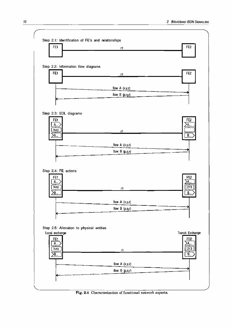
Within each stage a number of steps have been identified. In principle, the application of themethod is sequential, stage 1 giving the service description from the user point of view, stage 2offering an intermediate view of what happens at the user-network interface and inside thenetwork between different exchanges, and stage 3 giving the actual switching and service nodesdescriptions, as weIl as protocols and formats to be adopted.The application of the method for stage 1 results in a description of the service. Stage 2 resultsin one or more implementation independent scenarios, and stage 3 results in a set of protocoland switching recommendations needed to realize the service for each scenario.
Stage 2 has been subdivided into five process steps as can be seen in figure 2.4. These stepsmay be passed through several times, like an iterative process, to complete a stage 2 functionaldescription of a signalling system.
2.7 State of the Art
2.7.1 Stage 1 B-ISDN
The stage 1 descriptions of services from user point of view enclose for each release a number ofservices. The descriptions are taken from a set of draft recommendations coming from CCI'ITstudy group I, like:
• Broadband connection oriented bearer service (draft rec. F.811);• Broadband connectionless data bearer service (draft rec. F.812);• Broadband videotelephony (draft rec. F.722);• Broadband videoconference (draft rec. F.732);• Broadband television distribution service (draft rec. F.821);• Broadband HDTV (draft rec. F.822).
Some examples of release 1 user services are simple point-to-point calls with a single connectionwhich has an 'unrestricted' bandwidth: Continuous Bit Rate (CBR) connection oriented serviceswith end-to-end timing, VariabIe Bit Rate (VBR) connectionless services without end-to-endtiming, and unrestricted bearers with proprietary ATM Adaptation Layer (AAL) [12]. Release 2user services are a superset of the release 1 set, with additions like multi-connection caIl, multipoint caIls, and VBR connection oriented services with end-to-end timing. Release 3 adds multimedia and distributive services.
relationships
10 2 BROADBAND ISDN SIGNALLING
Step 2.1: Identification of FE's and
IFE' 11------.......r1----------I1 m IStep 2.2: Information flow diagrams
FE1 r1 FE2
flow A (x,y,z)
flow B (p,q,r),
Step 2.3: SDL diagrams
FE1 FE2
~ ~r1B... B...
flow A (x,y,z)
flow B (p,q,r)
r-
Step 2.4: FE actions
FE1 .. FE2
~ r1 ~B... B...
flow A (x,y,z)
flow B (p,q,r) --,
I'
Step 2.5: Allocation to physical entitiesLocal exchange Transit Exchange
FE1 FE2
~ r1 ~HB...
flow A (x,y,z)
flow B (p,q,r)
Fig. 2.4 Characterization of functional network aspects.

2 BROADBAND ISDN SIGNALLING
2.7.2 Stage 2 B-ISDN Signalling
11
Because the subject of this report is the stage 2 development of B-ISDN signalling releases 2and 3, the state of the art of this stage will be described more precisely. Involving the basic caB,both releases can be grabbed together because release 3 will be a superset of release 2.
At the start of this graduation task, the stage 2 description enclosed a functional model (step2.1), a number of information flow diagrams (step 2.2), and a part of the overaB B-ISDN stage 2requirements [1,11]. The next chapter will go into Q.73 stage 2 modelling. Yet the functionalmodel is 'frozen' and a possible scenario for aBocation of FEs to Physical Entities (PEs) is alsoidentified (step 2.5). The information flow diagrams that already have been developed are of thescenarios:
••••••••
Point-to-point: simultaneous establishment of a caB with one connection;Point-to-point: simultaneous establishment of a caB with one connection (overlap sending);Point-to-point: sequential establishment of a caB with one connection;Point-to-point: simultaneous release of a caB with one connection;Point-to-point: release of a connection within a caB;Point-to-point: release of a caB without connections;Point-to-point: simultaneous establishment of a caB with multiple connections;Point-to-point: simultaneous release of a caB with multiple connections.
Point-to-multipoint (p-mp), mp-mp, and mp-p information flow diagrams have not beendeveloped yet. See chapter 3 for details.
2.7.3 Stage 3 B-ISDN Signalling
At this time the development of stage 3 is focused on protocol architecture, protocol development, and signalling protocol evolution [1,6,7,11]. The main activities are concentrated on release1. Below some examples are given to show what is going on. Of course this is no complete list ofactivities. The examples are taken from CCITT contributions which were available at thebeginning of this graduation project.Signalling protocol stacks are being developed based on the OSI principles [14]. Some protocolsare in development, like the meta-signalling protocol [8] to set up a signalling virtual channel(VC). Several scenarios of peer-to-peer communication are envisaged of how protocol evolutionfrom release 1 protocol to release 2 protocol could take place by fuBy reusing the release 1protocol in a context sensitive manner controlled by the service. Message functional definitionsand information content (semantics) are studied and specified [13].
2.8 Conclusions
A control system based on separation between CC and BC and the introduction of a moremodular structure results in an improved flexibility which is essential for the second and thirdrelease of the broadband ISDN signalling. The new requirements to the signalling systemoriginate from several sources, especiaBy new telecommunication services.The development ofthe new signalling system for B-ISDN release 2/3 is now focused on thesecond and third stage of the three stages methodology for characterization according to CCITT

12 2 BROADBAND ISDN SIGNALLING
recommendation 1.130. The second stage is divided into five steps that will be passed throughseveral times.The state of the art of stage 2 comprises a functional model and a number of information flowdiagrams for basic point-to-point caBs with point-to-point connections. Basic caB scenariosinvolving other caB and connection types (p-mp, mp-p, mp-mp) must be developed, as weB asscenarios involving other services.

13
~ Oraft Q.73 Functional Models
3.1 Goal of Recommendation Q.73
When finished, eelT!' recommendation Q.73 will enclose a stage 2 description of basic eaUscenarios in the B-I8DN release 2. The draft recommendation is a working document describingthe intermediate results. In this chapter some of the major developments are described to showthe difficulties encountered so faroAt first a functional model has been stated to be used for point-to-point basic eaU scenarios. Anumber of information flow diagram - partly described in this report - are developed for thismodel.The next step is the introduction of multiple parties as weU as multipoint connection types,especiaUy point-to-multipoint unidirectional connections. To support this type of connections, itis studied whether and how the functional model must be extended. Again a set of informationflow diagrams are created based on the modified model. The diagrams form a base for a morestabIe model and for new information flow diagrams involving other connection types.
3.2 Basic Functional Model
Fig. 3.1 Simple basic functional model.
Figure 3.1 show the functional model which has been the base for draft recommendation Q.73.ee and Be functionalities are separated by using two levels. The model shows that relayingnodes not necessarily have a eaU control FE. Also cao be seen that interaction with the useroccurs at the eaU control level only.

14 3 DRAFT Q.73 FUNCT/ONAL MODELS
3.2.1 Dynamic Instance of the Model
The next conventions for reference of directions are defined:• Originating Local Exchange (LEX) is at the side of the originating tenninal and
calling user;• Terminating LEX is at the side of the terminating tenninal and called user;• Incoming side of a node is the side closest to the calling user;• Outgoing side of a node is the side closest 10 the called user;• Forward direction is from the calling user to called user;• Backward direction is from the called user to calling user.
Some FEs are divided into an incoming side and an outgoing side as depicted in figure 3.2.Furthermore the figure shows a possible scenario of allocation of nodes to physical entities. Thisresults in an instance of the functional model as displayed in figure 3.3. For the development ofinfonnation flow diagrams one of both transit exchanges (TEX) is left out, depending on theneed for CC in the relaying node.
Q·LEX
O-LEX: Originating Local Exchange
OCC: Originating Call Control
OSC: Originating Connection Control
IOCC: Incoming Originating CC
OOCC: Outgoing Originating CC
IOSC: Incoming Originating SC
OOSC: Outgoing Originating SC
Fig. 3.2 The FEs are split into an incoming side and an outgoing side; also the node is allocated to aphysical entity: the O-LEX.
O·TE O-LEX TEX T·LEX T·TE
User
............ . .
Fig. 3.3 Enhanced functional model without CC in the relaying node.
User
The functional model depicted in figure 3.3 is used to develop information flow diagrams ofbasic call scenarios involving two parties. This model suffices for these point-to-point scenarios(see also chapter 4). If a call has more than one connection, several BC instances appear: oneinstance for the control of each connection (see also section 2.4 and 3.3). In this case thefunctional model used, is derived from the basic functional model. This model has been adjusted

3 ORAFT Q.73 FUNCT/ONAL MODELS 15
for one scenario in contrast of the basic functional model: the basic functional model forms thepure and most simple - but complete - model.The need of a relationship between an incoming BC and an outgoing BC entity within the samenode is subject of discussion.
The relationships rI2 and rI6 may have the same name, for instance r12, because exactly thesame information will flow through these relationships. This can be argued as follows:If two subscribes are connected to the same local exchange all entities between IOCC and OTCCare absent. 80 only a relationship exists between IOCC and OTCC. The 'left half of thisrelationship is called r12, but the 'right half is called r16. Because by definition no informationwill be altered when travelling from one side to another through a relationship, must obtainr12=r16 in this particular case. Up to now no differences have appeared in other cases, so rI2and rI6 may be identical with an increasing probability.
3.3 Multi-Connection Modelling
The basic functional model has to be modified for scenarios with more than one connection. Toexplain this, the next example focuses on a call involving two connections (e.g. videophone call).For each BC entity two instances occur. Each instance controls exactly one connection, as canbe seen in figure 3.4. Because the model displays only one call, the CC entities appear just once.80 each CC entity may control zero or more BC entities. This conforms the requirement ofhaving a call with more than one connection involved in it.
a-TE a-LEX TEX T-LEX T-TE
User oeeA loeer11
OOCC f------------1 ITee OTCC TeeAr12 r10 r12 r17
User
Fig. 3.4 Instanee of the funetional model for a eaU with two eonneetions. The tubes below the modeldepiet the connections in the user plane.
3.4 Functional Model tor MP Cases
Other basic call scenarios, concerning muItipoint cases, introduce the need of a bridgefunctionality. As has been explained in section 2.2, the existence of a bridge introduces morecomplex situations. It is not clear yet what level the control of the bridge has to be assigned to.The control of the bridge must not be integrated in the CC level to avoid the need for CC FEs inthe relaying nodes. Also it can be assigned to the BC level. In this case the BC entities enclosea number of complex functions. But BC FEs appear many times within a call: one entity foreach connection in each node. 80 this solution may have expensive consequences.

16 3 ORAFT Q.73 FUNCT/ONAL MODELS
The third option is to introduce another level, called Special Resource Control (RC), situatedbetween the CC level and the BC level. This level controls some of the basic call resources:bridges and connections to these bridges. A RC entity enc10ses at least the following functions:
• control of the establishment, release, and modification of a connection by instructing theBC level;
• user data distribution (multicast) for P-MP connections;• user data gathering for MP-P connections;• combination of gathering, and distribution for MP-MP connections.
In this context the notion "gathering" may be explained in two ways: the user data may becollected and directly mixed, or collected and combined by data processing. The implementationconsequences of both explanations differ quite substantial.The first one implies a concatenation of several incoming channels into one output channelwithout processing the user data. Only a number of buffers is required. The latter explanationimplies the need of fast processing capabilities and standardization of the user data format.This type of bridges requires lots of extra hardware.
The three level functional model is still under discussion. As an international workingassumption, it has been agreed that a RC entity will be inserted between every CC and BCentity. So an entire new level has been introduced. In the horizontal direction a relationshipappears between all adjacent RC entities. In the vertical direction the direct relationshipbetween CC and BC stays, but two new relationships are introduced for every CC-RC-BCcluster: one between CC and RC and the other between RC and BC. Figure 3.5 shows thiscomplex model.
a-TE a-LEX TEX T·LEX T·TE
User User
Fig. 3.5 Extended basic functional model having an intermewate level for Special Resource Control.
This model is very hard to deal with. As a working assumption the model has to be simplifiedas far as possible, without introducing extreme restrictions. At first the following restrictionsare assumed:
• The three-level model will be used for MP caBs only;

3 DRAFT Q.73 FUNCT/ONAL MODELS
• If a RC entity is present in a node, all information from CC to BC and vice versa will gothrough the RC entity;
• No RC is required in the TE;• The relations between OORC-IRRC and ORRC-ITRC are equal.
17
The first restriction says that the model presented in figure 3.3 will be used for two-party calls.80 the old model will not be thrown away. The second restriction preserves the RC entities to beby-passed by the CC entities. Now the RC entities will be inforrned about all changes in the BClevel. The third assumption restricts the allocation of bridges to the intemal network. The finalrestriction can be derived by removing the TEX. In this case OORC will be connected directly toITRC.Figure 3.6 shows the three level model that conforms to all mentioned assumptions.
O-TE O-LEX TEX T-LEX T-TE
r10User OCCA
r11IOCC OOCC1------------1 ITCC
r12OTCC TCCA
r12 r17User
r1 IORC OORC IRRCr32 r30 r34
r62
ra
OBCA r21 IOBC OOBC r20 IRBC OABC 120 ITBC omc 126 TBCA
Fig. 3.6 Simplified three level basic model with a possible physical allocation.
3.5 Multi-Party Modelling
The basic functional model has to be modified for scenarios with more than two parties. Figure3.7 show an example of a three party call with one connection involved. As can be seen, thebridge is located in the TEX. Note the different spots at which the call and the connection aresplit. The tube below the model depict the connection in the user plane.
3.6 Functionality of FEs
In this section the functionalities of every FE depicted in figure 3.6 are described in detail. Asubdivision into the three levels is applied to preserve a structured view. The informationdescribed in this section may differ from the standards.
3.6.1 Entities in the Be level

18 3 ORAFT Q.73 FUNCT/ONAL MODELS
a-TE a-LEX TEX T-LEX T-TE
User OCCA IOCC OOCCr11 r12 r10 r12 r17
r53
r1 r2 OORC IRRC ORRC r6 r7 r8rSo r34
OBCA r21 IOBC OOBC r20 IRBC
Fig. 3.7 Instanee of the functional model for a three party caB with one connection. The bridge is locatedin the TEX. The tubes below the model represent the connection in the user plane.
3.6.1.1 Overview
· - . - . - . -
• • • • • • • •
• • • • • • • •• • • • • • • •
- . -
- . .
•
- . . . . -
_.- ._.-
- . -
- . - . . - . -
- . . . . -
- . - . - . -
- . - . - . -
- . - . . - . -
- . - . - . -
- . . . . . . -- . . . . . . -
- . - -
- . . - . - . -
• • • • • • • •
• • • • • • • •
• • • • • • • •
· . -
Setup of the association(s) between BC entities:Release of the association(s) between BC entities:Routing (selection of the next BC node/switching):Maintenance of the state of the connection:Identification of the connection at the BC level:Forward reservation of network resources:Backward reservation of network resources:Forward allocation of network resources:Backward allocation of network resources:Forward through-connect:Backward through-connect:Forward release/deallocation/disconnect:Backward release/deallocation/disconnect:(Re)negotiation of bandwidth:(Re)negotiation of common route connection grouping:(Re)negotiation of QOS of bandwidth:VCINPI negotiation:Interworking with existing networks:Modification of control rights to BC entities:Notification of change in bearer status (progress, connected, .. .):Policing:Delivering charging information:
3.6.1.2 DetailsSetup/release of the association(s) between Be entities. Only outgoing BC entities will set
up a new association between itself and the next BC entity. Both incoming and outgoingBC entities are able to initiate a BEARER RELEASE.

3 ORAFT Q.73 FUNCT/ONAL MODELS 19
Routing (selection of the next BC node/switching). An incoming BC entity needs only tobe associated with the next outgoing BC entity. No external link is involved. So onlyoutgoing BC entities require routing capabilities, excluding the OBCA. The OBCA can beassociated with an IOBC entity of the one O-LEX.Note: from a different point of view can be concluded that incoming BC entities must haverouting capabilities: An incoming BC entity select a route and creates an instance of anoutgoing BC entity to control the selected link.
Maintenance of the state of the connection. Of course each BC entity must be aware of thestate of a connection to be able to control it.
Identification of the connection at the BC level. Also each BC entity must be able toidentify a connection, otherwise it will be impossible to control one single connection.
Forward reservation of network resources. An outgoing entity reserves resources upon anincoming BEARER SETUP request, except for the OBCA. On the O-UNI the IOBC will takecare of the reservation of a forward connection after screening and authorization in theCC level has occurred.
Backward reservation of network resources. Backward reservation functionality is onlyrequired in the OTBC entity for the T-UNI. On the O-UNI and the NNI backwardreservation is applied implicitly by allocation of a connection.
Forward allocation of network resources. All outgoing BC entities, except OBCA, have totake care for allocation of a forward connection. On the O-UNI forward allocation isapplied implicitly by forward through-connection.
Backward allocation of network resources. Backward allocation functionality is onlyrequired in the IOBC entity for the O-UNI. On the NNI and the T-UNI backwardallocation is applied implicitly by backward through-connection.
Forward through-connect. On all external interfaces the incoming BC entities take care forforward through-connection.
Backward through-connect. On all external interfaces the outgoing BC entities take care forbackward through-connection.
(Re)negotiation of bandwidth. All BC entities may be involved in bandwidth negotiation.(Re)negotiation of common route connection grouping. Common route connection
grouping is a feature applicable on network internallinks only. So only BC entitiesinvolved in NNI interfaces require grouping functions.
(Re)negotiation of QOS of bandwidth. All BC entities may be involved in QOS negotiation.VCINPI negotiation. All BC entities, except on the UNI, require VCJNPI negotiation
functions. The OBCA and TBCA are simply instructed to use a suggested identifier. So nonegotiation will be applied with the IOBC and OTBC entities.
Interworking with existing networks. The OBCA and TBCA are assumed to have nointerworking functionality, so functions for interworking at the UNI must be present inthe IOBC and OTBC. Of course all relaying nodes must be able to interwork with otherbroadband networks. The OOBC and ITBC don't require any interworking functionality,because interworking will be taken care of by a gate-way in a relaying node.
Modification of control rights to BC entities. Modification of control rights corresponds tochanging the ownership of a call. Changes to the control rights of entities is only relevanton the UNI, e.g. for control of policing functions.
Notification of change in bearer status (progress, connected, failure, ...). All BC entitieshave to be aware of changes and are thus involved in the notification process.
Policing. Policing must be applied at the UNI by the network and in relaying nodes wheninterworking is utilized with other networks.

20 3 ORAFT 0.73 FUNCT/ONAL MODELS
Delivering charging information. All needed charging inforrnation can be delivered by theIOBC and the OTBC entities. For P-P type connections charging delivery functions arerequired in the IOBC only.
3.6.2 Entities in the CC level
3.6.2.1 Overview
Setup of the association(s) between CC entities:Release of the association(s) between CC entities:Selection of the next CC node:Identification of association(s) between CC entities:Maintenance of the state of the caU:Telecommunication service screening:User authentication and authorization:Service component negotiation:User status checking and monitoring:(Re)negotiation of end-to-end QOS:Compatibility checking:Modification of control rights to CC entities:Interworking with existing networks (see section 3.6.2.2):Give order to set up connections:Give order to release connections:Coordination between resources:Identification of connections at CC level:CoUection of charging information:Give order to set up a bridge/branching node:Give order to release a bridge/branching node:
· - . - . -• • • • • •- - . - . -• • • • • •• • • • • •- • - - •• • -• • - - • •• • - - • •• • - - • •• • - - • •• • - • •- • - - • -· - . - . -• • • • • •• • • • • •• • • • • •- . -
- . -- .
3.6.2.2 DetailsSetup/release of tbe association(s) between CC entities. Only outgoing CC entities will set
up a new association between itself and the next CC entity. Both incoming and outgoingCC entities are able to release a caU.
Selection of tbe next CC node. An incoming CC entity needs only to be associated with thenext outgoing CC entity. No extemal relationship is involved. So only outgoing CCentities require node selection capabilities, excluding the OCCA. The OCCA can beassociated with an IOCC entity of the one O-LEX.
Identification of association(s) between CC entities. Of course each CC entity must beable to identify an association.
Maintenanee of the state of the eaU. Also each CC entity must be aware of the state of thecaU to be able to control it.
Telecommunication service screening. Screening is only needed at the O-UNI and theT-UNI. Screening at the T-UNI is necessary to check ifthe caUed user is also qualifiedto use or subscribed to a service.E.g. consider a two party caU. The B user takes over the ownership of the caU. So if noscreening is applied at the T-UNI, the B user can use a service without subscription.

3 DRAFT Q.73 FUNCT/ONAL MODEL5 21
User authentication and authorization. The authentication and authorization process arerequired at the O-UNI but not at the T-UNI, because this process may be fulfilledwithout setting up any call.
Service component negotiation. Service component negotiation is an end-to-end matter, soall CC entities at the UNIs require functions.
User status checking and monitoring. Of course user status is only relevant at both UNIs,so ooee and ITee entities don't need functions to support user status checking andmonitoring.
(Re)negotiation of end-to-end QOS. Both the network side and the terminal side of theUNIs are involved in end-to-end QOS negotiation.
Compatibility checking. eompatibility checking applied by IOee and OTee entities to findout the terminal type. Also the terminals have to do compatibility checking to find out ifit is connected to the right network type.
Modification of control rights to CC entities. Modification of control rights corresponds tochanging the ownership of a call. Changes to the control rights of entities is only relevanton the UNI.
Interworking with existing networks. The OeeA and TeeA are assumed to have nointerworking functionality, so functions for interworking at the UNI must be present inthe IOee and OTee. The ooee and ITee don't require any interworking functionality,because a LEX is by definition of a different network type if interworking is applied bythe ooee or !Tee. If interworking is required in an relaying node, this node will require(R)ee functionality that is capable to interwork with an existing network. So IRee andORee entities require - if present - interworking functions.
Give order to set up/release connections. All outgoing CC entities may give order to the Beor Re level to set up a connection. Both incoming and outgoing CC entities may giveorder to the Be or Re level to initiate a BEARER RELEASE.
Coordination between resources. All CC entities have supervision of the call and theresources involved. So all entities in the CC level must be able to coordinate resources.
Identification of connections at CC level. Of course all CC entities must be able to identifya connection in order to be able to control it. If a Re entity occurs between a CC and a Beentity, the Re entity will also take care of the identification.
Col1ection of charging information. Only the IOee requires charging information gatheringfunctions assuming the O-user is the owner of the caU.
Give order to set up a bridgelbranching node. If a bridge or a branching node are involvedwith a caB, the initial instantiation of the Re level takes piace in the O-LEX. The ooeehas to give order to the OORe entity to setup a bridge or one or more branching nodes.
Give order to release a bridgelbranching node. The ooee can give order to releasebridges or branching nodes. E.g. a T-user may hang up the phone and thus give order todrop a partylbranch. If two parties are left a bridge may be released and a branchingnodes stops branching on user request. But in a two party caB the owner may prefer tokeep the bridge, even if the third party hangs up.
3.6.3 Entities in the Re level

22 3 DRAFT 0.73 FUNCT/ONAL MoDEL5
3.6.3.1 Overview
Setup of the association(s) between RC entities:Release of the association(s) between RC entities:Selection of the next bridge:Selection of the next branching node:Identification of association(s) between RC entities:Maintenance of the state of a bridge:Identification of a bridge/branching node at the RC level:Bridge hand over:Add party/branch:Drop party/branch:Notification of bridge progress:Modification of control rights to RC entities:
- . - .- . . . .- . -- . - .• • • • • •• • • • • •• • • • • •- . . . . -• • • • • •• • • • • •• • • • • •
3.6.3.2 DetailsSetup/release of the association(s) between RC entities. Only outgoing RC entities at the
NNIs will set up a new association between itself and the next RC entity. The OTRC hasno next entity, so it needs no association setup functions. Both incoming and outgoing RCentities at the NNIs are able to release a association. The IORC and OTRC entities haveno extemal relationships, so they don't need association release functions.
Selection of the next bridge. Only the OORC requires bridge selection functionality,assuming bridges to be non-distributed. If a bridge setup fails, the OORC selects a newone. When a bridge is allocated to the O-LEX or T-LEX no selection functions arerequired.
Selection of the next branching node. Both the OORC and the ORRC entities requirebranching node selection functions, because branching may be distributed in the network.
Identification of association(s) between RC entities. Of course each RC entity must beable to identify an association.
Maintenanee of the state of a bridge. Also each RC entity must be aware of the state of abridge to be able to control it.
Identification of a bridge/branching node at the RC level. Of course all RC entities mustbe able to identify a bridge or branching node.
Bridge hand over. Only internal RC entities require hand over functionality.Add party/branch. All RC entities require addition functions because a new branch may be
added in the bridge or in a branching node wherever that bridge or node appears.Drop partylbranch. Of course all RC entities may drop a party or a branch.Notification of bridge progress. Each RC entity must be aware of the status of the bridge
and are thus involved in the notification process.Modification of control rights to RC entities. Control rights of RC entities cannot be
changes. When the owner of the call changes, hand over will take place in the RC level.
3.7 New Developments

3 DRAFT 0.73 FUNCT/ONAJ.. MODELS 23
The models described in this chapter are not stabilized yet. Especially the three level model is
very generic and needs some time to crystallize or to be dropped. Several new developments can
be observed, based on three statements:
• Some simplifications are agreed because the time limit of December 1993 for stage 2 of BISDN release 2 must be met;
• B-ISDN release 2 and 3 should evolve more directly from B-ISDN release 1;
• Modifications and new concepts as a result of research.
As a simplification it is agreed that MP_pI) and MP-MP connections wiIl not be supported by
release 2. In other words, only bidirectional P-P and unidirectional P-MP type connections will
be modeIled. So the connections meet exactly definition 2 offigure 2.1, which is also a workingassumption for this report.
More direct evolution finds expression in several modeIs, including a monolithic model as usedin Q.71 [2]. Following two examples oftwo-Ievel models illustrate some proposed modifications:
1. The lower level should have the same functionality as Q.71 (consequently called CC level)and the higher level should contain all extra functionality;
2. The lower level used for link-by-link control and the higher level for end-to-end controL
These proposals are partially introduced by developers of stage 3.Some minor modifications are proposed as a result of intended major changes of the stage 3protocol stack. A new concept is the use of object-oriented descriptions of entities (and entirenodes). The model proposed for this concept is depicted in figure 3.8. The AC (Application
Coordination) entities represent objects which contain shared variables, tables and functions.The CC and BC entities interact with the environment and use the AC objects by manipulatingdata and calling any functions. A drawback of the AC model is the extra internal relationshipscompared to the two level functional modeL
3.8 Conclusions
Several functional models are proposed for recommendation Q.73. The two level model asdepicted in figures 3.1 and 3.3 is already very stabIe. For the description of multiparty scenariosthis model is too restricted, so new - more complex - models are proposed. Up to now the verycomplex three level model (CC, RC, and BC levels) is accepted for MP cases. In the near futurethe three level model may be rejected, because it is too complex. The model shown in figure 3.8has a real change to be accepted as the model to describe both point-to-point scenarios as weIlas point-to-multipoint scenarios. The last model settles with questions like which FE on what
level must take care of through-connection, allocation, and reservation.
The functionality of every FE is identified, though the list of functions may be incomplete. Moreimportant is the following: If the RC level will be rejected for some reason, the functions
identified with the RC level must be rearranged in the CC and BC levels.
1) ETSI still supports MP-P connections.

24
User
TE LEX
r14
r34: BC r3t_f
TEX LEX
3 DRAFT Q.73 FUNCT/ONAL MODELS
User
TE............................. . 0............ . .
. AC = Application Coordination........................... . .
Fig. 3.8 Proposed model suited for object-oriented FE description.

25
~ Information Flow Diagrams
4.1 Introduction
An information flow diagram describes whieh information must be interehanged between FEsfor a given scenario. In this section will be explained how to read an information flow diagram.A diagram may be divided into several pages. Figure 4.1 shows an example of a simple page.Two important areas ean be identified:
• Functional entities and relationships• Information flows and aetions
All FEs and relationships together form an instanee of the basic funetional model. FEspositioned on top of eaeh other in the model are plaeed next to eaeh other in the informationflow diagram. This is neeessary to identify the start and endpoint of an information flow. Theleft margin of the first page and the right margin of the last page represent the users. A usermay be a human user or some equipment. If a FE has more than one instance these instaneesare depieted on top of eaeh other, as ean be seen in figure 4.2.The seeond area must be read from top to bottom (the time axis). In this area an informationflow is depieted as an arrow with several labels. The labels deseribe the type of informationtransferred from the souree FE to the destination FE. Optionally some ID numbers are added.These numbers deseribe information elements whieh must be present in the information flow.The ID numbers are described in the baseline text for reeommendation Q.73 [16].
Aetions exeeuted by an FE upon the arrival or departure of an information flow are depieted intwo ways: by using labels and by using ieons. An action label is a code (e.g. a integer number)that describes the action whieh takes plaees in a FE. The action labels are plaeed within thevertieal lines under the FEs.Action ieons deseribe a subset of all possible actions involving the user plane: reservation,allocation, through-eonneetion, and release of bandwidth. The ieons are enumerated in figure4.3. The three ieons deseribing states only are not standardized yet.The ieons happen to be eonfusing, beeause sometimes they rather deseribe a state than anaction. In this report the ieons are used to deseribe a state, whieh is also a tendeney within thestandardization bodies. However appendix B uses icons to deseribe aetions, unless otherwisementioned.

26 4 /NFORMATION FLOW DIAGRAMS
SETUP
"'.
Po/nl-Io-po/nl: eslabllshmenl ofa caH wHhoul connecilons.OtIg/nallng UNI proCedUfII
(Sheel lof3)
R.W.GeM'~
FnOct9.1II12 'U825"l
'"
CALLSETUP
.....
.....
}
Title
Author'5 name,Time 5tamp
Functional Entitie5,RelatJoMhips
....lil"
REPOIU(ptoc-_~.....1010
C.SETuP-
REPOm(*""8l Informatlon FloW5~EJ'OFn 1-~__+---j_---"REP"ê:::-T':!,:'''''.''!L1_+--+__---j_-{ ''IIl.1lIl
1010(,SHUP
1-+>--_+_I-_-":C~=~~S'=~~"''------t_+__+--1I1IClCOl't.. ~:~~~ 10lD
I ..... LegendL:::.......::::::::.:::::..- .....
Fig. 4.1 Example of the page lay out.
.:.;.:.:.:.:.;.;:::;:;:;:;: ,:;:::;:;:;:;::;;= ~:t:tt~r:::r:;
Fig. 4.2 One functional entity may have several instanees.
This chapter will go into a selection of the scenarios that I have developed. At first some pointto-point scenarios are described and some problems and decisions are introduced. Next point-tomultipoint scenarios with branching nodes will be discussed. Finally the most complex point-tomultipoint scenarios with a bridge are described.

4 /NFORMATION FLOW DIAGRAMS 27
Describing an action Describing a state
[] Reserve bandwidth forward Bandwidth reserved forward
~ Reserve bandwidth backward Bandwidth reserved backward
~ Bandwidth allocated forward Bandwidth allocated forward and reserved backward
~ Bandwidth allocated backward Bandwidth allocated backward and reserved forward
B Bandwidth allocated in both directions Bandwidth allocated in bath directions
~ Release bandwidth Bandwidth reserved in both directions
[] Bandwidth allocated forward
~ Bandwidth allocated backward
D Free link
~ Through-connect forward Switch path through-connected forward
~ Through-conneet backward Switch path through-connected backward
8 Through-conneeted in bath directions Switch path through-connected in bath directions
Q9 Disconnect switch path forward
0 Disconnect switch path backward
Q9 Disconnect switch path Switch path disconnected
Fig. 4.3 Overview of all possible ïcons.
Section 4.5 goes into scenarios based on the proposed model with AC entities (see also figure3.8) and section 4.6 deals with the individual information flows.
4.2 Point-to-Point Informa'tion Flow Diagrams
In this section some point-to-point basic eaU scenarios are described, like successful cases ofdifferent types of eaU and connection setup and release.
A simple two party basic eaU can be set up in several ways:
••••
Set up the eaU only (and add connections in a later stage);Set up the eaU with the connection(s) simultaneously;Sequential setup of the eaU and the connection(s);Set up the eaU using overlap sending.
These different types will be discussed in section 4.2.5. First some simple scenarios will bepresented to explain the basic principles and problems.

28 4 fNFORMAnON FLOW DIAGRAMS
CALL SETUP
r ·.1 r11 l_i~)1 r12
---Ir OCCA r~k--~-l'- r~-~-------=-=-r2-'--1-----{I.;,....",/1.·~····loCCm_.•.?t----=-=-1
SETUP ~1 ----.t-----i
req.
req. indo1010
REPORT (Jr0Cgeding)
C. SETUP
req. indo
J ..-_-'-'RE=-P-=.OR'fT_---1indo
req. indo1010
REPORT (aterling)
REPORT (alerting) req. indo
REPORT8 ..-----+-----i
indo
req. indo1010
C. SETUP
10SETUP
11 ~----+-----iconf.
CALL SETUP
resp. conf.1010
resp. conf.
Fig. 4.4a Set up of a eaU only (O-UNI procedure).
'" Ioocc~ •...---...........,.,...,
~. oose r20
C SETUP
r1011
r16
req. indo CALL SETUP
feq. indo1010
C. SETUP
req. indo
REPORT (alerting)
req. indo
req. indo1010
REPORT (aler1i ng)6
1.. REPORT (a/9rting)
req. inld. C. SETUP
CALL SETUP resp. con!.f----foolIf----j---+------l---j----+---f-----+---j----+----1
C. SETÛP resp. con!.10 ~---+-----j 1010
resp. cort.
Fig. 4.4b Set up of a eaU only (NNI procedure).
4.2.1 Set Up CaU Only
The infonnation flow diagram depicted in figure 4.4 shows a setup scenario of a eaU withoutconnections. In fact the three parts of the diagram must be placed next to each other. AlthoughBe entities are not used in this scenario, they are depicted so the model can be better recognized.In line 1 of figure 4.4a the originating user initiates a eaU by sending a SETUP req. infonnationflow to the OeeA, e.g. by picking up the phone and dialling a number. The terminal equipmentsends a CALL SETUP req. indo to the IOee as areaction to this information flow. The IOee forwardsthe information flow to the ooee by means of a C. SETUP req. indo flow and sends back a REPORT
(proceeding) req. indo flow to infonn the OeeA that it has received and processed the setup flow. TheOeeA reports the user (e.g. by generating a tone in case of a nonnal speech phone call) the newstate. The proceeding flow can also be used to stop a timer which was started after sending thesetup flow. If the timer expires before any response returns from the exchange some action canbe taken, like re-sending the last information flow or informing the user that the exchange has

4 /NFORMATION FLOW DIAGRAMS 29
r16
~r17 ~
~
orBe: r26 ~C SETUP
1req. indo CALL SETUP
1req. indo SETUP
3 1010REPORT (alerting) indo
~
REPORT (a1erting) req. indo5 1010
req. ind
lSETUP
6
CALL SETUP resp.1
C. SETJp resp. con!.8 1010
resp. conf. CALL ALLOCATlON9
req.lnd. SETUP10
con!.
Fig.4.4c Set up of a call only CT-UNI procedure).
failed.When CALL SETUP req. indo is received by the TeeA in figure 4.4c, the called user will be informedabout the incoming call by a CALL indo flow. Also a REPORT (alerting) req. indo information flow is sentback to the originating eeA. The calling user can now be informed that the call has reached thecalled party.After a certain delay the called party reacts by a SETUP resp. flow (e.g. by picking up the phone).The CALL SETUP resp. cont. information flow will be send through the network to the originatinguser to inform that the setup has been completed. Also the OTee sends a CALL ALLOCATION req. Ind.
to the responding terminal. If more terminals have responded to the CALL SETUP req. indo flow, thisflow will allocate the call to the first responding terminal and inform other terminals to stopalerting.ID10 is an information item which identifies the association between two adjacent CC entities.
In case of human users a call without connections doesn't make much sense, because you cannotchatter much without any connections. But if both parties are computers, it is no problem to setup the call first and connections afterward. Depending on the service, alerting the user may bedelayed until at least one connections has been set up.
4.2.2 Add a Connection to on Existing Cal!
If a user wants to add a connection to an existing caU (e.g. add a video connection for videophony) the oeeA receives an ADD BEARER req. information flow, as can be seen in figure BlO-Ba ofappendix B. The oeeA informs the IOee with an ADD BEARER req. indo information flow and sendsa BEARER ENQUIRY req. indo to the originating BeA. The local exchange knows that a bearer will beset up, so the IOee waits for a BEARER ESTABLISHMENT req. indo flow. This flow notifies theestablishment of arelation between the OBeA and IOBe entities.Thus the CC level instructs the Be level to set up a connection. In the CC level information hasbeen sent from oeeA to Ioee about changes to take place. The IOee will inform the ooee inan equivalent way. In the Be level the bearer will be set up on CC request. The CC will beinformed about any progress, in order to control the Be level.

30 4 fNFORMATION FLow DIAGRAMS
ID2 is an information item which identifies the association between two adjacent BC entities. ID1
identifies the "bearer" between two adjacent BC entities [16, pp 41-44].
In figure BlO-6 of appendix B action icons are depicted near most BC FEs. Following strategiesare used for establishment or release of connections:
• Connections in the forward direction are reserved upon forward travelling BEARER SETUP
req. indo and BEARER ENe. req. indo flows. Both allocation and through-connection of forwarddirected connections takes place upon backward travelling BEARER SETUP resp. cont. andBEARER EST. resp. conf. information flows. This ensures that no user data can be sent untilthe entire bearer has been set up and charging has started;
• Connections in the backward direction are allocated and through-connected as soon aspossible (upon BEARER SETUP req. indo and BEARER ENe. req. ind.), excluding the terminating UNI.80 the T-user is unable to send user data until the bearer is explicitly allocated by aBEARER ALLOCATION req. indo information flow.
• By definition the BCA FEs do not reserve, allocate, or through-connect any connection.They simply accept or reject a setup request.
sheet Cline) actions
)
...
......
...
................>
................>
)
................>
................>
................>
................>
)
.................>
................>
.................>
~.................>
.................>
.................>
.................>(
81 O-Ga (1G)
810-Gb(18)
81 O-Gb (17)
810-Gb (19)
~[]
~[]~[]171 r\:I < .~ IL.J > > > >
.. / ..•.........•·WtHtilJgtori'ilspilh$iffflitrfCallëduseit.>····· ..< .••••~ .••~.
810-Ge (1G) 'a~
€)EJ€)EJ€)
810-Gb(5)
81 O-Ge (3)
810-Gb (1G)
810-Gb (3)
810-Ga (4)
---~) bandwidth allocated (forward directed)
( bandwidth allocated (backward directed).................> bandwidth reserved (forward directed)
~ switch path through-connected
Fig. 4.5 Add aconnection to an existing eaU: activity in the user plane.

4 /NFORMA TlON FLOW DIAGRAMS 31
In the light of the above mentioned strategies, the action icons in figure B10-6 are easier tounderstand. Sometimes it is not obvious which external link is involved. Figure 4.5 illustratesthe activity in the user plane for this scenario.Observe the action icons depicted in figure B10-6b on lines 17 and 19. These actions do notapply on the expected extemal relationships between ORBC - ITBC and OOBC - IRBC. Figure4.5 shows that these connections are already allocated.Through-connection of bandwidth implies allocation if no bandwidth has been allocated before.The upper half of figure 4.5 illustrates this implied allocation of bandwidth twice. Section 4.2.4will go deeper into bandwidth allocation.
4.2.3 Release of a Cal! With One Connection
Figure B10-7 in appendix B shows the information flow diagram of the release of a call withone connection. If the user sends a RELEASE req. flow to the OCCA, a CALL RELEASE req. indo
information flow is sent in the CC level to the IOCC. When finished, the IOCC send a CALL
RELEASE resp. conf. flow to confirm that the call with it's connections has been released. In the BClevel a comparable set of information flows are transferred.
IIIIII 1.::.::111••••••::••1
sheet Cline) actions
0~B1O-7a (4) ~,
Q9~ \-~; ,B10-7b (3)
0~B10-7b (4) ~,. ,
Q9~ \f)B10-7b (5)
0~B10-7b (6) )
B10-7c (3) Q9~
<) bandwidth allocated (forward directed)
bandwidth allocated (backward directed)
switch path through-connected
status is not frozen yet
Fig. 4.6 Release a eaU with one connection involved: aetivity in the user plane.
Figure 4.6 shows the activity in the user plane. The release of bandwidth and disconnectionactions are used in such a way, that some revision will certainly be needed: Bandwidth will bereleased even before the connections have been disconnected. In the forward direction this isallowed, but in the backward direction this strategy will cause troubles: The next adjacent nodewill still transmit user data backward, but the receiving node doesn't know what to do with theuser data transmitted via an undefined connection.Section 4.2.4 will discuss a better procedure. Of course another solution exists: the way B-ISDNrelease 1 and N-ISDN take care of bandwidth deallocation [2].

32 4 INFORMATJON FLOW DIAGRAMS
4.2.4 Bandwidth Allocation and De-Allocation
4.2.4.1 Bearer SetupBoth the procedures for allocating and de-allocating bandwidth, including through-connectionrespectively disconnection, are currently still incomplete.When a connection is set up one Be entity is always the "assigning node" and the next adjacentBe entity is the "non-assigning node." Only the assigning node is able to select the requiredresources on a particular link. In practice the outgoing Be FE may either allocate or justreserve bandwidth on a bearer setup request information flow.
assianina node non-assigning node
,---,-Ii,--nk~()lijiiil,llsllii:iiassignina node
llij:lllllllliijillinon-assigning node
,---,-1J,--'nk~O :t': jij,oolljiiijiijjiili.:.'.:.;.:-:.:::::::::::.:::.
<
reg.
resp.
req.
resp.
)0~req.
)~~reg. )
< resp.
< resp. ~B
8B
The ieans in this figure represent a state
Fig. 4.7a Generic NNI bearer setup procedure with left-to-right assignment priority decrease.
non-assiQninQ node
Illillji~~lelljl.··ij·assigning node
link () 111111~!lllljl!IIII!!1non-assigning node
11111!!!llljll (assigning node
<
reg.
resp.
req.
resp.
)0~reg.
)0~reg. )
< resp.
< resp. 0B8B
The ieans in this figure represent a state
Fig.4.7b Generic NNI bearer setup procedure with left-to-right assignment priority increase.
Another underexposed item in the currently existing information flow diagrams is the fact thatbandwidth has to be allocated on both sides of a link. The information flow diagrams in thebaseline text [16] sometimes use an ambiguous allocation procedure. Bandwidth allocationactions may be explicitly indicated or assumed to occur implicitly by through-connection actions.

4 fNFORMATlON FLOW DIAGRAMS 33
The infonnation flow diagrams in figure 4.7 show two NNI procedures to reserve, allocate andthrough-connect a bidirectional bearer. In figure 4.7a the assignment priority ofthe outgoingBC FEs is higher than the assignment priority of the next adjacent incoming BC entity. So theoutgoing BC FE controls the link. In figure 4.7b the opposite it true. Of course combinations offigure a and b will appear also.
Conclusions: The action that have to be perfonned upon the arrival of an infonnation flowdepends on the Oocally defined) priority of two adjacent nodes. An outgoing BC FE will at leastreserve bandwidth and may allocate bandwidth upon the arrival of a requesting infonnationflow. The actions that a FE has to take to through-connect the switch path depends on thepriority on both sides of the node.The reservation and allocation icons apply on a single link, so both incoming and outgoing BCentities must reserve and/or allocate bandwidth. The through-connection icons apply on theentire node.
4.2.4.2 Bearer ReleaseSection 4.2.3 explained already that the proposed bearer release procedures are incorrect. Theinfonnation flow diagram in figure 4.8 shows a proper NNI bearer release procedure. Backwarddisconnection will happen solely after appropriate bandwidth de-allocation has occurred. Noresponding information flow is sent from ORBC to IRBC, corresponding to the internodeinformation flows in the CC level (see also figure B10-9 of appendix B).
reg. )
link ( ) 1::i!I~lllillllll\!il
reg.)~o
reg.
resp.
®o<
IIIIIIIIII!III (,------,lin----,k~() 11!1111III)®~
reg.
<®o
resp.
The icons in this figure represent a state
Fig. 4.8 Generic NNI bearer release procedure.
At the UNI the procedure will be slightly different, because the BCA FEs will neither deallocate bandwidth nor disconnect a switch path. Figure RG-1 of appendix B shows how releaseof connections takes place according to the above mentioned procedure. The correspondingactivity in the user plane is depicted in figure 4.9.
4.2.5 Methods of Cal! Setup
4.2.5.1 CaU OnlyIn section 4.2.1 the establishment of a call without any connections involved has beenexplained. The sequential setup of a call with one or more connections comes most close to thisuncomplicated scenario.

34 4 /NFORMATION FLOW DIAGRAMS
I!llillll!llsheet Cline) new state
~DRG-1a (4) ,. ,.
@~J ~
RG-1b (3) '" I ~ '" '" ~·········1 ,. ,.
~D ~J
RG-1b (4) '" '" ~,.
@~ ~.J
RG-1b(5)
@DRG-1 b (6 laft) '" I ~·········1 ,.
RG-1b (6 right)~D ~ )
@DRG-1b (7) )
@~ (RG-1c (3) .................>
RG-1c (6) @D---~) bandwidth allocated (forward directed)
( bandwidth allocated (backward directed)
.................> bandwidth reserved (forward directed)
~ switch path through-connected
Fig. 4.9 Release of a eaU with one connection: how activity in the user plane should take plaee.
4.2.5.2 sequential SetupSequential setup uses two steps: first the caU will be set up, immediately foUowed by theestablishment of the connection(s), as can be seen in figures BlO-5 and BlO-l1 of appendix B.In the call controllevel end-to-end negotiation will take place. No bandwidth will be spoiled if,for example, the terminals are incompatible. The connections are set up after the caUedterminal confirmation is received by the calling terminal. The drawback of this way of caUestablishment is the so called "after dial delay." It will take some time before the caU and theconnections are set up.If the caUed party is a mobile user, sequential setup has certain benefits: The CC informationmay travel a long, inefficient route through the network. But the BC information and the userdata can be set up directly to the caUed party's current nodes. See also section 4.2.6.
4.2.5.3 Simultaneous SetupSimultaneous establishment is a faster way to set up a caU with some connections. Theoutgoing CC entities instruct the outgoing BC entities to setup up a bearer by means of aBEARER ENO. req. indo flow and wait for the BC entity's confirmation. Now both the CC FE and theBC FE may send a setup request information flow (CALL SETUP req. indo and BEARER SETUP req. ind). Inthe protocol (stage 3!) these flows may be coUected and sent within a single message.The benefit of simultaneous setup, compared to sequential setup, is the shorter after dial delay.A drawback is the raised probability that bandwidth will be spoiled.So the (human) user will prefer simultaneous setup above sequential setup because of speed,and the network operator will prefer sequential setup because of efficiency. Therefore it may be

4 /NFORMATION FLOW DIAGRAMS 35
necessary to transform one setup method into an other method. Figure BlO-14 of appendix Billustrates a caU setup scenario using simultaneous setup at the O-UNI and sequential setup atthe NNI and T-UNI.
4.2.5.4 Overlap sendingOverlap sending stands for sending the caUed user's address piece by piece and set up the caUwith the connections in portions. The information flow diagram in figure BlO-lO of appendix Bshows a scenario of a caU being setup by overlap sending. 80metimes overlap sending is restrictively caUed digit-by-digit sending, but the address info send in each ADDL. ADDR. req. Ind.
information flow ("additional address info") is not limited to single digits.The user provides some address information (the ADDR.INFO flows in figure BlO-lOa). Theaddress information wiU be transferred through the network by means of ADDL. ADDR. req. indo
information flows up to the node whereto the caU has been set up already. When a node hascoUected enough information to set up the next link a C+B SETUP req. indo is sent from the incomingFE to the outgoing FE of that node. As soon as the terminating terminal has enough information to inform the user about the incoming caU, a REPORT (proceeding) req. indo will be sent back tothe originating user indicating that the address is complete.
Overlap sending is on this moment an underexposed procedure within the standardizationbodies. The currently accepted information flows diagram, which is depicted in figure B10-10, isvery unstable. It is even not clear if an ADDL. ADDR. req. indo flow should be sent to the TBCA andconsequently if the resulting REPORT (proceeding) req. indo flow should be initiated by the OTCC. Thisis the problem: the address is complete if the OTCC can uniquely identify a TCCA. Anyadditional information does belong to the sub-address, which is an supplementary service. Butthe information flow diagram in figure BlO-lO describes a basic caU scenario.
The major drawback of this way of setting up a caU is the need of CC FEs in transit nodes, thusincreasing the complexity and cost of transit exchanges. Also bandwidth wiU be aUocated withthe possibility that an illegal address will be diaUed.It is not possible to wait in the originating LEX until the entire address has been received,because there is (up to now) no way to check whether the last piece of addressing informationhas been received. However, foUowing technique can be used: start a timer at the arrival ofeach ADDL. ADDR. req. indo information flow. The address is assumed to be complete if no subsequent flow arrives before the timer expires. Of course a monstrous after dial delay will beintroduced. Mter the timer expires - let's say 5 to 10 seconds - the entire caU must be set up.The need of CC FEs in transit nodes can be averted by added functionality to the BC entities tolet them deal with the ADDL. ADDR. req. indo information flows.
Two important advantages of overlap sending are the very short after dial delay and theaffiliation to release 1 B-I8DN, N-I8DN, and other networks. The evolution scenarios demandsupport of overlap sending by interworking units at least. The interworking unit may not knowwhether the address is complete. The network wiU still be able to support the caU.
4.2.6 RoU-back mechanism
The roU-back mechanism, based on the "Commitment, Concurrency and Recovery" (CCR)protocol [18], [CCITT rec. X.850, X.851J, is a technique which is speciaUy useful for multipartycaUs and for mobile caUed parties. The mechanism work as foUows: First a request is sent the

36 4 /NFORMATION FLOW DIAGRAMS
called party. The called party responds by accepting or rejecting optional parts c.q. the entirerequest. Finally the calling party decides what configuration will be used and infonns the calledparty about it's decision. After these three steps the requested actions itself may be perfonned,requiring two additional steps in most cases: a requesting and a responding flow.
The information flow diagram in figure B10-15 of appendix B demonstrates a scenario with theroll-back mechanism. First the originating user sends an ADD BEARER req. indo to the terminatingCCA. The terminating CCA responds with an ADD BEARER resp. conf. information flow, whereuponthe originating CCA instructs the BC level to set up the connection. 80 the third step of theroll-back mechanism is embedded in the bearer setup itself.This shortened variant, consisting of two 2-step procedures, is called a look-ahead procedure.The third step ofthe roll-back mechanism is not explicitly described, but the information flow isimplicit dispatched by the BEARER SETUP req. indo flow in the BC level. This is an illegal techniquein stage 2: every implicit infonnation flow is an infonnation flow and must be explicitlydescribed. In stage 3 the flows may be gathered and transmitted in one single message.Sequential setup of a call also uses a look-ahead procedure. But the procedure is only used toset up the call. For the addition or modification of connections within an existing call (thus afterthe sequential setup has been completed) the roll-back mechanism is a serious option.
The difference between the roll-back mechanism and the bearer setup scenario described insection 4.2.2 is the moment that the ADD BEARER resp. conf. information flow is sent. In the normalbearer setup procedure this flow may be combined (stage 3!) with the BEARER SETUP resp. conf. flowand transmitted in one single message. In the look-ahead procedure the ADD BEARER resp. conf.
must essentially be sent before the connection can be set up by the BC level. Hence an extramessage must be transmitted through the network, introducing addition delay.The benefits ofthe roll-back mechanism can be found in mobile users and multiparty calls. Justlike sequential setup, the roll-back mechanism implies that connections can be set up directly tothe current node of a mobile user. In case of multiparty calls a request is sent to all parties.The setup itself will take place after all parties have responded and the calling party hasdecided what configuration will be used.
4.3 Point-to-Multipoint with Branching Nodes
In a branching node user data is distributed without any modification, hence user data willhave to be copied and in the control plane information flows will process differently. In point-tomultipoint scenarios one incoming information flow may cause several nearly identical outgoingflows. In the opposite direction some incoming infonnation flows may be collected resulting inonly one outgoing flow.A branching node can be seen as a very simple bridge or as an extended connection. The latterpoint of view is most interesting, because this implies that a distributive connection comesunder the basic call concept. One aspect has to be emphasized: Branching nodes involve unidirectional distributive connections only. So in one direction user data is distributed and in theopposite direction the bandwidth is zero.Appendix B contains ten infonnation flow diagrams showing scenarios with branching nodesbased on the two level model (figures RGM-1 to RGM-10). Every information flow diagramdescribes three different locations ofthe branching node: within the O-LEX, TEX, and T-LEX.

4 /NFORMATJON FLOW DIAGRAMS
A number of open issues have to be filled in, like where to split the CC and BC level, dodistinctions exist between the CC and BC level, which new infonnation flows are required, areall procedures reusable.
4.3.1 BC level
37
The outgoing BC functional entities get an additional instance in the branching node. So a peerto-peer association exists between BC entities oftwo adjacent nodes, corresponding to the linkby-link significance of associations in the BC level. This way of instantiating BC entities is alsoin alignment with the multi-connection BC instantiation policy for PP scenarios.The consequence of this decision is that within a node a branch occurs in the BC level. Fortunately this comes very close to the user plane behaviour! Another consequence is that onlyintranode relationships will split, hence the procedures on the external relationships will needminimal modifications.
Considering the state-of-the-art switching hardware, the conclusion that branching nodes can behandled by the BC level can be easily drawn. Many switching architectures support user dataduplication, e.g. by copying a portion of user data to several output buffers at once.
4.3.2 CC level
The outgoing CC functional entities get no additional instance in the branching section. CCentities are far more complex than BC entities, so the number of instances should beminimized. Another reason to use a single instance is alignment with the three level model.Section 4.4 will discuss scenarios using the three level model.
Mark the term branching section (first Hne of previous paragraph) in stead of branching node,because branching in the BC level and the user plane may occur in a relaying node while no CCis present in that node. Figures RGM-ld and RGM-le of appendix B show different branchingscenarios for the BC level, without differences in the CC level. In these figures the BC FEs aredepicted but not used. The information flows are even identical. To avoid superfluous figuresand to reduce redundancy in the infonnation flow diagrams unused BC FEs will not bedepicted. Compare figures RGM-l and RGM-2; the figures depict the same scenario.
4.3.3 New Information Flows
Many infonnation flows must be extended to support multiple destination addresses. Someadditional infonnation flows are required to add or remove a party or branch. In the CC levelthe following new infonnation flows appear:
•••
••
ADD PARTY req. indo is used to initiate a CALL SETUP req. indo flow to the new party;ADD PARTY resp. cont. confinns the ADD PARTY req. indo infonnation flow;PARTY SETUP req. indo is used to initiate the bearer establishment part of a sequential setupprocedure;PARTY SETUP resp. cont. confirms the PARTY SETUP req. indo infonnation flow;REMOVE PARTY req. indo initiates a CALL RELEASE req. indo flow to the separating party;
38
•
4 INFORMATION FLOW DIAGRAMS
REMOVE PARTY resp. conf. confirms the REMOVE PARTY req. indo information flow.
These inforrnation flows are transferred on the shared part of the network. Mer the branchingnode the normal CALL SETUP and CALL RELEASE inforrnation flows are used (see figures RGM-7 andRGM-8 of appendix B). Also PARTY SETUP req. indo will result in BEARER ENe. req. indo or BRANCH ENe. req.indo flows (see figure RGM-9).
Following inforrnation flows are added on CC-BC relationships:
• BRANCH ENe. req. indo initiates a BRANCH SETUP req. indo information flow. The latter flow will betransferred to a relaying branching node;
• BRANCH CON. req. indo confirrns the BRANCH ENe. req. indo flow;• BRANCH DEL. req. indo initiates a BRANCH RELEASE req. indo inforrnation flow. The latter flow will
be transferred to a relaying branching node.
These inforrnation flows are used to add or drop a branch in a relaying node without CC.Following inforrnation flows, added in the BC level, are used for the same purpose (see alsofigures RGM-9 and RGM-IO):
• BRANCH SETUP req. indo initiates a BEARER SETUP req. indo inforrnation flow in a relayingbranching node;
• BRANCH SETUP resp. cont. confirms the BRANCH SETUP req. indo flow;• BRANCH RELEASE req. indo initiates a BEARER RELEASE req. indo information flow in a relaying
branching node;• BRANCH RELEASE resp. conf. confirms the BRANCH RELEASE req. indo flow.
4.3.4 Procedures and Mechanisms
Simultaneous setup of a call is no serious option for multiparty scenarios, because called partiesmay reject different optional parts of a call. When sequential setup is applied, the responses canbe collected before the final configuration is set up. Also look-ahead technique is required for auseful bearer addition procedure. Figure RGM-4, 5, 6, 9, and 10 of appendix B illustrate the useof look-ahead procedures.Point-to-multipoint scenarios with branching nodes are not restricted to one single branchingnode per connection. A connection may have several branches.A branch may be appended to uni-directional connections when a party is added in a two partycall, but two dilemmas must be coped with:
• A bi-directional connection cannot branch, because data from a number of parties must bemixed in some way. A bridge is required or the connection must be divided into two unidirectional connections;
• None of the nodes the existing connection is routed along is able to support branching. Inthis case the connection must be re-routed.
Connection modification scenarios are not discussed in this report.
Conclusion: No new mechanisms are required for point-to-multipoint connections, but someexisting establishment procedures cannot be used. Not all connection types may branch. Some

4 fNFORMATION FLOW DIAGRAMS
hardware implementations may not support branching, so not every node can be a branchingnode.
4.4 Point-to-Multipoint with a Bridge
39
A bridge mixes user data and distributes the results. Figure 4.10 shows a block diagram of abridge. The mixer needs to know the meaning of the user data, so the data stream must have acertain restricted format. Hence user data transparency is impossible in a bridge! Theprocessing of user data by mixer may result in either one outgoing data stream for all users, orseveral different data streams.The distributor does exactly the same as a branching node described in section 4.3: distributionof the user data by branching.
user A data
user B data
user N data
mixer
combined user data
distributoruser A data
user B data
user N data
Fig. 4.10 Block diagram of a bridge.
In this report discussion about point-to-multipoint scenarios with bridges will only deal withnon-distributed bridges. Also hand-over of a bridge will not be discussed. The former restrictionimplies that a bridge is always concentrated in one single node. The latter restriction impliesthat a bridge will stay in the same node during the entire call. Of course a call may haveseveral MP connections, each of them having a bridge in a different node.Most features of bridges can be made plausible without dealing with advanced scenarios.Figures RG3-1 to RG3-6 of appendix B show several information flow diagram of PM callscenarios having a bridge. The diagrams use the three level model with an intermediate specialresource control level.
4.4. 1 Activity in the Re Level
The special resource control level gets an instruction of the CC level by means of a RESOURCE
ENe. req. indo information flow to set up a bridge, as can be seen in figure RG3-1 of appendix B.The OORC functional entity selects the location of the bridge. A bridge can be located in anynode, depending on the node's capabilities and the allocation strategy.The bridge sets up all involving bearers. So if the bridge is located in a relaying node, thebearer at the incoming NNI will be set up in reversed order. An exception forms the bearer atthe a-UNI. This bearer will be set up partially before the RESOURCE ENe. req. indo flow, because theB. SETUP req. indo information flow of this bearer causes the RESOURCE ENe. req. indo flow, and after theRESOURCE CON. req. indo flow, because the B. SETUP resp. conf. flow confirms the RESOURCE CON. req. indo
information flow.

40 4 /NFORMATION FLOW DfAGRAMS
When the OOCC FE receives a RESOURCE CON. req. Ind. information flow the bridge and allinvolving connections have been established successfully by the RC level.
Conclusions: The RC level is responsible for the allocation of the bridge and the establishmentof the bridge and all involving connections. If the RC level is present no direct relationshipsexist between the CC and BC FEs. If a call has both 'conference' connections with bridges andpop or poMP connections a configuration as depicted in figure 4.11 may occur. 80 RC entitiesare used for connections with a bridge only.For the RC level a number of new information flows are required to set up and release a bridgeor branch.A bridge is always controlled from the O-LEX, the node the owner of the call is connected to.
~ p.p or distributive PoMP
Fig. 4.11 A eaU configuration involving both bridges and simple pop or uni-direetional poMP eonneetions.
4.4.2 Be Level
In the optimal situation the BC level will not be aware of a bridge. Unfortunately throughconnection in a node must be handling differently if a bridge is involved. An incoming bearer isnot connected to an outgoing bearer, but both bearers are connected to the bridge. Thus boththe incoming and outgoing BC FEs are responsible for through-connection.Considering the AC model (and anticipating a little) thereby assuming that AC FEs areresponsible for through-connection, a major profit of the model can be found for the BC level:The BC entities will only reserve, allocate, and release connections between two adjacent nodes,hence the BC level is not aware of any advanced configurations.
4.4.3 Procedures
To set up a call with point-to-multipoint connections with a bridge, the simultaneous setupprocedure will be unusable for the same reasons as for point-to-multipoint scenarios withbranching nodes.8everal new information flows are required - mainly in the RC level - to support bridges on topof the new information flows for branching nodes. A decision must be made whether connectionsare set up from the origination user to the other parties or all connections are set up from thebridge to all parties. The former procedure requires the connection between the originating userand the bridge to be set up first. I have chosen for the latter solution because all connecti()nsmay be set up simultaneously by this procedure, thus reducing after dial delay.

4 /NFORMATION FLOW DIAGRAMS
4.4.4 Bridges
From the normal point of view a bridge consists of a mixer and a distributor. From a differentstandpoint a bridge can be seen a mixer only, whilst the distributor part is covered by the BClevel and branching nodes. 80 the bridge has a reduced complexity and branching will be dealtwith as normal distributive connections. This point of view excludes the existence of theMP-MP connection type, because the branching bearers have to be uni-directional.The reduced bridge is not studied in this graduation task, but it may be an objective for future(short term) development.
4.5 Proposed Model with AC Entities
41
The basic functional model with AC entities is a likely candidate to replace both the two levelmodel and the three level model with RC entities: It is not as complex as the three level model,and it satisfies the need of additional control facilities for multiparty caBs.Figure AC-! and AC-2 of appendix B show two sequential call setup scenarios using the ACmodel. Figure AC-! illustrates a two party setup with one connection. The internode proceduresin this information flow diagram differ just a hairbreadth from the normal point-to-pointsequential call setup procedures. However, within the nodes the AC entities take over theinformation flows between the CC and BC levels. Also the BC entities embody lessfunctionality. The AC FEs are responsible for through-connection and disconnection of theswitch path. 80 the BC FEs control a bearer between two adjacent nodes on a peer-to-peerbasis. The AC entities mayalso take over some functions of the CC FEs.
Conclusions: The AC FEs are the nucleus of a node, containing shared functions and controllingthrough-connection of incoming and outgoing bearers. AC entities may be used as the interfacing point for intelligent network (IN) purposes.An important purpose of BC and CC FEs is internode information interchange. The BC levelalso controls all connections and the CC level controls all telecommunication services aspects ofthe basic call.
Figure AC-2 of appendix B describes a three party call. This information flow diagram showsthe advantage of relocating the through-connection functions to AC FEs: the BC entities do nothave to be aware of the MP configuration. Only the AC FE in the relaying node acts differently,compared to figure AC-l. Now it controls both the switch path and the bridge. The extrainformation items required to setup and control the bridge are transferred by BC levelinformation flows. BC entities may pass these additional items transparently.
A drawback of the AC model is the extra internal relationships compared to the two levelfunctional model. In stage 3 only the specification of extemal relationships is required to definea protocol. Intemal relationships are merely suited as a guideline for network equipmentmanufacturers: ignoring the intemal node specification may cause a bunch of misery whendealing with standardized expansions in the future.

42 4 /NFORMATION FLOW DIAGRAMS
4.6 Individuallnformation Flow Descrip'tions
In this section a number of individual information flows are described in detail. The informationflows are based on the two level functional model. Table 4.1 shows which information flows aredescribed. Also specified in the table are the relationships the information flows appear within,as weIl as the direction. Note that overlap sending and relaying CC will not be considered.
Table 4.1 Overview of the information flows described in this section. Mer each information flow thedirection and the relationships in which the flow appears are given.
Flows in CC-BC relationshipsBEARER ALLOCATION req. indo fwd r7,r8BEARER CONNECTED req. indo bk r1,r3,r7BEARER DELETE req. indo fwd r1,r2,r3,rG,r7,r8BEARER ENOUIRY req. indo fwd r1,r3,r7BEARER ENOUIRY resp. conf. bk r1,r3,r7BEARER ESTABLISH req. indo fwd r2,rG,r8BEARER ESTABLISH resp. con!. bk r2,rG,r8
Flows in internode relationshipsADD PARTY req. indo fwd r11 ,r1 0ADD PARTY resp. conf. bk r11 ,r1 0BEARER ALLOCATION req. indo fwd r26BEARER RELEASE req. indo fwd r21,r22,r25,r26BEARER RELEASE resp. conf. bk r21,r22,r25,r26BEARER SETUP req. indo fwd r21,r22,r25,r26BEARER SETUP resp. con!. bk r21,r22,r25,r26CALL ALLOCATION req. indo fwd r17CALL RELEASE req. indo fwd r11 ,r1 0,r17CALL RELEASE resp. con!. bk r11 ,r1 0,r17CALL SETUP req. indo fwd r11 ,r1 0,r17CALL SETUP resp. con!. bk r11 ,r1 0,r17C+B SETUP resp. conf. bk r11 ,r1 0RELEASE CONFIRM req. indo fwd r11 ,r1 0,r17RELEASE CONFIRM resp. conf. bk r11 ,r1 0,r17REMOVE PARTY req. indo fwd r11 ,r1 0REMOVE PARTY resp. con!. bk r11,r10REPORT (alerting) req. indo bk r11 ,r1 0,r17REPORT (proceeding) req. indo bk r11
Remaining information flowsBEARER REPORT req. indo both all relationshipsCALL REPORT req. indo both r11
Flows in Intranode relationshipsADD PARTY req. indo fwd r12,r16ADD PARTY resp. con!. bk r12,r16BEARER RELEASE req. indo fwd r12,r23,r16BEARER RELEASE resp. con!. bk r23BEARER SETLIP req. indo fwd r12,r23,r16BEARER SETLIP resp. con!. bk r12,r23,r16CALL RELEASE req. indo fwd r12,r16CALL SETUP req. indo fwd r12,r16CALL SETUP resp. conf. bk r12,r16C+B RELEASE req. indo fwd r12,r16C+B SETUP req. indo fwd r12,r16C+B SETUP resp. conf. bk r12,r16REMOVE PARTY req. indo fwd r12,r16REPORT (alerting) req. indo bk r12,r16
Flows in User-CC relationshipsADD PARTY con!. bk O-userADD PARTY req. fwd O-userALLOCATE con!. bk O-userALLOCATE indo fwd T-userALLOCATE req. fwd O-userALLOCATE resp. bk T-userDEALLOCATE indo fwd T-userDEALLOCATE req. fwd O-userRELEASE indo fwd T-userRELEASE req. fwd O-userREMOVE PARTY req. fwd O-userREPORT indo bk O-userSETUP conf. bk O-userSETUP indo fwd T-userSETUP req. fwd O-userSETUP resp. bk T-user
CALL SETUP req. indo is used to request establishment of a call. This is a confirmed informationflow and CALL SETUP resp. conf. is used to confirm that the call has been established. The requestfor establishment of a call can be originated by the user. This information flow appears withinthe rIO, rll, r12, r16, r17 relationships. The following items of information are or may beconveyed with the CALL SETUP req. indo and CALL SETUP resp. conf. information flows:
Use Item reg. indo resp. conf multi-destination1
protocol info IDI0 mandatory mandatory
bridge capabilities optional note 1bearer info bearer capabilities mandatory
nature of transmission mandatoryATM attributes (in ATM) mandatory mandatory
routing info called number mandatory (n times)1
transit network selection optionaloriginating info called line ID optional

4 INFORMATION FLOW DIAGRAMS
terminating info
access info
connected line ID requestconnected line IDconnected line statusAAL attributes (in ATM)low layer compatibilityhigh layer compatibility
optional
mandatoryoptionaloptional
optionaloptionalmandatoryoptionaloptional
43
NOTEI: bridge functionality depends on the number of caUed users, the nature of transmission, and other user request.
CALL SETUP resp. conf. is used to confirm that the caU has been established. This informationflow appears within the rlO, rll, r12, r16, r17 relationships. See also CALL SETUP req. indo
CALL ALLOCATION req. indo is used to acknowledge that a previously sent CALL SETUP resp. cont.
has been received and accepted. This is an unconfirmed information flow within the r17relationship and is sent from the OTCC functional entity to the TCCA funetional entity.
Useprotocol info
ItemIDIO
reg. indo resp. cont multi-destinationmandatory
CALL REPORT req. indo is an information flow that is used to report status andlor other types ofinformation across the network. The type of information may be indicated, e.g. alerting,suspending, hold, resume, proceeding, etc. This is an unconfirmed information flow that appearswithin the rIO, rll, r12, r16, r17 relationships. The foUowing items of information are or maybe conveyed with the CALL REPORT req. indo information flow:
Useprotocol info
general
ItemIDIOreport typeconnection requestcaUed line categorycaUed line statusreport type specific info
reg. indo resp. cont multi-destinationmandatorymandatoryoptionalmandatorymandatoryoptional
REPORT (proceeding) req. indo is an unconfirmed information flow that is used to indicate thatsufficient address information (or digits) have been received to process a caU attempt. This is aninformation flow within the rll relationship. See CALL REPORT req.lnd. for complete description.
Useprotocol info
ItemIDIOaddress complete
reg. indo resp. cont multi-destinationmandatoryoptional
REPORT (alerting) req. indo is an unconfirmed information flow that is used to indicate thatTCCA functional entity has received and accepted an establishment request and now waits for

44 4 INFORMATION FLOW DIAGRAMS
the user to respond. This is an unconfinned information flow that appears within the rIO, rU,r12, r16, r17 relationships. See CALL REPORT req. indo for complete description.
Useprotocol info
ItemIDIO
reg. indo resp. cont multi-destinationmandatory
BEARER SETUP req. indo is used to request establishment of a connection. This is a confirmedinfonnation flow and BEARER SETUP resp. conf. is used to confirm that the connection has beenestablished. The request for establishment of a connection can be originated by either the useror the network. This infonnation flow appears within the r12, r16, r2l, r22, r23, r25, r26relationships. The following items of infonnation are or may be conveyed with the BEARER SETUP
req. indo and BEARER SETUP resp. conf. information flows:
reg. indo resp. contmandatory mandatorymandatory mandatoryoptional optionalmandatoryl0ptionall
Useprotocol info
bearer info
routing info
terminating infoaccess info
ItemID2IDIOconnection requestIDIbearer capabilitiesnature of transmissiontime slot sequence infoATM attributes (in ATM)called numbertransit network selectionconnected line statusAAL attributes (in ATM)low layer compatibilityhigh layer compatibility
optionalmandatorymandatoryoptional
mandatoryoptionaloptional
mandatory
mandatorymandatoryoptionaloptional
multi-destination
(n times)
NüTEl: not present in the rl relationship.
BEARER SETUP resp. conf. is used to confinn that the connection has been established. Thisinfonnation flow appears within the r12, r16, r2l, r22, r23, r25, r26 relationships. See alsoBEARER SETUP req. indo
BEARER ENQUIRY req. indo is used by a ee functional entity to request a Be functional entityestablishment of a connection. This is a confirmed infonnation flow if establishment of the calland the connection will be simultaneously (in this case BEARER ENQUIRY resp. conf. is used toconfirm that the Be functional entity might be able to establish a connection), else this is anunconfirmed infonnation flow. This infonnation flow appears within the rl, r3, r7 relationships.(See also BEARER CONNECTED req. ind.)
Useprotocol infobearer info
Itemresponse expectedIDI
reg. indo resp. cont multi-destinationoptionalmandatoryl optional1

4 /NFORMATION FLOW DIAGRAMS
NOTEI: not present in the rl relationship.
45
BEARER ENQUIRY resp. conf. is used to confirrn that the BC functional entity has received andaccepted the enquiry request. This information flow appears within the rl, r3, r7 relationships.See also BEARER ENQUIRY req. indo
BEARER ESTABLISH req. indo is used by a BC functional entity indicate a CC functional entitythe establishment of a connection. This is a confirrned information flow and BEARER E5TABLl5H
resp. cont. is used to confirm that the connection has been established. This inforrnation flowappears within the r2, rB, r8 relationships.
Usebearer info
Item!Dl
reg. indo resp. cont multi-destinationmandatory optional
BEARER ESTABLISH resp. conf. is used to confirrn that the connection has been established. Thisinforrnation flow appears within the r2, rB, r8 relationships. See also BEARER E5TABLl5H req. indo
BEARER CONNECTED req. indo is used by a BC functional entity to indicate a CC functionalentity the establishment of a connection. This is an unconfirmed inforrnation flow that appearswithin the rl, r3, r7 relationships.
Usebearer info
ItemIDI
reg. indooptional
resp. cont multi-destination
BEARER ALLOCATION req. indo is used to acknowledge that a previously sent BEARER 5ETUP resp.
cont. has been received and accepted. This is an unconfirmed inforrnation flow within the r7, r8,r2B relationships.
Useprotocol info
Item!D2!DlO
reg. indo resp. cont multi-destinationmandatoryoptional
BEARER REPORT req. indo is an information flow that is used to report status and/or other typesof information across the network. The type of inforrnation may be indicated, e.g. alerting,suspending, hold, resume, etc. This is an unconfirrned inforrnation flow that appears within allrelationships. The following items of inforrnation are or may be conveyed with the BEARER REPORT
req. indo inforrnation flow:
Useprotocol info
ItemID2!Dl!DlOreport type
reg. indo resp. cont multi-destinationmandatoryoptionaloptionalmandatory

46
generalconnection requestcaUed line categorycaUed line statusreport type specific info
optionalmandatorymandatoryoptional
4 /NFORMATION FLOW DIAGRAMS
C+B SETUP req. indo is used to request simultaneously establishment of a caU with a connection.This is a confirmed information flow and C+B SETUP resp. cont. is used to confirm that the caU andthe connection have been established. The request for establishment of a caU can be originatedby the user. This information flow appears within the r12, r16 relationships. (See also CALL
SETUP req. indo and BEARER SETUP req. ind.)
Use Item reg. indo resp. conf multi-destination1
protocol info IDlO mandatory mandatoryconnection request optional optionalbridge capabilities optional note 1
bearer info IDI mandatory optionalbearer capabilities mandatorynature of transmission mandatorytime slot sequence info optionalATM attributes (in ATM) mandatory mandatory
routing info caUed number mandatory (n times)1
transit network selection optionaloriginating info caUed line ID optional
connected line ID request optionalterminating info connected line ID optional
connected line status mandatoryaccess info AAL attributes (in ATM) mandatory mandatory
low layer compatibility optional optionalhigh layer compatibility optional optional
NüTEl: bridge functionality depends on the number of caUed users, the nature of transmission, and other user request.
C+B SETUP resp. conf. is used to confirm that a caU with a connection have been established.This information flow appears within the rIO, rll, r12, r16 relationships. See also C+B SETUP req.indo
CALL RELEASE req. indo is used to request release of a caU. Within the rIO, rll, r17 relationships this is a confirmed information flow and CALL RELEASE resp. conf. is used to confirm that thecaU release request has been received and accepted. Within the r12, r16 relationship this is anunconfirmed information flow.
Useprotocol info
ItemIDI0
reg. indo resp. conf multi-destinationmandatory mandatory

4 fNFORMATlON FLOW DIAGRAMS
CALL RELEASE resp. conf. is used to confirm that a caB release request has been received andaccepted. This information flow appears within the rIO, rll, rl7 relationships. See also CALLRELEASE req. indo
BEARER RELEASE req. indo is used to request release of a connection. Within the r21, r22, r23,r25, r26 relationships this is a confirmed information flow and BEARER RELEASE resp. cont. is usedto confirm that the connection release request has been received and accepted. Within the r12,rl6 relationships this is an unconfirmed information flow.
47
Useprotocol info
ItemID2IDIO
reg. indo resp. cont multi-destinationmandatory mandatorymandatory mandatory
BEARER RELEASE resp. conf. is used to confirm that the connection release request has beenreceived and accepted. This information flow appears within the r21, r22, (r23,) r25, r26relationships. See also BEARER RELEASE req. indo
BEARER DELETE req. indo is used by a CC functional entity to request a BC functional entityrelease of a connection and is used by aBC entity to indicate a CC entity that a connection hasbeen released. This is an unconfirmed information flows that appears within the rl, r2, r3, r6,r7, r8 relationships.
Useprotocol info
Item? IDIO
reg. indo resp. cont multi-destinationmandatory mandatory
RELEASE CONFIRM req. indo is used to request the confirmation of a connection release. This isan confirmed information flow and RELEASE CONFIRM resp. cont is used to confirm the requestedrelease. The information flow appears within the rIO, rll, rl7 relationships.
Useprotocol info
ItemIDIO
reg. indo resp. cont multi-destinationmandatory mandatory
RELEASE CONFIRM resp. conf. is used to confirm the requested release. The information flowappears within the rIO, rll, rl7 relationships. See also RELEASE CONFIRM req. indo
C+B RELEASE req. indo is used to request simultaneously release of a connection and a caB. Thisis an unconfirmed information flow that appears within the r12, rl6 relationships.
Useprotocol info
ItemIDIO
reg. indo resp. conf. multi-destinationmandatory mandatory

48 4 /NFORMATION FLOW DIAGRAMS
ADD PARTY req. indo is used to add a party to an existing eaU. This is an confirmed informationflow and ADD PARTY resp. cont. is used to confirm that the eaU has been extended to the new party.This information flow appears in the r10, rIl, r12, r16 relationships, but only if the existing eaUhas been set up via that same route. Else the ADD PARTY req. Ind. will be changed by the CCfunctional entity to a CALL SETUP req. indo or a C+S SETUP req. indo
Use Item reg. indo resp. conf multi-destinationJ
protocol info ID10 mandatory mandatorybridge capabilities optional note 1
routing info eaUed number mandatory (n times)!
transit network selection optionaloriginating info eaUed line ID optional
eonneeted line ID request optionalterminating info conneeted line ID optional
eonnected line status optionalaccess info AAL attributes (in ATM) mandatory mandatory
low layer compatibility optional optionalhigh layer compatibility optional optional
NÜTE1: bridge funetionality depends on the number of eaUed users, the nature of transmission, and other user request.
ADD PARTY resp. conf. is used to eonfirm that the eaU has been extended to the new party.This information flow appears in the r10, rIl, r12, r16 relationships. See also ADD PARTY req. indo
REMOVE PARTY req. indo is used to remove a party from an existing eaU. This is an eonfirmedinformation flow and REMOVE PARTY resp. conf. is used to eonfirm that the eaU has been shrunk.This information flow appears in the r10, rIl, r12, r16 relationships, but only ifthe existing eaUhas been set up via that same route. Else the REMOVE PARTY req. Ind. will be changed by the CCfunetional entity to a CALL RELEASE req. Ind. or a C+S RELEASE req. indo
Useprotocol info
ItemID10
reg. indo resp. conf multi-destinationmandatory mandatory
REMOVE PARTY resp. conf. is used to confirm that the eaU has been shrunk. This informationflow appears in the r10, rIl relationships. See also REMOVE PARTY req. indo
4.7 Conclusions
The information flow diagrams deseribing point-to-point seenarios are quite stabIe, but otherinformation flow diagrams deseribing MP seenarios are very unstable.The release of bandwidth must be revised in order to ereate an unambiguous user plane state inthe setup and release procedures.

4 fNFORMATION FLOW DIAGRAMS 49
The information flows described in stage 2 may not be mapped on stage 3 messages in advance.So implicit information flows must be explicitly described, although the information flows maybe collected and sent as one single message in stage 3.Several different call setup procedures exist. To support all procedures CC FEs need to berather complex. Simultaneous setup and overlap sending are even unusable for MP configurations.No new mechanisms are required for point-to-multipoint connections, but some existingestablishment procedures cannot be used. Bi-directional connections cannot branch, hence abridge is mandatory in this case. Some hardware implementations may not support branching,so not every node can be a branching node.
The RC level is responsible for the allocation of the bridge and the establishment of a bridgeand all involving connections. If the RC level is present no direct relationships exist betweenthe CC and BC level. In the three level model the BC FEs must be aware of MP configurationsin order to control switch path through-connection and disconnection accurately.The distributing section of a bridge may be seen as a separated branching function. This pointof view excludes the existence of the MP-MP connection type, because the branching bearersmust be uni-directional.
The AC FEs are the core of a node, containing shared functions and controlling throughconnection of incoming and outgoing bearers. AC entities may be used as the interfacing pointfor IN purposes.Within the AC model an important purpose of BC and CC FEs is intemode informationinterchange. The BC level also controls all connections and the CC level controls all telecommunication services aspects of the basic call.
Most information flows for successful two-party basic call scenarios have been studied in detail.A number of mandatory and optional information items have been identified.

51
@ SDL Diagram
5.1 Introduction
An information flow diagram shows the actions and information flows which have to becompleted for one scenario. Mter comparing a lot of information flow diagrams, a overviewarises of the total collection of functions and information flows each FE has to deal with.Of course it is impossible to cover all possible scenarios. Fortunately nobody ever wants todescribe all possible scenarios with information flow diagrams: The SDL diagrams are suited forthese descriptions. SDL is a formal language for the specification and description of systems. Ithas been standardized by CCITT [10].An SDL diagram describes a system embedded into its environment. The environment transfersinformation flows to the system and vice versa. An information flow will also initiate actionsand new information flows in the system. The SDL diagram specifies which actions a system, orparts of the system, will apply.
This report will not go into the syntaxis of SDL. A plain introduction to SDL can be found in abook of F. Belina et al [19].
5.2 SOL Diagram of a Two Level B-ISDN Network
Appendix C contains a SDL diagram of aB-ISDN network, based on the two level model. Thediagram has been derived from a lot of information flow diagrams. First the system issubdivided into nodes, called blocks. Then the nodes are divided into functional entities, calledprocesses. A process may include some services. On the lowest level specify flow diagrams theexact behaviour of each piece of the system.
The SDL description covers point-to-point scenarios, multiple responding terminals, point-tomuItipoint scenarios, and MP calls with some sort of bridge in the O-LEX.In this investigational diagram the control of the bridge is assumed to be handled by the CClevel. For this purpose the CC FEs in the O-LEX are cut into two portions: a typical CC entityand a Mix Control Unit (MCU).
Two side-notes must be added to the SDL diagram:

52
•
•
5 SOL OIAGRAMS
The diagram forms an overview of the network. The syntax may be incorrect in somepoint (simplified notations), and semanticaIly are many parts missing (like formaldescription of signaIs).The diagram is merely based on obsolete information flow diagrams, so a discrepancyexists with the information flow diagrams in appendix B.
The goal of the SDL diagram is investigation of the complexity of entities. Taking into accountthe above mentioned site-notes, this is a workable proposition.
5.3 Conclusions
5.3.1 General
The functional entities in the Be level are far less complex than FEs in the CC level. The CCFEs at the UNI require more functions than CC FEs at the NNI, because the UNI is lessreliable.
Branching nodes are controlled by the incoming side of a node. Observe the IRBe and ORBeprocesses. The incoming Be process selects and instantiates the outgoing Be process. If theIRBe decides that user data has to be transported in several directions, several ORBeprocesses are started (one process per outgoing link). So the outgoing Be entities don't requirebranching functions. The incoming Be entities will control the user data copy features of thenode.
The control of a bridge adds substantial complexity to the CC entities.
5.3.2 Ca" Setup Procedures
The major complexity in a CC process is caused by the existence of several setup procedures.The setup procedures differ quite a lot, so the process forks almost immediately afterinstantiation. The branches meet not before the setup phase has completed.A reduction of complexity can be achieved by converting one setup procedure to another. Thismay be realized by IOee. The IOee entity wiIl grow more complex, but all other CC entities inthe network will get simpIer, including the OeeA because this entity needs to support oneprocedure less.Figure B14 of appendix B illustrates conversion from simultaneous setup to sequential setup.Another reason to support procedure conversion comes from the B-ISDN evolution scenario:release 1 equipment incapable to handle sequential setup. So a release 1 terminal wiIl alwaystry to establish a call and its connections simultaneously. The network may use sequentialsetup regardless of the procedure used at the UNI.
Note: In the AC model procedure conversion may be managed by AC entities, so the CC FEsmay concentrate on controlling the call.

5 SDL DfAGRAMS
5.3.3 Control of Branching by Relaying BC
When an IRBC process receives a BEARER_SETUPJe<Lind signal, the destination address must
be inspected to determine which ORBC process must be instantiated (routing).When the signal contains several destination addresses all addresses must be examined. Foreach destination an ORBC instance may be created, receiving a signal which contain only oneaddress.The differences between point-to-point and branching basic call scenarios seem to be diminutive.Often information (user data and control information) may be partIy transferred via the sameroute through the network. In this case only one signal with several addresses satisfies. Ofcourse fewer instances are required to control fewer links.
5.3.4 Control of a Bridge
53
In the SDL description the distributing section of the bridge is integrated as branching nodes.The O-LEX contains just the mixing section, called Mix Control Unit (MCU). The MCU is poorlyspecified in the diagram, so conc1usions must be tread warily.Contro11ing a bridge add a lot of complexity to the CC level. So the appellation 'CaU Control' isslightIy out of track. The three level functional model and the AC model preserve this inconsistency.

•
•
55
@Q.73 Demonstrator
6.1 Goal
The Q.73 demonstrator must meet the foUowing basic requirement:• The demonstrator must show how a control system with separated caU control and
connection control operates;• The demonstrator must show the benefits of the separation between caU control and
connection control;• The demonstrator must be easy to work with;• Several scenarios must be demonstrated, e.g. caU setup, connection setup within an
existing caU, simultaneous setup of a caU with one or more connections;• The demonstrator must be easily extendable for new scenarios.
The goal of the demonstrator is tripartite:• Demonstration of the exchange of signalling information and actions in the functional
model for B-ISDN signaUing release 2;Helping hand for the explanation and understanding of the functional modelling forB-ISDN signalling release 2;Simulation of (sets of) scenarios for test purposes.
In the next sections the requirements of the demonstrator will be elaborated.
6.2 User Requirements
6.2.1 Language Choice
The language in the demonstrator programme will be English, because the demonstrator shouldbe suitable for international purposes.
6.2.2 Environment

56 6 0.73DEMONSffiATOR
The demonstrator will be developed on a IBM compatible PC. On this computer system twoenvironments are commonly available: DOS and Windows. The demonstrator will be developedto execute in the less complex DOS environment to reduce time needed for programming and tolower the PC system requirements.
6.2.3 User's Profile
There are two kinds of users: "presenters" and "programmers." The first group only want to use
the demonstrator in the most easy and reliable way. The programmer instalIs, configures andoptimizes the demonstrator and includes new scenarios. It will be clear that the demonstratormust be flexible enough for the second group of users and simple enough for the first group.
6.2.4 Interaction Device
Four options exist for user interaction: keyboard only, mouse only, both keyboard and mouse,mouse and/or keyboard where most efficient. The third option would be the most convenientoption for the user point of view. For the developer of the program the last option is mostsimple and clearly structured. The first option, keyboard only, is an old fashioned solutionwhich will not be considered from the author's diligence point of view. The mouse only optionwill be waste of time and maybe complex to develop. So the mouse and/or the keyboard wheremost efficient will be used.Because a mouse has at least two buttons, two special functions may be defined: the left buttonfor pointing objects on the screen and the right button for another function, like contextsensitive help text.
6.2.5 Objects to be Demonstrated
The following must be displayed by the demonstrator:• A single scenario, optionally followed by another scenario without clearing the screen, et
cetera;• A set of scenarios - a scenario group - to be displayed subsequent, like "establish call,"
"add one connection," "simultaneous release of call and connection;"• Zoom into a functional entity and/or an information flow;• Theory about the functional model and about the separation between CC and BC;• Endless demo.
6.2.6 General Screen Lay Out
The most structured way to display data on a screen can be achieved by using windows, menus,and buttons. Figure 6.1 shows a possible screen lay out for the demonstration of a scenario.

6 0.73 DEMONSTRA TOR
Control plane
User plane
57
Fig. 6.1 Possible screen lay out for demonstration of a scenario.
6.2.7 How to Demonstrate a Scenario
On the screen the functional model and the user plane must be displayed. The model must besimplified as much as possible. The user plane can be visualized by tubes for example. Aninformation flow may be displayed by an illuminating arrow having a few labels. An action maybe displayed by actions in the user plane or by action codes and a short description. The nextsection will go deeper into this subject.
6.2.8 Interaction with the "Presenter"
The presenter type of users need following functions:• Selection of a scenario;• Addition of another scenario to the current displayed status;• Simple creation of scenario groups;• Selection of a scenario group;• Zoom into a PE or FE.
6.2.9 Interaction with the "Programmer"
The programmer type of users will need the following additional functions:• Installation of the demonstrator;• (Re-)configure the demonstrator;• Remove, include, or change the scenarios;• Use other (?) test features.
6.3 Technical Requirements

58 6 Q.73 DEMONSTRATOR
6.3.1 System Requirements
The PC will have to meet the foUowing needs:• IBM compatible PC/AT (80286 cpu at least);• MSDOS 3.30 or newer (or compatibles: PCDOS 3.30 / DRDOS 5.0);• VGA compatible colour display, supporting graphics resolution 640x480x16;• 640kB basic memory.
6.3.2 Programming Language
Three programming languages can be taken in consideration both for DOS and for Windows:Pascal, C, and C++. Because the development of the demonstrator is not a programmingexercise, the language that will be used is the one most familiar to the author: Pascal. Thedemonstrator will be developed in Borland Pascal 7.0 for real-mode DOS.
6.3.3 Type of Scenarios
The demonstrator must demonstrate a number of scenarios. This may be translated as: at leastthe demonstrator must be able to simulate a wide range of basic caU scenarios. If the scenarioswill be included as external ASCII source files, the inclusion of new scenarios will be mostsimpIe.
6.3.4 Configuration
The demonstrator must be easy to configure from the programmer user point of view. There aretwo possibilities: the user edits an ASCII file containing settings, or the user configures thedemonstrator interactively. The first option brings on the need of consultation of the user'smanual when configuring the demonstrator. The second option is far more user friendly.
6.3.5 Lay Out of the Program
Figure 6.2 shows a simple flow chart of the demonstrator. All basic features of the program aredepicted in this chart.
6.3.6 Setup Parameters
The question is how flexible the demonstrator must be. Things like which directory contains thesource files, how fast must be simulated must have a default value. Other things like whichcolours or typeface to be used on the screen don't need to be adjustable. So a minimum set ofmandatory parameters and some optional parameters can be identified.Mandatory are: directory containing scenarios, wild card to select scenarios, directory containing
functional modeIs, wild card/file name to select functional model, what to demonstrate inthe endless demo, how to interpret actions, how to interpret the user plane, simulationspeed, sound on/ofr.

6 Q.73 DEMONSTRATOR
show single scenario
show scenario group
display some theory
endless demo
createscenario groups
configuredemonstrator
restoreinitial state
return to DOS
Fig. 6.2 Simple flow chart of the Q.73 demonstrator.
59
Some optional parameters: how to display the functional model, show actions yes/no, show usersplane yes/no, interpret synchronization symbols yes/no.
6.4 Basic Procedures
A set of procedures and functions can be identified that will have to be developed to support allbasic functions within the program. Of course the set is strongly dependent on the finalprogram design. The list below shows some required procedure and functions. Of course this isnot a complete list.
function init_chkDOS: boolean;
Checks if the correct DOS version is active. Determines the directory which contains theprogram itself. Determines the current directory and drive. Returns 'FALSE' on any error.
function init chkVGA: boolean;

60 6 Q.73 DEMONSffiATOR
Checks if a VGA compatible display is available. Installs the VGA graphics driver and thescreen fonts. Returns 'FALSE' on any error.
procedure init_chkMuis;
Checks if a mouse is available and resets the mouse driver and - if necessary - the mouseitself. The mouse cursor must be hidden and redefined. The mouse type will be stored in avariabIe.
procedure init_ReeksMemorize;
Saves the current VGA card palette state and DAC state. Necessary because the demonstratorwill make use of colour fading which destroys the VGA colour state.
procedure init_ReeksRecall;
Restores the initial VGA card palette state and DAC state before returning to DOS.
procedure init_Heap;
Reserves space on the heap for screen grabbing, emulated text cursor, text files, et cetera.
procedure init_Layout;
Builds an empty screen and disable the mouse and text cursors.
procedure SetDefaultDac;
Selects the program's standard palette.
procedure ColorFade (speed: byte);
Fades the current screen colours 10 a new set of colours with the given speed. If the speed is 0the colours will be changed immediately.
procedure MuisCrsr (action: byte);
Controls the graphics mouse cursor. Possible actions are: 'cursor on,' 'cursor off,' or 'restoreprevious state.'
procedure TextCrsr (action: byte);
Controls the emulated text cursor on the graphics screen. The procedure assumes the currentline colour to be the foreground text colour. Possible actions are: 'cursor on,' 'cursor off,' or'restore previous state.'
procedure Button (x,y,dx,dy: integer; shortcut: shortint; name: string);
Places a button on the screen and centres the name in it. A shortcut key may be specified. With'shortcut' a the given character may be imaged in red and underlined. If -1 is specified theentire name will be underlined.
procedure Window (x,y,dx,dy: integer; name: string);
Places an empty window on the screen with a title and a 'Close' button.
procedure BoxMemorize (x,y,dx,dy: integer);
Saves the screen data of a specified area.
procedure BoxRecall;
Restores the screen data of a previously saved area.
function InPressed: boolean;

6 Q.73 DEMONSmATOR
Tests for keyboard key-press or mouse button-press. If 'TRUE' the character of the coordinateswill be evaluated and stored in variables.
61
function InReleased: boolean;
Tests if all mouse buttons are released. If 'TRUE' for the first time, the release coordinates willbe evaluated and stored in variables.
function InKey: char;
Waits for a keyboard key to be pressed.
function InHot: byte;
Waits for a mouse click within a sensitive (hot) area on the screen. The area number isreturned.
ReadF ile and other procedures extracted from FLOWS. These procedures are required to read ainformation flow diagram file.
procedure DisplayModel;
Displays the memorized functional model.
6.5 Scenario Oescription
U's preferabIe that scenarios are described by text files having the same format as used by theQ.73 information flow diagrams imaging utility FLOWS [15] (see also chapter 4). Most simplewould be that the FLW files can be interpret immediately, though some additional informationis required:
• The lay out of the complete basic functional model;• Information about addition and removal of entities caused by the scenario;• State of the user plane at the start of the scenario;• Changes to the user plane.
To avoid a lot of extra work, it is preferabIe to place the description of the basic functionalmodel in a separate text file. So the scenario description requires just a reference to a model.Information about changes to entities and to the user plane have to be inserted in the file. Thiscan be done by introducing a new item in the FLW files [15]. The initial state ofthe user planewill not be necessary when the demonstrator handles sets of scenarios with two restrictions:
••
The first scenario in the 'group' initiates the call;For each following scenario in the 'group' the initial state of the user plane must exactlymatch the ending state of the predecessor.
6.6 Conclusions
All requirements conceming flexibility can be met by using text files for the description ofscenarios. Regarding the developments in CCITT, it is wise to describe the basic functional

62 6 Q.73 DEMONSffiATOR
model in a text file too. Plain FLW files don't describe all the information required for simulation.The user and technical requirements worked out in this chapter delimit a possible flexiblesolution of the demonstrator.With some enhancements the FLW files can be used to describe the scenarios, in stead of usinga different format. The advantage of using the same files is the guarantee that the simulatedscenario will exactly match the scenario described by an information flow diagram.I have implemented a basic part of the demonstrator, but most credits go to Wim van Berchumwho implemented the major part of the demonstrator. The demonstrator, which is suitable forstage 2 demonstrations in general, is described in detail in [17].

63
iJ Conclusions endRecommendafions
Broadband ISDN SignallingA control system based on separation between CC and BC and the introduction of a moremodular structure results in an improved flexibility which is essential for the second and thirdrelease of the broadband ISDN signalling. The new requirements to the signalling systemoriginate from several sources, especially new telecommunication services.The development of the new signalling system for B-ISDN release 2/3 is now focused on thesecond and third stage of the three stages methodology for characterization according to CCITTrecommendation 1.130. The second stage is divided into five steps that will be passed throughseveral times.At the beginning of this graduation task the state of the art of stage 2 comprises a functionalmodel and a number of information flow diagrams for basic point-to-point calls with point-topoint connections. Basic call scenarios involving other call and connection types (p-mp, mp-p,mp-mp) must be developed, as weIl as scenarios involving other services.
Basic Functional ModelsSeveral functional models are proposed for recommendation Q.73. For the description ofmultiparty scenarios the separated two level model is too restricted, so new - more complex models are proposed. Up to now a very complex three level model (CC, RC, and BC levels) isaccepted for MP cases. In the near future the three level model may be rejected, because it istoo complex. The functional model with AC FEs has a real change to be accepted as the modelto describe both point-to-point scenarios as weIl as point-to-multipoint scenarios. This modelsettles with questions like which FE on what level must take care of through-connection,allocation, and reservation.The functionality of every FE is identified, though the list of functions may be incomplete. Moreimportant is the following: If the RC level will be rejected for some reason, the functionsidentified with the RC level must be rearranged in the CC and BC levels.
Informafion Flow DiagramsThe information flow diagrams describing point-to-point scenarios are quite stabIe, but otherinformation flow diagrams describing MP scenarios are very unstable.The release of bandwidth must be revised in order to create an unambiguous user plane state inthe setup and release procedures.

64 7 CONCLUS/ONS AND RECOMMENDAT/ONS
The inforrnation flows described in stage 2 may not be mapped on stage 3 messages in advance.80 implicit inforrnation flows must be explicitly described, although the inforrnation flows maybe collected and sent as one single message in stage 3.8everal different call setup procedures exist. To support all procedures CC FEs need to berather complex. 8imultaneous setup and overlap sending are even unusable for MP configurations.No new mechanisms are required for point-to-multipoint connections, but some existingestablishment procedures cannot be used. Bi-directional connections cannot branch, hence abridge is mandatory in this case. 80me hardware implementations may not support branching,so not every node can be a branching node.The RC level is responsible for the allocation of the bridge and the establishment of a bridgeand all involving connections. If the RC level is present no direct relationships exist betweenthe CC and BC level. In the three level model the BC FEs must be aware of MP configurationsin order to control switch path through-connection and disconnection accurately.The distributing section of a bridge may be seen as a separated branching function. This pointof view excludes the existence of the MP-MP connection type, because the branching bearersmust be uni-directional.The AC FEs are the core of a node, containing shared functions and controlling throughconnection of incoming and outgoing bearers. AC entities may be used as the interfacing pointfor IN purposes.Within the AC model an important purpose of BC and CC FEs is intemode informationinterchange. The BC level also controls all connections and the CC level controls all telecommunication services aspects of the basic call.Most information flows for successful two-party basic call scenarios have been studied in detail.A number of mandatory and optional inforrnation items have been identified.
SOL OiagramsThe functional entities in the BC level are far Iess complex than FEs in the CC level. The CCFEs at the UNI require more functions than CC FEs at the NNI, because the UNI is Iessreliable.Branching nodes are controlled by the incoming side of a node. Observe the IRBC and ORBCprocesses. The incoming BC process selects and instantiates the outgoing BC process. If theIRBC decides that user data has to be transported in several directions, several ORBCprocesses are started (one process per outgoing link). 80 the outgoing BC entities don't requirebranching functions. The incoming BC entities will control the user data copy features of thenode.The control of a bridge adds substantial complexity to the CC entities.
The major complexity in a CC process is caused by the existence of several setup procedures.The setup procedures differ quite a lot, so the process forks almost immediately afterinstantiation. The branches meet not before the setup phase has completed.A reduction of complexity can be achieved by converting one setup procedure to another. Thismay be realized by IOCC. The IOCC entity will grow more complex, but all other CC entities inthe network will get simpIer, including the OCCA because this entity needs to support oneprocedure less.In the AC model procedure conversion may be managed by AC entities, so the CC FEs mayconcentrate on controlling the call.

7 CONCLUS/ONS AND RECOMMENDATIONS
When an IRBC process receives a BEARER_SETUPJe(LÏnd signal, the destination address mustbe inspected to determine which ORBC process must be instantiated (routing).When the signal contains several destination addresses all addresses must be examined. Foreach destination an ORBC instance may be created, receiving a signal which contain only oneaddress.The differences between point-to-point and branching basic call scenarios seem to be diminutive.
65
In the SDL description the distributing section of the bridge is integrated as branching nodes.The O-LEX contains just the mixing section, called Mix Control Unit (MCU). The MCU is poorlyspecified in the diagram, so conclusions must be tread warily.Controlling a bridge add a lot of complexity to the CC level. So the appellation 'Call Control' isslightly out of track. The three level functional model and the AC model preserve this inconsistency.
Q.73 DemonstratorAll requirements conceming flexibility can be met by using text files for the description ofscenarios. Regarding the developments in CCITT, it is wise to describe the basic functionalmodel in a text file too. Plain FLW files, as used by the program Flows, do not describe all theinformation required for simulation.The user and technical requirements worked out in this report delimit a possible flexiblesolution of the demonstrator.With some enhancements the FLW files can be used to describe the scenarios, in stead of usinga new, incompatible format. The advantage of using the same files is the guarantee that thesimulated scenario will exactly match the scenario described by an information flow diagram.I have implemented a basic part of the demonstrator, but most credits go to Wim van Berchumwho implemented the major part ofthe demonstrator. The demonstrator, which is suitable forstage 2 demonstrations in general, is described in detail in [17].

67
References
[1] CCITT WP X114-3, "Baseline text for the harmonized signalling requirements,"Temporary document XI / 41>, Geneva, 9-21 to 10-2 1992.
[2] CCITT Recommendation Q.71, "ISDN 64 kbitJs circuit mode switched bearerservices," Geneva, November 1988.
[3] CCITT Recommendation 1.130, "Method for the characterization of telecommunication services supported by an ISDN and network capabilities of an ISDN," Melboume, November 1988.
[4] CCITT WP XVIII/8, "Report of WP XVIII/8 ; General B-ISDN aspects," Meetingreport, Geneva, June 11-28 1991.
[5] Vries, R.J.F. de, "Het ATM-concept ; een introductie," Report 105 RNL/90,Leidschendam, February 1990.
[6] ETSI SPS 3/DS, "Broadband integrated services digital network (B-ISDN) ; Usernetwork interface (UNI) and network-network interface (NNI) application layerprotocol for release 2/3," Temporary document 09, Stockholm, May 11-15 1992.
[7] CCITT SG XI, "Some basic issues for B-ISDN signalling protocol development,"Delayed contribution (rom Belgium, Geneva, 9-21 to 10-2 1992.
[8] CCITT Draft recommendation Q.142X, "B-ISDN meta-signalling protocol," Temporary document XI/4-40-E, Geneva, March 10-17 1992.
[9] CCITT WP X114, "B-ISDN signalling group B report," Temporary document XI/ 4-30,Geneva, 9-21 to 10-2 1992.
1) This document will result in CCITI Recommendation Q.73

68
[10]
[11]
[12]
[13]
[14]
[15]
[16]
[17]
[18]
[19]
REFERENCES
CCITT Recommendation Q.65, "Stage 2 of the method for the characterization ofservices supported by an ISDN," Geneva, 1989.
CCITT Draft recommendation Q.73, "Basic call handling with separation of callcontrol and bearer control," Temporary document Xl / 4-13-E, Geneva, September21-30 1992.
CCITT Recommendation 1.362, "B-ISDN ATM adaptation layer (AAL) functionaldescription," 1992.
CCITT Draft recommendation Q.93B, "B-ISDN user-network interface layer 3specification for basic callJbearer control," Temporary document Xl /6-37, Geneva,March 9-20 1992.
CCITT Recommendation 1.361, "B-ISDN ATM layer specification," sa XVIII SWP8/1 Temporary document 66, Geneva, June 1992.
Gerrits, R.W., "Flows V2.0 user's manual," Report NT-RA-92-1077, 2nd edition,Leidschendam, November 1992.
CCITT WP XIJ4-3, "Baseline text for the harmonized signalling requirements,"Temporary document Xl / 4-E, Melboume, February 1-5 1993.
Berchum, W. van, "Stage 2 demonstrator," Report NT-??-93-????, Leidschendam,June 1993.
ISOIIEC DIS 9804.3, "Information processing systems - Open SystemInterconnection - Service definition for the Commitment, Concurrency and Recoveryservice element," Draft international standard, 1989.
Belina, F. et al, "SDL with applications from protocol specifications," Prentice Hall,United Kingdom, 1991.

Acronyms
69
AALACATMBCBCAB-ISDNC7CBRCCCCACCITTCFconf.DACDSSIETSIFEHDTVID
INindoISDNLEX
MCUMPN-ISDNNNI
00OSIPEQOSRCreq.
ATM Adaptation LayerApplication CoordinationAsynchronous Transfer ModeConnection ControlBearer Control AgentBroadband ISDNSignalling System 7Continuous Bit RateCaU ControlCall Control AgentInternational Consultative Committee for Telephony and TelegraphyControl FunctionconfirmationDigital-to-Analogue ConverterDigital Signalling System 1European Telecommunication Standards InstituteFunctional EntityHigh Definition TelevisionIdentityIntelligent NetworkindicationIntegrated Services Digital NetworkLocal ExchangeMix Control UnitMultipoint / MultipartyNarrowband ISDNNetwork-Node InterfaceObject-OrientedOpen System InterconnectionPhysical EntityQuality of ServiceSpecial Resource Controlrequest

70
resp.SDLTE
TEXUNIVBRVCVCIVPCIVPI
responseSpecification and Description LanguageTerminal EquipmentTransit ExchangeUser-Network InterfaceVariabIe Bit RateVirtual ChannelVirtual ChannelldentifierVirtual Path Connection IdentifierVirtual Path Identifier
ACRONYMS