ehvsystem
DESCRIPTION
Extra HIGH VOLTAGETRANSCRIPT

EHV SYSTEM PROTECTION
ENGINEERING
Knowledge Management System
ELECTRICAL ENGG.
Key Words : Line Protection, Energy Metering, Excitation System, Control Devices, Static Relays
Presentation by : Ms. M.S Radha, CDE(PE-Elect),EOC, Noida, 9868391357, [email protected]
5/1/2007

EHV SYSTEM PROTECTION
BYRadha.M.S
CDE (PE-ELECT)NTPC

WHAT ARE ALL COVERED?
• GENERAL• DEVELOPMENT IN RELAYING
TECHNOLOGY• LINE PROTECTION• TRANSFORMER PROTECTION• STATION PROTECTION
– BUS BAR PROTECTION– ISLANDING SCHEME
• ENERGY METERING

ELEMENTS OF ELECTRICAL SYSTEM
• PRIMARY SYSTEM• GENERATOR AND EXCITATION SYSTEM• GENERATOR TRANSFORMER• AUXILLIARY SYSTEM• HT/LT SWITCHGEAR 11/6.6KV,415V• EHV SWITCHYARD 132 KV AND ABOVE• TRANSMISSION LINE• DISTRIBUTION SYSTEM
• SECONDARY SYSTEM• CONTROL AND MONITORING• PROTECTION
• METERING.

GRID TYPES AND ELEMENTS
• NATIONAL/REGIONAL/STATE GRID
• USERS OFGRID ARE
GENERATING COMPANY,DISTRIBUTION COMPANY AND THE CONSUMER ALONG WITH ALL THE ELEMNTS OF THE SYSTEM IS GRID.
SECCURED AND SAFE OPERATION OF THE GRID IS THE RESPONSIBILITY OF EACH OF THE USERS.
CEA REGULATIONS/STANDARDS:GUIDE LINES/STIPULATIONS/SPECIFICATION ISSUED BY CEA FOR THE DESIGN AND OPERATION OF EACH ELEMNT OF THE GRID TO ENSURE A PROPERLY COORDINATED OPERATION AND QUALITY POWER TO ALL THE CONSUMERS.

ELEMENTS OF CONTROL/PROTECTION
INSTRUMENT TRANSFORMERS: CURRENT TRANSFORMERS AND VOLTAGE TRANSFORMERSCONVERT THE HIGH VOLTAGE /HIGH CURRENT SIGNALS IN THE SYSTEM TO SMALLER VALUES THAT CAN BE HANDLED BY THE SECONDARY DEVICES.
CONTROL DEVICESPERFORM SAFE SWITCHING ON/OFF FUNCTIONS OF THE VARIOUS SWITCHING DEVICES BASED ON THE INFORMATIONS COLLECTED FROM THE SYSTEM,SUBJECTED TO CERTAIN INTERLOCKING CONDITIONS.
MONITORING SYSTEMCONTINUOUSLY KEEP A WATCH ON THE IMPORTANT PARAMETERS OF THE SYSTEM AND TAKE TIMELY CORRECTIVE ACTIONS WHERE EVER POSSIBLE ORGIVE ALARM.
PROTECTIVE SYSTEM:SENSE THE FAULTS/ABNORMAL CONDITIONS IN THE SYSTEM AND ISOLATE THE FAULTY SECTION AT THE EARLIEST SO AS TO LIMIT THE DAMAGE TO THE FAULTY ELEMENT AND THE REST OF THE SYSTEM;
METERING SYSTEMMEASUREMENT AND DISPLAY OF ALL KEY PARAMETERSOF THE SYSTEM. MOSTIMPORTANT IS THE ENERGY METER WHICH MEASURES THE ENERGY SENT OUTOF THE POWERPLANT, BASED ON WHICH THE CHARGES ARE CALCULATED.

DEVELOPMENT IN THERELAYING TECHNOLOGY
• ELECTROMECHANICAL– MECHANICAL FORCE CAUSING OPERATION OF A
RELAY– MECH FORCE IS GENERATED THROUGH THE
ELECTRICAL ACTUATING QUANTITY.( eg: CURRENT IN A WINDING OR TWO)
– USE MAGNETS/COILS/INDUCTION DISC ETC TO REALISE RELAY CHARACTERISTICS
• STATIC RELAYS (FROM EARLY 1960)– NO MOVING PARTS TO CREATE THE RELAY
CHARACTERISTICS.– USE ANALOUGE ELECTRONIC DEVICES TO CREATE
RELAY CHARACTERISTICS– EARLIER VERSIONS USE TRANSISTORS AND DIODES– LATER ONES USE INTEGRATED CIRCUITS

DEVELOPMENT IN THERELAYING TECHNOLOGY (contd)
• DIGITAL RELAYS(EARLY 1980)– A/D CONVERSION FOR INPUT ANALOGUE QUANTITIES– MICROPROCESSORS AND MICROCONTROLLERS REPLACED
ANALOUGE CIRCUITS TO DEVELOP RELAY LOGICS– COMMUNICATION FACILITY TO A REMOTE COMPUTER
• NUMERICAL RELAYS– NATURAL REPLACEMENT OF DIGITAL RELAYS– SPECIALISED DIGITAL SIGNAL PROCESSORS– POWERFUL MICRO PROCESSORS– SINGLE HARDWARE ITEM PROVIDES A RANGE OF
FUNCTIONS.(ONE BOX SOLUTION)– RECORDING /LOGGING/MEASUREMENTS FEATURES ADDED.

CHRONOLOGY OF DEVELOPMENT
More accurate relay characteristics. Wider range of settings.Communication is possible.Time of operation is increased if the sampling frequency is inadequate.Functions limited to only protection functions / only one in a hardware system.
DIGITAL
Flexibility and option of relay characteristics.Many functions in one set of hardware/ space saving.Added functions like CT/VT supervision, ,recording/event logging/measuring.User defined/ programmable logics. Many setting groups with manual/automatic change over facility.Net working possible. Compatible to Substation automation system.Self diagnosis, CB monitoring.Consistency in operating times.One box theory cause fear of outage of all protection in one go: solved by using two systems in two different AC/DC circuits.
NUMERICAL
User programming to the extend of adjusting relay characteristics.Device became compact.Wear and tear was avoided due to absence of moving parts.Burden on CT/VT reduced to a certain extend.Very susceptible to electrical interferences, requiring effective shielding.
STATIC
Galvanic isolation in simple cheap and reliable methodResistant to mechanical shocks.High burden on CTsOperating characteristics at times affected by aging of elements.Space requirement is substantial.Technology is now obsolete. Availability of spares is an issue.
ELECTROMECHANICAL
FEATURESTECHNOLOGY

POWER SYSTEM PROTECTIONKEY ASPECTS
• Reliability• Security• Sensitivity• Selectivity• Zone over lapping• co-ordination• Primary & Back up Relays• Speed
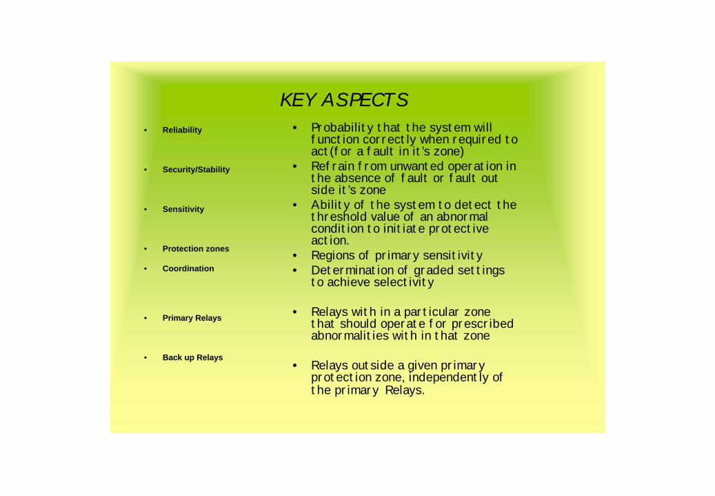
KEY ASPECTS• Reliability
• Security/Stability
• Sensitivity
• Protection zones
• Coordination
• Primary Relays
• Back up Relays
• Probability that the system will function correctly when required to act(for a fault in it’s zone)
• Refrain from unwanted operation in the absence of fault or fault out side it’s zone
• Ability of the system to detect the threshold value of an abnormal condition to initiate protective action.
• Regions of primary sensitivity• Determination of graded settings
to achieve selectivity
• Relays with in a particular zone that should operate for prescribed abnormalities with in that zone
• Relays outside a given primary protection zone, independently of the primary Relays.

Line relaying selection• Criticality of line• Fault clearing time• Line length• Strength of source• Line configuration• Communications• Past practices• Old versus new technology• Future• Re closing requirements• Effect of load in the relay application

EHV line protection : Standard practices
• 220 kV & above– Main-1(Distance)– Main-2(Distance )
- Over voltage(400 kV & above)– Open jumper(400 kV & above)– LBB– Duplicated TEE Differential (In case of 1& ½ breaker scheme
with 5 or 6 CT)– BACK UP O/C FEATURE IN CASE OF FUSE FAILURE– DIRECTIONAL E/F PROTECTION
• 132 kV – One distance – One directional Back Up Over Current– LBB– DIRECTIONAL E/F PROTECTION

Classification of line protection
• Unit protection– Phase comparison (old relays like P40)– Pilot wire differential
• Non Unit protection– Distance protection– Directional over current

Unit protection schemes for lines
• Compares the inflowing and out flowing current in a line– Either as a phase comparison– Or as a differential protection
• Both are available in composite phase or phase segregated
• Phase segregated are suitable as it supports single phase auto reclosing.
• Draw backs: – depends purely on the healthiness of pilot wire– No back up for adjacent lines

Phase comparison relay• Compares the phase relation between the current
entering and leaving the protected zone • Magnitudes are not comparedv Signals are derived from the CT sec currentv Signals send from each end and received at other endv Trip issued in case of absence of signalv During healthy / external fault, Signal send on alternate
half cycle from each end resulting continuous signal –no trip
• During internal fault current in one line reverses,carrier is send only during same half cycle from both ends,resulting in absence of signal for other half cycle –
trip
• ADV: No under reach / over reach

Phase comparison diagram
TRIP
NO TRIP

Pilot wire Differential protection
• Current balanced or voltage balanced• Relay at one end or both ends depending on line
length• Not economical for long lines due to the cost of pilot
wires• Strict supervision of pilot wires required

NON UNIT PROTECTION
v MAIN PARAMETERS
v NON SWITCHED
v MULTI ZONE SETTINGS FACILITY WITHINDEPENDEDNT IMPEDANCE AND TIME SETTINGSFORWARD & REVERSE REACH
v VARIOUS SCHEME OPTIONS (PUR/POR/BLOCKING,TRANSFER TRIP)
v INBUILT POWER SWING BLOCKING , FUSE FAILURE PROTECTION
v INBUILT OPEN JUMPER PROTECTION
v POLIGONAL / MHO CHARACTERISTICS.
v INDEPENDENTLY ADJUSTABLE RESISTIVE AND REACTIVE REACH
v BACK UP O/C FEATURE ON FUSE FAILURE

Tripping characteristics of distance relays
– Plain Impedance– Directional Impedance– Mho Relay– Offset mho Relay– Reactance added MHO relay– Quadrilateral– Lenticular
– RECENT PRACTICE :– MULTIPLE MHO (AT LEAST ONE WITH OFFSET)– QUADRILATTERAL– BOTH NUMERICAL WITH BUILT IN OVER
VOLTAGE,OPEN JUMPER,LBB,FUSE FAILURE , DR

v Affected by arc resistance• Sensitive to power swing
Plain impedance + a directional characteristics which is a straight line through origin (a semicircle)
Dir.Imp
High degree of tolerance to arc resistance
Rectangles of different X/R(improved version of reactance relay)
Quadrilateral
All features of Offset mho and reactanceFor short lines where arc resistance is significant
Circle through origin + a straight line parallel to x axis
Mho+react
Similar to MHOBut less affected by load
Similar to Mho except it is lens shapedLenticular
Suitable for For short lines where arc resistance is significantNon directional
Measures only reactive impStraight line parallel to X axis Reactance
v reverse reach used for back up for station bus barvbetter stability during power swingused as carrier starting element for blocking scheme
Circle passing through originOffset mho
v Stable for Power swingv Under reach during high arc resistance• Preferred for long lines
Circle passing through originStraight line on admittance plane(hence the name)
Mho relay
v Non directional/ Affected by arc resistanceSensitive to power swing
Simple circle with origin of R/X plain as centerPlain IMP
Key features/limitationsfeaturescharacteristics


21 L1 M1 distance
21 L2 M2 Distance
87T1/2 Tee Diff
46 open jumper
59 over voltage
79 A/R
M main/Ch
Energy
meter 21L1- Main-1 dist
21L2 –Main-2 dist
M -M- E/M main
M-C- E/M Check
79 A/R
Typical line prot SLD

Zone-1 settings
v Zone –180 % of protected line Time : Instantaneous
A B
inst Inst
InstDelayInst
delay

ZONE -2 SETTINGSvZone –2vGreater of
120 % of protected line OR100% of protected line + 50% of adj shortest line (If trfrs are there at remote end, Zone 2 should not reach beyond 50% of parallel imp of trfrs to ensure non encroachment to lower volt distribution system)Time (typ) : 200 – 400 msec (coordinate with prim protection of adj line incl CB trip time)
A B
100
50
315 MVA
80

Zone settingZone –3
120 % of (protected line imp + adj longest line)
(If trfrs are there at remote end, Zone 3 should not reach beyond 50-80% of parallel imp of trfrs)Zone –3 rev reach =25% of Z3 forward reach(back up prot for Bus Bar )zone –3 time: 1000 TO 1200 msec

Distance schemes
• Various carrier aided distance schemes are employed with stepped distance characteristicsvDirect under reach transfer trip(DUTT)vPermissive Under Reach Transfer Trip
(PUTT)vPermissive Over Reach Transfer Trip
(POTT)vZone accelerationvBlocking schemevZone –1 extension(Non carrier scheme)

Direct under reach transfer trip(DUTT)
RU OR CR=TRIP
RU CS

PUTT
T2 T2
PERMISSIVE UNDER REACH TRANSFER TRIP
TRIPRURO+CRRO=T2CS --RU

PERMISSIVE OVER REACH TRANSFER TRIP
TRIPRURO+CRCS--RO
RU
RU
RU
RU

ZONE ACCELERATION SCHEME

BLOCKING SCHEME
TRIPRURO+NO BL
LOGIC OF
RU RU


Other protections/features
• LBB– Back up in case of stuck breaker condition– Initiated from all the protections that trip the breaker– Acts if the AC current in the circuit is more than a set limit,for
a set time delay after the protections acted– Trips all the breakers connected to that bus and the remote
end breaker to stop the fault current – Typical setting:– Current 20% of In for all bays other than gen bays
5 % For gen bays – Time delay 200 msec– FOR EHV BAYS OTHER THAN LINE FEEDERS, RETRIP
COMMAND TO THE SAME BREAKER IS ISSUED TO AVOID UNWANTED STATION OUTAGES.
• Open jumper protection:– Detects the negative sequence current– Alarm/ Trip issued when I2 exceeds a set limit and after a set
time delay– Time delay shall be greater than the single phase dead time
of A/R and a considerable margin

• Over voltage– Two stage o/v protection – Stage –1 : 120 % 2-5 sec– Stage –2 : 140 % instantaneous
• Fuse failure protection– Detects the sec fuse failure of VT and blocks the voltage
operated protections– In modern numerical distance relays, VT fuse failure switch on
an O/C feature
• Duplicated TEE differential
– Provided for all the T junctions of breaker and a half scheme– Preferably on two different principle
• One high impedance differential(CAG/RADHA/FAC)• One biased differential(MBCH/RADSB)

Auto reclosing
• Dead time : long enough to completely de-ionise the arc
» TYP 1 SEC FOR FAST A/R 10 SEC FOR DELAYED A/R
• Reclaim time: sufficient for the CB closing mech to reset and get ready for next reclosing mechanism
» TYP 25 SEC
• No of shots : in EHV system single shot preferred as repeated reclosure attempts cause damage
Three phase vs : single phase preferred.single phase
In case of lines emanating from generating station , single phase A/R with Dead line closing at remote end and synchro check at PLANT end is to be adopted.
PRIORITY CLOSING IN CASE OF BREAKER AND A HALF SCHEME TO REDUCE THE STRESS ON TIE CB.
BUILT IN A/R ACCEPTED IN CASE THE FEATURE IS AVAILABLE IN BOTH THE DISTANCE PROTS AND IF AUTOMATIC CHANGE OVER IS POSSIBLE DURING FAILURE.

Practical issues of distance relaying• power swing blocking• Power swing is a 3 ph balanced phenomena• It is the variations in power flow when the generators at various points slip
each other. This could be because of the change in load flow after clearance of a fault.
• The impedance locus during power swing mooves slower that during a fault.
• an outer most zone provided for PSB after the last dist zone , equal to approx 1.3 times the last dist zone
• power swing is detected by monitoring the speed of imp locus • tripping blocked in zone 2 & 3 unblocked in Zone 1(mainly in generating
stations)• Power swing blocking is inhibited when a residual current is detected
( ie, if earth fault occurs during power wing)
• Arc resistance (approx = 2.9x10⁴L / I1.4)• moves the ends of reach impedance to the right of Z plane• Reach of distance relay is reduced due to arc resistance(under reach)• More predominant in short lines as Rarc is considerable to line imp.• Quadrilateral characteristics permits to set resistive reach independently for
each zone/element to take care of arc resistance

Distance Relay Reach
• Under reachØ Impedance presented to the
relay is greater than the fault impedance
§ Uncompensated Earth fault Relay
§ INFEED
• Over reachØ Impedance presented to the
relay is less than the fault impedance
§ Relay applied on Parallel line And one line taken out of service and earthed at each end.
G
HIg Ig+ih
Ih
Vg=Ig X Zl + (Ig+Ih) x ZhAPPARENT IMP= Vg/Ig
= Zl+Zh+(Ih/Ig) X Zh

Current reversal Of Parallel circuits
Current reversal guard stops the permissive and acceleration for a configured time delay after current reversal

SOF Feature

Series compensated lines
A B
`SERIES CAPACITOR INSTALLED IN LINES TO REDUCE THE EFFECTIVE IMPEDANCE AND THUS INCREASE THE POWER FLOWTYPICALLY 35% TO 70%(VALUE OF CAPACITOR AS A PERCENTAGE OF LINEIMPEDANCE) SERIES COMPENSATION IS EMPLOYED. BASICALLY DONE FOR IMPORTANT INTERREGIONAL TIE LINES
ISSUES AT END A
FAULTS BEYOND THE PROTECTED SECTION WILL BE SEEN AS ZONE FAULTS BY RELAY AT A
METHODS USED•DELAYED ZONE-1(ACCOMMODATE THE TIME FOR THE SPARK GAP TO BREAK DURING FAULT)•POR(WITH OUT INDEPENDENT INST Z1)
SC

DISTURBANCE RECORDER
• All EHV lines are provided with Disturbance recorders• Monitors the analogue and digital changes in the circuit and
triggers for a set of such selected changes such as – Threshold values of V/I/F– Rate of change of V/I/F– Operation of all major protections
• Record the wave form for a set time period for pre-fault, fault and post fault conditions.
• Sampling frequency 1000 – 2000Hz• Gen practice is to have individual Data acquisition units for
various bays and a common evaluation unit• The record obtained from DR can be played back to the
relays through dynamic relay test kits like Omicron , Pulsar etc to test the performance of the relays
• Recent Numerical Distance relays have built in DR meeting most of the requirements.(MICOM ,REL 7SA series )

Commonly used relays
VARM111
CAGCDGCTU
VAG,VDG,VTU
MCTI,CTIG
MM3TQUADRA MHO (quad)OPTIMHO(quad)MICHROMHO(Multiple mho)NUM RELAYEPAC/MICOM SERIES WITH BUILT IN LBB/AR/OPEN JUMPER/OV/DR/FL
ALSTOM
7 RW
7 VK
7 SJ
PART OF DIST
7 SV
7 SA SERIES
SIEMENS(NUM .RELAYS)
FCN
RAAAM
RXIG
RXEG
RAICA
RALZB (wave det+imp)RASFE(quad+mho)LZ 96(NUMERICAL RELAY:REL SERIES WITH IN BUILTIN LBB,O/V, A/R/OPEN JUMPER/DR/FL(Multiple Characteristics)
ABB
AUTORECLOSE
FREQUENCY RELAY
CURRENT RELAY
VOLTAGE RELAY
LBB
Distance protections
Protection


PHASE COMPARISION SCHEME

Parallel circuits Effect of mutual coupling
• Z= ZL {1+ (KOM*IEp)/(Iph* K0*IE) }
• Error is proportional to the mutual coupling factorKOM =ZOM /3 ZL
v Error increases with the parallel line earth current IEP
v Relay under reaches when IEP is in phase with Iph and IE
v Relay over reaches when IEP Iph and IE has opposite signs.