eh 10204 e rev b - fagerberg construction offers a contoured plug (21100 series)with a threaded seat...
TRANSCRIPT

MASONEILAN¨
21000 Series Control ValvesInstructions
InstructionNo EH 10204 ERév. B - 03/98
INSTRUCTIONMANUAL

Instruction No EH 10204 ERev. B - 03/98
2
l. INTRODUCTION .....................................................2
2. GENERAL ...............................................................2
3. UNPACKING ............................................................3
4. INSTALLATION ........................................................3
5. AIR PIPING ..............................................................3
6. BODY DISASSEMBLY .............................................36.1 THREADED TRIM............................................36.2 QUICK-CHANGE TRIM....................................4
7. MAINTENANCE/REPAIR .........................................47.1 THREADED SEAT RING REMOVAL ...............47.2 BUSHING REMOVAL.......................................47.3 LAPPING SEATS .............................................4
7.3.A THREADED TRIM .................................47.3.B QUICK-CHANGE TRIM.........................5
7.4 LO-DB PLUG....................................................57.5 PLUG STEM PINNING.....................................57.6 PACKING BOX.................................................6
7.6.1 KEVLAR/PTFE PACK. RING(STANDARD).........................................6
7.6.2 EXPANDED GRAPHITE P. RING(OPTION) .............................................7
7.6.3 LE PACKING (LOW EMISSION) (OPTION) ..............................................7
7.7 SOFT SEAT PLUG ...........................................8
8. VALVE BODY REASSEMBLY .................................98.1 THREADED TRIM............................................9
8.2 QUICK-CHANGE TRIM....................................9
9. ACTUATORS ..........................................................119.1 TYPES 87/88 ACTUATORS ...........................11
9.2 TYPES 47/48 ∑F ACTUATORS .....................11
9.3 TYPES 37/38 ACTUATORS ...........................11
9.3.1 ACTUATOR REMOVAL .......................119.3.2 ACTUATOR ASSEMBLY ANDADJUSTMENT .................................................11
ALL FIGURES ....................................3, 10, 13, 14 & 15
1. lntroductionThe following instructions should be thoroughlyreviewed and understood prior to installing, operatingor performing maintenance on this equipment.Throughout the text, safety and/or caution notes willappear and must be strictly adhered to, otherwise,serious injury or equipment malfunction could result.
Masoneilan has a highly skilled After Sales Departmentavailable for start-up, maintenance and repair of ourvalves and component parts.Arrangements for this service can be made through yourlocal Masoneilan Representative or After SalesDepartment. When performing maintenance use onlyMasoneilan replacement parts. Parts are obtainablethrough your local Masoneilan Representative or SpareParts Department. When ordering parts always includeModel and Serial Number of the unit being repaired.
2. GeneralThese installation and maintenance instructions apply toall sizes and ratings of the Masoneilan 21000 Seriescontrol valves regardless of the type of trim used.
21000 Series single ported top guided control valves aredesigned with built in versatility making them well-suited tohandle a wide variety of process applications.
Standard construction offers a contoured plug (21100Series) with a threaded seat ring or a quick change seatring. The heavy top plug guiding provides maximumsupport to ensure plug stability.
A series of reduced area trim is available to provide wideflow range capabilities in all valve sizes.
Tight Shutoff Class IV leakage is standard. Optionalconstructions (one of which is the 21600 Series soft seat
plug) meet IEC 534-4 and ANSI/FCI 70.2 Class V and Vlrequirements.
An optional Low Emission LE Packing is available toassure compliance with the fugitive emission containmentrequests.
Replacing the conventional plug with the single stageLO-DB design (21700 Series) provides excellent noiseattenuation or cavitation control.
The 21800 Series double stage anticavitation valve isderived from the 21700 single stage anticavitation valvethrough a modification to the cage and plug. Substitutionof the standard cage with an anticavitation cage permitsthe pressure drop to be split between the two stagesefficiently.
The 21900 Series double stage LO-DB valve is alsoderived from the 21700 single stage LO-DB valve througha modification to the cage and plug. Substitution of thestandard cage, with a LO-DB cage permits the pressuredrop to be split between the two stages efficiently.
In 21800/900 Series designs, enlargement of the plughead up to the cage diameter permits simultaneousthrottling of the plug Cv and the cage Cv. It also providesoptimum allocation of the pressure drop between the twostages along the entire plug travel.
Recommended spare parts required for maintenance arelisted in Parts Reference on page 14. The model number,size, rating and serial number of the valve are shown onthe identification tag located on the actuator. Refer toFigures 1 for 21000 series numbering system.
Table of content

Instruction No EH 10204 ERev. B - 03/98
3
3. Unpacking
Care must be exercised when unpacking the valve toprevent damage to the accessories and component parts.Should any problems arise, contact the local MasoneilanRepresentative or After Sales Department.
4. lnstallation
4.1 Before installing the valve in the line, clean pipingand valve of all foreign material such as weldingchips, scale, oil, grease or dirt. Gasket surfacesshould be thoroughly cleaned to insure leak-proofjoints.
4.2 To allow for in-line inspection, maintenance orremoval of the valve without service interruption,provide a manually operated stop valve on each sideof the 21000 Series valve with a manually operatedthrottling valve mounted in the by-pass line. (SeeFigure 2).
4.3 The valve must be installed so that the controlledsubstance will flow through the valve in the directionindicated by the flow arrow located on the body.
• With contoured plug (21100/600) or LO-DB plug (21700/900) :flow-to-open
• On anticavitation design (21700/800) :flow-to-close
4.4. In case of a heat-insulated installation, do notinsulate the valve bonnet and take protectionmeasures related to personal safety.
5. Air Piping
The actuators are designed to accept 1/4” NPT air supplypiping. Use 1/4” OD tubing (4 x 6 mm) or equivalent for allair lines. If the supply air line exceeds 25 feet in length (7meters) or if the valve is equipped with volume boosters,3/8” tubing (6 x 8 mm) is preferred. AII connections must befree of leaks.
Caution : Do not exceed supply pressure indicated onserial plate on the yoke of actuator.
6. Body Disassembly
Access to the internal components of the body should beaccomplished with the actuator removed. To remove theactuator from the body, refer to the actuator instruction NoER8788E for a type 87/88 multispring actuator, NoER20004E for a type 47/48 ∑F actuator, or to Section9.3.1 of this manual in case of a 37/38 spring diaphragmactuator.
Caution: Prior to performing maintenance on the valve,isolate the valve and vent the process pressure. Shutoff the supply air line and pneumatic or electric signalline.
6.1 Threaded Trim (Figure 12 or 14)
After removing the actuator, disassemble the body usingthe following procedure:
A. If a leak detection circuit is connected on thelateral NPT port of the bonnet, disconnect the pipefrom this one.
B. Remove body stud nuts (10).
C. Remove bonnet (8), plug stem (1) and plug (16)together as one unit.
Note: Spiral wound body gaskets (11) are standard inthe 21000 Series design and it is imperative that anew gasket be installed each time the valve isdisassembled.
D. Remove packing flange stud nuts (3), packingflange (4) and packing follower (5).
E. Remove plug (16) and plug stem (1) from thebonnet (8).
Caution: Care must be taken to avoid damage tothe plug and plug guide.
Actuator Type Body Series Plug TypeControl
Characteristics Seat Type
0. Undefined1. Unbalanced
contoured6. Unbalanced
Soft Seat7. Single Stage
LO-DB/Anti-cavitation
8. Double StageAnticavitation
9. Double StageLO-DB
0. Undefined1. Linear*2. Equal Percentage*3. Modified Percentage +
21
If valve with type 47/48 actuator,available only with positioner
*
Only on valve with type 47/48 actuator +
37 Spring DiaphragmAir-to-Close
38 Spring DiaphragmAir-to-Open
47 Spring DiaphragmAir-to-Close
48 Spring DiaphragmAir-to-Open
87 Spring DiaphragmAir-to-Close
88 Spring DiaphragmAir-to-Open
1st 2 nd 1st 2 nd 3 rd 4 th 5 th
2 1
0. Undefined4. Quick Change5. Threaded
Figure 1Numbering System

Instruction No EH 10204 ERev. B - 03/98
4
F. Remove old packing (6) [and optional lanternring (7) if a leak detection circuit has been installed].Refer to Figure 5.
G. Bonnet (8), plug (16), bushing (12) and seatring (14) may now be inspected for wear and servicedamage. After determining the maintenance required,proceed to the appropriate Section of theseinstructions.
6.2 Quick-Change Trim (Figure 13 or 15)
After removing the actuator, disassemble the body usingthe following procedure:
A. If a leak detection circuit is connected on thelateral NPT port of the bonnet, disconnect the pipefrom this one.
B. Remove body stud nuts (10).
C. Remove bonnet (8), plug stem (1) and plug (16)together as one unit.
D. Since the cage (13), seat ring (14) and seat ringgasket (15) are held in place by the bonnet, they maynow be removed.
Note: In case of a 900-1500-2500 ANSI Class valve,a gasket (15) is provided between the cage (13) andthe bonnet (8). See Figure 16.
Note: Spiral wound gaskets (11 & 15) are standard inthe 21000 Series design and it is imperative that newgaskets be installed each time the valve isdisassembled.
E. Remove packing flange stud nuts (3), packingflange (4) and packing follower (5).
F. Remove plug (16) and plug stem (1) from thebonnet (8).
Caution: Care must be taken to avoid damage tothe plug and plug guide.
G. Remove old packing (6) [and optional lanternring (7) if a leak detection circuit has been installed].Refer to Figure 5.
H. All components may now be inspected for wearand service damage. After determining themaintenance required, proceed to the appropriateSection of this instruction manual.
7. Maintenance/Repair
The purpose of this section is to assist maintenancepersonnel by suggesting methods of componentmaintenance which is largely dependent on the tools andmachine shop equipment available.
7.1 Threaded Seat Ring Removal (Figure 12 or 14)
Threaded seat rings (14) are installed tightly at thepoint of manufacture and after years of service, theyare often difficult to remove.
To facilitate removal, seat ring wrenches can befabricated to engage the seat ring lugs and adapted toa shock wrench. If the ring is exceptionally resistant toremoval, the application of heat or penetrating oilshould be helpful.
Caution: When using heating devices, insure thatproper safety practices are observed. Such itemsas the flammability and toxicity of the controlledsubstance must be considered and properprecautions taken.
7.2 Bushing Removal
The bushing (12) is a press fit into the bonnet anddoes not normally require replacement. If necessary, itmay be pulled or machined out. When machining thebushing out, care must be taken to maintain properdimensions and tolerances. These will be furnishedupon request.
7.3 Lapping Seats
Lapping is the process of working the valve plugagainst the seat ring, with an abrasive, to produce aclose fit. When valve leakage becomes excessive,lapping becomes necessary. The plug and seat ringseating surfaces should be free of large scratches ordents and the contact surfaces of the seats should beas narrow as possible. This may require dressing bothparts in a lathe. The seating surface of the plug is 28degrees and that of the seat ring is 30 degrees(relative to the centerline axis). For the lappingoperation, a good grade of fine grinding compound isrequired.
The compound should be mixed with a small quantityof lubricant such as graphite. This will slow the cuttingrate and prevent tearing of the seating surfaces. Theamount of lapping required depends on the materials,condit ion of seating surfaces and accuracy ofmachining. lf a short period of lapping does not visiblyimprove seating, there is usually no advantage incontinuing as too much lapping may result in roughseats. The only remedy is replacement or re-machiningof one or both parts. When lapping new plug and seatring, begin with medium compound and finish with fine.
Caution : Before lapping, plug and stem must betrue. (See pinning operation, item 7.5).
7.3.A Threaded Trim (Figure 12 or 14)
(1) CIean body gasket surface areas.
(2) When seat has been removed, insure that thesealing surface in the body bridge and the threadsare thoroughly cleaned.
Note: A sealant compatible with the processshould be applied sparingly to the seat ringthreads and sealing shoulder.
(3) lnstall and tighten seat ring using fabricatedwrench used for removal.

Instruction No EH 10204 ERev. B - 03/98
5
Caution: Do not over-tighten. Do not strikedirectly seat ring lugs. This could distort theseat ring result ing in unwarranted seatleakage.
(4) Apply lapping compound at several spotsequally spaced around the seating area of theplug.
(5) lnsert the stem and plug assembly carefullyinto the body until it is seated.
(6) Place bonnet (8) on the body and fasten thebonnet to the body using four body stud nuts (10),spaced equally apart, apply slight pressure andtighten evenly.
Caution: Do not t ighten nuts to torquespecifications at this time. The bonnet is usedtemporarily for guiding purposes only.
(7) lnsert two or three pieces of packing (6) intothe packing box to assist in guiding the stem andplug during lapping.
(8) Screw a drilled and tapped rod with a T-handleon to the plug stem and secure with a locknut.(See Figure 4).
Note: As an alternative, drill a hole through a flatpiece of steel and fasten to the plug stem usingtwo locknuts.
(9) Applying a slight pressure on the stem, rotatethe stem in short oscillating strokes, 8 to 10 times.Repeat this step as necessary.
Note: The plug should be lifted and turned 90°between repeating Step (9). This intermittentlifting is required to keep the plug and seat ringconcentric during lapping.
(10) After completion of the lapping operation,remove bonnet and plug. The seat area of theseat ring and the plug must be cleaned of alllapping compound in preparat ion forreassembly. Don’t remove seat ring.
7.3.B Quick-Change Trim (Figure 13 or 15)
(1) CIean body gasket surface areas.
(2) Install a new seat ring gasket (15) and insertseat ring (14) in the body.
Note: Gasket (15) is temporarily placed to holdthe seat ring during lapping.It is imperative to use a new gasket or a falsepart having the same geometricalcharacteristics in order to insure the correctposition of the seat ring during lapping.This gasket (or similar part) can be kept afterlapping for future use.The gasket used for lapping must not bereused for the body reassembly.
(3) Apply grinding compound at several spotsequally spaced around the seating area of theseat ring.
(4) lnsert the cage (13) into the body.
(5) lnsert the stem and plug assembly carefullyinto the body until it is seated.
(6) PIace bonnet (8) on the body.
Caution: Insure that the seat ring (14), cage(13) and bonnet (8) are properly aligned.
(7) Fasten the bonnet to the body using four bodystud nuts (10), spaced equally apart, apply slightpressure and tighten evenly.
Caution: Do not t ighten nuts to torquespecifications at this time. The bonnet is usedtemporarily for guiding purposes only.
(8) Insert two or three pieces of packing into thepacking box to assist in guiding the stem and plugduring lapping.
(9) Screw a drilled and tapped rod with a T-handleon to the plug stem and secure with a locknut.(See Figure 4).
Note: As an alternative, drill a hole through a flatpiece of steel and fasten to the plug stem usingtwo locknuts.
(10) Applying a slight pressure on the stem, rotatethe stem in short oscillating strokes 8 to 10 times.Repeat this step as necessary.
Note: The plug should be lifted and turned 90°between repeating Step (10). This intermittentlifting is required to keep the plug and seat ringconcentric during lapping.
(11) After completion of the lapping operation,remove bonnet and internal parts. The seatarea of the seat ring and the plug must becleaned of all lapping compound in preparationfor reassembly.
7.4 LO-DB PIug (Figure 8, 14 or 15)
The procedures used for performing maintenance on avalve equipped with LO-DB plug (21700/800/900 Series)are the same as those used for Threaded or QuickChange Trim.
Caution: Maintenance of the plug should be limited tocleaning of the ports and the maintenance ormachining which may be required under Section 7.3,Lapping and 7.5, Pinning.
7.5 PIug Stem Pinning
Plug stem pinning during field assembly may be dividedinto two parts:
— Replacing old plug and old stem,
— Replacing only old stem,
Replacing Plug and Stem
If it is necessary to replace the plug, then the plug stemmust be replaced at the same time. The original pin hole inan old stem will not provide satisfactory results and mightseriously impair strength of the assembly.

Instruction No EH 10204 ERev. B - 03/98
6
A. Reference Marking on the Plug Stem
Measure the depth of the pilot recess in the plug (X inFigure 9) and make a reference mark to the plug stem atthe same distance, from the thread.
B. Screwing Stem into Plug
• Hold the plug guide in a vise.
• Lock one nut against another one to the end of the newplug stem and, using a wrench on the upper nut, screwthe stem solidly into the plug.When properly assembled, the reference mark (seesection A above) should be flush with the end of theguide section.
C. Drilling the New Parts
• If the plug is already full drilled, (in case of 440 Cstainless steel, hardened material or solid stellite), thendrill the stem to the same diameter as the plug skankhole.
• If the plug guide area has a center mark,
PIace the plug guide on a V-block and, using a size ofdrill bit suitable to either,— match the hole size in the plug, or— match the “C” diameter (see Figure 9),
drill the plug-stem assembly.
• If the plug guide area does not have any hole or anycenter mark,
— Measure the “D” dimension according to plug guidediameter and stem diameter, (see Figure 9).
— PIace the plug guide on a V-block and, by means ofa center punch, make a center mark on the plugguide area.
— Using a suitable size drill bit, drill the plug-stemassembly.
In all cases: After drilling, remove any burrs from the plugguide by making a slight chamfer.
D. Pinning the Plug-Stem Assembly
1. Select the correct size pin according to plug guidediameter and stem diameter (see Figure 9). Apply asmall amount of grease on it, and hand place the pinto the hole inlet.
2. By means of an hammer, introduce the pin into thehole. Complete the pinning operation, taking care toensure that the pin is recessed by the same amount atboth sides, (see Figure 9).
3. After the plug has been pinned, it should be placed ina lathe to insure it is running “true.”
The stem should be placed in a collet with the plugguide against it and the plug should be struck.Alignment of plug stem can be performed by means ofa soft faced mallet.
Replacing Only Old Stem
A. Removing Old Pin and Stem From the Plug
1. Place the plug guide on a V-block, and using a driftpunch, drive out the old pin.
Note: If it is necessary to drill out the pin, a drill bitsomewhat smaller than the pin should be used andthe remainder of the pin driven out.
2. Hold the plug guide in a vise, (see bordered note inthe above paragraph A.
3. Lock one nut against another at the end of the plugstem. Using a wrench on the lower nut, unscrew thestem from the plug. The stem is removed by turning itanti-clockwise.
B. Screwing Stem to Plug
Refer to paragraph B of the above chapter “REPLACINGPLUG AND STEM”.
C. Drilling the New Stem
PIace the plug guide on a V-block and, using a suitablesize drill bit, drill the stem using the hole in the plug as aguide.
Note: If the hole in the plug guide has been slightlydamaged while removing of the old pin, choose a drill bitand a pin with a diameter somewhat larger than thenormal pin.
D. Pinning
Select the correct size pin according to the plug guidediameter and pin hole diameter. Proceed as described inpart D of the previous section, taking care not to damagethe plug guide area.
Ensure plug stem alignment following pinning operation.
7.6 Packing Box (Figures 12 to 15)
Packing box maintenance is one of the principleaction items of routine servicing. Tightness of thepacking is maintained by packing compression.Compression is achieved by evenly tightening thepacking flange nuts (3) against the packingflange (4). Care must be taken not to over tighten asthis could prevent smooth operation of the valve. Ifall compression is used up and the valve leaks, newpacking is required.
Caution: Valve must be isolated an the pressurevented before performing packing boxmaintenance.
Proceed as follows:
7.6.1 Kevlar/PTFE Rings (Standard) (Figures 12 to15)
Note: The Kevlar/PTFE packing rings have a skivecut allowing packing replacement without disconnectthe plug stem from actuator connector or actuatorstem.
A. Loosen and remove packing flange nuts (3).
Note: While pinning is being performed, care mustbe taken not to damage the seating surface or plugguide. Always use a soft metal or plastic vise jawswith a cylindrical machining to hold the plug guidearea (see Figure 9).

Instruction No EH 10204 ERev. B - 03/98
7
B. Raise packing flange (4), and packing follower(5) up the valve stem.
Note: They may be taped in place to keep themout of the way before proceeding.
C. By means of a hook remove packing (6),insuring not to damage the sealing surface ofpacking box or plug stem.
Note: On valve equipped with an optional leakdetection connection, the lantern ring (7) mustalso be removed.
D. Replace packing rings (6).
Note: Cram rings one by one into packingbox. The skive cut of each packing ring mustbe placed about 120 degrees apart.
Note: On valves equipped with an optional leakdetection connection, refer to Figure 10 forcorrect amount of rings to place under the lanternring (7).
E. Replace packing follower (5) and packingflange (4).
F. Replace and tighten packing stud nuts (3).
Caution: Do not overtighten.
G. Put valve back in service and tighten packingonly as much as is necessary to stop leaking.
Note: In an emergency, string packing may beused as a temporary repair only. It must bereplaced with the correct packing as soon aspossible.
7.6.2 Expanded Graphite Rings (Optional)(Figure 6)
Note: Expanded graphite packing rings replacementrequires disconnecting the plug stem from theactuator connector or actuator stem and removal ofthe actuator.
A. Remove actuator from the body S/A. Refer toactuator instruction No ER8788E for a type 87/88actuator and No ER20004E for a Type 47/48 ∑FActuator. Refer to Section 9.3.1 Actuator Removalin this instruction for a Type 37/38 SpringDiaphragm Actuator.
B. Loosen and remove packing flange nuts (3).
C. Remove packing flange (4), and packingfollower (5) from the plug stem.
D. By means of a hook remove packing (6),insuring not to damage the sealing surface ofpacking box or plug stem.
Note: On valve equipped with an optional leakdetection connection, the lantern ring (7) must alsobe removed.
E. Replace new packing set (6); first one back-upring (Carbon/Graphite/Inconel braided ring), thenexpanded graphite rings (smooth rings), andfinally another braided back-up ring. (Refer toFigure 6).
Note: Cram rings one by one into packingbox.
Note: On valve equipped with an optional leakdetection connection, refer to Figure 10 forcorrect arrangement according to valve size.
F. Place packing follower (5) and packing flange (4).
G. Assemble and tighten packing stud nuts (3).
Caution: Do not overtighten.
H. Proceed to appropriate instructions foractuator and valve assembly adjustment.
I. Place valve back in service and tighten packingonly as much as is necessary to stop leaking.
7.6.3 (Low Emission) PACKING™ (Optional)(Figure 7)
The Masoneilan LE Packing is a high performancepacking system capable of containing fugitive emissionswell below the specif ications of the most severerecommendations. It is also available in a firesafe design.
The packing is provided as a set of five pieces. Itconsists of two adapter rings and three V-rings, analternating pattern of Perfluoroelastomer (PFE) andlong carbon fiber filled Teflon (PTFE) V-rings areused.
This packing, applied properly, exhibits very little coldflow (or creep). Consequently, it can prevent themajor cause of fugitive emissions from a controlvalve. The LE Packing system can directly replaceconventional packing, requiring no modification to thecontrol valve or actuator.
A spring loaded, two-piece follower assembly isused to maintain a constant load on the packing,and is necessary for thermal cycling applications. Asthe definition of thermal cycling can vary, andprocesses are potentially subject to unpredictedthermal gradient, LE Packing is only available withthe spring loaded follower.
Installation should be performed as detailed inthe following paragraphs
7.6.3.1. Preparation
7.6.3.1.1 Stem
Inspect stem for any nicks or scratches andquality of finish. Reject the stem for any of thesereasons as they may damage packing.
Note: A properly etched part number on thestem in the packing area will have no adverseeffect on the performance of the packing.
Stem finish should be 3-7 AARH finish degree,(Ra 0,1/0,2).
7.6.3.1.2 Packing Box
Note: Bonnets that have a leak detection holeor lube hole are unacceptable for use with thepreferred packing arrangement shown inFigure 7.
Note: Packing box finish should be conform to125 AARH finish degree (Ra 3,2), or better.
Packing box should be clean and free ofburrs, rust and any foreign matter. Partscan be cleaned with denatured alcohol.
Instruction No EH 10204 ERev. B - 03/98
8
The packing box may be bored or honed oversizeby up to 0,38 mm (0.015”) above the nominaldiameter to improve the finish. For instance, anominal 22,22 mm (0.875”) packing box may bebored or honed up to 22,60 mm (0.890”) and theLE Packing will still seal properly.
Pack ing box mus t be f i n i shed to thebottom of the bore.
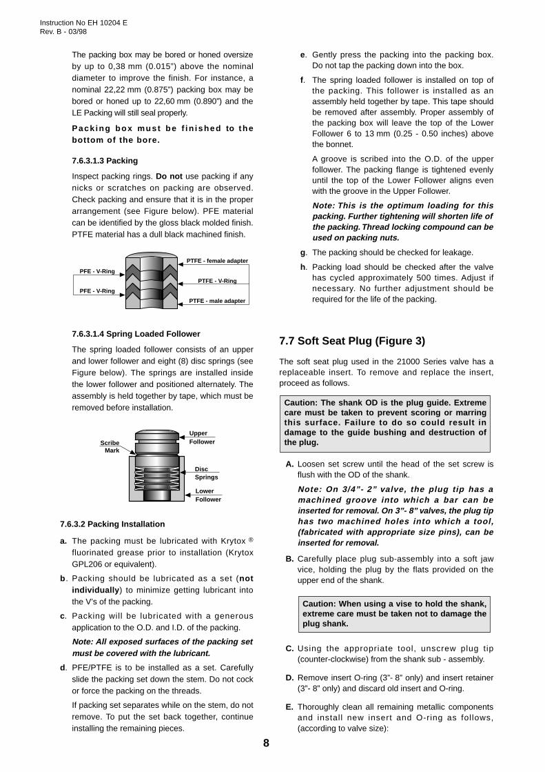
7.6.3.1.3 Packing
Inspect packing rings. Do not use packing if anynicks or scratches on packing are observed.Check packing and ensure that it is in the properarrangement (see Figure below). PFE materialcan be identified by the gloss black molded finish.PTFE material has a dull black machined finish.
7.6.3.1.4 Spring Loaded Follower
The spring loaded follower consists of an upperand lower follower and eight (8) disc springs (seeFigure below). The springs are installed insidethe lower follower and positioned alternately. Theassembly is held together by tape, which must beremoved before installation.
7.6.3.2 Packing Installation
a. The packing must be lubricated with Krytox ®
fluorinated grease prior to installation (KrytoxGPL206 or equivalent).
b . Packing should be lubricated as a set (notindividually ) to minimize getting lubricant intothe V’s of the packing.
c. Packing will be lubricated with a generousapplication to the O.D. and I.D. of the packing.
Note: All exposed surfaces of the packing setmust be covered with the lubricant.
d. PFE/PTFE is to be installed as a set. Carefullyslide the packing set down the stem. Do not cockor force the packing on the threads.
If packing set separates while on the stem, do notremove. To put the set back together, continueinstalling the remaining pieces.
e. Gently press the packing into the packing box.Do not tap the packing down into the box.
f. The spring loaded follower is installed on top ofthe packing. This follower is installed as anassembly held together by tape. This tape shouldbe removed after assembly. Proper assembly ofthe packing box will leave the top of the LowerFollower 6 to 13 mm (0.25 - 0.50 inches) abovethe bonnet.
A groove is scribed into the O.D. of the upperfollower. The packing flange is tightened evenlyuntil the top of the Lower Follower aligns evenwith the groove in the Upper Follower.
Note: This is the optimum loading for thispacking. Further tightening will shorten life ofthe packing. Thread locking compound can beused on packing nuts.
g. The packing should be checked for leakage.
h. Packing load should be checked after the valvehas cycled approximately 500 times. Adjust ifnecessary. No further adjustment should berequired for the life of the packing.
7.7 Soft Seat Plug (Figure 3)
The soft seat plug used in the 21000 Series valve has areplaceable insert. To remove and replace the insert,proceed as follows.
A. Loosen set screw until the head of the set screw isflush with the OD of the shank.
Note: On 3/4”- 2” valve, the plug tip has amachined groove into which a bar can beinserted for removal. On 3”- 8” valves, the plug tiphas two machined holes into which a tool,(fabricated with appropriate size pins), can beinserted for removal.
B. Carefully place plug sub-assembly into a soft jawvice, holding the plug by the flats provided on theupper end of the shank.
C. Using the appropriate tool, unscrew plug tip(counter-clockwise) from the shank sub - assembly.
D. Remove insert O-ring (3”- 8” only) and insert retainer(3”- 8” only) and discard old insert and O-ring.
E. Thoroughly clean all remaining metallic componentsand install new insert and O-ring as follows,(according to valve size):
Caution: When using a vise to hold the shank,extreme care must be taken not to damage theplug shank.
Caution: The shank OD is the plug guide. Extremecare must be taken to prevent scoring or marringthis surface. Failure to do so could result indamage to the guide bushing and destruction ofthe plug.
UpperFollower
LowerFollower
DiscSprings
ScribeMark
PTFE - female adapter
PTFE - V-Ring
PTFE - male adapter
PFE - V-Ring
PFE - V-Ring

Instruction No EH 10204 ERev. B - 03/98
9
For 3/4”- 2” valves :
a. Place new insert on shank and insert retainer asshown in Figure 3.
b. Install plug tip into shank sub-assembly handtighten and insure plug tip seats evenly againstinsert.
For 3” - 8” valves :
a. Apply a light coat of lubricant to the O-ring andinstall on insert retainer.
b. Install new insert on insert retainer, assembling asshown in Figure 3.
c. Install plug tip into insert retainer sub - assemblyinsuring the plug tip seats evenly on the insert.
F. Carefully place the plug sub-assembly into a soft jawvise, holding the plug by the flats provided on theupper end of the shank.
G. Using the appropriate tool used during disassembly,firmly tighten the plug tip.
H. After following the above tightening sequence,securely tighten set screw. Plug is ready for assemblyinto a valve.
8. Valve Body Reassembly
After completion of the required maintenance the valveshould be reassembled using the following procedures :
Note: If any of the following steps were completed duringmaintenance, proceed to the next step.
8.1 Threaded Trim (Figure 12 or 14)
A. CIean all gasketed surfaces.
B. Apply a small amount of sealant to the seat ringthreads and sealing shoulder and install.
Note: A sealant compatible with the process should beapplied sparingly .
C. lnstall and tighten seat ring using wrench used forremoval.
Caution: Do not over-tighten. Do not strike seatring lugs directly. This could distort the seat ringresulting in unwarranted seat leakage.
Note: Valve should be lapped before final assembly.See Section 7.3.A.
D. Carefully install plug and stem assembly.
E. Install body gasket (11).
Note: Spiral wound body gaskets (11) are standard inthe 21000 Series design and it is imperative that a newgasket be installed each time the valve isdisassembled.
F. Install bonnet (8) and body stud nuts (10). Bonnetmust be positioned so the packing flange studs are ata right angle to the flow center line.
Caution: Tighten nuts (10) until metal to metalcontact is obtained with proper bolt torque. Referto Figure 11 for proper bolt torque and tighteningsequence specifications.
G. lnsert packing (6) [and lantern ring (7) on valveequipped with an optional leak detection connection].Refer to Section 7.6 to apply proper order andprocedure for packing box filling (standard or optionaldesign).
H. Install packing follower (5), and packing flange (4).
I. lnstall packing flange stud nuts (3).
Caution: Do not overtighten (See Section 7.6“Packing Box”).
J. If a leak detection circuit was installed, connect it onthe lateral NPT port of the bonnet. If not, insure thatthe 1/4” NPT plug is remained in place. (Figure 5).
K. For actuator to body assembly and plug stemadjustment, proceed to the actuator instruction NoER8788E for a type 87/88 actuator, No ER20004E fora type 47/48 ∑F actuator, or to Section 9.3.2 of thismanual for a 37/38 spring diaphragm actuator.
8.2 Quick-Change Trim (Figure 13 or15)
A. CIean all gasketed surfaces.
B. Install seat ring gasket (15) and seat ring (14).
Note: Spiral wound gaskets (11 & 15) are standard inthe 21000 Series design and it is imperative that a newgasket be installed each time the valve isdisassembled.
C. Install cage (13).
D. Carefully install plug and stem assembly.
Note: Valve should be lapped before final assembly.See Section 7.3.B.
E. Install body gasket (11).
Note: In case of a 900-1500-2500 ANSI Class valves,a gasket (15) is provided between the cage (13) andthe bonnet (8). See Figure 16.
Caution: The plug tip must be tightened,allowed to set for approximately 4 hours,re-tightened, allowed to set for 4 hours, thentightened one more time. The aim for thistightening sequence is to allow the insertmaterial to “cold flow” into place on the plugsub-assembly.
Caution: When using a vise to hold the shank,extreme care must be taken not to damage theplug shank.
Caution: Insure any lubricant used iscompatible with service conditions.

Instruction No EH 10204 ERev. B - 03/98
10
7
Lantern Ring1/4” NPT
Plug
Figure 2 – Typical Installation
Figure 4 – Lapping Seats Device
Insert
3/4”-2” Valve Sizes 3”-8” Valve Sizes
InsertRetainer
PlugTip
Plug Tip O-ring
ShankSkirt &InsertRetainer
SetScrewSet
Screw
Figure 5 – Leak Detection Connection (Optional)
BraidedBack-up Rings
ExpandedGraphite
Rings
Figure 6 – Expanded Graphite Rings Arrangement(Optional)
Packing SetPFE/PTFE5 pieces
SpringLoadedFollower S/A
Figure 7LE (Low Emission) Packing Arrangement (Optional)
Figure 8LO-DB (Type 21900) and Anticavitational (Type 21800)
Two-Stages Trim (Optional)
Figure 3 – Soft Seat Plugs (Optional)

Instruction No EH 10204 ERev. B - 03/98
11
F. Install bonnet (8) and body stud nuts (10) andtighten. Bonnet must be positioned so the packingflange studs are at a right angle to the flow center line.
Caution: Care must be taken to assure that thecage, seat and bonnet are properly aligned in thebody. Tighten nuts (10) until metal to metal contactis obtained with proper bolt torque. Refer to Figure11 for proper bolt torque and tightening sequencespecifications.
G. lnsert packing (6) [and lantern ring (7) on valveequipped with an optional leak detection connection].Refer to Section 7.6 to apply proper order andprocedure for packing box filling (standard or optionaldesign).
H. Install packing follower (5) and packing flange (4).
I. Install packing flange stud nuts (3).
Caution: Do not overtighten (See Section “7.6.Packing Box”).
J. If a leak detection circuit was installed, connect it onthe lateral NPT port of the bonnet. If not, insure thatthe 1/4” NPT plug is remained in place. (Figure 5).
K. For actuator to body assembly and plug stemadjustment, proceed to the actuator instruction NoER8788E for a type 87/88 multispring actuator, NoER20004E for a type 47/48 ∑F actuator, or to Section9.3.2 of this manual for a 37/38 spring diaphragmactuator.
9. Actuators
9.1 Types 87/88 ActuatorsRefer to Instruction No ER 8788 E for removal,maintenance, assembly and adjustment.
9.2 Types 47/48 ∑F ActuatorsRefer to Instruction No ER 20004 E for removal,maintenance, assembly and adjustment.
9.3 Types 37/38 Actuators (Figure 17)Refer to Instruction No ER 30004 E for themaintenance. For removal, assembly and adjustment,see the below Sections.
9.3.1 Actuator Removal.
Sizes No 9, 11 & 13
Air-to-Extend Actuator (Type 37)
1. Shut off air supply pressure and disconnect air linesat the actuator. Loosen stem locknuts (22), turn themdown to the threaded end of plug stem (1) and lock. Fora size No 13, disengage the locking plate (55) fromactuator stem (26).
2. By means of a wrench applied over the locknuts,turn the plug stem (1) out of actuator stem (26).
Note: In case of lower plug stroke, [during this operationand after removing drive nut (19)], it may be necessaryto lift the actuator while unscrewing plug stem, becausethe length engaged into actuator stem is larger than thevalve stroke.
3. After the pIug stem is unscrewed and actuatorremoved, remove locking plate (55), locknuts (22) andtravel indicator (23) from the plug stem.
Air-to-Retract Actuator (Type 38)
1. Retract actuator stem (26) and plug by applying airpressure. Loosen stem locknuts (22), turn them downuntil threaded end of plug stem (1) and lock. For a sizeNo 13, disengage the locking plate (55) from actuatorstem (26).
2. By means of a wrench applied over the locknuts,turn the plug stem (1) out of actuator stem (26).
Note: In case of lower plug stroke, [during this operationand after removing drive nut (19)], it may be necessaryto lift the actuator while unscrewing plug stem, becausethe length engaged into actuator stem is larger than thevalve stroke.
3. After the pIug stem is unscrewed and actuatorremoved, remove locking plate (55), locknuts (22) andtravel indicator (23) from the plug stem. Shut off airpressure and disconnect air lines at the actuator.
Sizes No 15, 18 & 18L
Air-to-Extend Actuator (Type 37)
Shut off air supply and disconnect air lines at theactuator. Remove nut (53), screw (52) andclamps (51). Unscrew drive nut (19), then removeactuator from the valve.
Air-to-Retract Actuator (Type 38)
Retract actuator stem and plug by applying airpressure. Remove nut (53), screw (52) andclamps (51). Unscrew drive nut (19), then removeactuator from the valve. Shut off air pressure anddisconnect air lines at the actuator.
9.3.2 Actuator Assembly and Adjustment
Sizes 9, 11 & 13
1. Push plug stem (1) down until the plug seats, thenreplace locknuts (22) and travel indicator (23) (andlocking plate (55) on No 13 actuators).
2a. Air-to-Extend Actuator (Type 37) :
• Install actuator on bonnet with drive nut (19). Turnplug stem (1) into actuator stem (26) as far as it willgo.
Caution: Do not allow the plug to turn on the seatduring this operation.
Caution: Do not allow the plug to turn on the seatduring this operation.
Instruction No EH 10204 ERev. B - 03/98
12
• Connect a temporary supply air line on actuator.Apply maximum air pressure of spring rangestamped on serial plate. Turn plug stem out ofactuator stem until plug is seated. Relieve airpressure and unscrew plug stem (1) an additionalhalf turn out of actuator stem (26).
• Tighten stem locknuts (22) against actuator stem [orlocking plate (55)]. Relieve air pressure, then adjusttravel indicator scale (56). Travel indicator (23)should indicate “open” when air pressure is relieved.
2b. Air-to-Retract Actuator (Type 38) :
• Connect a temporary supply air line on actuator.Admit sufficient air pressure to retract actuator stemto full stroke. Install actuator on bonnet with drivenut (19).
• Turn plug stem (1) into actuator stem (26) as far as itwill go. Relieve air pressure until minimum of springrange stamped on serial plate.
Turn plug stem out of actuator stem until plug isseated. Increase air pressure and turn plug stem anadditional one full turn out of actuator stem.
• Tighten stem locknuts (22) against actuator stem [orlocking plate (55)]. Relieve air pressure, then adjusttravel indicator scale (56). Travel indicator (23)should indicate “closed” when air pressure isrelieved.
Sizes No 15, 18 & 18L
1. Push plug stem (1) down until the plug seats.
2a. Air-to-Extend Actuator (Type 37) :
• Install actuator on bonnet with drive nut (19).Connect a temporary supply air line on actuator.Apply maximum air pressure of spring rangestamped on serial plate.
• Install the stem clamps (51) and travel indicatorpointer (23). The amount of thread engagement ofboth stems should be approximately equal. Slightlytighten clamp nut (53). Relieve air supply pressure.
• Unscrew plug stem (1) a half turn out of stemclamps (51). Tighten clamp nut (53), then adjusttravel indicator scale (56) in regard of the indicatorpointer (23). Travel indicator pointer (23) shouldindicate “open” when air pressure is relieved.
2b. Air-to-Retract Actuator (Type 38):
• Connect a temporary supply air line on actuator.Admit sufficient air pressure to retract actuator stemto full stroke. Install actuator on bonnet with drivenut (19).
• Relieve air pressure to minimum of spring rangestamped on serial plate. Install stem clamps (51) andtravel indicator pointer (23). Slightly tighten clamp nut(53). The amount of thread engagement of bothstems should be approximately equal.
• Increase pressure and turn plug stem an additionalone full turn out of stem clamps (51). Tighten clampnut (53), relieve air pressure then adjust travelindicator scale (56) in regard of the indicatorpointer (23). Travel indicator pointer (23) shouldindicate “closed” when air pressure is relieved.
Caution: Do not allow the plug to turn on theseat during this operation.
Caution: Do not allow the plug to turn on theseat during this operation.
Caution: Do not allow the plug to turn on theseat during this operation.
Caution: Do not allow the plug to turn on theseat during this operation.

Instruction No EH 10204 ERev. B - 03/98
13
Plug StemDia. “B”
Pin HoleDia. “C” “D” “X”
mm in. mm in. mm in. mm in.
12,70 1/2 3,50 .138 32 1.25 13 .50
12,70 1/2 3,50 .138 32
1.88
13 .50
Plug GuideDia. “A”
mm
22,22
38,10
19,05 3/4 5,00 .197 47,5
1.25
19 .75
19,05 3/4 5,00 .197 47,5 1.88 19 .75
60,32
69,85
==Soft metalor plasticvise jaws
Cylindrical machiningdiameter of the jaws =plug guide diameter “A”
C Dia.D
XX
AB
ValveDia. Kevlar/PTFE
mm in. Above Total
20 to 100 3/4 to 4 6
150 6 7
Expanded Graphitew/ backup Rings
Below
200 8 8
Quantity of Packing Rings (6)Packing box with Kevlar/PTFEpacking rings
LanternRing(7)
Packing box with Expanded Graphite packing rings
and Back-up rings
BraidedBack-up Rings
ExpandedGraphite Rings
LanternRing(7)
Lantern Ring (7)Above Total
6
7
Below
8
Lantern Ring (7)
ValveDia.
mm in.
25 - 40 1 - 1 1/2900 31230 250 34
Min.daN.m
Carbon Steel Studs
Max.Ft. Lbs.daN.mFt. Lbs.
ANSI ClassStud (9)
20 to 50 3/4 to 2150 - 300400 - 600
4,533 37 51/2” -13 NC - 2A
200 8 150 - 300 26192 207 281 1/4” - 8 NC - 2A
1
2
34
5
6 7
81
2
34
1
2
34
10
8
5
67
11
12
9
1
2
3
5
6
4
Size Qty
8
12
1500 35260 295 401” - 8 NC - 2A 42500 40295 370 50
5,540 48 6,5
80 3150300
400 - 600
860 63 8,55/8” -11 NC - 2A 6
19140 148 203/4” -10 NC - 2A 8
100 4150 - 300400 - 600
8,563 70 9,55/8” -11 NC - 2A 828207 220 301” -8 NC - 2A 8
150 6150 - 300400 - 600
8,563 66 95/8” -11 NC - 2A 1228207 221 301” -8 NC - 2A 12
860 63 8,55/8” -11 NC - 2A 6
23170 184 25
Min.daN.m
Stainless Steel Studs
Max.Ft. Lbs.daN.mFt. Lbs.
3,526 30 4
26192 207 28
4,533 37 5
23 *170 * 184 * 25 *752 59 828207 221 30
966 74 10
Req’d. Torque
28207 221 30 * Only on 21000 threaded trim valves. For quick-change trim valves, use following torques.........
Figure 10 – Packing Rings Arrangements on Packing Box with Optional Leak Detection Connection
Figure 11 — Torques Sequences and Values for nuts (10)
Figure 9Plug Stem Pinning
Instruction No EH 10204 ERev. B - 03/98
14
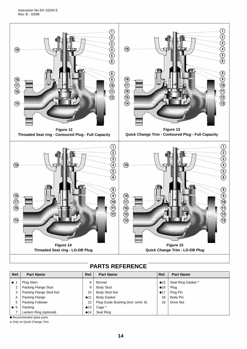
Figure 14Threaded Seat ring - LO-DB Plug
Figure 15Quick Change Trim - LO-DB Plug
PARTS REFERENCE
● Recommended spare parts
* Only on Quick Change Trim
● 1 Plug Stem
2 Packing Flange Stud
3 Packing Flange Stud Nut
4 Packing Flange
5 Packing Follower
● 6 Packing
7 Lantern Ring (optional)
8 Bonnet
9 Body Stud
10 Body Stud Nut
● 11 Body Gasket
12 Plug Guide Bushing (Incl. w/ref. 8)
●13 Cage *
●14 Seat Ring
●15 Seat Ring Gasket *
●16 Plug
●17 Plug Pin
18 Body Pin
19 Drive Nut
Ref. Part Name Ref. Part Name Ref. Part Name
1
2
3
4
5
6
8
9
10
11
12
19
18
17
16
14
Figure 12Threaded Seat ring - Contoured Plug - Full Capacity
1
2
3
4
5
6
8
9
10
11
12
13
19
18
17
16
15
14
Figure 13Quick Change Trim - Contoured Plug - Full Capacity
1
2
3
4
5
6
8
9
10
11
12
19
18
17
16
14
1
2
3
4
5
6
8
9
10
11
12
13
19
18
17
16
15
14

Instruction No EH 10204 ERev. B - 03/98
15
26 56
Stem ConnectorType Accordingto Actuator Size
(See Detail)
26
56
Type 37Air to Extend Actuator
Type 38Air to Retract Actuator
22
23
1
26
55
22
23
1
26
51
23
1
53
52
57
26
Stem Locknuts(On No 9 & 11
Spr. Diaph. Actuators)
Stem Lock(On No 13 Spr.
Diaph. Actuator)
Split Stem Clamp(On No 15, 18 & 18L
Spr. Diaph. Actuators)
Detail of the Three Stem Connector Types
Figure 17Types 37/38 Masoneilan
Spring-Diaphragm Actuators
1 Plug Stem22 Locknut23 Travel Indicator (pointer)26 Actuator Stem51 Stem Clamp52 Hex. Head Screw53 Clamp Nut55 Locking Plate56 Travel Indicator Scale57 Screw
Ref. Part Name
11
15
Figure 1621000 Series
3/4” to 2” Valve Sizes900, 1500, 2500 ANSI Class

AUSTRIAMasoneilan HP+HP GmbHHans-Kudlich-Strasse 35A 2100 Korneuburg (b.Wien), AustriaTelephone : 43-2262-63689Fax : 43-2263-68915
BELGIUMMasoneilan Division of Dresser Europe S.A.281-283, Chaussée de Bruxelles1190 BRUSSELS - BelgiumTelephone : 32-2-344-0970Fax : 32-2-344-1123
BRAZILDresser Idustria E Comercio LtdaDivisao MasoneilanRua Senador Vergueiro, 43309521-320 Sao Caetano Do SulSao Paolo - BrazilTelephone : 55-11-453-5511Fax : 55-11-453-5565
CANADAOntarioDresser Canada, Inc.Valve Division5010 North Service RoadBurlington, Ontario,L7L 5R5 - CanadaTelephone : 1-905-335-3529Fax : 1-905-336-7628
AlbertaDresser Canada, Inc.Valve Division#300, 444-58th Avenue S.E.Edmonton, Alberta T6E 6J2 - CanadaTelephone : 1-780-463-4888Fax : 1-780-465-1244
FRANCEDresser Produits IndustrielsDivision Masoneilan4 Place de Saverne92971 Paris La Défense CedexFranceTelephone : 33-1- 49 04 90 00Fax : 33-1-49 04 90 10
Lyon Distribution Center55, rue de la Mouche69540 Irigny - FranceTelephone : 33-4-72 39 06 29Fax : 33-4-72 39 21 93
Martigues Distribution CenterAzur II - La Palunette13220 Chateauneuf-les-MartiguesFranceTelephone : 33-4-42 76 17 24Fax : 33-4-42 79 87 52
GERMANYHead Office : Masoneilan - HP+HP GmbHKlein-Kollenburg-Strasse 78-8047877 Willich, GermanyTelephone : 49-2156-9189-0Fax : 49-2156-41058
Frankfurt : Masoneilan - HP+HP GmbHUhlandstrasse 58 -60314 Frankfurt - GermanyTelephone : 49-69 439350Fax : 49-69 4970802
Leuna : Masoneilan - HP+HP GmbHGoethestrasse 170006237 Leuna - GermanyTelephone :Fax : 49-03461 434443
INDIADresser Valve India Pvt, Ltd305-306 "Midas" - Sahar PlazaMathurdas Vasanji RoadJ.B. Nagar - Andheri East Mumbai 400 059 - IndiaTelephone : 91-22-835-4790Fax : 91-22-835-4791
ITALYDresser Italia S.p.A. Masoneilan Operation
Headquarters, Sales Office, Plant and AfterSales : Via Cassano 7780020 Casavatore (Naples) - ItalyTelephone : 81-7892-111Fax : 81-7892-208
North Italy Sales Office :C.soGaribaldi 11320121 Milan - ItalyTelephone (02) 29005683/84Fax (02) 29005660
JAPANNiigata Masoneilan Company, Ltd26th floor, Marive East TowerWBG 2-6 Nakase, Mihama-kuChiba-shi, Chiba, 261-71 - JapanTelephone : 81-43-297-9242Fax : 81-43-299-1115
KOREADresser Korea, Inc#2107 Kuk Dong Building60-1, 3-Ka, Choongmu-roChung-Ku, Soeul 100705 - KoreaTelephone : 82-2-274-0792Fax : 82-2-274-0794
KUWAITDresser Valve Division - Middle East OperationsP.O. Box 242Safat 13003 - KuwaitTelephone : 965-9061157
Mailing adress :Flat No. 36, Floor 8Gaswa Complex, MahboulaKuwait
MEXICOMasoneilan Internacional, S.A. de C.v.Henry Ford n° 114, Esq. FultonFraccionamiento Industrial San Nicolas54030 Tlalnepantla - Estado de MexicoTelephone : 52-5-310-9863Fax : 52-5-310-5584
THE NETHERLANDSDresser Industrial Products B.V.Masoneilan DivisionSteenhouwerstraat 113194 AG HoogvlietTelephone : 31-10-438-4122Fax : 31-10-438-4443
Mailing adress :P.O. Box 640NL-3190 AN Hoogvliet RTThe Netherlands
SINGAPOREDresser Singapore Pte LtdValve Division16, Tuas Avenue 8 - Singapore 639231Telephone : 65-861-6100Fax : 65-861-7172
SOUTH AFRICADresser Ltd, South Africa BranchValve DivisionP.O. Box 2234 - 16 Edendale RoadEastleigh, Edenvale 1610Transvaal, Republic of South AfricaTelephone : 27-11-452-1550Fax : 27-11-452-6542
SPAINMasoneilan S.A.Zona Franca - Sector M, Calle Y08040 Barcelona - SpainTelephone : 34-93-223-4175Fax : 34-93-223-4754
SWITZERLANDDresser Europe SAFrauentalweg 76CH-8045 Zurich, SwitzerlandTelephone : 41-1-450-2891Fax : 41-1-450-2895
Mailing adress :P.O. Box 3568CH-8021 Zurich, Switzerland
UNITED ARAB EMIRATESDresser Valve DivisionPost Box 61302Jebel Ali Free ZoneUnited Arab EmiratesTelephone : 971-4-838-752Fax : 971-4-838-038
Mailing adress :Units Nos JAO1 + JAO2Roundabout 8Jebel Ali Free ZoneUnited Arab Emirates
UNITED KINGDOMValve DivisionDresser U.K. LimitedTrevithick WorksGillibrands Estate, SkelmersdaleLancashire WN8 9TU - EnglandTelephone : 44-1695-52600Fax : 44-1695-52662
Valve DivisionU.K. Southern Sales Office :Unit 5, Brook Business CentreCowley Mill Road, UxbridgeMiddlesex UB8 2FX - EnglandTelephone : 44-1895-454900Fax : 44-1895-454919
UNITED STATESNorthern RegionValve DivisionDresser Equipment Group, Inc85 Bodwell StreetAvon, Massachusetts 02322-1190Telephone : 1-508-586-4600Fax : 1-508-427-8971
Southern RegionValve DivisionDresser Equipment Group, Inc11100 West Airport Blvd.Stafford, Texas 77477-3014Telephone : 1-281-568-2211Fax : 1-281-568-1414Toll Free : 1-800-847-1099
Dresser Equipment Group, Inc15112 Morales Road (77032)P.O. Box 60078Houston, Texas 77205-0078Telephone 1-281-871-6500Fax 1-281-871-6569
LATIN AMERICADresser Valve & Controls Division10556 NW 26th Street, Suite D-201Miami, Florida 33172 - U.S.A.Telephone 1-305-470-2766Fax 1-305-470-2743
Sales Officesand Distribution
Centers
PLANTS, SPARE PARTS and AFTER SALESDEPARTMENTS :3 Rue Saint–Pierre - 14110 Condé–sur–NoireauTelephone : 33-2-31 59 59 59 - Fax : 33-2-31 59 59 60Doc.Technique MN – Condé