egr486bawaproject1report.pdf
TRANSCRIPT

CNC
Project #1
Rajan Bawa(1206587040)
[CNC PROJECT #1] Creating an efficient, production style Haas CNC mill program to machine the billet connecting rod.
Topic Covered
1. Introduction
2. Connecting Rod and Blank Material
3. Machine Used for the Operation
4. Part Routing/Job Planning
5. Operation Used
• Operation#1
a) Tooling used
b) OP#1 Milling Operation
c) The resulting Part Obtained
d) FAIR Inspection Report
• Operation#2
a) Tooling Used
b) FAIR Inspection Report
6. Conclusion
7. Difficulties Encountered
8. Appendix
• OP#1 Setup Sheet
• OP#2 Setup Sheet
• CMM Inspection Report
Note: Most of the Images used are either obtained from work or copied from Google images
(with Interactive 3D MOdel)
Page (1-2)
Page(2-3)
Page 3
Page 4
Page(5-10)
Page 11
Page 12
Page (13-17)
Introduction:
Maximizing the use of manufacturing resources is one of the major concerns of manufacturing.
It is important because we have to manufacture a product within its tolerance limit while giving
a consideration to its cost and complexity of its design. Manufacturing industries have been
using integrated CAD/CAM system for the past few decades to explore efficient ways of
manufacturing a product in order to reduce existing problems associated with tool wear, waste
stream and most importantly, to achieve a desirable Metal Removal Rate (MRR) while working
under the physical constraints set by industries.
The HSM solid works is a CAM software and is widely used to create an efficient Hass mill
program to machine the product, like Billet connecting rod. HSM works is used to simulate
number of machining operations, some of which includes, face milling, drilling, Adaptive
clearing, contour milling, radius cutting, chamfering, and other finishing operations. The
objective of using HSM is to avoid tool jamming, reduce machining time and achieve desired
tolerance limit.
The standardized CAM process, like the one we have used for designing Billet Connecting rod
significantly increases performance, as it reduces the programming time, even while one is
coding for complex geometries. With built in tool libraries, one can set optimal feeds and speed
to match with materials and tools used for CNC operation. This eliminates the need to calculate
the cutting speeds and feed rates every time a different tool is introduced within a program.
Moreover, HSM works helps in designing an efficient code for Billet Connecting rod and ensures
that all the codes are presented cleanly and in preferred order, which is very helpful. For an
Page 1

instance, we can easily make simple modification in a machine, if required (e.g. edit the code,
feed speed and cutting speed etc.). This increases the performance and reduces machine cycle,
which further results in more efficient, safe and less costly operation. Thus the Billet Connecting
rod designed using HSM works presents a quality work at each stage of its operation.
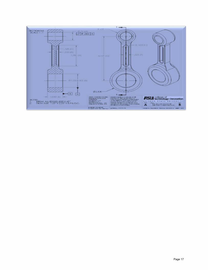
Connecting Rod:-
The report emphasizes the methodology and analysis of designing a Billet Connecting Rod. The
goal is to build a connecting rod which is within its tolerance limit. The Rod is made from 6061-
T6 AL which is a hardening Aluminum alloy and perfectly suits for the machining that we will do
on it using Hass CNC machine.
Fig. The Connecting Rod
Page 2
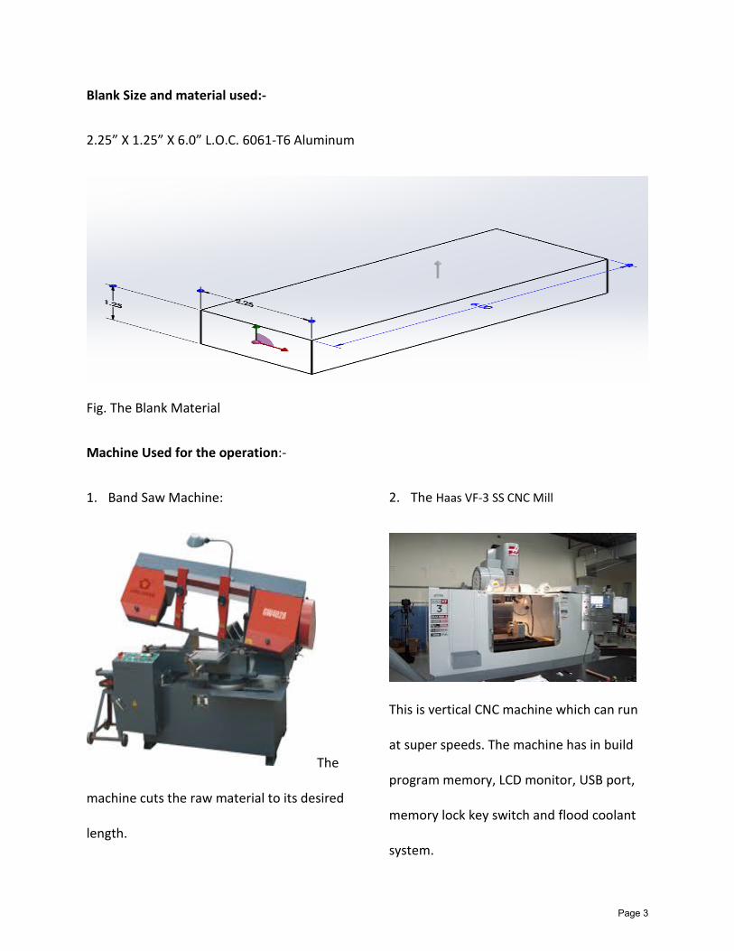
Blank Size and material used:-
2.25” X 1.25” X 6.0” L.O.C. 6061-T6 Aluminum
Fig. The Blank Material
Machine Used for the operation:-
1. Band Saw Machine: 2. The Haas VF-3 SS CNC Mill
The
machine cuts the raw material to its desired
length.
This is vertical CNC machine which can run
at super speeds. The machine has in build
program memory, LCD monitor, USB port,
memory lock key switch and flood coolant
system.
Page 3

Part Routing/Job Planning:
The Part Routing/ Job planner gives details of all the operations. This will including everything
from Band saw cutting, CNC mill operations, Inspection and many others. Below is the table
that list the details:-
Page 4

Operation Used
1.Operation #1
Tooling Used:
• T1 = H1 = 3.0” 6-Flute Carbide Insert Face Mill• T3 = H3 = 0.750” 4 Flute Carbide End Mill• T4 = H4 = 0.250” 4 Flute Carbide Ball Mill• T5 = H5 = 0.250” 2 Flute HSS Chamfer Tool• T6 = H6 = 0.625” 2 Flute Carbide Drill• T7 = H7 = 0.500 2 Flute Carbide End Mill• T8 = H8 = 0.125” 4 Flute HSS Radius Cutter• T24 = Edge Finder• Kurt Vise& Hard Steel Jaws• 1-5/8” Machinist Parallels
OP #1 Milling Operations:-
All of this operations are designed using HSM works. Below are the steps that were simulated
using CAM software to design an efficient mill code for connecting rod:
• Face Milling: This operation uses face of the cutting tool to machine the top flat surface. The
cutter of 3-inch diameter is lowered to certain depth and then set to engage to the work
piece. One thing that should be given consideration in this tool path is, to extend the cutter
across the surface before it retracts.
• Adaptive Roughing: This operation uses the outside periphery of cutting tool to machine the
surface. The process uses ¾-inch of a flat mill for cutting around outside surface of the part.
This operation is used to remove the maximum material from the sides and shapes the
material to its approximate finished form. The metal removal is done until one reaches the
farthest possible surface, and the major reason for doing this is to avoid thin layer
formation, which could possibly cause failure by wrapping across the tool. Secondly,
Roughing also helps in saving time.
Page 5
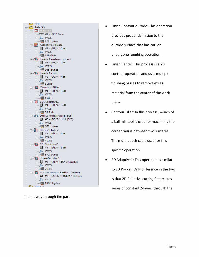
find his way through the part.
• Finish Contour outside: This operation
provides proper definition to the
outside surface that has earlier
undergone roughing operation.
• Finish Center: This process is a 2D
contour operation and uses multiple
finishing passes to remove excess
material from the center of the work
piece.
• Contour Fillet: In this process, ¼-inch of
a ball mill tool is used for machining the
corner radius between two surfaces.
The multi-depth cut is used for this
specific operation.
• 2D Adaptive1: This operation is similar
to 2D Pocket. Only difference in the two
is that 2D Adaptive cutting first makes
series of constant Z-layers through the
Page 6

• Drilling and Boring: These two operations are performed in sequence. The drilling process
creates holes; where as boring operation enlarges the hole to the required diameter.
• Chamfer and radius cutting:-The operation uses tool#7 and tool#8 for doing their operation.
The resulting part obtained after Milling:
Page 7
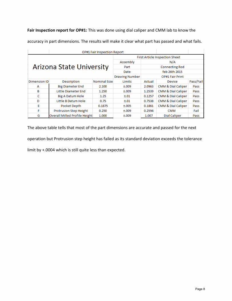
Fair Inspection report for OP#1: This was done using dial caliper and CMM lab to know the
accuracy in part dimensions. The results will make it clear what part has passed and what fails.
The above table tells that most of the part dimensions are accurate and passed for the next
operation but Protrusion step height has failed as its standard deviation exceeds the tolerance
limit by +.0004 which is still quite less than expected.
Page 8
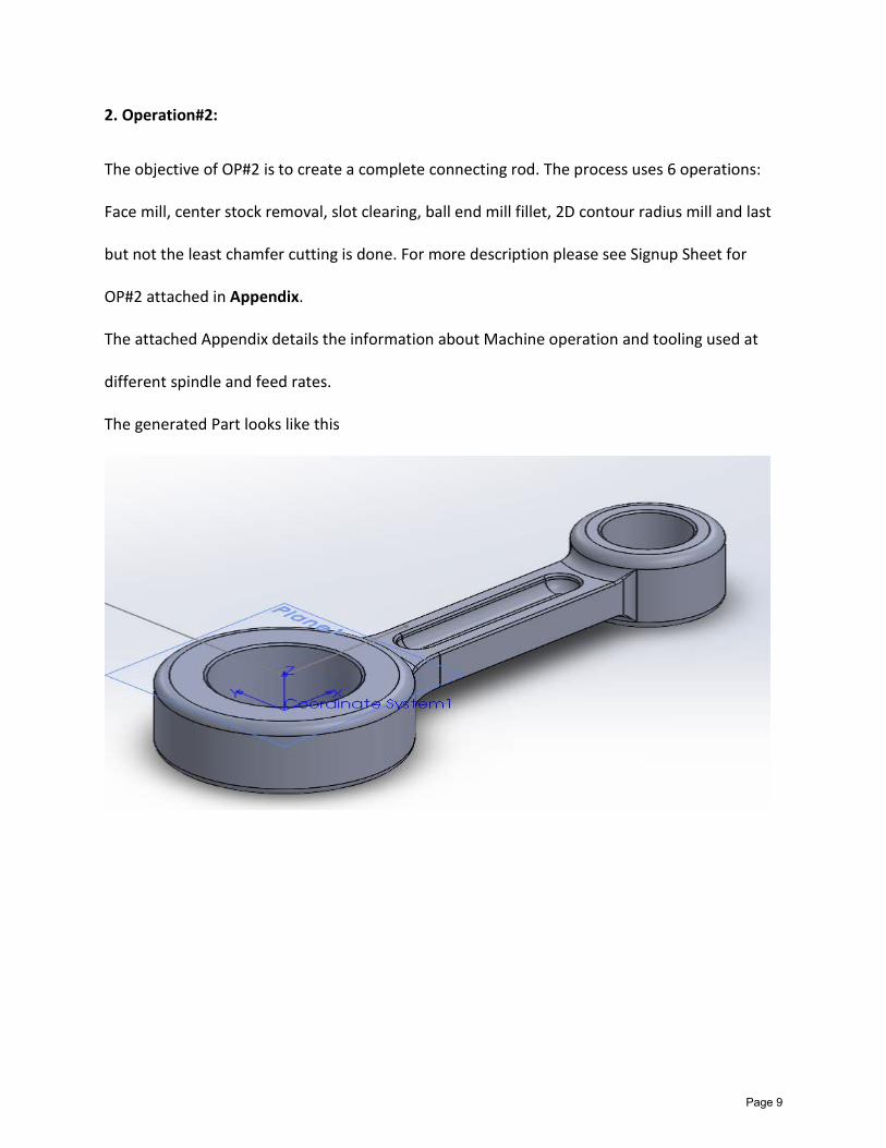
2. Operation#2:
The objective of OP#2 is to create a complete connecting rod. The process uses 6 operations:
Face mill, center stock removal, slot clearing, ball end mill fillet, 2D contour radius mill and last
but not the least chamfer cutting is done. For more description please see Signup Sheet for
OP#2 attached in Appendix.
The attached Appendix details the information about Machine operation and tooling used at
different spindle and feed rates.
The generated Part looks like this
Page 9

Tooling used for OP#2:-
• 3” 6 Flute carbide Insert face mill
• ¾” 4 Flute carbide end mill center cutting 1.0” L.O.C.
• ¼” 4 Flute carbide Ball End Mill, 50” L.O.C.
• ¼” carbide 25 Degree Chamfer Tool 4-Flute
• R.125” Corner Round Tool 4-Flute
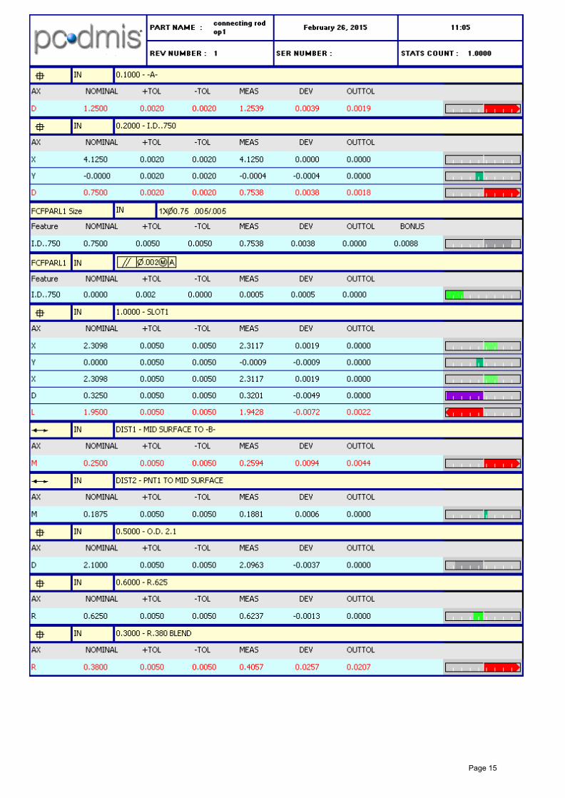
Inspection Report for OP#2 :-
The Co-ordinate Measuring Machine (CMM) is used to measure the physical geometry of the
Connecting rod to check whether the resulting dimensions lie within the tolerance limit.
Page 10
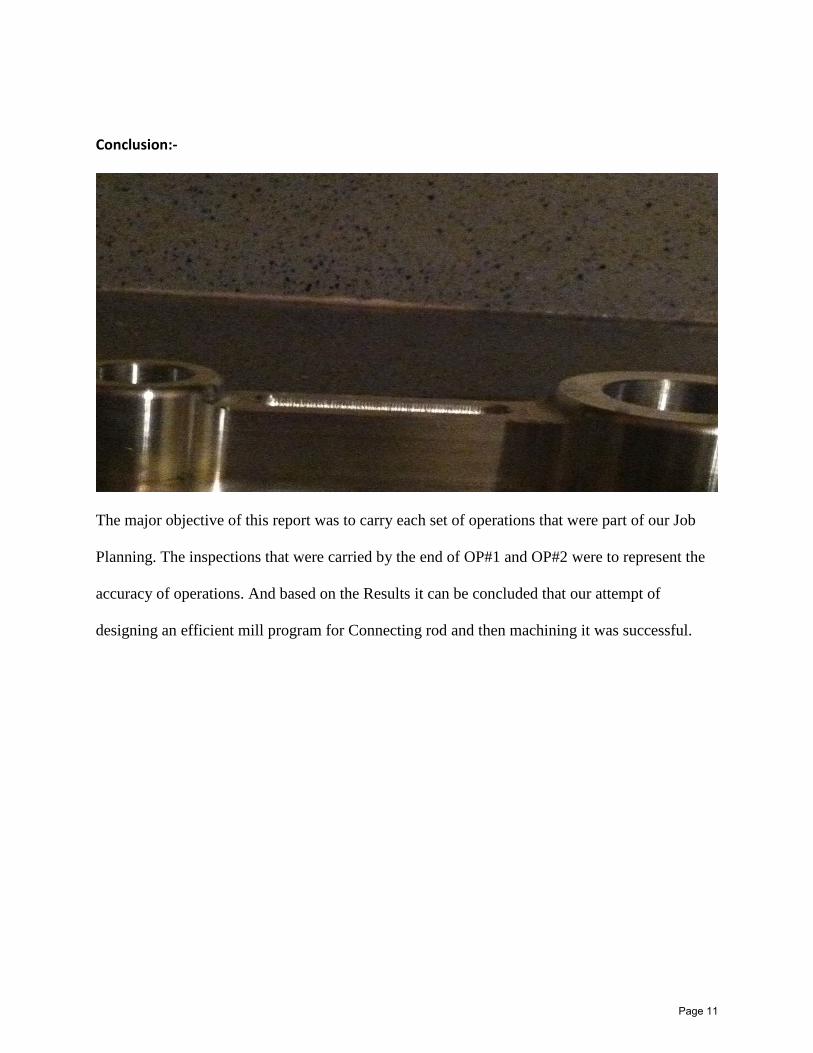
Conclusion:-
The major objective of this report was to carry each set of operations that were part of our Job
Planning. The inspections that were carried by the end of OP#1 and OP#2 were to represent the
accuracy of operations. And based on the Results it can be concluded that our attempt of
designing an efficient mill program for Connecting rod and then machining it was successful.
Page 11

Difficulties encountered:-
Despite the fact that we are using advance CAM system such as HSM works, which make
designing a machine code easier but user has to be really efficient in dealing with the complex
drawings. While most of our operations were designed with ease, but we had faced difficulties
while working along the profiles that had curvatures.
Page 12
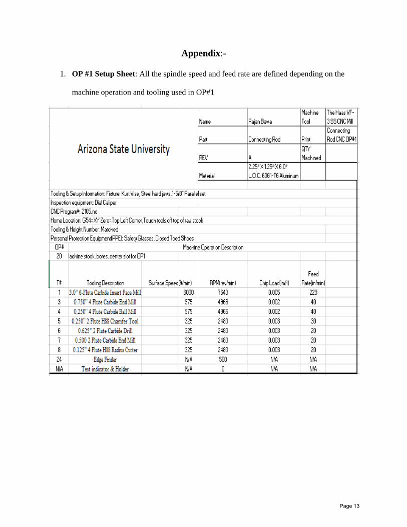
Appendix:-
1. OP #1 Setup Sheet: All the spindle speed and feed rate are defined depending on the
machine operation and tooling used in OP#1
Page 13

2. OP #2 Setup Sheet: All the spindle speed and feed rate are defined depending on the machine
operation and tooling used in OP#2
Page 14
Page 15

Page 16


Page 17