egate tutorial - oracle help center€¦ · · 2003-10-15egate tutorial 2 seebeyond proprietary...
TRANSCRIPT
eGate Tutorial
Release 5.0
SeeBeyond Proprietary and Confidential
The information contained in this document is subject to change and is updated periodically to reflect changes to the applicable software. Although every effort has been made to ensure the accuracy of this document, SeeBeyond Technology Corporation (SeeBeyond) assumes no responsibility for any errors that may appear herein. The software described in this document is furnished under a License Agreement and may be used or copied only in accordance with the terms of such License Agreement. Printing, copying, or reproducing this document in any fashion is prohibited except in accordance with the License Agreement. The contents of this document are designated as being confidential and proprietary; are considered to be trade secrets of SeeBeyond; and may be used only in accordance with the License Agreement, as protected and enforceable by law. SeeBeyond assumes no responsibility for the use or reliability of its software on platforms that are not supported by SeeBeyond.
SeeBeyond, e*Gate, and e*Way are the registered trademarks of SeeBeyond Technology Corporation in the United States and select foreign countries; the SeeBeyond logo, e*Insight, and e*Xchange are trademarks of SeeBeyond Technology Corporation. The absence of a trademark from this list does not constitute a waiver of SeeBeyond Technology Corporation's intellectual property rights concerning that trademark. This document may contain references to other company, brand, and product names. These company, brand, and product names are used herein for identification purposes only and may be the trademarks of their respective owners.
© 2003 by SeeBeyond Technology Corporation. All Rights Reserved. This work is protected as an unpublished work under the copyright laws.
This work is confidential and proprietary information of SeeBeyond and must be maintained in strict confidence.
Version 20031015170944.
eGate Tutorial 2 SeeBeyond Proprietary and Confidential

Contents
Contents
Chapter 1
Introduction 5Organization of Information 5
Supporting Documents 5
Writing Conventions 6
eGate Installation Requirements 6
The SeeBeyond Web Site 7
Chapter 2
Features of the Enterprise Designer 8Enterprise Designer Components 8
Menu Bar 9
Enterprise Explorer 10
Project Editor 10
Chapter 3
Building a Simple Project 11Business Challenge 11
Project Overview 12Project Description 12Process Overview 13
Create the Sample Data 15Create the Sample Input XML File 15Create the Input.dtd File 15Create the Output.dtd File 16
Create a New Project 16
Create a Connectivity Map 18
Add Components to the Connectivity Map 19Add Components to the Connectivity Map 19
eGate Tutorial 3 SeeBeyond Proprietary and Confidential
Contents
Create a New Object Type Definition 21
Configure the Services 26Configure Timecard_to_topic 26Apply Business Rules for TimecardToTopic_collab 30Configure Topic_to_Payroll_out 34Apply Business Rules for TopicToPayrollOut_collab 38
Apply the Collaborations 46Link Components in the Connectivity Map 47
Configure the eWays and JMS Connections 49
Create Environment and Activate the Deployment Profile 52Create a New Deployment Profile 54Deploy your Project 56
Run the Bootstrap and Management Agent 57
Verify the Output Data 58
Enterprise Manager Overview 59When to Use the Monitor 60Using Project View 60Using Environment View 60Locating the Problem Node 60
Starting and Using Enterprise Manager 60Monitor a Collaboration in your Connectivity Map 61Stop Service 62Monitor Alerts 62Check Log Messages 63
Glossary 65
Index 71
eGate Tutorial 4 SeeBeyond Proprietary and Confidential
Chapter 1
Introduction
Welcome to the eGate Tutorial. The Tutorial must be run on a Windows system.
This document includes an overview of the Enterprise Designer graphical user interface (GUI) and tutorial to help you learn how to create and run a Project in eGate Integrator.
This chapter includes
! “Organization of Information” on page 5
! “Supporting Documents” on page 5
! “eGate Installation Requirements” on page 6
! “The SeeBeyond Web Site” on page 7
1.1 Organization of InformationThis document includes the following chapters:
! Chapter 1 “Introduction” overviews the contents of the eGate Tutorial, describes the writing conventions used in this document, and provides a complete list of related eGate Integrator documentation.
! Chapter 2 “Features of the Enterprise Designer” identifies the components (menu bar, toolbar, Enterprise Explorer, and Project Editor) of the Enterprise Designer GUI.
! Chapter 3 “Building a Simple Project” takes you through the process necessary to set up and run a basic Project.
1.2 Supporting DocumentsThe following SeeBeyond documents provide additional information about eGate Integrator:
! eGate Integrator Installation Guide
! eGate Integrator Release Notes
! eGate Integrator User’s Guide
eGate Tutorial 5 SeeBeyond Proprietary and Confidential
Chapter 1 Section 1.3Introduction Writing Conventions
! Message Server Reference Guide
! SeeBeyond ICAN Suite Deployment Guide
! SeeBeyond ICAN Suite Primer
See the SeeBeyond ICAN Suite Primer for a complete list of eGate Integrator documentation. You can also refer to the appropriate Windows or UNIX documents, if necessary.
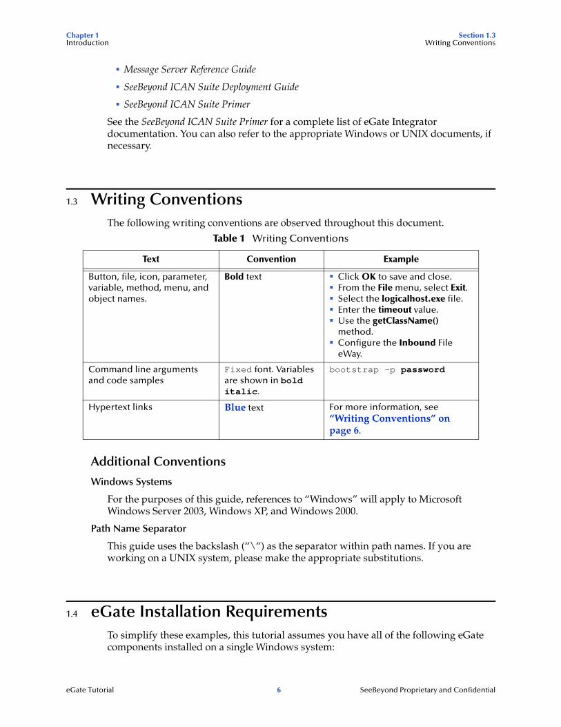
1.3 Writing ConventionsThe following writing conventions are observed throughout this document.
Additional Conventions
Windows Systems
For the purposes of this guide, references to “Windows” will apply to Microsoft Windows Server 2003, Windows XP, and Windows 2000.
Path Name Separator
This guide uses the backslash (“\“) as the separator within path names. If you are working on a UNIX system, please make the appropriate substitutions.
1.4 eGate Installation RequirementsTo simplify these examples, this tutorial assumes you have all of the following eGate components installed on a single Windows system:
Table 1 Writing Conventions
Text Convention Example
Button, file, icon, parameter, variable, method, menu, and object names.
Bold text ! Click OK to save and close.! From the File menu, select Exit.! Select the logicalhost.exe file.! Enter the timeout value.! Use the getClassName()
method.! Configure the Inbound File
eWay.
Command line arguments and code samples
Fixed font. Variables are shown in bold italic.
bootstrap -p password
Hypertext links Blue text For more information, see “Writing Conventions” on page 6.
eGate Tutorial 6 SeeBeyond Proprietary and Confidential
Chapter 1 Section 1.5Introduction The SeeBeyond Web Site
! eGate Repository
! Logical Host
! Enterprise Designer
! eGate product
! FileeWay product
Refer to the eGate Integrator Installation Guide for system requirements and installation instructions.
1.5 The SeeBeyond Web SiteThe SeeBeyond Web site is your best source for up-to-the-minute product news and technical support information. The site’s URL is:
http://www.seebeyond.com
eGate Tutorial 7 SeeBeyond Proprietary and Confidential
Chapter 2
Features of the Enterprise Designer
The Enterprise Designer is the graphical user interface (GUI) used to design and implement ICAN 5.0 projects. This chapter overviews the features and interface of the Enterprise Designer window.
This chapter includes
! “Enterprise Designer Components” on page 8
! “Menu Bar” on page 9
! “Enterprise Explorer” on page 10
! “Project Editor” on page 10
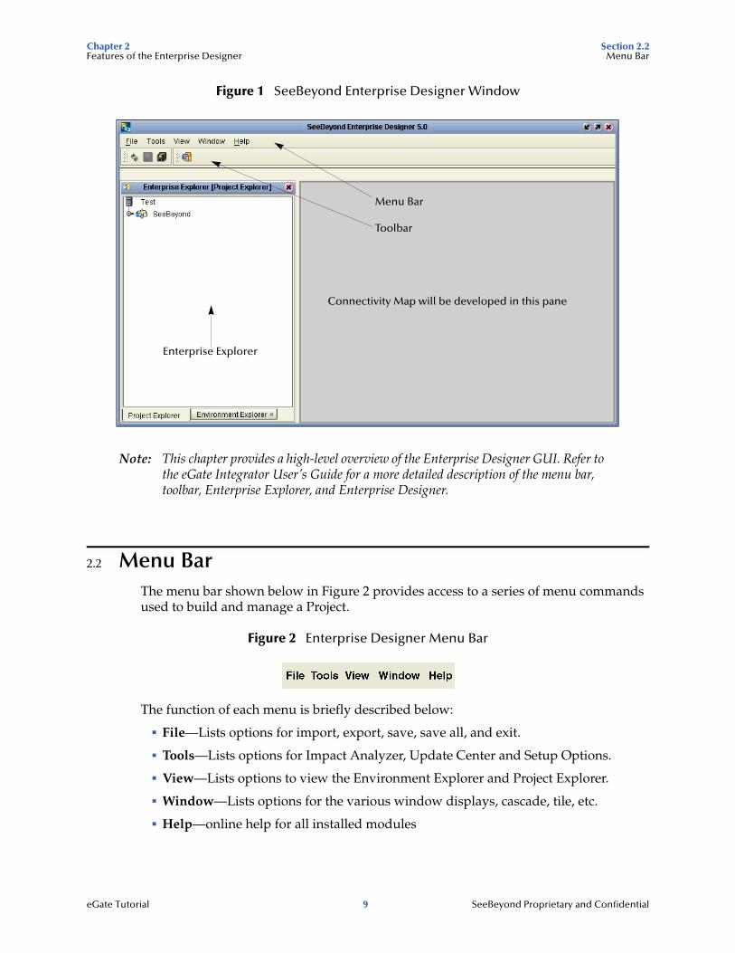
2.1 Enterprise Designer ComponentsThe Enterprise Designer is used to create and configure the components of an eGate Project. Each component of this interface is identified in Figure 1.
eGate Tutorial 8 SeeBeyond Proprietary and Confidential
Chapter 2 Section 2.2Features of the Enterprise Designer Menu Bar
Figure 1 SeeBeyond Enterprise Designer Window
Note: This chapter provides a high-level overview of the Enterprise Designer GUI. Refer to the eGate Integrator User’s Guide for a more detailed description of the menu bar, toolbar, Enterprise Explorer, and Enterprise Designer.
2.2 Menu BarThe menu bar shown below in Figure 2 provides access to a series of menu commands used to build and manage a Project.
Figure 2 Enterprise Designer Menu Bar
The function of each menu is briefly described below:
! File—Lists options for import, export, save, save all, and exit.
! Tools—Lists options for Impact Analyzer, Update Center and Setup Options.
! View—Lists options to view the Environment Explorer and Project Explorer.
! Window—Lists options for the various window displays, cascade, tile, etc.
! Help—online help for all installed modules
Enterprise Explorer
Menu Bar
Toolbar
Connectivity Map will be developed in this pane
eGate Tutorial 9 SeeBeyond Proprietary and Confidential
Chapter 2 Section 2.3Features of the Enterprise Designer Enterprise Explorer
2.3 Enterprise ExplorerThe Enterprise Explorer organizes all of the components of a Project into a series of folders and contains the following two tabs:
! Project Explorer—Logical configurations designed to help solve a business problem. This branch includes all the components of an Enterprise Designer Project, including Connectivity Maps, Services, Object Type Definitions (OTD), and Deployment Profiles.
! Environment Explorer—Collections of logical hosts and external systems capable of hosting eGate components and information about external systems, which may be involved with an eGate configuration.
2.4 Project EditorThe Project Editor contains the “nuts-and-bolts” of a Project. This part of the Enterprise Designer is empty when you start a new Project. However, as you work through the tutorial, the Project Editor will quickly fill with components and graphical structures representing the various stages of the Project. The types of windows in the Project Editor area include:
! Connectivity Map—Contains business logic components, such as Services, Topics, queues, and eWays, that you include in the structure of a Project.
! Java Collaboration Editor—Contains the business rules defined in Java.
! XSLT Collaboration Editor—Contains the business rules defined in XSLT.
! OTD Editor—Edits and tests the OTDs (Object Type Definitions)
! Deployment Profile Editor—Edits the deployment profile
! Environment—Collection of physical resources (logical hosts and external systems)
eGate Tutorial 10 SeeBeyond Proprietary and Confidential
Chapter 3
Building a Simple Project
This tutorial provides step-by-step procedures for creating and testing an eGate Project with Java Collaboration rules. This Project addresses a business challenge in which a company uses two systems to handle time tracking and payroll distribution. As the systems use different formats, one system must use data from the other system to accomplish its tasks. This chapter explains how to structure your Project to allow the two systems to work together effectively.
This chapter includes
! “Business Challenge” on page 11
! “Project Overview” on page 12
! “Create the Sample Data” on page 15
! “Create a New Project” on page 16
! “Create a Connectivity Map” on page 18
! “Add Components to the Connectivity Map” on page 19
! “Create a New Object Type Definition” on page 21
! “Configure the Services” on page 26
! “Apply the Collaborations” on page 46
! “Link Components in the Connectivity Map” on page 47
! “Configure the eWays and JMS Connections” on page 49
! “Create Environment and Activate the Deployment Profile” on page 52
! “Run the Bootstrap and Management Agent” on page 57
! “Verify the Output Data” on page 58
3.1 Business ChallengeThe Project described in this chapter provides a solution to the following business challenge:
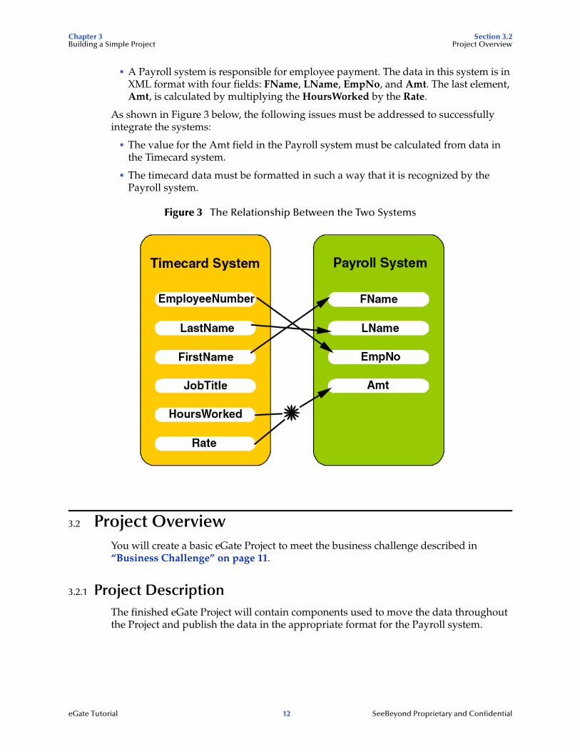
! A timecard system tracks the weekly hours worked by employees. The data in this system is in XML format with six fields: EmployeeNumber, LastName, FirstName, JobTitle, HoursWorked, and Rate.
eGate Tutorial 11 SeeBeyond Proprietary and Confidential
Chapter 3 Section 3.2Building a Simple Project Project Overview
! A Payroll system is responsible for employee payment. The data in this system is in XML format with four fields: FName, LName, EmpNo, and Amt. The last element, Amt, is calculated by multiplying the HoursWorked by the Rate.
As shown in Figure 3 below, the following issues must be addressed to successfully integrate the systems:
! The value for the Amt field in the Payroll system must be calculated from data in the Timecard system.
! The timecard data must be formatted in such a way that it is recognized by the Payroll system.
Figure 3 The Relationship Between the Two Systems
3.2 Project OverviewYou will create a basic eGate Project to meet the business challenge described in “Business Challenge” on page 11.
3.2.1 Project DescriptionThe finished eGate Project will contain components used to move the data throughout the Project and publish the data in the appropriate format for the Payroll system.
eGate Tutorial 12 SeeBeyond Proprietary and Confidential
Chapter 3 Section 3.2Building a Simple Project Project Overview
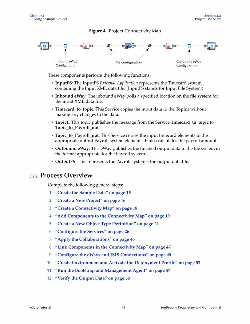
Figure 4 Project Connectivity Map
These components perform the following functions:
! InputFS: The InputFS External Application represents the Timecard system containing the Input XML data file. (InputFS stands for Input File System.)
! Inbound eWay: The inbound eWay polls a specified location on the file system for the input XML data file.
! Timecard_to_topic: This Service copies the input data to the Topic1 without making any changes to the data.
! Topic1: This topic publishes the message from the Service Timecard_to_topic to Topic_to_Payroll_out.
! Topic_to_Payroll_out: This Service copies the input timecard elements to the appropriate output Payroll system elements. It also calculates the payroll amount.
! Outbound eWay: This eWay publishes the finished output data to the file system in the format appropriate for the Payroll system.
! OutputFS: This represents the Payroll system—the output data file.
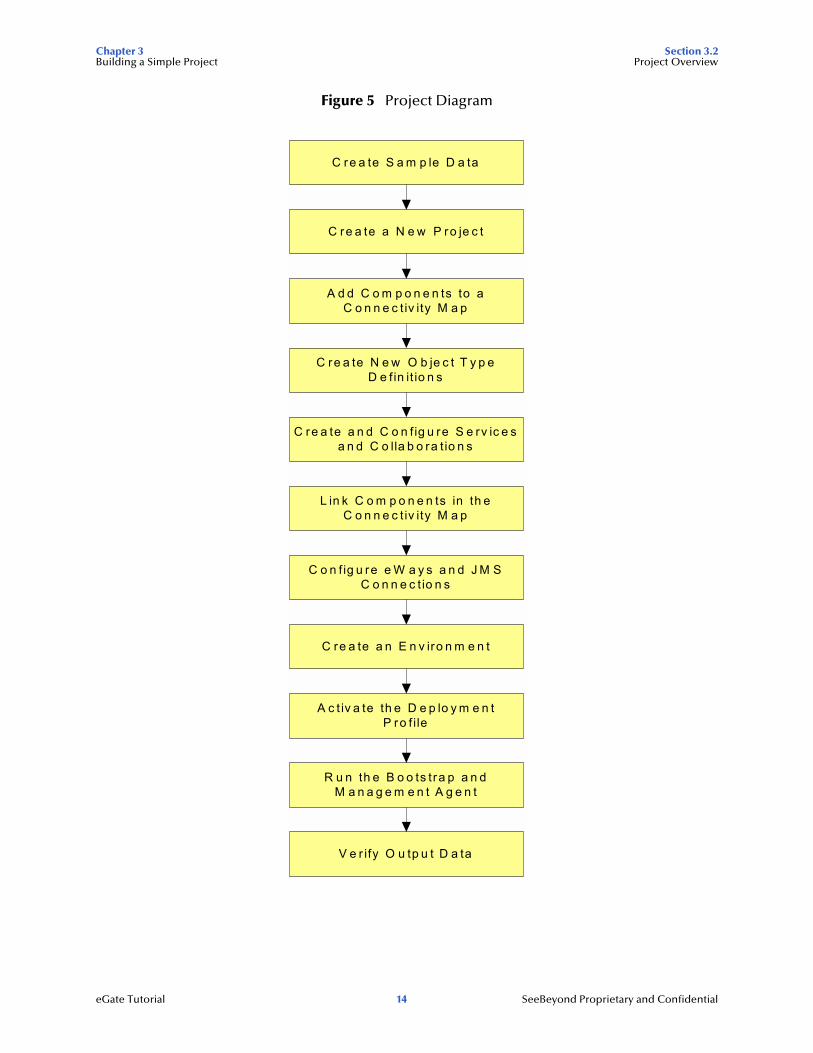
3.2.2 Process OverviewComplete the following general steps:
1 “Create the Sample Data” on page 15
2 “Create a New Project” on page 16
3 “Create a Connectivity Map” on page 18
4 “Add Components to the Connectivity Map” on page 19
5 “Create a New Object Type Definition” on page 21
6 “Configure the Services” on page 26
7 “Apply the Collaborations” on page 46
8 “Link Components in the Connectivity Map” on page 47
9 “Configure the eWays and JMS Connections” on page 49
10 “Create Environment and Activate the Deployment Profile” on page 52
11 “Run the Bootstrap and Management Agent” on page 57
12 “Verify the Output Data” on page 58
Inbound eWay Configuration
Outbound eWay Configuration
JMS configuration
eGate Tutorial 13 SeeBeyond Proprietary and Confidential
Chapter 3 Section 3.2Building a Simple Project Project Overview
Figure 5 Project Diagram
C re a te S a m p le D a ta
C re a te a N e w P ro je c t
A d d C o m p o n e n ts to aC o n n e c t iv ity M a p
C re a te N e w O b je c t T y p eD e fin it io n s
C re a te a n d C o n f ig u re S e rv ic e sa n d C o lla b o ra t io n s
L in k C o m p o n e n ts in th eC o n n e c t iv ity M a p
C o n fig u re e W a y s a n d J M SC o n n e c t io n s
C re a te a n E n v iro n m e n t
A c t iv a te th e D e p lo y m e n tP ro f ile
R u n th e B o o ts tra p a n dM a n a g e m e n t A g e n t
V e r ify O u tp u t D a ta
eGate Tutorial 14 SeeBeyond Proprietary and Confidential
Chapter 3 Section 3.3Building a Simple Project Create the Sample Data
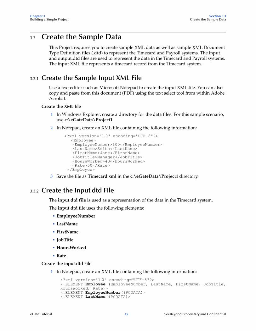
3.3 Create the Sample DataThis Project requires you to create sample XML data as well as sample XML Document Type Definition files (.dtd) to represent the Timecard and Payroll systems. The input and output.dtd files are used to represent the data in the Timecard and Payroll systems. The input XML file represents a timecard record from the Timecard system.
3.3.1 Create the Sample Input XML FileUse a text editor such as Microsoft Notepad to create the input XML file. You can also copy and paste from this document (PDF) using the text select tool from within Adobe Acrobat.
Create the XML file
1 In Windows Explorer, create a directory for the data files. For this sample scenario, use c:\eGateData\Project1.
2 In Notepad, create an XML file containing the following information:
<?xml version="1.0" encoding="UTF-8"?> <Employee> <EmployeeNumber>100</EmployeeNumber> <LastName>Smith</LastName> <FirstName>Jane</FirstName> <JobTitle>Manager</JobTitle> <HoursWorked>40</HoursWorked> <Rate>50</Rate>
</Employee>
3 Save the file as Timecard.xml in the c:\eGateData\Project1 directory.
3.3.2 Create the Input.dtd FileThe input.dtd file is used as a representation of the data in the Timecard system.
The input.dtd file uses the following elements:
! EmployeeNumber
! LastName
! FirstName
! JobTitle
! HoursWorked
! Rate
Create the input.dtd File
1 In Notepad, create an XML file containing the following information:
<?xml version="1.0" encoding="UTF-8"?><!ELEMENT Employee (EmployeeNumber, LastName, FirstName, JobTitle,HoursWorked, Rate)><!ELEMENT EmployeeNumber(#PCDATA)><!ELEMENT LastName(#PCDATA)>
eGate Tutorial 15 SeeBeyond Proprietary and Confidential

Chapter 3 Section 3.4Building a Simple Project Create a New Project
<!ELEMENT FirstName(#PCDATA)><!ELEMENT JobTitle(#PCDATA)><!ELEMENT HoursWorked(#PCDATA)><!ELEMENT Rate(#PCDATA)>
2 Save the file as input.dtd in the c:\eGateData\Project1 directory.
3.3.3 Create the Output.dtd FileThe output.dtd file is used as a representation of the data in the Payroll system.
The output.dtd file uses the following elements:
! FName
! LName
! EmpNo
! Amt
Create the output.dtd file
1 In Notepad, create an XML file containing the following information:
<?xml version="1.0" encoding="UTF-8"?><!ELEMENT Employee (FName, LName, EmpNo, Amt)><!ELEMENT FName(#PCDATA)><!ELEMENT LName(#PCDATA)><!ELEMENT EmpNo(#PCDATA)><!ELEMENT Amt(#PCDATA)>
2 Save the file as output.dtd in the c:\eGateData\Project1 directory.
3.4 Create a New ProjectThere are many ways to create a Project and link the modules. This tutorial presents one scenario. Begin by creating and naming a Project in the Enterprise Designer.
Start the Enterprise Designer
1 Start the Enterprise Designer by executing runed.bat in your ican50 folder (c:\ican50\edesigner\bin).
The Enterprise Designer Login dialog box appears.
eGate Tutorial 16 SeeBeyond Proprietary and Confidential
Chapter 3 Section 3.4Building a Simple Project Create a New Project
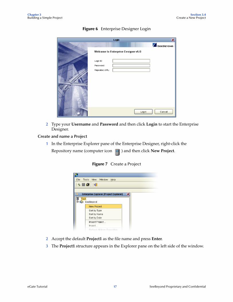
Figure 6 Enterprise Designer Login
2 Type your Username and Password and then click Login to start the Enterprise Designer.
Create and name a Project
1 In the Enterprise Explorer pane of the Enterprise Designer, right-click the
Repository name (computer icon ) and then click New Project.
Figure 7 Create a Project
2 Accept the default Project1 as the file name and press Enter.
3 The Project1 structure appears in the Explorer pane on the left side of the window.
eGate Tutorial 17 SeeBeyond Proprietary and Confidential
Chapter 3 Section 3.5Building a Simple Project Create a Connectivity Map
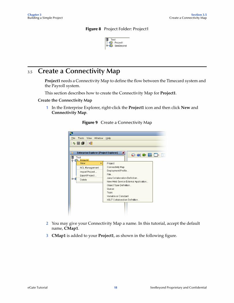
Figure 8 Project Folder: Project1
3.5 Create a Connectivity MapProject1 needs a Connectivity Map to define the flow between the Timecard system and the Payroll system.
This section describes how to create the Connectivity Map for Project1.
Create the Connectivity Map
1 In the Enterprise Explorer, right-click the Project1 icon and then click New and Connectivity Map.
Figure 9 Create a Connectivity Map
2 You may give your Connectivity Map a name. In this tutorial, accept the default name, CMap1.
3 CMap1 is added to your Project1, as shown in the following figure.
eGate Tutorial 18 SeeBeyond Proprietary and Confidential

Chapter 3 Section 3.6Building a Simple Project Add Components to the Connectivity Map
Figure 10 Project1 with a Connectivity Map (CMap1)
Note: The CMap1 Connectivity Map appears as an icon in the Project Explorer. A CMap1 tab is also added at the bottom of the Connectivity Map.
3.6 Add Components to the Connectivity MapIn this section, you will add the components to the Connectivity Map and link the components as shown in Figure 4 on page 13.
3.6.1 Add Components to the Connectivity MapIn this section, you will add the following components to the Connectivity Map:
! InputFS (File External Application)
! Timecard_to_topic
! Topic1
! Topic_to_Payroll_out
! OutputFS (File External Application)
Create the InputFS
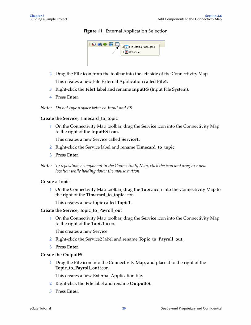
1 On the Connectivity Map toolbar, click the External Application arrow (shown in Figure 11) to display the list and then click File External Application.
This adds a new File icon to the toolbar.
External Application
Queue
TopicService
Collapse or expandProject node
Web Services Client
eGate Tutorial 19 SeeBeyond Proprietary and Confidential
Chapter 3 Section 3.6Building a Simple Project Add Components to the Connectivity Map
Figure 11 External Application Selection
2 Drag the File icon from the toolbar into the left side of the Connectivity Map.
This creates a new File External Application called File1.
3 Right-click the File1 label and rename InputFS (Input File System).
4 Press Enter.
Note: Do not type a space between Input and FS.
Create the Service, Timecard_to_topic
1 On the Connectivity Map toolbar, drag the Service icon into the Connectivity Map to the right of the InputFS icon.
This creates a new Service called Service1.
2 Right-click the Service label and rename Timecard_to_topic.
3 Press Enter.
Note: To reposition a component in the Connectivity Map, click the icon and drag to a new location while holding down the mouse button.
Create a Topic
1 On the Connectivity Map toolbar, drag the Topic icon into the Connectivity Map to the right of the Timecard_to_topic icon.
This creates a new topic called Topic1.
Create the Service, Topic_to_Payroll_out
1 On the Connectivity Map toolbar, drag the Service icon into the Connectivity Map to the right of the Topic1 icon.
This creates a new Service.
2 Right-click the Service2 label and rename Topic_to_Payroll_out.
3 Press Enter.
Create the OutputFS
1 Drag the File icon into the Connectivity Map, and place it to the right of the Topic_to_Payroll_out icon.
This creates a new External Application file.
2 Right-click the File label and rename OutputFS.
3 Press Enter.
eGate Tutorial 20 SeeBeyond Proprietary and Confidential
Chapter 3 Section 3.7Building a Simple Project Create a New Object Type Definition
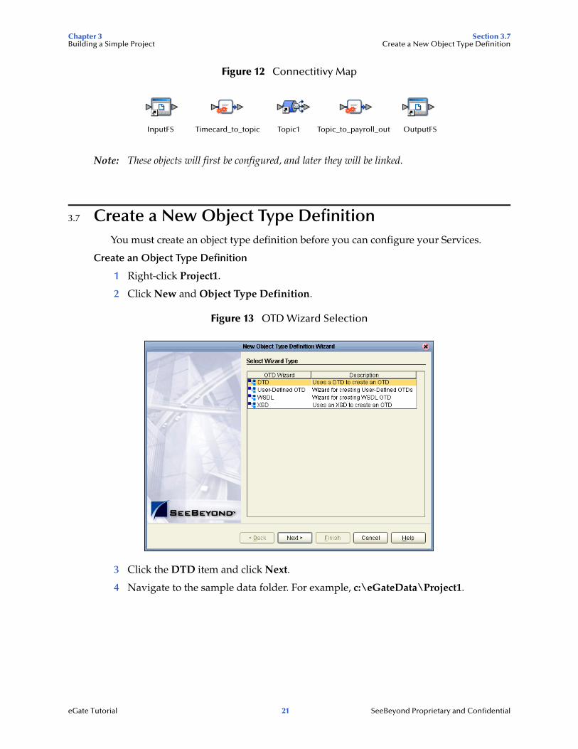
Figure 12 Connectitivy Map
Note: These objects will first be configured, and later they will be linked.
3.7 Create a New Object Type DefinitionYou must create an object type definition before you can configure your Services.
Create an Object Type Definition
1 Right-click Project1.
2 Click New and Object Type Definition.
Figure 13 OTD Wizard Selection
3 Click the DTD item and click Next.
4 Navigate to the sample data folder. For example, c:\eGateData\Project1.
InputFS Timecard_to_topic Topic1 Topic_to_payroll_out OutputFS
eGate Tutorial 21 SeeBeyond Proprietary and Confidential

Chapter 3 Section 3.7Building a Simple Project Create a New Object Type Definition
Figure 14 Select DTD Files
5 Highlight input.dtd and click Select (or double-click).
6 Highlight output.dtd and click Select (or double-click).
The input.dtd and output.dtd should appear in the Selected DTDs.
(You can also select both at the same time by holding down the shift key.)
7 When both input.dtd and output.dtd appear in the Selected DTDs, click Next.
Note: The Up one Level icon (number 1 in Figure 14 above) is used to navigate to a previous screen; this is useful if you’ve made an incorrect selection.
1
eGate Tutorial 22 SeeBeyond Proprietary and Confidential
Chapter 3 Section 3.7Building a Simple Project Create a New Object Type Definition
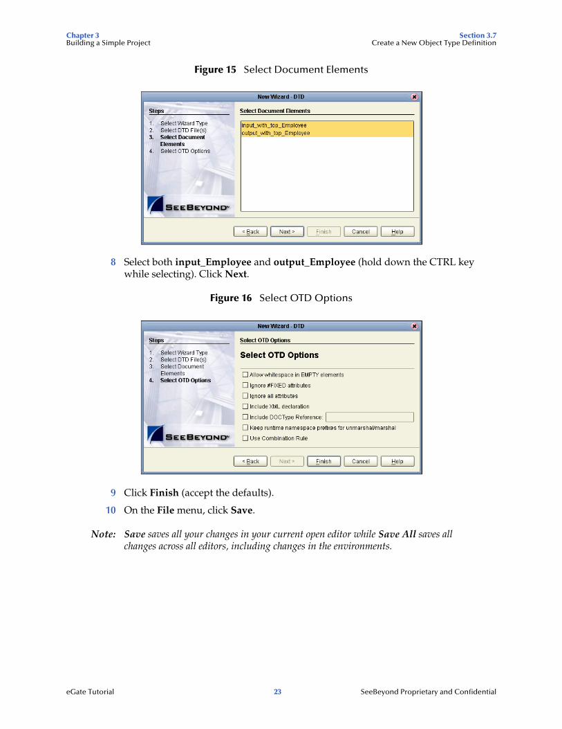
Figure 15 Select Document Elements
8 Select both input_Employee and output_Employee (hold down the CTRL key while selecting). Click Next.
Figure 16 Select OTD Options
9 Click Finish (accept the defaults).
10 On the File menu, click Save.
Note: Save saves all your changes in your current open editor while Save All saves all changes across all editors, including changes in the environments.
eGate Tutorial 23 SeeBeyond Proprietary and Confidential
Chapter 3 Section 3.7Building a Simple Project Create a New Object Type Definition
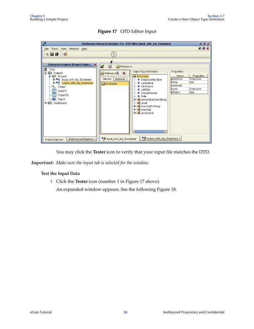
Figure 17 OTD Editor Input
You may click the Tester icon to verify that your input file matches the DTD.
Important: Make sure the input tab is selected for the window.
Test the Input Data
1 Click the Tester icon (number 1 in Figure 17 above).
An expanded window appears. See the following Figure 18.
1
eGate Tutorial 24 SeeBeyond Proprietary and Confidential
Chapter 3 Section 3.7Building a Simple Project Create a New Object Type Definition
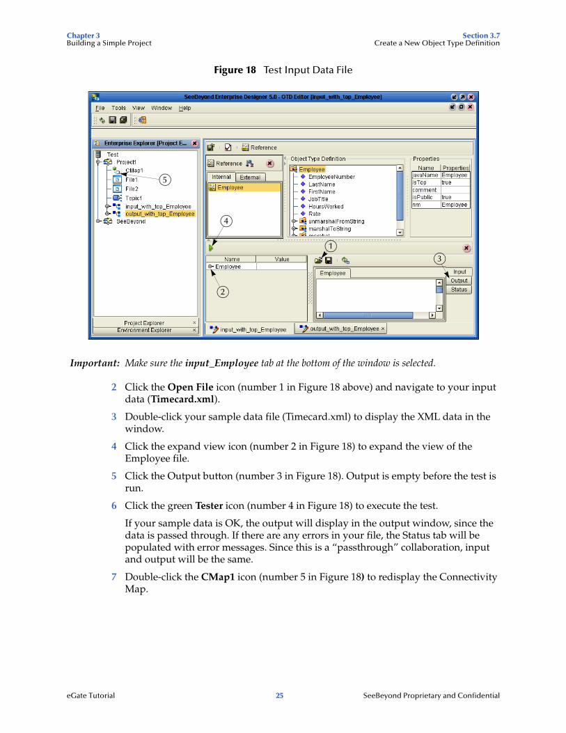
Figure 18 Test Input Data File
Important: Make sure the input_Employee tab at the bottom of the window is selected.
2 Click the Open File icon (number 1 in Figure 18 above) and navigate to your input data (Timecard.xml).
3 Double-click your sample data file (Timecard.xml) to display the XML data in the window.
4 Click the expand view icon (number 2 in Figure 18) to expand the view of the Employee file.
5 Click the Output button (number 3 in Figure 18). Output is empty before the test is run.
6 Click the green Tester icon (number 4 in Figure 18) to execute the test.
If your sample data is OK, the output will display in the output window, since the data is passed through. If there are any errors in your file, the Status tab will be populated with error messages. Since this is a “passthrough” collaboration, input and output will be the same.
7 Double-click the CMap1 icon (number 5 in Figure 18) to redisplay the Connectivity Map.
5
4
3
1
2
eGate Tutorial 25 SeeBeyond Proprietary and Confidential
Chapter 3 Section 3.8Building a Simple Project Configure the Services
3.8 Configure the ServicesYou will use Service wizards in the following steps to configure your Collaborations.
3.8.1 Configure Timecard_to_topicSelect Web Service Interface
1 Right-click Project1.
2 Click New and Java Collaboration Definition.
The Java Collaboration Definition Wizard appears.
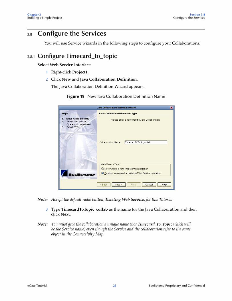
Figure 19 New Java Collaboration Definition Name
Note: Accept the default radio button, Existing Web Service, for this Tutorial.
3 Type TimecardToTopic_collab as the name for the Java Collaboration and then click Next.
Note: You must give the collaboration a unique name (not Timecard_to_topic which will be the Service name) even though the Service and the collaboration refer to the same object in the Connectivity Map.
eGate Tutorial 26 SeeBeyond Proprietary and Confidential
Chapter 3 Section 3.8Building a Simple Project Configure the Services
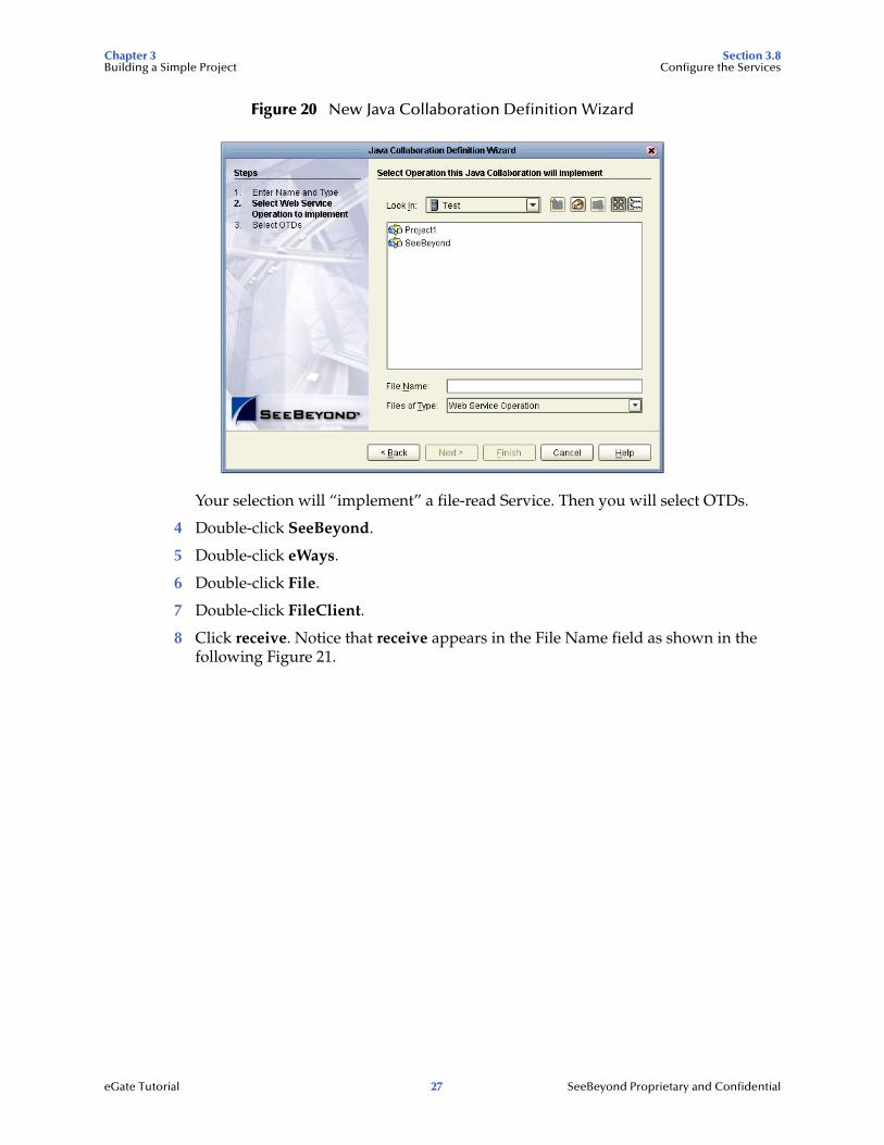
Figure 20 New Java Collaboration Definition Wizard
Your selection will “implement” a file-read Service. Then you will select OTDs.
4 Double-click SeeBeyond.
5 Double-click eWays.
6 Double-click File.
7 Double-click FileClient.
8 Click receive. Notice that receive appears in the File Name field as shown in the following Figure 21.
eGate Tutorial 27 SeeBeyond Proprietary and Confidential
Chapter 3 Section 3.8Building a Simple Project Configure the Services
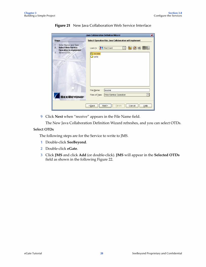
Figure 21 New Java Collaboration Web Service Interface
9 Click Next when “receive” appears in the File Name field.
The New Java Collaboration Definition Wizard refreshes, and you can select OTDs.
Select OTDs
The following steps are for the Service to write to JMS.
1 Double-click SeeBeyond.
2 Double-click eGate.
3 Click JMS and click Add (or double-click). JMS will appear in the Selected OTDs field as shown in the following Figure 22.
eGate Tutorial 28 SeeBeyond Proprietary and Confidential
Chapter 3 Section 3.8Building a Simple Project Configure the Services
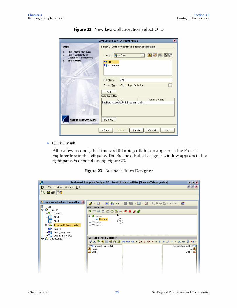
Figure 22 New Java Collaboration Select OTD
4 Click Finish.
After a few seconds, the TimecardToTopic_collab icon appears in the Project Explorer tree in the left pane. The Business Rules Designer window appears in the right pane. See the following Figure 23.
Figure 23 Business Rules Designer
1
eGate Tutorial 29 SeeBeyond Proprietary and Confidential
Chapter 3 Section 3.8Building a Simple Project Configure the Services
3.8.2 Apply Business Rules for TimecardToTopic_collabIn TimecardToTopic_collab you will connect the input from the Timecard to the JMS OTD.
Configure Input (Timecard) with Business Rules Designer
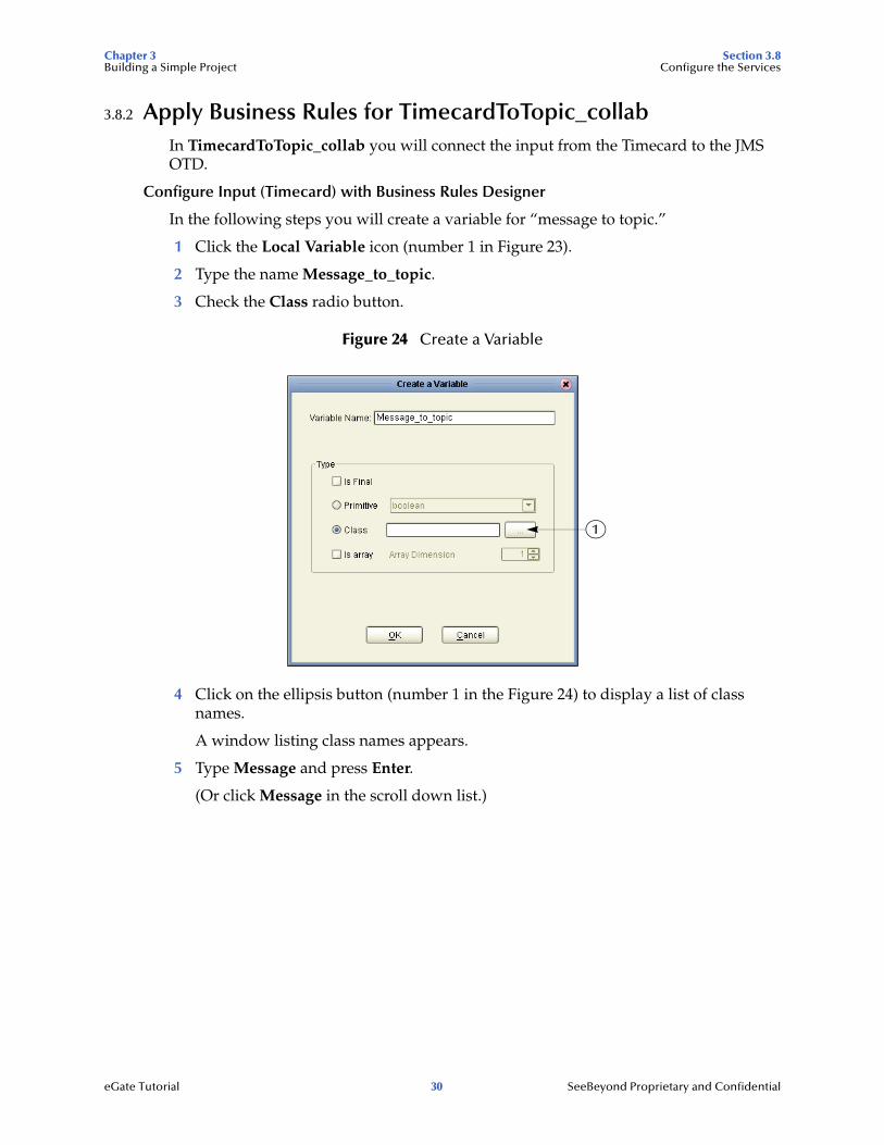
In the following steps you will create a variable for “message to topic.”
1 Click the Local Variable icon (number 1 in Figure 23).
2 Type the name Message_to_topic.
3 Check the Class radio button.
Figure 24 Create a Variable
4 Click on the ellipsis button (number 1 in the Figure 24) to display a list of class names.
A window listing class names appears.
5 Type Message and press Enter.
(Or click Message in the scroll down list.)
1
eGate Tutorial 30 SeeBeyond Proprietary and Confidential

Chapter 3 Section 3.8Building a Simple Project Configure the Services
Figure 25 Class Names
6 Click OK when “Message” is highlighted.
The class message name will appear in the Class field of the Create a Variable window.
7 Click OK to accept the name (com.stc.connectors.jms.Message) and close the Create a Variable window.
Initialize the variable
1 Right-click JMS_1 in the left pane and click Select a method to call.
2 Click createMessage() from the list.
The createMessage box appears in the center pane of the Business Rules Designer.
eGate Tutorial 31 SeeBeyond Proprietary and Confidential

Chapter 3 Section 3.8Building a Simple Project Configure the Services
Figure 26 Create Message
3 Connect result (Message) from the box to Message_to_topic in the right pane (as shown in Figure 26 above).
Note: Click slightly inside the box.
The variable is now initialized and you can start mapping.
Map and Send the Text Message
1 Double-click Input in the left pane of the Business Rules Designer window to expand the view.
2 Double-click Message_to_topic in the right pane to expand the view.
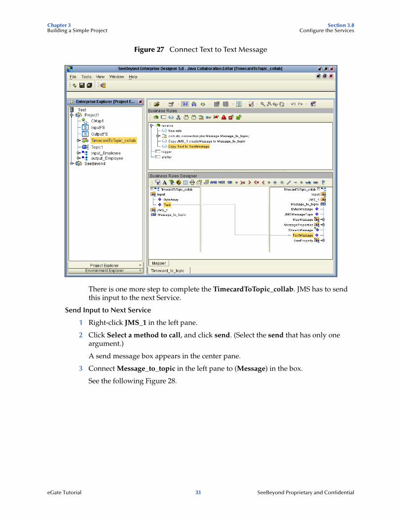
3 Connect Text in the left pane to TextMessage in the right pane.
eGate Tutorial 32 SeeBeyond Proprietary and Confidential
Chapter 3 Section 3.8Building a Simple Project Configure the Services
Figure 27 Connect Text to Text Message
There is one more step to complete the TimecardToTopic_collab. JMS has to send this input to the next Service.
Send Input to Next Service
1 Right-click JMS_1 in the left pane.
2 Click Select a method to call, and click send. (Select the send that has only one argument.)
A send message box appears in the center pane.
3 Connect Message_to_topic in the left pane to (Message) in the box.
See the following Figure 28.
eGate Tutorial 33 SeeBeyond Proprietary and Confidential

Chapter 3 Section 3.8Building a Simple Project Configure the Services
Figure 28 Send Method Box
Note: Notice that the objects in Figure 27 and Figure 28 reside in both the right and left pane of the Business Rules Designer window. Keep in mind that the GUIs (JMS_1 for example) refer to the same object.
Note: The business rules appear in the top pane. To redisplay a graphical representation of a business rule, click that business rule.
4 On the File menu, click Save All.
5 Click the Window menu, and click Close All.
6 Double-click CMap1 to redisplay the Connectivity Map.
This completes the setup for the TimecardToTopic_collab collaboration definition. You are now ready to drag-and-drop the Service configuration into your Collaboration Map, but first you will configure Topic_to_Payroll_out.
3.8.3 Configure Topic_to_Payroll_outSelect a Web Service Operation
First you will configure your Web Service interface.
1 Right-click Project1.
2 Click New and Java Collaboration Definition.
eGate Tutorial 34 SeeBeyond Proprietary and Confidential

Chapter 3 Section 3.8Building a Simple Project Configure the Services
Figure 29 New Java Collaboration Definition Editor
Note: Accept the default radio button Existing Web Service for this Tutorial.
3 Type TopicToPayrollOut_collab as the name for the Java Collaboration Definition and then click Next.
4 From the New Java Collaboration Definition Wizard, double-click SeeBeyond.
5 Double-click eGate.
6 Double-click JMS. This is your source for this Collaboration.
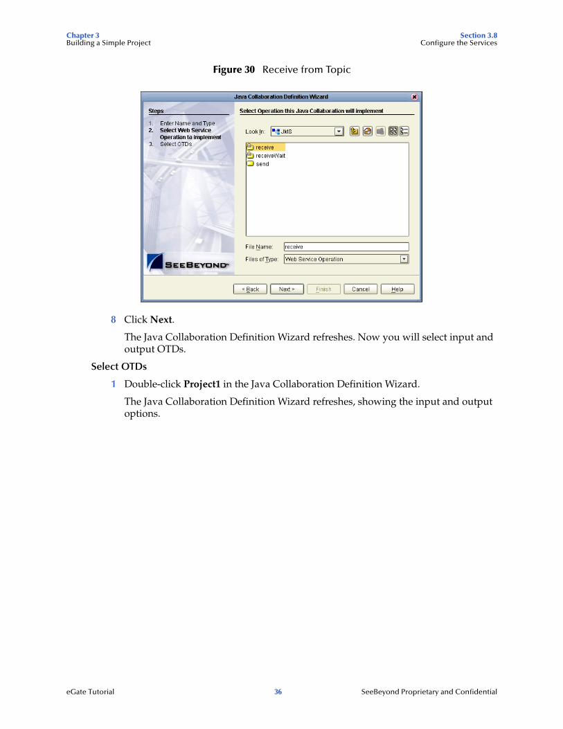
7 Click receive. (receive is a method/Web Service used to read a message from a topic that your collaboration will implement.)
eGate Tutorial 35 SeeBeyond Proprietary and Confidential
Chapter 3 Section 3.8Building a Simple Project Configure the Services
Figure 30 Receive from Topic
8 Click Next.
The Java Collaboration Definition Wizard refreshes. Now you will select input and output OTDs.
Select OTDs
1 Double-click Project1 in the Java Collaboration Definition Wizard.
The Java Collaboration Definition Wizard refreshes, showing the input and output options.
eGate Tutorial 36 SeeBeyond Proprietary and Confidential

Chapter 3 Section 3.8Building a Simple Project Configure the Services
Figure 31 Input/Output OTDs for TopicToPayrollOut_collab
2 Double-click input_Employee and then double-click output_Employee to move these selections to the list of Selected OTDs.
Before clicking Finish, you must first select FileClient which represents your output to an external file.
3 Click the drop-down arrow icon for the Look In list.
Figure 32 Drop Down Arrow button
4 Click SeeBeyond.
5 Double-click eWays.
6 Double-click File.
7 Double-click FileClient.
Notice that the FileClient_1 has been added to the list of Selected OTDs. See the following Figure 33.
eGate Tutorial 37 SeeBeyond Proprietary and Confidential
Chapter 3 Section 3.8Building a Simple Project Configure the Services
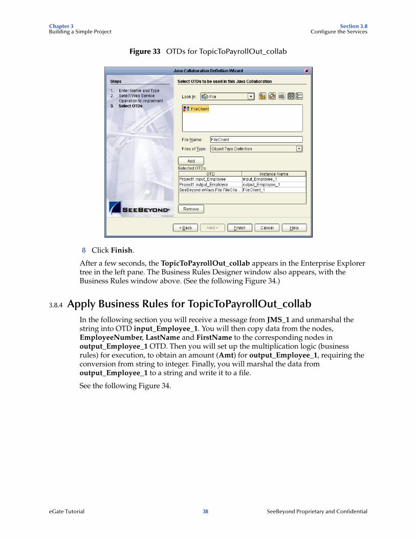
Figure 33 OTDs for TopicToPayrollOut_collab
8 Click Finish.
After a few seconds, the TopicToPayrollOut_collab appears in the Enterprise Explorer tree in the left pane. The Business Rules Designer window also appears, with the Business Rules window above. (See the following Figure 34.)
3.8.4 Apply Business Rules for TopicToPayrollOut_collab In the following section you will receive a message from JMS_1 and unmarshal the string into OTD input_Employee_1. You will then copy data from the nodes, EmployeeNumber, LastName and FirstName to the corresponding nodes in output_Employee_1 OTD. Then you will set up the multiplication logic (business rules) for execution, to obtain an amount (Amt) for output_Employee_1, requiring the conversion from string to integer. Finally, you will marshal the data from output_Employee_1 to a string and write it to a file.
See the following Figure 34.
eGate Tutorial 38 SeeBeyond Proprietary and Confidential
Chapter 3 Section 3.8Building a Simple Project Configure the Services
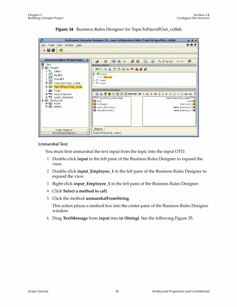
Figure 34 Business Rules Designer for TopicToPayrollOut_collab
Unmarshal Text
You must first unmarshal the text input from the topic into the input OTD.
1 Double-click input in the left pane of the Business Rules Designer to expand the view.
2 Double-click input_Employee_1 in the left pane of the Business Rules Designer to expand the view.
3 Right-click input_Employee_1 in the left pane of the Business Rules Designer.
4 Click Select a method to call.
5 Click the method unmarshalFromString.
This action places a method box into the center pane of the Business Rules Designer window.
6 Drag TextMessage from input into in (String). See the following Figure 35.
eGate Tutorial 39 SeeBeyond Proprietary and Confidential

Chapter 3 Section 3.8Building a Simple Project Configure the Services
Figure 35 Java Collaboration Editor - Unmarshal From String
Connect Input and Output OTD Nodes
Make sure the views of input_Employee_1 in the left pane and output_Employee_1 in the right pane of the Business Rules Designer are expanded.
1 Double-click output_Employee_1 in the right pane to expand the view.
2 Connect the nodes between the input_Employee_1 OTD in the left pane with the output_Employee_1 OTD in the right pane of the Business Rules Designer:
Note: When you begin to connect the nodes, the previous display will disappear but the record of your action appears in the Business Rules pane which is just above the Business Rules Designer pane.
Connect the following nodes:
Connect EmployeeNumber to EmpNo.
Connect LastName to LName.
Connect FirstName to FName.
eGate Tutorial 40 SeeBeyond Proprietary and Confidential

Chapter 3 Section 3.8Building a Simple Project Configure the Services
Figure 36 Connect Input/Output OTD Nodes
Prepare for the Multiplication Operation
1 Click the Call Java Method icon to display a method box.
The method box will appear in your center pane. See the following Figure 37.
2 Type Integer (be sure to use capital I) into the Class Name box and click Search.
3 Scroll down and click parseInt(java.lang.String s) from the methods list and click OK.
eGate Tutorial 41 SeeBeyond Proprietary and Confidential

Chapter 3 Section 3.8Building a Simple Project Configure the Services
Figure 37 Integer Java Method
4 Repeat the previous steps because you will need two method boxes.
Notice that as you drag methods to your workspace, the boxes will overlap. Be sure to locate these boxes and drag them to a proper location. See the positioning of the boxes in Figure 39.
Place these two boxes on the left side of the workspace in the center pane.
5 Click the Multiplication Operator on the toolbar and drag the method box to the right of the two parsing boxes.
The Multiplication Method box appears.
Note: You can adjust the size of the window panes by clicking on the frame and adjusting. Refer to the following Figure 38.
Figure 38 Window Adjust
eGate Tutorial 42 SeeBeyond Proprietary and Confidential

Chapter 3 Section 3.8Building a Simple Project Configure the Services
Use Methods to Prepare the Data for String to Integer Conversion
Figure 39 Prepare for Multiplication
1 Click the Call New Constructor icon.
2 Type Integer (be sure to use capital I) and press Enter.
3 Click java.lang.Integer(int value) in the list and click OK.
A new method box appears. Place this method box under, or to the right of the Multiplication Method box. This method is necessary to convert the int primitive to an Integer Object.
4 Click the Call Java Method icon once more to display a method box.
5 Type Integer (if not already displayed) and click toString() in the list.
6 Click OK. (Place this method to the right and slightly above the java.lang.Integer.)
This method will convert the Integer Object to a String.
Connect the Nodes
1 Connect HoursWorked in the input_Employee_1 OTD to s(string) in the first Integer.parseInt method box.
2 Connect Rate in the input_Employee_1 OTD to s(string) in the second Integer.parseInt method box.
The numbers are now set for conversion to int and ready for multiplication as integers.
3 Connect HoursWorked from result to number1 in the Multiplication method box.
4 Connect Rate from result to number2 in the Multiplication method box.
5 Connect result from the multiplication to value(int) in the java.lang.Integer.
6 Connect the result(integer) to Integer in the toString method box.
7 Connect the result(String) to Amt in output_Employee_1 in the right pane.
This completes the multiplication. See the following Figure 40.
eGate Tutorial 43 SeeBeyond Proprietary and Confidential
Chapter 3 Section 3.8Building a Simple Project Configure the Services
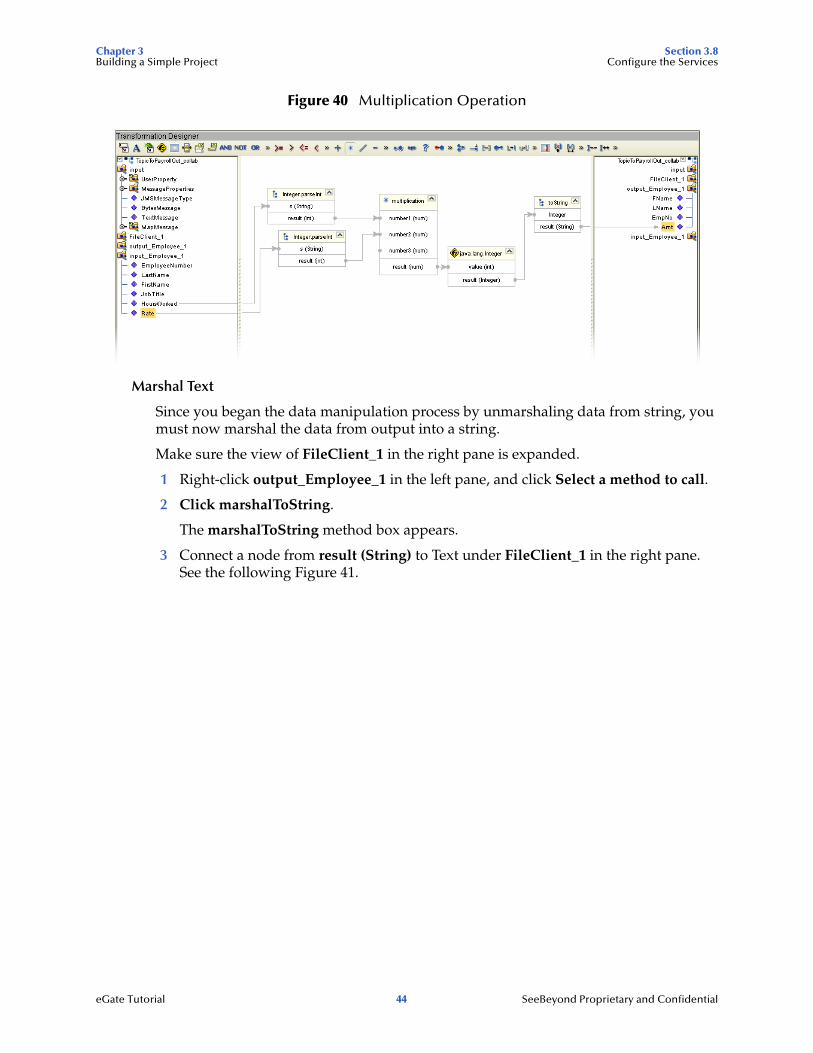
Figure 40 Multiplication Operation
Marshal Text
Since you began the data manipulation process by unmarshaling data from string, you must now marshal the data from output into a string.
Make sure the view of FileClient_1 in the right pane is expanded.
1 Right-click output_Employee_1 in the left pane, and click Select a method to call.
2 Click marshalToString.
The marshalToString method box appears.
3 Connect a node from result (String) to Text under FileClient_1 in the right pane. See the following Figure 41.
eGate Tutorial 44 SeeBeyond Proprietary and Confidential
Chapter 3 Section 3.8Building a Simple Project Configure the Services
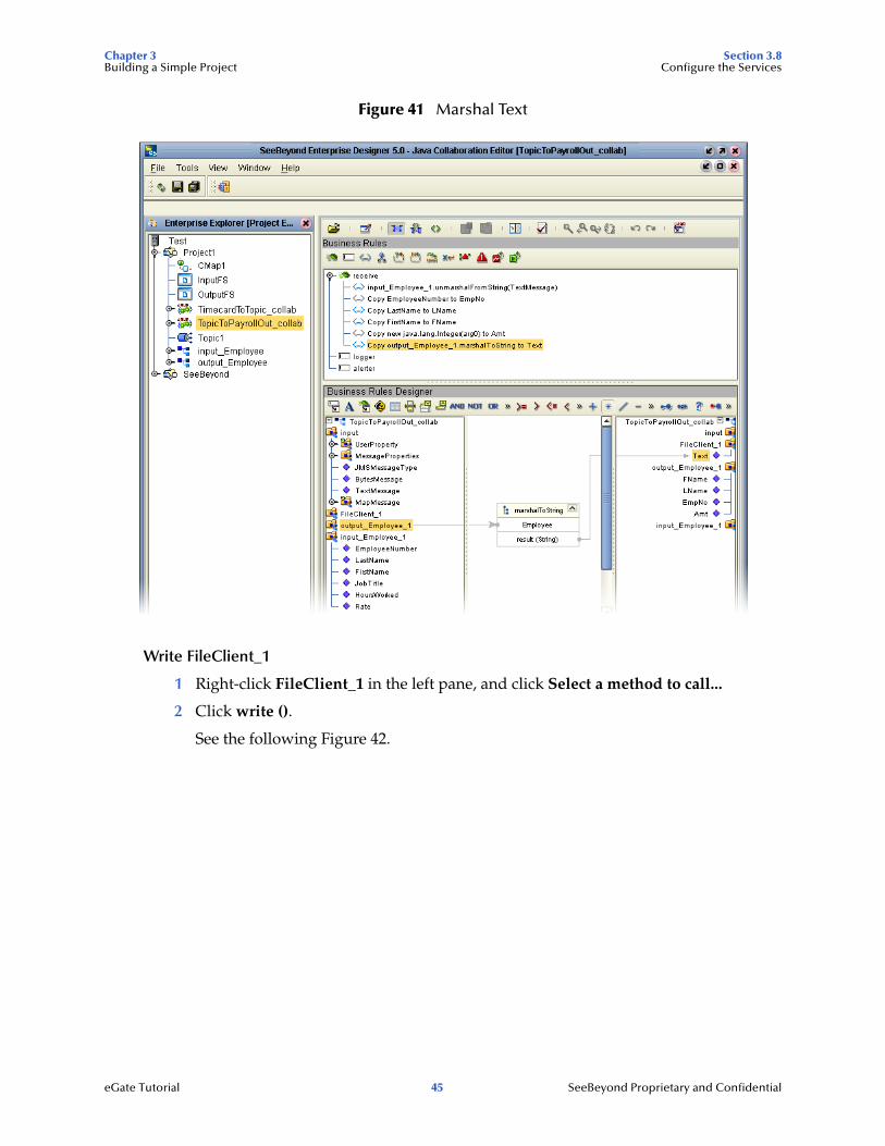
Figure 41 Marshal Text
Write FileClient_1
1 Right-click FileClient_1 in the left pane, and click Select a method to call...
2 Click write ().
See the following Figure 42.
eGate Tutorial 45 SeeBeyond Proprietary and Confidential

Chapter 3 Section 3.9Building a Simple Project Apply the Collaborations
Figure 42 Write File Application
A write method box appears with an arrow pointing to FileApplication. This instructs the system to write to the output file.
3 On the File menu, click Save All.
This completes TopicToPayrollOut_collab using the Business Rules Designer window.
You will use the drag-and-drop technique to move the configurations into your Services.
4 Navigate back to the Connectivity Map if it is not already displayed. You can close the current window or you can double-click the Connectivity Map name, CMap1.
3.9 Apply the CollaborationsYou have configured your Collaboration Definitions (business rules) in the previous sections. You are now ready to associate your Collaboration Definitions with Services using a simple drag-and-drop technique.
eGate Tutorial 46 SeeBeyond Proprietary and Confidential
Chapter 3 Section 3.9Building a Simple Project Apply the Collaborations
Drag-and-drop TimecardToTopic_collab
Refer to Figure 44 for the following steps.
1 Double-click your Connectivity Map icon to return to the Connectivity Map.
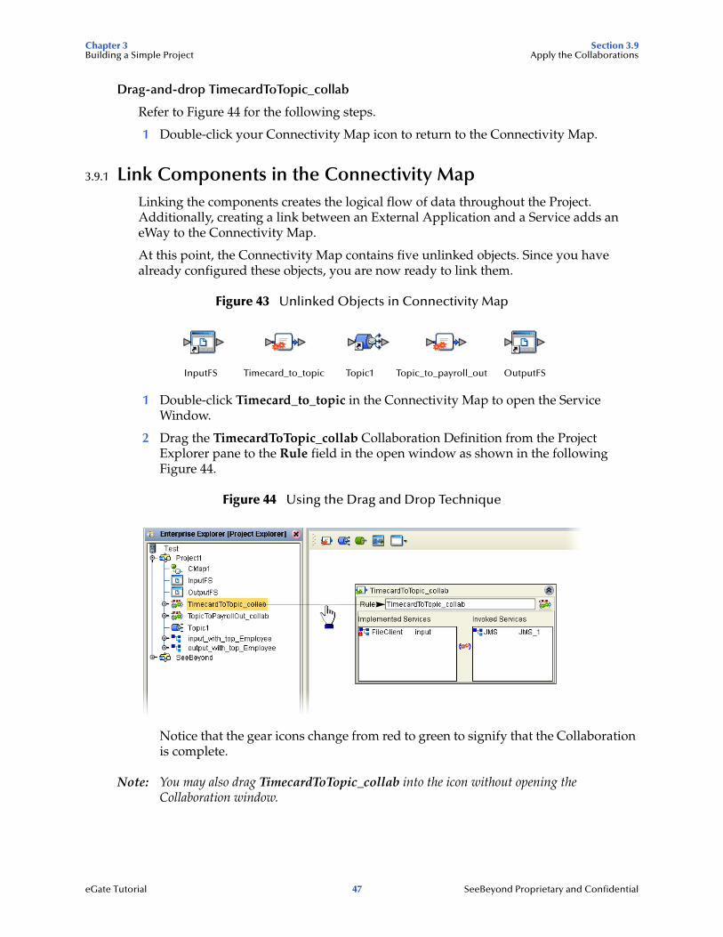
3.9.1 Link Components in the Connectivity MapLinking the components creates the logical flow of data throughout the Project. Additionally, creating a link between an External Application and a Service adds an eWay to the Connectivity Map.
At this point, the Connectivity Map contains five unlinked objects. Since you have already configured these objects, you are now ready to link them.
Figure 43 Unlinked Objects in Connectivity Map
1 Double-click Timecard_to_topic in the Connectivity Map to open the Service Window.
2 Drag the TimecardToTopic_collab Collaboration Definition from the Project Explorer pane to the Rule field in the open window as shown in the following Figure 44.
Figure 44 Using the Drag and Drop Technique
Notice that the gear icons change from red to green to signify that the Collaboration is complete.
Note: You may also drag TimecardToTopic_collab into the icon without opening the Collaboration window.
InputFS Timecard_to_topic Topic1 Topic_to_payroll_out OutputFS
eGate Tutorial 47 SeeBeyond Proprietary and Confidential

Chapter 3 Section 3.9Building a Simple Project Apply the Collaborations
Figure 45 Connect Input to Client
3 Connect the InputFS to FileClient.
Figure 46 Connect JMS to Topic
4 Connect JMS_1 to Topic1.
5 Click the close button to close the binding box.
Figure 47 Timecard_to_topic Linked
Drag-and-drop TopicToPayrollOut_collab
1 Double-click Topic_to_Payroll_out in the Connectivity Map to open the Service Window.
2 Drag the TopicToPayrollOut_collab Collaboration Definition from the Project Explorer pane to the Rule field in the open window.
InputFS Timecard_to_topic Topic1 Topic_to_payroll_out OutputFS
eGate Tutorial 48 SeeBeyond Proprietary and Confidential
Chapter 3 Section 3.10Building a Simple Project Configure the eWays and JMS Connections
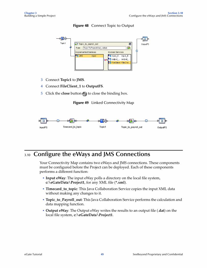
Figure 48 Connect Topic to Output
3 Connect Topic1 to JMS.
4 Connect FileClient_1 to OutputFS.
5 Click the close button to close the binding box.
Figure 49 Linked Connectivity Map
3.10 Configure the eWays and JMS ConnectionsYour Connectivity Map contains two eWays and JMS connections. These components must be configured before the Project can be deployed. Each of these components performs a different function:
! Input eWay: The input eWay polls a directory on the local file system, c:\eGateData\Project1, for any XML file (*.xml).
! Timecard_to_topic: This Java Collaboration Service copies the input XML data without making any changes to it.
! Topic_to_Payroll_out: This Java Collaboration Service performs the calculation and data mapping function.
! Output eWay: The Output eWay writes the results to an output file (.dat) on the local file system, c:\eGateData\Project1.
eGate Tutorial 49 SeeBeyond Proprietary and Confidential

Chapter 3 Section 3.10Building a Simple Project Configure the eWays and JMS Connections
Configure the Inbound eWay
Figure 50 Inbound eWay
1 Double-click the first eWay and then click Inbound File eWay from the drop-down list, click OK.
Figure 51 External Type Dialog Box
This creates a new inbound eWay and the Properties Dialog Box appears.
Figure 52 Properties Configuration (Inbound eWay)
Refer to the arrows in the previous Figure 52. These are the fields you will modify.
2 Click once on the current path to select and type a correct directory path. In this tutorial the path is c:\eGateData\Project1 (number 1 in Figure 52 above).
3 Click once on the current Input File Name field and enter *.xml. The eWay will read any files with the .xml extension (number 2 in Figure 52 above.)
4 Click OK to close the Properties Dialog Box for the inbound eWay.
InputFS Timecard_to_topic
21
eGate Tutorial 50 SeeBeyond Proprietary and Confidential

Chapter 3 Section 3.10Building a Simple Project Configure the eWays and JMS Connections
Note: If the Polling interval value is left unchanged, the eWay polls the directory location every five seconds (5000 milliseconds).
Configure the Outbound eWay
Figure 53 Outbound eWay
1 Double-click the second eWay and then click Outbound File eWay, click OK.
Use the same path you used for the inbound eWay (c:\eGateData\Project1). Accept the default output file name: Output%d.dat.
2 Click OK to close the Properties Dialog Box for the outbound eWay.
Figure 54 Properties Configuration (Outbound eWay)
Note: The Multiple records per file setting determines whether records will be concatenated in a file. A True setting means that multiple records will be written in the same file. A False setting, as shown in Figure 54 above, means that only one record will be written to one file and the file numbers (outputN.data where N is incremented) will increment with each reload of the input file.
You have now configured both the input and output eWays.
JMS Client Configuration
The JMS Client Configuration icons appear on both sides of the Topic1 icon.
Topic_to_payroll_out OuptutFS
eGate Tutorial 51 SeeBeyond Proprietary and Confidential
Chapter 3 Section 3.11Building a Simple Project Create Environment and Activate the Deployment Profile
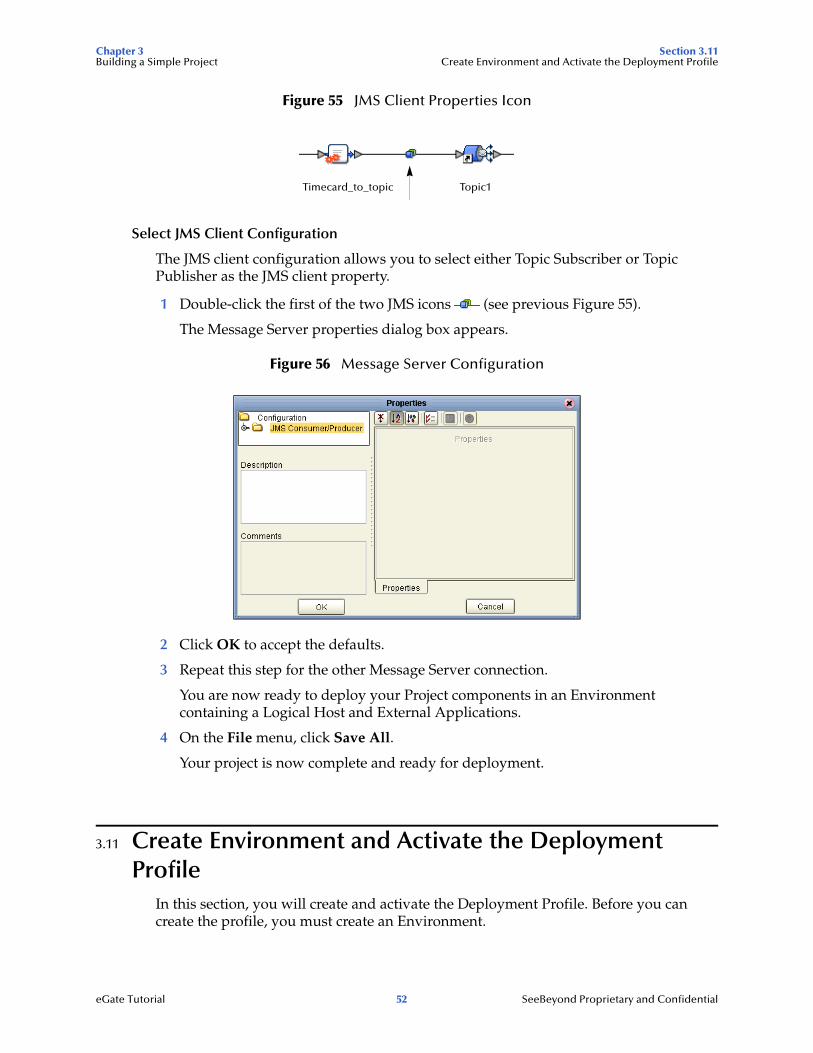
Figure 55 JMS Client Properties Icon
Select JMS Client Configuration
The JMS client configuration allows you to select either Topic Subscriber or Topic Publisher as the JMS client property.
1 Double-click the first of the two JMS icons (see previous Figure 55).
The Message Server properties dialog box appears.
Figure 56 Message Server Configuration
2 Click OK to accept the defaults.
3 Repeat this step for the other Message Server connection.
You are now ready to deploy your Project components in an Environment containing a Logical Host and External Applications.
4 On the File menu, click Save All.
Your project is now complete and ready for deployment.
3.11 Create Environment and Activate the Deployment Profile
In this section, you will create and activate the Deployment Profile. Before you can create the profile, you must create an Environment.
Timecard_to_topic Topic1
eGate Tutorial 52 SeeBeyond Proprietary and Confidential

Chapter 3 Section 3.11Building a Simple Project Create Environment and Activate the Deployment Profile
Create an Environment and Logical Host
An Environment is a collection of physical resources and their configurations that are used to host Project components. An Environment contains logical hosts and external systems.
1 Click View from the Menu bar and click Environment Explorer.
2 Right-click the Repository name ( ) and click New Environment.
3 Right-click Environment1 and rename Tutorial1. Press Enter.
4 Right-click Tutorial1, and click New Logical Host.
5 Accept the default name LogicalHost1.
This creates a LogicalHost1 window in the right pane.
Create an Integration Server
1 Right-click LogicalHost1 in the Enterprise Explorer window, and then click New SeeBeyond Integration Server.
IntegrationSvr1 will appear in the LogicalHost1 window.
Create a Message Server
1 Right-click LogicalHost1 in the Enterprise Explorer window and then click New SeeBeyond JMS IQ Manager.
2 SBJmsIQMgr1 will appear in the LogicalHost1 window.
Figure 57 Create Logical Host Servers
These servers automatically appear in the LogicalHost1 dialog box.
Create an External File System for Inbound eWay
1 Right-click Tutorial1, and then click New File External System.
eGate Tutorial 53 SeeBeyond Proprietary and Confidential

Chapter 3 Section 3.11Building a Simple Project Create Environment and Activate the Deployment Profile
Figure 58 External File Inbound
2 Type Timecard_in in the name field.
3 Select Inbound File eWay and click OK.
This places the inbound external system, Timecard_in in the Environment Editor pane.
Create an External File System for Outbound eWay
1 Right-click Tutorial1, and then click New File External System.
Figure 59 External File Outbound
2 Type Payroll_out in the name field.
3 Select Outbound File eWay and click OK.
This places the outbound external system, Payroll_out in the Environment Editor pane.
3.11.1 Create a New Deployment ProfileBefore you can map components, you must first create a Deployment Profile.
Create a New Deployment Profile
A Deployment Profile contains information about how Project components will be deployed in an Environment, and it also maps components to the Environment.
1 Click the Project Explorer tab to return to the Project Explorer pane of your Project.
2 Right-click Project1, and then click New and Deployment Profile.
3 Accept the default name Deployment1 and click OK.
eGate Tutorial 54 SeeBeyond Proprietary and Confidential
Chapter 3 Section 3.11Building a Simple Project Create Environment and Activate the Deployment Profile
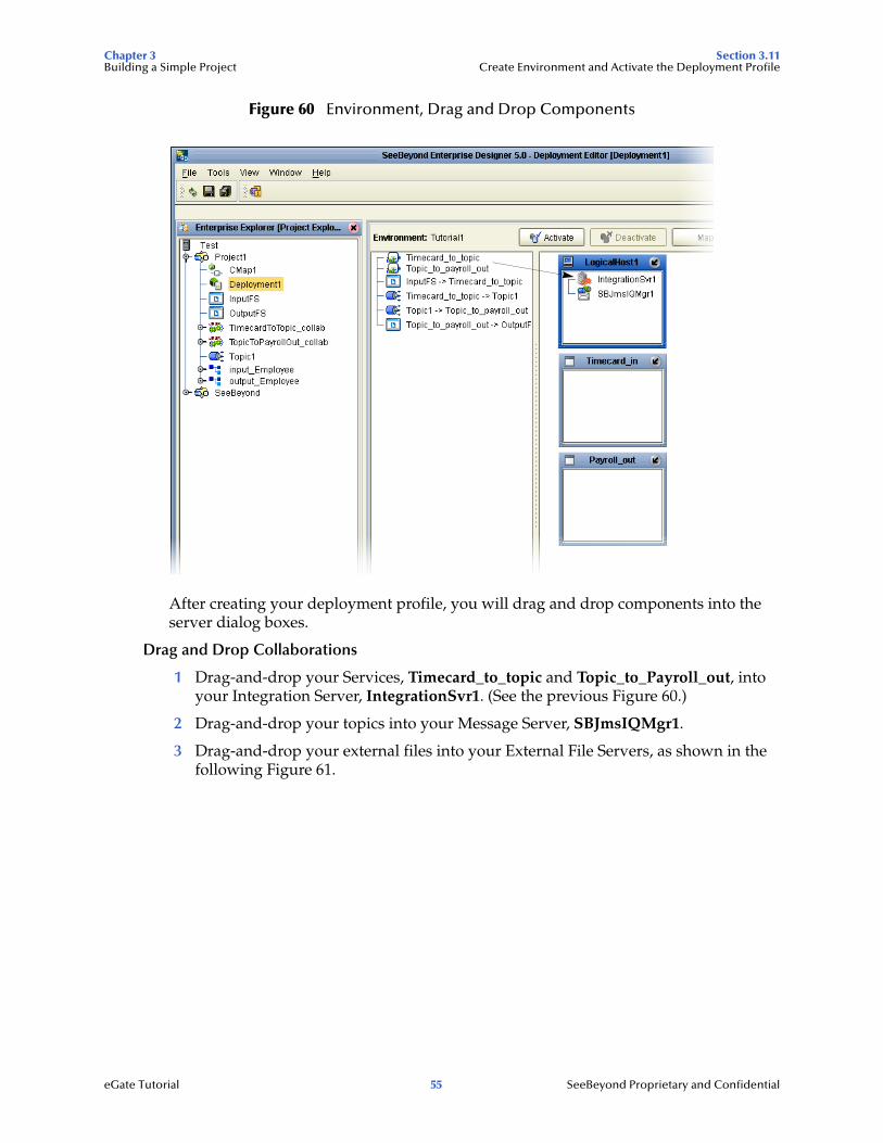
Figure 60 Environment, Drag and Drop Components
After creating your deployment profile, you will drag and drop components into the server dialog boxes.
Drag and Drop Collaborations
1 Drag-and-drop your Services, Timecard_to_topic and Topic_to_Payroll_out, into your Integration Server, IntegrationSvr1. (See the previous Figure 60.)
2 Drag-and-drop your topics into your Message Server, SBJmsIQMgr1.
3 Drag-and-drop your external files into your External File Servers, as shown in the following Figure 61.
eGate Tutorial 55 SeeBeyond Proprietary and Confidential
Chapter 3 Section 3.11Building a Simple Project Create Environment and Activate the Deployment Profile
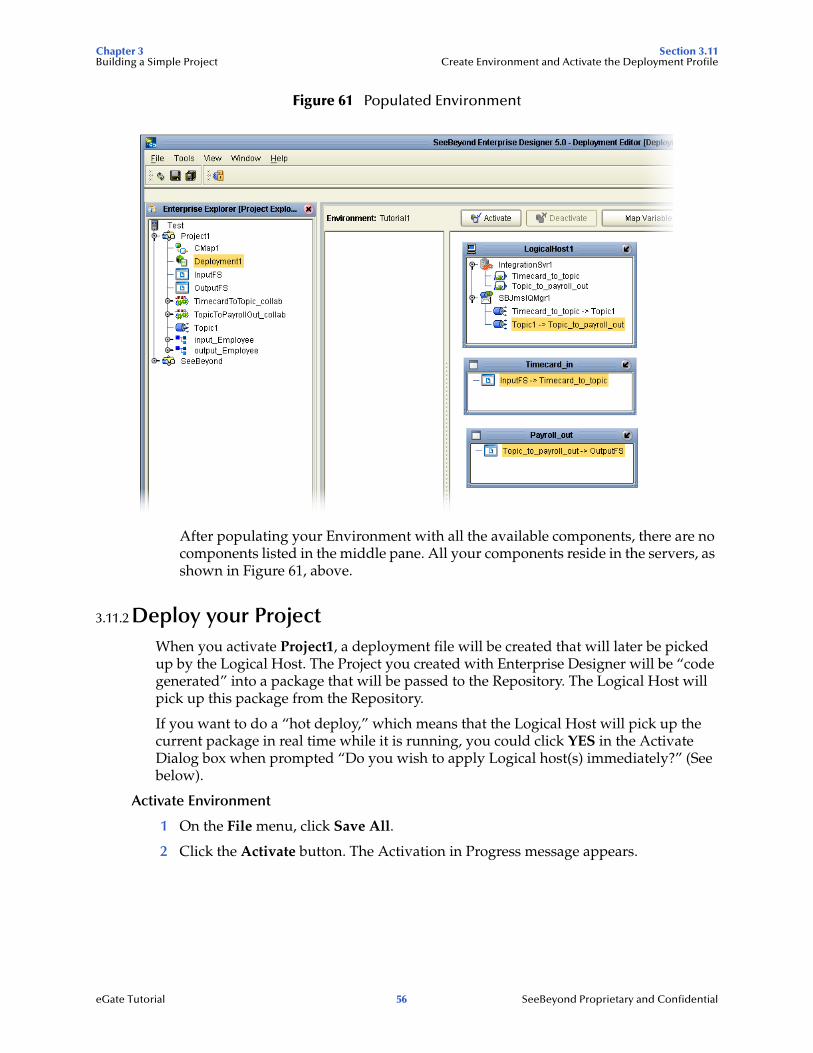
Figure 61 Populated Environment
After populating your Environment with all the available components, there are no components listed in the middle pane. All your components reside in the servers, as shown in Figure 61, above.
3.11.2 Deploy your ProjectWhen you activate Project1, a deployment file will be created that will later be picked up by the Logical Host. The Project you created with Enterprise Designer will be “code generated” into a package that will be passed to the Repository. The Logical Host will pick up this package from the Repository.
If you want to do a “hot deploy,” which means that the Logical Host will pick up the current package in real time while it is running, you could click YES in the Activate Dialog box when prompted “Do you wish to apply Logical host(s) immediately?” (See below).
Activate Environment
1 On the File menu, click Save All.
2 Click the Activate button. The Activation in Progress message appears.
eGate Tutorial 56 SeeBeyond Proprietary and Confidential
Chapter 3 Section 3.12Building a Simple Project Run the Bootstrap and Management Agent
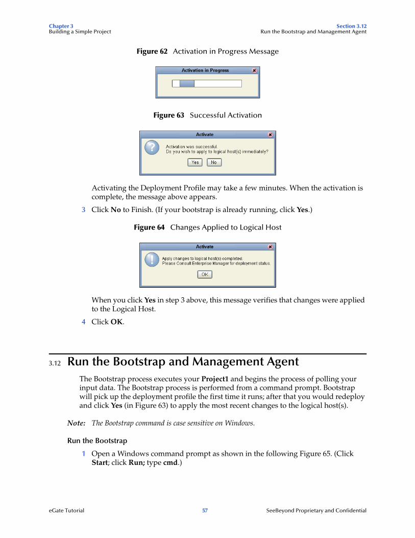
Figure 62 Activation in Progress Message
Figure 63 Successful Activation
Activating the Deployment Profile may take a few minutes. When the activation is complete, the message above appears.
3 Click No to Finish. (If your bootstrap is already running, click Yes.)
Figure 64 Changes Applied to Logical Host
When you click Yes in step 3 above, this message verifies that changes were applied to the Logical Host.
4 Click OK.
3.12 Run the Bootstrap and Management AgentThe Bootstrap process executes your Project1 and begins the process of polling your input data. The Bootstrap process is performed from a command prompt. Bootstrap will pick up the deployment profile the first time it runs; after that you would redeploy and click Yes (in Figure 63) to apply the most recent changes to the logical host(s).
Note: The Bootstrap command is case sensitive on Windows.
Run the Bootstrap
1 Open a Windows command prompt as shown in the following Figure 65. (Click Start; click Run; type cmd.)
eGate Tutorial 57 SeeBeyond Proprietary and Confidential
Chapter 3 Section 3.13Building a Simple Project Verify the Output Data
2 Navigate to where you installed the logicalhost; for example, ican50\logicalhost\bootstrap\bin. Then type the following command:
CD \ican50\logicalhost\bootstrap\bin
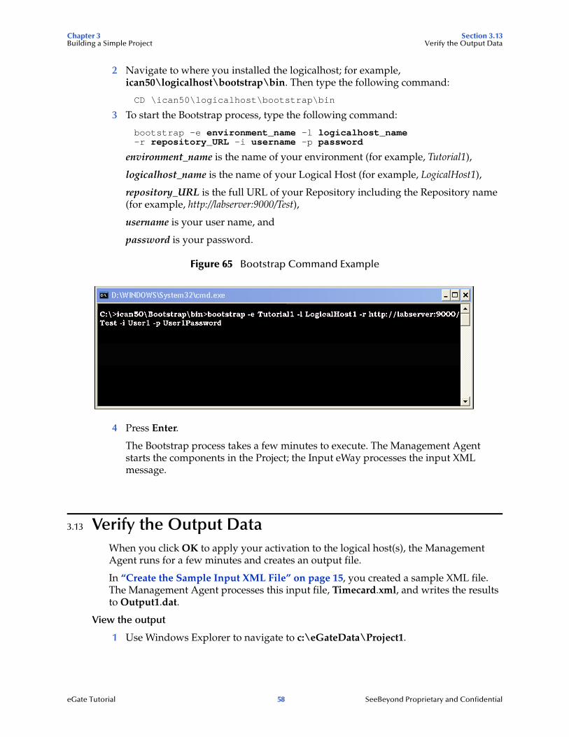
3 To start the Bootstrap process, type the following command:
bootstrap -e environment_name -l logicalhost_name -r repository_URL -i username -p password
environment_name is the name of your environment (for example, Tutorial1),
logicalhost_name is the name of your Logical Host (for example, LogicalHost1),
repository_URL is the full URL of your Repository including the Repository name (for example, http://labserver:9000/Test),
username is your user name, and
password is your password.
Figure 65 Bootstrap Command Example
4 Press Enter.
The Bootstrap process takes a few minutes to execute. The Management Agent starts the components in the Project; the Input eWay processes the input XML message.
3.13 Verify the Output DataWhen you click OK to apply your activation to the logical host(s), the Management Agent runs for a few minutes and creates an output file.
In “Create the Sample Input XML File” on page 15, you created a sample XML file. The Management Agent processes this input file, Timecard.xml, and writes the results to Output1.dat.
View the output
1 Use Windows Explorer to navigate to c:\eGateData\Project1.
eGate Tutorial 58 SeeBeyond Proprietary and Confidential
Chapter 3 Section 3.14Building a Simple Project Enterprise Manager Overview
2 See that the Input eWay, after processing the input file, renamed the input file to Timecard.~in.
3 See that the Output eWay generated the output file, Output1.dat.
4 Use Windows Wordpad or a similar text edit application to view the contents of the output file.
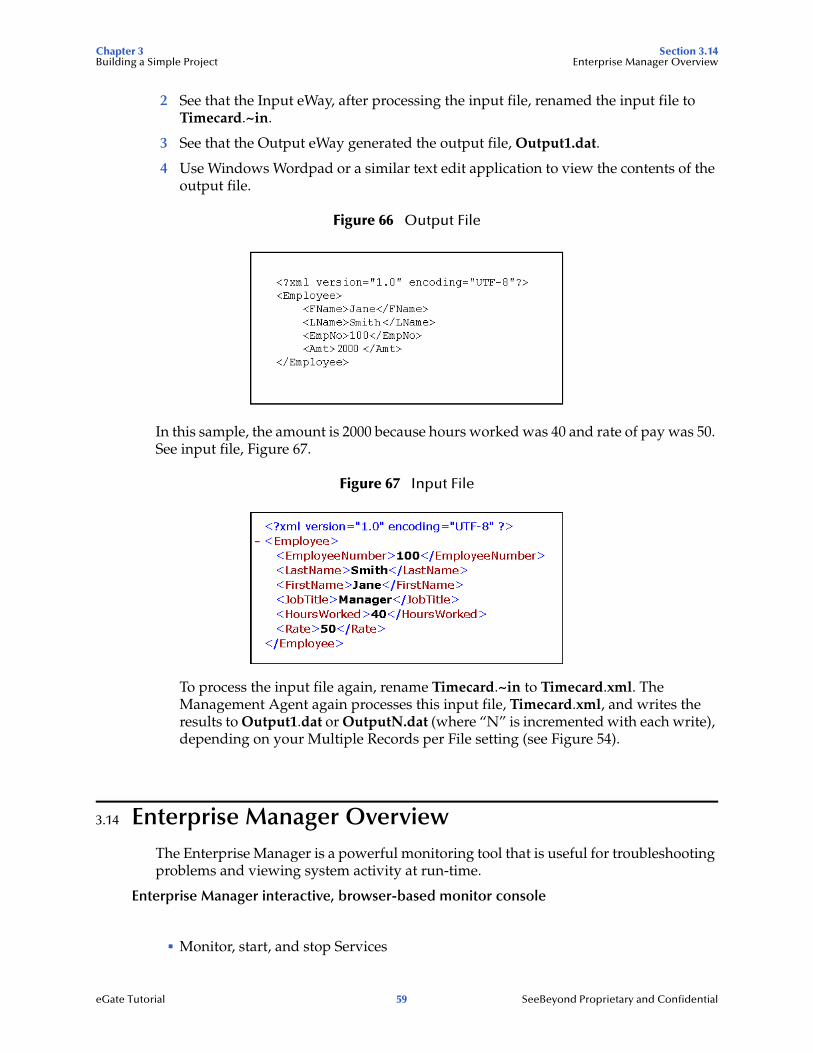
Figure 66 Output File
In this sample, the amount is 2000 because hours worked was 40 and rate of pay was 50. See input file, Figure 67.
Figure 67 Input File
To process the input file again, rename Timecard.~in to Timecard.xml. The Management Agent again processes this input file, Timecard.xml, and writes the results to Output1.dat or OutputN.dat (where “N” is incremented with each write), depending on your Multiple Records per File setting (see Figure 54).
3.14 Enterprise Manager OverviewThe Enterprise Manager is a powerful monitoring tool that is useful for troubleshooting problems and viewing system activity at run-time.
Enterprise Manager interactive, browser-based monitor console
! Monitor, start, and stop Services
eGate Tutorial 59 SeeBeyond Proprietary and Confidential
Chapter 3 Section 3.15Building a Simple Project Starting and Using Enterprise Manager
! Monitor JMS topics
! View and edit messages
! View and edit message payloads
! Monitor system logs
! Monitor and manage system alerts
! Monitor eInsight Business Processes (if licensed)
3.14.1 When to Use the Monitor Enterprise Manager will notify you by flashing the affected component node structure when:
! There is a problem within the Project
! You have stopped a server within a Project or Environment, or stopped an object in a Connectivity map
3.14.2 Using Project View Project view allows you to perform run-time monitoring and management of Deployments and Connectivity Maps.
3.14.3 Using Environment ViewEnvironment view allows you to perform run-time monitoring and management of eGate and eInsight System components.
3.14.4 Locating the Problem NodeWhen a problem occurs, the Project node is decorated with a flashing highlight, which is propagated upward from the problem node. When you expand the tree, the problem node will be highlighted and will also have a flashing exclamation point appended to it. The exclamation point association visually calls out the target node (or nodes) for troubleshooting the problem.
3.15 Starting and Using Enterprise ManagerStart Enterprise Manager
1 Start Enterprise Manager and type your username and password.
2 Click Login.
3 Click the Home tab.
4 Double-click Monitor.
eGate Tutorial 60 SeeBeyond Proprietary and Confidential
Chapter 3 Section 3.15Building a Simple Project Starting and Using Enterprise Manager
You can click the Project tab or the Environment tab to monitor the state of the Logical Host(s) and the Project components deployed in them. You can also view the logs and change the log levels of the Logical Host.
It is beyond the scope of this tutorial to explain all the capabilities of the Enterprise Manager. The following examples demonstrate a few of its capabilities.
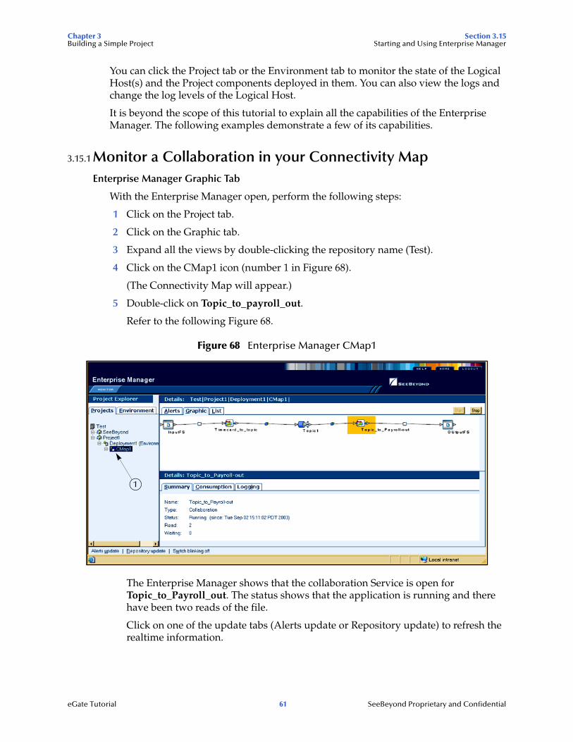
3.15.1 Monitor a Collaboration in your Connectivity MapEnterprise Manager Graphic Tab
With the Enterprise Manager open, perform the following steps:
1 Click on the Project tab.
2 Click on the Graphic tab.
3 Expand all the views by double-clicking the repository name (Test).
4 Click on the CMap1 icon (number 1 in Figure 68).
(The Connectivity Map will appear.)
5 Double-click on Topic_to_payroll_out.
Refer to the following Figure 68.
Figure 68 Enterprise Manager CMap1
The Enterprise Manager shows that the collaboration Service is open for Topic_to_Payroll_out. The status shows that the application is running and there have been two reads of the file.
Click on one of the update tabs (Alerts update or Repository update) to refresh the realtime information.
1
eGate Tutorial 61 SeeBeyond Proprietary and Confidential
Chapter 3 Section 3.15Building a Simple Project Starting and Using Enterprise Manager
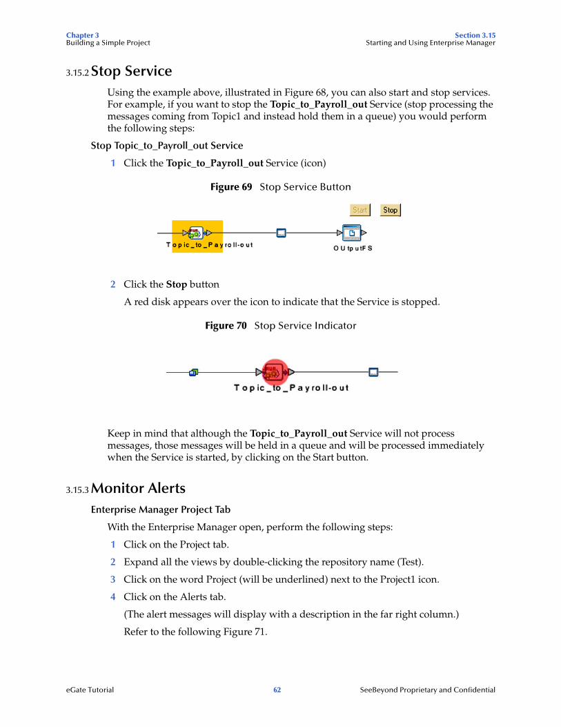
3.15.2 Stop ServiceUsing the example above, illustrated in Figure 68, you can also start and stop services. For example, if you want to stop the Topic_to_Payroll_out Service (stop processing the messages coming from Topic1 and instead hold them in a queue) you would perform the following steps:
Stop Topic_to_Payroll_out Service
1 Click the Topic_to_Payroll_out Service (icon)
Figure 69 Stop Service Button
2 Click the Stop button
A red disk appears over the icon to indicate that the Service is stopped.
Figure 70 Stop Service Indicator
Keep in mind that although the Topic_to_Payroll_out Service will not process messages, those messages will be held in a queue and will be processed immediately when the Service is started, by clicking on the Start button.
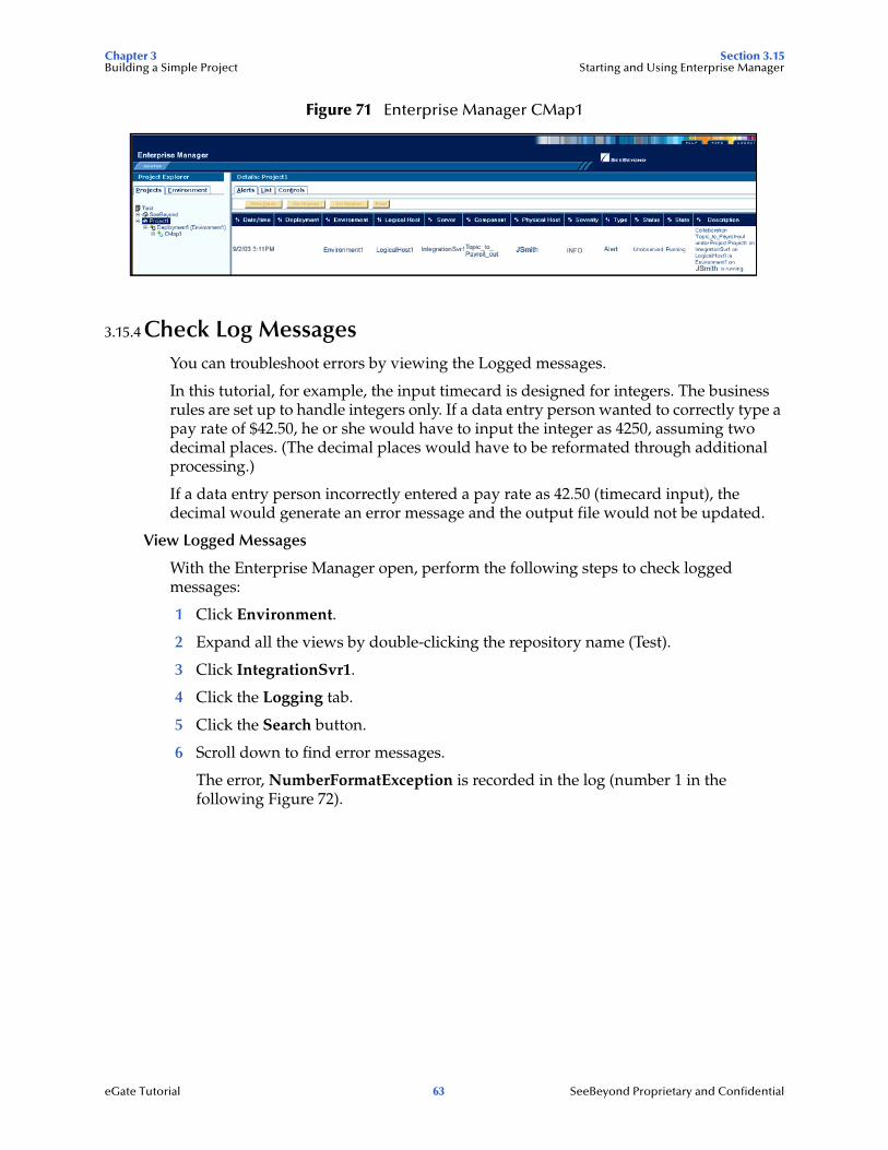
3.15.3 Monitor AlertsEnterprise Manager Project Tab
With the Enterprise Manager open, perform the following steps:
1 Click on the Project tab.
2 Expand all the views by double-clicking the repository name (Test).
3 Click on the word Project (will be underlined) next to the Project1 icon.
4 Click on the Alerts tab.
(The alert messages will display with a description in the far right column.)
Refer to the following Figure 71.
eGate Tutorial 62 SeeBeyond Proprietary and Confidential
Chapter 3 Section 3.15Building a Simple Project Starting and Using Enterprise Manager
Figure 71 Enterprise Manager CMap1
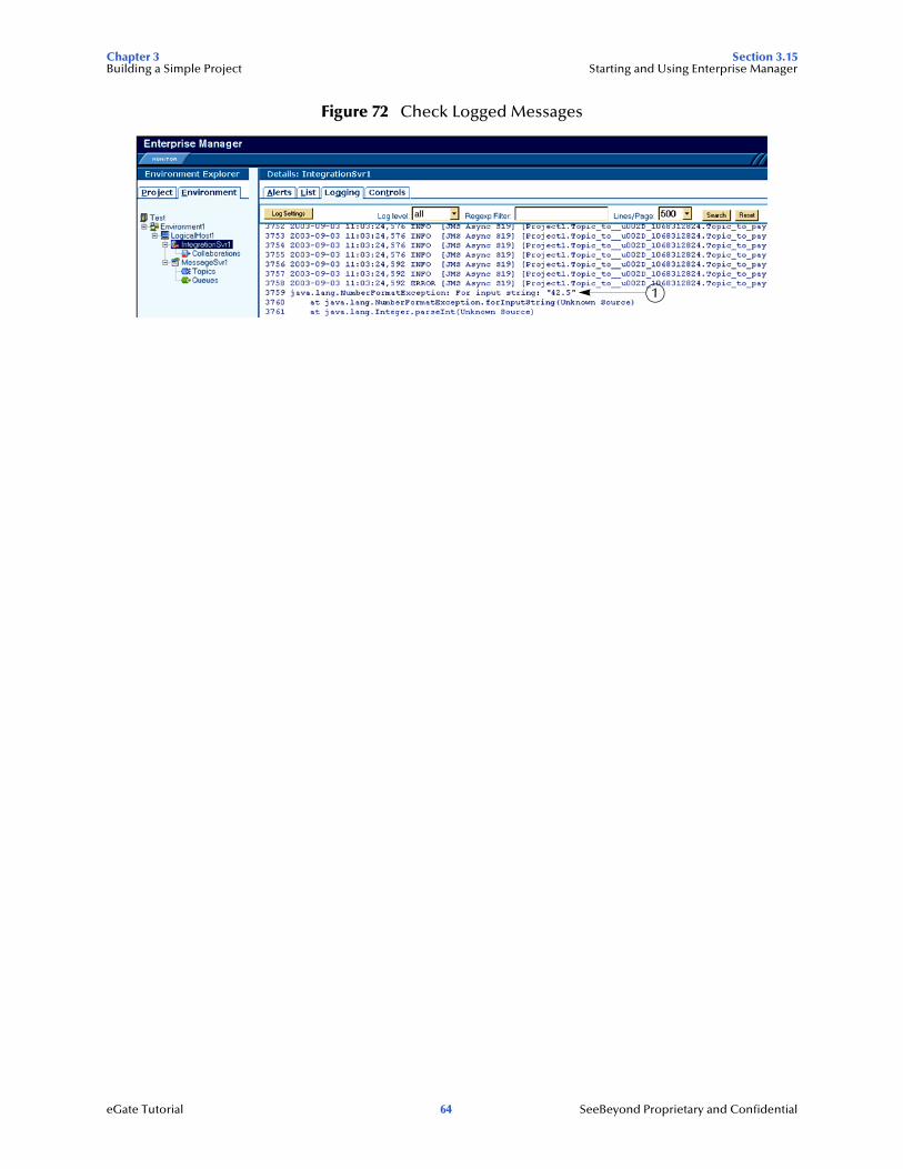
3.15.4 Check Log MessagesYou can troubleshoot errors by viewing the Logged messages.
In this tutorial, for example, the input timecard is designed for integers. The business rules are set up to handle integers only. If a data entry person wanted to correctly type a pay rate of $42.50, he or she would have to input the integer as 4250, assuming two decimal places. (The decimal places would have to be reformated through additional processing.)
If a data entry person incorrectly entered a pay rate as 42.50 (timecard input), the decimal would generate an error message and the output file would not be updated.
View Logged Messages
With the Enterprise Manager open, perform the following steps to check logged messages:
1 Click Environment.
2 Expand all the views by double-clicking the repository name (Test).
3 Click IntegrationSvr1.
4 Click the Logging tab.
5 Click the Search button.
6 Scroll down to find error messages.
The error, NumberFormatException is recorded in the log (number 1 in the following Figure 72).
eGate Tutorial 63 SeeBeyond Proprietary and Confidential
Chapter 3 Section 3.15Building a Simple Project Starting and Using Enterprise Manager
Figure 72 Check Logged Messages
1
eGate Tutorial 64 SeeBeyond Proprietary and Confidential
Glossary
Glossary
Collaboration(See Service and Collaboration Definition.)
Collaboration DefinitionThe encoding of business rules, in Java or XSLT format. Typically, the encoding consists of operations on OTDs (see “OTD” on page 67). Several Collaborations can have the same Collaboration Definition.
ConnectionConsists of the configuration information that enables an eWay to connect to an external system.
Connectivity MapContains business logic and routing information about the data transmission. A Connectivity Map usually includes one or more Collaborations, Passthrough Collaborations, topics, queues, and eWays. A Connectivity Map is created under a Project. A Project may have multiple Connectivity Maps.
ConstantsA name or value pair that is visible across a Project.
Deployment ProfileContains the information about how the Project components will be deployed in an Environment. A Project can have multiple Deployment Profiles, but only one Deployment Profile can be activated for a Project in any one Environment.
Derived CollaborationCollaboration that inherits operations from another, according to standard object-oriented practice.
eGate SystemSee “Project”.
EnvironmentA collection of physical resources and their configurations that are used to host Project components. An Environment contains logical hosts and external systems.
eView Manager ServiceA component of an eView master index that provides an interface to all components and includes the primary functions of the master index.
eWayA link between a Collaboration and an external connection including the message server connection (topic or queue) or external application.
eGate Tutorial 65 SeeBeyond Proprietary and Confidential
Glossary
External ApplicationA logical representation of an external application.
External SystemA representation of an external application system.
ICAN SuiteThe SeeBeyond Integrated Composite Application Network Suite, which is based on eGate Integrator.
Integration ServerSoftware platform that houses the business logic container used to run Collaborations. Provides transaction services, persistence, and external connectivity.
LinkThe JMS Connection between a Collaboration and a topic or queue in a JMS-compliant message server.
Linked Message DestinationA reference to a Message Destination defined in another Connectivity Map.
Logical HostAn instance of the eGate runtime Environment that is installed on a machine. A Logical Host contains the software and other installed components that are required at runtime, such as application and message servers.
Management AgentUses J2EE technology to manage and monitor an eGate 5.0 deployment that may contain other application servers in addition to the SeeBeyond Integration Server. Defines management interfaces and services designed for distributed environments, focusing on providing functionality for managing networks, systems, and applications.
master indexA database application that stores and cross-references information on specific objects in a business organization, regardless of the computer system from which the information originates. Also called enterprise-wide master index.
Matching ServiceA component of an eView master index that contains the logic for the matching process.
Message DestinationA general term for a topic or queue. Two or more Projects can share a message destination that has the same name and is deployed on the same message server. A single Project may also have a single message destination referenced in multiple Connectivity Maps.
Message ServerJMS-compliant, guaranteed delivery store, forwarding, and queueing service.
eGate Tutorial 66 SeeBeyond Proprietary and Confidential
Glossary
OTDAn acronym for Object Type Definition. OTDs contain the data structure and rules that define an object. An OTD is used in Java Collaboration Definitions for creating data transformations and interfacing with external systems.
ProjectContains a collection of logical components, configurations, and files that are used to solve business problems. A Project organizes the files and packages and maintains the settings that comprise an eGate system in SeeBeyond’s Enterprise Designer.
Query BuilderA component of an eView master index that defines how queries are processed.
QueueA JMS queue is a shareable object that conforms to the point-to-point (p2p, or PTP) messaging domain, where one sender delivers a message to exactly one receiver. When the SeeBeyond Message Server sends a message to a queue, it ensures it is received once and only once, even though there may be many receivers “listening” to the queue. This is equivalent to the subscriber pooling in other queue implementations. You can reference a queue that exists in another Connectivity Map or Project.
RepositoryStores and manages the setup, component, and configuration information for eGate Projects. The Repository also provides monitoring services for Projects, which include version control and impact analysis.
Schema Runtime EnvironmentAn add-on in eGate 5.0 that provides the upgrade path for e*Gate 4.x users to upgrade to eGate 5.0. Also known as the SRE.
Security ServerA standalone server that is the connection point to underlying eGate security environments.
ServiceContains the information about executing a set of business rules. These business rules can be defined in a Java Collaboration Definition, XSLT Collaboration Definition, Business Process, eTL Definition, or other service. A Service also contains binding information for connecting to JMS Topics, Queues, eWays, and other services.
single best recordAlso known as the SBR, this is the best representation of an entity’s information in an eView master index. The SBR is populated with information from all source systems based on the survivor strategies defined for each field.
SubprojectAn independent Project that is included as part of another Project and listed on the Enterprise Explorer tree beneath the main Project icon.
eGate Tutorial 67 SeeBeyond Proprietary and Confidential
Glossary
TopicA JMS topic is a shareable object that conforms to the publish-and-subscribe (pub/sub) messaging domain, where one publisher broadcasts messages to potentially many subscribers. When the SeeBeyond Message Server publishes a message on a topic, it ensures that all subscribers receive the message.
XSLT
An acronym for Extensible Stylesheet Language Transformations. A file format used in eGate to generate Collaboration Definitions.
Update ManagerA component of an eView master index that contains the Java classes and logic that determine how records are updated and how the single best record is populated.
eGate Tutorial 68 SeeBeyond Proprietary and Confidential

Glossary
e*Gate 4.x Terms in eGate 5.0
Table 2 provides definitions for the terms that are new with eGate release 5.0, as well as equivalent terms from eGate release 4.x.
Table 2 eGate 5.0 Terms
5.0 Term 4.x Equivalent Term
Collaboration Collaboration
Collaboration Definition
Collaboration Definition
Connection e*Way Connection
Connectivity Map Closest: Network View of an entire Schema
Deploy Run the Control Broker
Deployment <none>
Deployment Profile Closest: Schema
Enterprise Designer Enterprise Manager
Enterprise Manager Enterprise Monitor
Environment Schema (except only includes physical information, not business logic)
eWay e*Way Connectione*Way
eWay Configuration e*Way Connection Configuration
External Application e*Way Connection
External System e*Way Connection
JMS Connection e*Way Connection
Integration Server <none>
Link JMS e*Way Connection
Linked Message Destination
<none>
Logical Host Participating Host
Message Destination Topic or queue
Message Server JMS IQ Manager
Object Type Definition (OTD)
Event Type Definition (ETD)
Process Manager Control Broker
Project Schema (except not including physical layer)
Queue JMS queue
Repository Registry
Subproject Schema
eGate Tutorial 69 SeeBeyond Proprietary and Confidential

Glossary
Topic JMS topic
XSLT <none>
Table 2 eGate 5.0 Terms (Continued)
5.0 Term 4.x Equivalent Term
eGate Tutorial 70 SeeBeyond Proprietary and Confidential
Index
Index
AAdjust window size 42
BBootstrap Command 57
Example 58Business Rules
Apply 30Business Rules Designer window 29Business Rules pane (see note) 40Multiplication logic 38Objects - in the Business Rules Designer window
(see note) 34
CCall Java Method 41Call New Constructor 43Class Name box 41Collaboration 65, 69
derived 65Collaboration definition 65, 69connection 65, 69Connectivity Map 65, 69
Add components 19Create 18Default name, CMap1 18Defined in a project 10Graphic 13Graphic, unlinked 47Link components 47
constants 65Control Broker 69conventions
path name separator 6Windows 6
Ddeploy 69Deployment 69Deployment Profile 65, 69Deployment Profile Editor
Defined in a project 10derived Collaboration 65document
conventions 6
Ee*Way 69e*Way Connection 69e*Way Connection Configuration 69eGate system 65Enterprise Designer 69
Create a new project 16Create and configure components 8Deploy your project 56Editor 10Features 8GUI 9Menu Bar 9Project 10Start the Enterprise Designer 17
Enterprise ExplorerCreate a connectivity map 18Create and name a project 17Organize components, in the left pane 10The left pane of the Enterprise Designer 9Tree 38
Enterprise Manager 69Check log messager 63Flashing indicators 60Monitor a Collaboration 61Monitor Alerts 62Overview 59Problem Node 60Starting and using 60Stop a Service 62
Enterprise Monitor 69Environment 65, 69
Activate 56Bootstrap 57Create environment 53Defined in a project 10Deployment profile 54in Enterprise Manager 60LogicalHost1 53Message server 55New File External System 53–54Populate 55
Environment ExplorerAccessed from View menu 9Collection of logical hosts 10Create environment 53
error messages 25ETD 69Event Type Definition 69eWay 65, 69
Configure 49Graphic 50Input eWay 49
eGate Tutorial 71 SeeBeyond Proprietary and Confidential
Index
Link between External Application and a Service 47
Output eWay 49eWay Configuration 69external
application 66, 69system 66, 69
External Applications 19
GGUI
Graphical User Interface 5
IICAN Suite 66Input
Inbound eWay 13Input file 59Input.dtd, create input file 15InputFS 13
Integer 41Integration Server 66, 69Introduction 5, 8
JJava Collaboration Editor
Defined in a project 10JMS
connection 69e*Way Connection 69IQ Manager 69JMS Client Configuration 51queue 69topic 70
Llink 66, 69linked message destination 66, 69Logical Host 52, 66, 69Login
Login menu 17
MManagement Agent 66Menu Bar 9message
destination 66, 69server 66, 69
Multiple records 51Multiplication Operation
Graphic 44Method box 42Operator 42
Nnetwork view 69Nodes
Connect 40nodes 40
OObject Type Definition 21, 67, 69OTD 67, 69OTD Editor
Defined in a project 10Output
Outbound eWay 13Output file 59Output.dtd, create output file 16OutputFS 13
PParticipating Host 69Polling interval 51Process Manager 69Project 67, 69
Bootstrap command 58Configure eWays 49Configure input 26Configure output 34Create 16Create and name 17Create OTD 21Create path to data 50Default name, Project1 18Deploy and activate 56Deployment 53Deployment profile 54Drop down arrow 37Graphic, showing components 47in Enterprise Manager 60Overview 12Run bootstrap and management agent 57Verify output 58
Project Diagram 14Project Editor
Part of Enterprise Designer 10Properties configuration 50
eGate Tutorial 72 SeeBeyond Proprietary and Confidential
Index
Qqueue 67, 69
RRegistry 69Repository 67, 69Rules 29Run Test 24Run Tester icon 25
SSample Data 15Save
Save 23Save All 23
Schema 69Schema Runtime Environment 67Security Server 67Service 26
file-read service 27Web service 28wizards 26Write 28
SRE 67Status tab 25subproject 67, 69supporting documents 5
TTime Card system 15Timecard_to_topic 13Topic
Create a Topic 20Topic1 13
topic 68–70Topic_to_Payroll_out 13
UUnmarshal Text 39
WWindows 15
The Bootstrap command is case sensitive on Windows 57
tutorial runs on a Windows system 5Windows Explorer 15
writing conventions 6
XXML
data 49file 49
XSLT 68, 70XSLT Collaboration Editor
Defined in a project 10
eGate Tutorial 73 SeeBeyond Proprietary and Confidential