efotg.sc.egov.usda.govefotg.sc.egov.usda.gov/references/public/id/fy13_practicescenario... · xls...
TRANSCRIPT

Practice Name Component
313 - Waste Storage Facility 1
313 - Waste Storage Facility 2
313 - Waste Storage Facility 3
313 - Waste Storage Facility 4
313 - Waste Storage Facility 5
ScenarioNumber
Earthen Storage Facility < 50K ft3 Storage
Earthn Storage Facility>50K ft3 Storage
Earthen Storage FacilityHigh Water Table
Above Ground Steel/Concrete < 25K ft3 storage
Above Ground Steel/Concrete 25-100K ft3 storage

313 - Waste Storage Facility 6
313 - Waste Storage Facility 7 Drystack,earthen floor,no wall
313 - Waste Storage Facility 8 Dry stack, earthen floor, wood wall
313 - Waste Storage Facility 9
313 - Waste Storage Facility 10 Dry Stack, concrete floor, no wall
313 - Waste Storage Facility 11 Dry Stack, concrete floor, wood wall
Above Ground Steel/Concrete >100K ft3 storage
Dry Stack, earthen floor, concrete wall

313 - Waste Storage Facility 12
313 - Waste Storage Facility 13 Conc Tank, buried <5K, wi lid
313 - Waste Storage Facility 14 Conc Tank, buried 5K<15K, wi lid
313 - Waste Storage Facility 15 Conc Tank, Buried 15K<25K, wi lid
313 - Waste Storage Facility 16 Conc Tank, Buried 25K<50K, wi lid
313 - Waste Storage Facility 17 Conc Tank, Buried 50K<75K, wi lid
313 - Waste Storage Facility 18 Conc Tank, Buried 75K<110K, wi lid
Dry Stack, concrete floor, concrete wall

313 - Waste Storage Facility 19 Conc Tank, Buried 110K or > wi lid
313 - Waste Storage Facility 20
313 - Waste Storage Facility 21 Conc Tank, buried <5K
313 - Waste Storage Facility 22 Open Conc Tank, buried 5K<15K
313 - Waste Storage Facility 23 Open Conc Tank, Buried 15K<25K
313 - Waste Storage Facility 24 Open Conc Tank, Buried 25K<50K
313 - Waste Storage Facility 25 Open Conc Tank, Buried 50K<75K
Composted Bedded Pack, Concrete Floor, Concrete Wall

313 - Waste Storage Facility 26 Open Conc Tank, Buried 75K<110K
313 - Waste Storage Facility 27 Open Conc Tank, Buried 110K or >
314 - Brush Management 1 Mechanical, Hand tools
314 - Brush Management 2 Mechanical Light Equipment
314 - Brush Management 3
314 - Brush Management 4 Mechanical and Chemical
314 - Brush Management 5
314 - Brush Management 6 Chemical - Ground Applied
314 - Brush Management 7 Chemical, Aerial Fixed Wing
Mechanical, Large Shrubs, Medium Infestation
Mechanical & Chemical, Cut stump plus chemical treatment, pile & burn, chip, etc

315 - Herbaceous Weed Control 1 Biological Control - Targeted Grazing
315 - Herbaceous Weed Control 2 Mechanical, Hand
315 - Herbaceous Weed Control 3 Mechanical
315 - Herbaceous Weed Control 4 Chemical, Spot
315 - Herbaceous Weed Control 5 Chemical, Ground
315 - Herbaceous Weed Control 6 Chemical, Aerial
315 - Herbaceous Weed Control 7 Biological - Insects
317 - Composting Facility 1
317 - Composting Facility 2
Composter, with concrete under wood bins (wood or concrete) only
Composter, concrete floor with concrete bins

317 - Composting Facility 3
317 - Composting Facility 4
320 - Irrigation Canal or Lateral 1 Irrigation Canal
320 - Irrigation Canal or Lateral 2 Relocate Canal or Lateral
324 - Deep Tillage 1 Deep Tillage less than 36 inches
324 - Deep Tillage 2 Deep Tillage more than 36 inches
326 - Clearing and Snagging 1 Clearing and Snagging - Light
326 - Clearing and Snagging 2 Clearing and Snagging - Medium
326 - Clearing and Snagging 3 Clearing and Snagging - Heavy
Composter, windrow, all weather surface
Composter, with compacted earth floor, windrow

327 - Conservation Cover 1 Introduced Grass
327 - Conservation Cover 2 Native Grass
327 - Conservation Cover 3 Orchard or Vineyard Alleyways
327 - Conservation Cover 4 Pollinator Habitat
327 - Conservation Cover 5 Organic Introduced Mix
327 - Conservation Cover 6 Organic Native Mix

327 - Conservation Cover 7 Organic Pollinator Habitat
328 - Conservation Crop Rotation 1 Standard Rotation
328 - Conservation Crop Rotation 2 Irrigated to Dryland Rotation

328 - Conservation Crop Rotation 3 Organic Rotation
328 - Conservation Crop Rotation 4 Specialty Crops
328 - Conservation Crop Rotation 5 Organic Specialty Crops
328 - Conservation Crop Rotation 6 End gun removal

1 No-Till/Strip-Till
2 Organic No-Till/Strip-Till
330 - Contour Farming 1 Contour Farming
332 - Contour Buffer Strips 1 332-Native, Inc Forgone
332 - Contour Buffer Strips 2 332-Introduced, Inc Forgone
332 - Contour Buffer Strips 3 332-Wildlife/Pollinator, Inc Forgone
329 - Residue and Tillage Management - No-Till/ Strip Till/ Direct Seed
329 - Residue and Tillage Management - No-Till/ Strip Till/ Direct Seed

332 - Contour Buffer Strips 4 332-Organic Seed, Inc Forgone
338 - Prescribed Burning 1 Understory Burn
338 - Prescribed Burning 2 Site Preparation
338 - Prescribed Burning 3 Pile Burning
338 - Prescribed Burning 4
338 - Prescribed Burning 5
338 - Prescribed Burning 6
Level Terrain, Herbaceous Fuel < 640 ac.
Level Terrain - Herbaceous Fuel >640 ac.
Level Terrain, Volatile fuels < 4 ft tall, <640 ac

338 - Prescribed Burning 7
338 - Prescribed Burning 8
338 - Prescribed Burning 9
340 - Cover Crop 1 Cover Crop-Chemical Kill
340 - Cover Crop 2 Cover Crop-Mechanical Kill
Level Terrain, Volatile fuels < 4 ft tall, >640 ac
Level Terrain, Volatile fuels > 4 ft tall, <640 ac
Level Terrain, Volatile fuels > 4 ft tall, >640 ac

340 - Cover Crop 3 Legume-N Fixation
340 - Cover Crop 4
340 - Cover Crop 5 Organic Cover Crop
342 - Critical Area Planting 1 Introduced species - drilled
342 - Critical Area Planting 2
342 - Critical Area Planting 3 Native species - drilled
342 - Critical Area Planting 4
342 - Critical Area Planting 5 Native seeding-moderate grading
Orchard/Vineyard Annual Cover Crop
Organic Grass/legume mix-normal tillage
Grass/legume mix-moderate grading

342 - Critical Area Planting 6 Introduced species aerial applied
342 - Critical Area Planting 7 Native species broadcast rate
342 - Critical Area Planting 8 Introduced species broadcast rate
342 - Critical Area Planting 9 Native species aerial applied
345 - Res. & Tillage Mgt, Mulch-till 1 Mulch Till, Dryland
345 - Res. & Tillage Mgt, Mulch-till 2 Mulch Till, Irrigated

1 Ridge Till
348 - Dam Diversion 1 Rock/Gravel Fill
348 - Dam Diversion 2 Earth Fill
348 - Dam Diversion 3 Earth Fill-Grouted Rock
348 - Dam Diversion 5 Reinforced Concrete Dam Diversion
348 - Dam Diversion 7 Rock Structure
348 - Dam Diversion 8 Concrete Structure
346 - Residue and Tillage Management - Ridge Till

348 - Dam Diversion 9 Wood Structure
350 - Sediment Basin 1 Excavated volume
350 - Sediment Basin 2
350 - Sediment Basin 3
355 - Well Water Testing 1 Basic Water Quality Test
355 - Well Water Testing 2 Specialized Water Quality Test
355 - Well Water Testing 3 Full Spectrum Water Quality Test
Embankment earthen basin with no pipe
Embankment, Earthen Basin with Pipe

356 - Dike 1 Material haul < 1 mile
356 - Dike 2 Material haul > 1 mile
359 - Waste Treatment Lagoon 1 Waste Treatment Lagoon
362 - Diversion 2 Diversion, Concrete
362 - Diversion 3 Diversion, Earthfill
362 - Diversion 4 Diversion, Excavation
362-Diversion 1 Diversion (cubic yard)

366 - Anaerobic Digester 1 Small Plug Flow <1000 AU
366 - Anaerobic Digester 2 Medium Plug Flow 1000-2000 AU
366 - Anaerobic Digester 3 Large Plug Flow >2000 AU
366 - Anaerobic Digester 4 Small Complete Mix <1000 AU
366 - Anaerobic Digester 5
366 - Anaerobic Digester 6 Large Complete Mix >2,500 AU
Medium Complete Mix 1000-2500 AU

366 - Anaerobic Digester 7 Covered Lagoon/Holding Pond
367 - Roofs and Covers 1 Flexible Roof
367 - Roofs and Covers 2 Timber or Steel Sheet Roof
367 - Roofs and Covers 3 Steel Frame and Roof
367 - Roofs and Covers 4 Flexible Membrane Cover
367 - Roofs and Covers 6
1
2
Permeable Composite or Inorganic Cover
372 - Combustion System Improvement
Electric Motor in-lieu of IC Engine, < 37 kW
372 - Combustion System Improvement
Electric Motor in-lieu of IC Engine, 37 to 73 kW

3
4
5
1 Lighting - CFL
2 Lighting - LED
3 Lighting - Linear Fluorescent
4 Ventilation - Exhaust
5 Ventilation - HAF
6 Plate Cooler
7 Scroll Compressor
372 - Combustion System Improvement
Electric Motor in-lieu of IC Engine, 74 to 148 kW
372 - Combustion System Improvement
Electric Motor in-lieu of IC Engine, 148 to 295 kW
372 - Combustion System Improvement
Electric Motor in-lieu of IC Engine, > 295 kW
374 - Farmstead Energy Improvement
374 - Farmstead Energy Improvement
374 - Farmstead Energy Improvement
374 - Farmstead Energy Improvement
374 - Farmstead Energy Improvement
374 - Farmstead Energy Improvement
374 - Farmstead Energy Improvement

8 Variable Speed Drive > 5 HP
9 Automatic Controller System
10 Motor Upgrade > 100 HP
11 Motor Upgrade 10 - 100 HP
12 Motor Upgrade > 1 and < 10 HP
13 Motor Upgrade ≤ 1 HP
14 Heating - Radiant Tube
15 Heating (Building)
16 Attic Insulation
374 - Farmstead Energy Improvement
374 - Farmstead Energy Improvement
374 - Farmstead Energy Improvement
374 - Farmstead Energy Improvement
374 - Farmstead Energy Improvement
374 - Farmstead Energy Improvement
374 - Farmstead Energy Improvement
374 - Farmstead Energy Improvement
374 - Farmstead Energy Improvement

17 Wall Insulation
18 Sealant
19 Greenhouse Screens
20 Grain Dryer
1 Manure Harvesting - Once per Year
2 Manure Harvesting - Twice per Year
3
4
5
6
7
8
374 - Farmstead Energy Improvement
374 - Farmstead Energy Improvement
374 - Farmstead Energy Improvement
374 - Farmstead Energy Improvement
375 - Dust Control from Animal Activity on Open Lot Surfaces
375 - Dust Control from Animal Activity on Open Lot Surfaces
375 - Dust Control from Animal Activity on Open Lot Surfaces
Manure Harvesting - More Than Twice per Year
375 - Dust Control from Animal Activity on Open Lot Surfaces
Solid-Set Sprinkler System, Less than 20 Acres
375 - Dust Control from Animal Activity on Open Lot Surfaces
Solid-Set Sprinkler System, 20-60 Acres
375 - Dust Control from Animal Activity on Open Lot Surfaces
Solid-Set Sprinkler System, Greater than 60 Acres
375 - Dust Control from Animal Activity on Open Lot Surfaces
Truck-Mounted Mobile Sprinkler System
375 - Dust Control from Animal Activity on Open Lot Surfaces
Manure Harvest-1 per Year and Solid-Set Sprinkler System, Less than 20 Acres

9
10
11
12
13
14
15
16
17
18
19
20 Solid-Set Sprinkler System Labor
375 - Dust Control from Animal Activity on Open Lot Surfaces
Manure Harvest-1 per Year and Solid-Set Sprinkler System, 20-60 Acres
375 - Dust Control from Animal Activity on Open Lot Surfaces
Manure Harvest-1 per Year and Solid-Set Sprinkler System, Greater than 60 Acres
375 - Dust Control from Animal Activity on Open Lot Surfaces
Manure Harvest-1 per Year and Truck-Mounted Mobile Sprinkler System
375 - Dust Control from Animal Activity on Open Lot Surfaces
Manure Harvest-2 per Year and Solid-Set Sprinkler System, Less than 20 Acres
375 - Dust Control from Animal Activity on Open Lot Surfaces
Manure Harvest-2 per Year and Solid-Set Sprinkler System, 20-60 Acres
375 - Dust Control from Animal Activity on Open Lot Surfaces
Manure Harvest-2 per Year and Solid-Set Sprinkler System, Greater than 60 Acres
375 - Dust Control from Animal Activity on Open Lot Surfaces
Manure Harvest-2 per Year and Truck-Mounted Mobile Sprinkler System
375 - Dust Control from Animal Activity on Open Lot Surfaces
Manure Harvest-More Than Twice per Year and Solid-Set Sprinkler System, Less than 20 Acres
375 - Dust Control from Animal Activity on Open Lot Surfaces
Manure Harvest-More Than Twice per Year and Solid-Set Sprinkler System, 20-60 Acres
375 - Dust Control from Animal Activity on Open Lot Surfaces
Manure Harvest-More Than Twice per Year and Solid-Set Sprinkler System, Greater than 60 Acres
375 - Dust Control from Animal Activity on Open Lot Surfaces
Manure Harvest-More Than Twice per Year and Truck-Mounted Mobile Sprinkler System
375 - Dust Control from Animal Activity on Open Lot Surfaces

21
22
23
378 - Pond 1 Excavated Pit
378 - Pond 2 Embankment Pond without Pipe
378 - Pond 3
378 - Pond 4
380 - Windbreak/Shelterbelt Est. 1
380 - Windbreak/Shelterbelt Est. 2
380 - Windbreak/Shelterbelt Est. 3
380 - Windbreak/Shelterbelt Est. 4
375 - Dust Control from Animal Activity on Open Lot Surfaces
Manure Harvest-1 per Year and Solid-Set Sprinkler System Labor
375 - Dust Control from Animal Activity on Open Lot Surfaces
Manure Harvest-2 per Year and Solid-Set Sprinkler System Labor
375 - Dust Control from Animal Activity on Open Lot Surfaces
Manure Harvest-More Than Twice per Year and Solid-Set Sprinkler System Labor
Embankment Pond with Metal or Plastic Pipe (CMP or HDPE)
Embankment Pond with Pipe, CMP Riser & HDPE Barrel
1 row windbreak, shrubs, hand planted
1 row windbreak, trees, hand planted
2-row windbreak, shrubs, machine planted
2-row windbreak, trees, machine planted

380 - Windbreak/Shelterbelt Est. 5
380 - Windbreak/Shelterbelt Est. 6
380 - Windbreak/Shelterbelt Est. 7
380 - Windbreak/Shelterbelt Est. 8
380 - Windbreak/Shelterbelt Est. 9382 - Fence 1 Barbed/Smooth Wire
382 - Fence 2 Wire Difficult
382 - Fence 3 Woven Wire
382 - Fence 4 Electric
382 - Fence 5 Confinement
2-row windbreak, trees, machine planted
3 or more row windbreak, shrub, machine planted
3 or more tree rows machine planted windbreak
3 or more row windbreak, trees, machine planted
Per plant 3 or more rows machine planted windbreak

382 - Fence 6 Safety
382 - Fence 7 Wildlife Exclusion
382 - Fence 8 Livestock Protection
383 - Fuel Break 7 Structure
383 - Fuel Break 8 Forested
384 - Woody Residue Treatment 1
384 - Woody Residue Treatment 2 Chipping and hauling off-site
384 - Woody Residue Treatment 3 Pile and Burn386 - Field Border 1 Field Border-Native, Inc Forgone
386 - Field Border 2
Woody residue/silvicultural slash treatment- light
Field Border, Introduced, Inc Forgone

386 - Field Border 3 Field Border-Pollinator, Inc Forgone
386 - Field Border 4 Field Border-Tree, Inc. Forgone
386 - Field Border 5
388 - Irrigation Field Ditch 1 Irrigation Field Ditch
390 - Riparian Herbaceous Cover 1 Aquatic Wildlife
Field Border-Organic Seed, Inc Forgone

390 - Riparian Herbaceous Cover 2 Plugging and Seeding
390 - Riparian Herbaceous Cover 3 Cool Season Grasses w/ Forbs

391 - Riparian Forest Buffer 5 Small container, hand planted393 - Filter Strip 1
393 - Filter Strip 2
393 - Filter Strip 3
393 - Filter Strip 4
394 - Firebreak 1 Constructed - Light Equipment
394 - Firebreak 2
394 - Firebreak 3
394 - Firebreak 4 Vegetated permanent firebreak
394 - Firebreak 5
Filter Strip, Native species: Forgone Income
Filter Strip, Introduced species: Forgone Income
Filter Strip, Native Species w/ Land Shaping: Forgone Income
Filter Strip, Introduced Species w/ Land Shaping: Forgone Income
Constructed - Medium equipment, flat-medium slopes
Constructed - Medium equipment, steep slopes
Constructed - Wide, bladed or disked firebreak

395 - Stream Habitat Improvement 1
395 - Stream Habitat Improvement 2 Instream wood placement
Riparian Zone Improvement-Forested

395 - Stream Habitat Improvement 3 Instream rock placement

395 - Stream Habitat Improvement 4 Rock and wood structures
395 - Stream Habitat Improvement 5 Fish Barrier

396 - Aquatic Organism Passage 1 Concrete Dam Removal

396 - Aquatic Organism Passage 2 Earthen Dam Removal

396 - Aquatic Organism Passage 3 Blockage Removal

396 - Aquatic Organism Passage 4 Nature-Like Fishway

396 - Aquatic Organism Passage 5 CMP Culvert

396 - Aquatic Organism Passage 6 Bottomless Culvert

396 - Aquatic Organism Passage 7 Concrete Box Culvert

396 - Aquatic Organism Passage 8 Bridge

396 - Aquatic Organism Passage 9 Concrete Ladder

396 - Aquatic Organism Passage 10 Complex Denil

396 - Aquatic Organism Passage 11 Alaskan Steeppass

396 - Aquatic Organism Passage 12 Low Water Crossing

396 - Aquatic Organism Passage 13 Paddlewheel Screen

396 - Aquatic Organism Passage 14 Rotating Drum Screen
402 - Dam 1 Pipe Principal Spillway, CMP
402 - Dam 2
410 - Grade Stabilization Structure 1 Check Dams
Pipe Principal Spillway, Reinforced Concrete

410 - Grade Stabilization Structure 2 Embankment, Pipe <= 6"
410 - Grade Stabilization Structure 3 Embankment, Pipe 8"-12"
410 - Grade Stabilization Structure 4 Embankment, Pipe >12"
410 - Grade Stabilization Structure 5 Embankment, Soil Treatment

410 - Grade Stabilization Structure 6 Pipe Drop, Plastic
410 - Grade Stabilization Structure 7 Pipe Drop, Steel
410 - Grade Stabilization Structure 8 Weir Drop Structures
410 - Grade Stabilization Structure 9 Rock Drop Structures

410 - Grade Stabilization Structure 10 Log Drop Structures
410 - Grade Stabilization Structure 11 Rock Chute
410 - Grade Stabilization Structure 12 Grade Control, Large
412 - Grassed Waterway 1 Base Waterway
412 - Grassed Waterway 2 Grassed Waterway with Fabric Check Structures

422 - Hedgerow Planting 1 Pollinator Habitat
422 - Hedgerow Planting 2 Contour
422 - Hedgerow Planting 3 Wildlife machine plant

422 - Hedgerow Planting 4 Wildlife Cool Season
428 - Irrigation Ditch Lining 1 Concrete Lining
428 - Irrigation Ditch Lining 2 Flexible Lining
428 - Irrigation Ditch Lining 3 Scenario A

428 - Irrigation Ditch Lining 4 GCL Liner
430 - Irrigation Pipeline 1 PVC (Iron Pipe Size) ≤ 8"
430 - Irrigation Pipeline 2 PVC (Iron Pipe Size) ≥ 10"
430 - Irrigation Pipeline 3 PVC (Plastic Irrigation Pipe) ≤ 8"

430 - Irrigation Pipeline 4 PVC (Plastic Irrigation Pipe) ≥ 10"
430 - Irrigation Pipeline 5 HDPE (Iron Pipe Size & Tubing) ≤ 8"
430 - Irrigation Pipeline 6 HDPE (Iron Pipe Size & Tubing) ≥ 10"

430 - Irrigation Pipeline 7
430 - Irrigation Pipeline 8 HDPE (Corrugated Plastic Pipe)
430 - Irrigation Pipeline 9 Steel (Iron Pipe Size) ≤ 8"
430 - Irrigation Pipeline 10 Steel (Iron Pipe Size) ≥ 10"
Surface HDPE (Iron Pipe Size & Tubing)

430 - Irrigation Pipeline 11 Surface Steel (Iron Pipe Size)
430 - Irrigation Pipeline 12 Steel (Corrugated Steel Pipe)
430 - Irrigation Pipeline 13
430 - Irrigation Pipeline 14 Alfalfa Valve <=8"
430 - Irrigation Pipeline 15 Alfalfa Valve >=10"
Surface Aluminum (Aluminum Irrigation Pipe)

436 - Irrigation Reservoir 1
436 - Irrigation Reservoir 2
436 - Irrigation Reservoir 3
436 - Irrigation Reservoir 4 Excavated Tailwater Pit
436 - Irrigation Reservoir 5 Steel Tank
Embankment Dam with On-Site Borrow
Embankment Reservoir ≤ 30 Acre-Feet
Embankment Reservoir > 30 Acre-Feet

436 - Irrigation Reservoir 6 Plastic Tank
436 - Irrigation Reservoir 7 Fiberglass Tank
1 SDI (Subsurface Drip Irrigation)
2 Surface PE with emitters
441 - Irrigation System, Microirrigation
441 - Irrigation System, Microirrigation

3 Microjet
4 Shelterbelt drip
5 Upgrade Orchard system
6 Orchard system
7 Hightunnel
8 truck garden
442 - Irrigation System, Sprinkler 1 Center Pivot System
441 - Irrigation System, Microirrigation
441 - Irrigation System, Microirrigation
441 - Irrigation System, Microirrigation
441 - Irrigation System, Microirrigation
441 - Irrigation System, Microirrigation
441 - Irrigation System, Microirrigation

442 - Irrigation System, Sprinkler 2 Linear Move System
442 - Irrigation System, Sprinkler 3 Wheel Line System
442 - Irrigation System, Sprinkler 4 Solid Set System
442 - Irrigation System, Sprinkler 8 Pod System
442 - Irrigation System, Sprinkler 9
442 - Irrigation System, Sprinkler 10 Handline
1 Surge Valve & Controller
2 Aluminum Gated Pipe
3
Renovation of Existing Sprinkler System
443 - Irrigation System, Surface and Subsurface
443 - Irrigation System, Surface and Subsurface
443 - Irrigation System, Surface and Subsurface
Aluminum Gated Pipe and Surge Valve

4 Polyvinyl Chloride (PVC) Gated Pipe
5
6 Poly Irrigation Tubing
1 Basic IWM or High tunnels
2 Basic IWM MACD
443 - Irrigation System, Surface and Subsurface
443 - Irrigation System, Surface and Subsurface
Polyvinyl Chloride (PVC) Gated Pipe and Surge Valve
443 - Irrigation System, Surface and Subsurface
449 - Irrigation Water Management
449 - Irrigation Water Management

3 Intermediate IWM_YR1
4 Intermediate IWM years 2 &3
5 Intermediate MACD_YR1
6 Intermediate MACD years 2&3
449 - Irrigation Water Management
449 - Irrigation Water Management
449 - Irrigation Water Management
449 - Irrigation Water Management

7 Advanced IWM_YR1
8 Advanced IWM years 2 & 3
449 - Irrigation Water Management
449 - Irrigation Water Management

9 Advanced IWM MACD_YR1
10 Advanced IWM MACD years 2 & 3
449 - Irrigation Water Management
449 - Irrigation Water Management

11 Basic Orchard
12 Orchard w/Weather Station
1 PAM Application
464 - Irrigation Land Leveling 1 Irrigation Land Leveling
464 - Irrigation Land Leveling 2 Irrigation Land leveling (acre)
466 - Land Smoothing 1 Minor Shaping
472 - Access Control 1 Trails/Roads Access Control
472 - Access Control 2
472 - Access Control 3 Forest/Farm Access Control
449 - Irrigation Water Management
449 - Irrigation Water Management
450 - Anionic Polyacrylamide (PAM) Application
Animal exclusion from sensitive areas

472 - Access Control 5 Deferred Grazing484 - Mulching 1 Natural Material - Full Coverage
484 - Mulching 2 Natural Material - Partial Coverage
484 - Mulching 3 Erosion Control Blanket
484 - Mulching 4 Synthetic Material
484 - Mulching 5 Tree and Shrub
490 - Tree & Shrub Site Preparation 1 Mechanical, Heavy
490 - Tree & Shrub Site Preparation 2 Mechanical, Light
490 - Tree & Shrub Site Preparation 3 Chemical, Ground Application
490 - Tree & Shrub Site Preparation 4 Chemical, Aerial Application

500 - Obstruction Removal 1
500 - Obstruction Removal 2
500 - Obstruction Removal 3 Removal and Disposal of Fence
500 - Obstruction Removal 4
Removal and Disposal of Brush and Trees < 6 inch Diameter
Removal and Disposal of Brush and Trees > 6 inch Diameter
Removal and Disposal of Rock and or Boulders

500 - Obstruction Removal 5
500 - Obstruction Removal 6
500 - Obstruction Removal 7 Feedlot Fence Removal
511 - Forage Harvest Management 1 Improved Forage Quality
511 - Forage Harvest Management 2 Organic Preemptive Harvest
511 - Forage Harvest Management 4 Perennial Crop - Directed Mowing
512 - Forage and Biomass Planting 1
Removal and Disposal of Steel and or Concrete Structures
Removal and Disposal of Wood Structures
Seedbed Prep. Seed & Seeding- Introduced Perennial Cool Season Grasses with legume

512 - Forage and Biomass Planting 2 Pollinator Friendly
516 - Pipeline 1 PVC (Iron Pipe Size
516 - Pipeline 2 HDPE (Iron Pipe Size & tubing)
516 - Pipeline 3 Surface HDPE (Iron Pipe Size & Tubing)

516 - Pipeline 4 Steel (Iron Pipe Size)
516 - Pipeline 5 Surface Steel (Iron Pipe Size)
516 - Pipeline 6 HDPE below frost line
516 - Pipeline 7 PVC below frost line

516 - Pipeline 8 Mountainous terrian
1
2
3
4
1 Bentonite Treatment - Covered
1 Material haul < 1 mile
2 Material haul > 1 mile
521A - Pond Sealing or Lining, Flexible Membrane
Flexible Membrane - Uncovered without liner drainage or venting
521A - Pond Sealing or Lining, Flexible Membrane
Flexible Membrane - Uncovered with liner drainage or venting
521A - Pond Sealing or Lining, Flexible Membrane
Flexible Membrane - Covered without liner drainage or venting
521A - Pond Sealing or Lining, Flexible Membrane
Flexible Membrane - Covered with liner drainage or venting
521C - Pond Sealing or Lining, Bentonite Sealant
521D - Pond Sealing or Lining, Compacted Clay Treatment
521D - Pond Sealing or Lining, Compacted Clay Treatment

3 Ag Waste Liner
528 - Prescribed Grazing 1 Range Standard
528 - Prescribed Grazing 2 Range Intensive
528 - Prescribed Grazing 3 Habitat Mgt. Standard
528 - Prescribed Grazing 4 Habitat Mgmt, Rest Rotation
528 - Prescribed Grazing 5 Pasture Intensive
533 - Pumping Plant 1 Electric-Powered Pump ≤ 3 Hp
533 - Pumping Plant 2
533 - Pumping Plant 3 Electric-Powered Pump >3 to 10 HP
533 - Pumping Plant 4
521D - Pond Sealing or Lining, Compacted Clay Treatment
Electric-Powered Pump ≤ 3 HP with Pressure Tank
Electric-Powered Pump >10 to 40 HP

533 - Pumping Plant 5 Electric-Powered Pump >40 HP
533 - Pumping Plant 6 Variable Frequency Drive
533 - Pumping Plant 7
533 - Pumping Plant 8
533 - Pumping Plant 9
533 - Pumping Plant 10 Tractor Power Take Off (PTO) Pump
Internal Combustion-Powered Pump ≤ 7½ HP
Internal Combustion-Powered Pump > 7½ to 75 HP
Internal Combustion-Powered Pump > 75 HP

533 - Pumping Plant 11 Windmill-Powered Pump
533 - Pumping Plant 12
533 - Pumping Plant 13
533 - Pumping Plant 14
Photovoltaic-Powered Pump <= 250 ft total head
Photovoltaic-Powered Pump 251-400 ft total head
Photovoltaic-Powered Pump >400 ft total head

533 - Pumping Plant 15 Water Ram Pump
533 - Pumping Plant 16 Livestock Nose Pump
550 - Range Planting 1 Native, Standard Preparation
550 - Range Planting 2 Native, Heavy Preparation
550 - Range Planting 3 Native, Wildlife or Pollinator
558 - Roof Runoff Structure 1 7-9" Aluminum Roof Gutter

558 - Roof Runoff Structure 2 Concrete Curb
558 - Roof Runoff Structure 3 Trench Drain
558 - Roof Runoff Structure 4 4-6" Aluminum Roof Gutter
558 - Roof Runoff Structure 5 7-9" Galvanized Steel Roof Gutter
558 - Roof Runoff Structure 6 4-6" Galvanized Steel Roof Gutter
560 - Access Road 1 New earth road in dry, level terrain.

560 - Access Road 2
560 - Access Road 3
560 - Access Road 4
560 - Access Road 5
560 - Access Road 6
New 6" gravel road in wet, level terrain
Rehabilitation of existing earth road in dry, level terrain
Rehabilitation of existing gravel road in wet, level terrain
New earth road in dry, sloped terrain
New 6" gravel road in wet, sloped terrain

560 - Access Road 7
560 - Access Road 8
561 - Heavy Use Area Protection 1
561 - Heavy Use Area Protection 2 Rock and Gravel on Geotextile
561 - Heavy Use Area Protection 3
561 - Heavy Use Area Protection 4 Fly Ash on Geotextile
561 - Heavy Use Area Protection 5 Bituminous Concrete Pavement
Rehabilitation of existing earth road in wet, sloped terrain
Rehabilitation of existing gravel road in wet, sloped terrain
Reinforced Concrete with Sand or Gravel Foundation
Rock and/or Gravel on GeoCell and Geotextile

561 - Heavy Use Area Protection 6 Small Rock 1 to 4 Inches
561 - Heavy Use Area Protection 7 Portable Fabricated Wind Shelter
561 - Heavy Use Area Protection 8 Permanent Fabricated Wind Shelter
574 - Spring Development 1 Spring Development
575 - Animal Trail or Walkway 1 Construct Trail or Walkway
578 - Stream Crossing 1 Bridge
578 - Stream Crossing 2 Hard armored low water crossing
578 - Stream Crossing 3 Culvert installation
578 - Stream Crossing 4
578 - Stream Crossing 5 Stream Crossing, Pivot
1
Low water crossing using prefabricated products
580 - Streambank and Shoreline Protection
Bioengineered w/Vegetation (annual grasses/fescue/shrub/willow-cuttings,revetments,vertical bundles/bankfull bench construction/bank shaping/fabric)

2
3
4
580 - Streambank and Shoreline Protection
Structural, Toewood w/Vegetation (large wood members w/root wads-bankfull bench construction/bank shaping/riparian-corridor revegetation/rock riprap)
580 - Streambank and Shoreline Protection
Structural, Toerock w/Vegetation (bankfull bench construction/bank shaping/riparian-corridor revegetation/rock riprap)
580 - Streambank and Shoreline Protection
Structural, Rock Riprap w/Vegetation (bankfull bench construction/bank shaping/riparian-corridor revegetation/rock riprap)

5
6
580 - Streambank and Shoreline Protection
Structural, Rock Vane w/Vegetation (bankfull bench construction/bank shaping/riparian-corridor revegetation/rock riprap)
580 - Streambank and Shoreline Protection
Structural, Rock Riprap Stream Barb with Vegetation

7
8
584 - Channel Bed Stabilization 1
584 - Channel Bed Stabilization 2 Cross-Vane, Log (wood and rock)
580 - Streambank and Shoreline Protection
Structural, Rock Vane w/Vegetation (bankfull bench construction/bank shaping/riparian-corridor revegetation/rock riprap)
580 - Streambank and Shoreline Protection
Structural, Toewood w/VESL (large wood members w/root wads-bankfull bench construction/bank shaping/riparian-corridor revegetation/rock riprap)
Cross-Vane, Boulder (boulder or concrete or other fabricated materials)

584 - Channel Bed Stabilization 3
584 - Channel Bed Stabilization 4
584 - Channel Bed Stabilization 5 Stream Restoration with Gravel
584 - Channel Bed Stabilization 6
585 - Stripcropping 1 Stripcropping - water erosion
Constructed Riffle, Rock Chute (rock, concrete or other fabricated materials and vegetation reclamation)
Constructed Riffle, Rock Chute with 2 cross-vanes (rock, concrete or other fabricated materials and vegetation reclamation)
Stream Restoration with Rock Structure

585 - Stripcropping 2 Stripcropping - wind erosion
587 - Structure for Water Control 1 Inlet Flashboard Riser, Metal
587 - Structure for Water Control 2 Inline Flashboard Riser, Metal
587 - Structure for Water Control 3 Commercial Inline Flashboard Riser

587 - Structure for Water Control 4 Culvert <30 inches HDPE
587 - Structure for Water Control 5 Culvert <30 inches CMP
587 - Structure for Water Control 6 Slide Gate
587 - Structure for Water Control 7 Flap Gate
587 - Structure for Water Control 8 Flap Gate w/ Concrete Wall
587 - Structure for Water Control 9
587 - Structure for Water Control 10
587 - Structure for Water Control 11 CMP Turnout
Rock Checks for Water Surface Profile
In-Stream Structure for Water Surface Profile

587 - Structure for Water Control 12 Concrete Turnout Structure - Small
587 - Structure for Water Control 13 Concrete Turnout Structure
587 - Structure for Water Control 14 Flow Meter with Mechanical Index
587 - Structure for Water Control 15 Flow Meter with Electronic Index
587 - Structure for Water Control 16
587 - Structure for Water Control 17 Miscellaneous Structure, Extra Small
587 - Structure for Water Control 18 Miscellaneous Structure, Small
587 - Structure for Water Control 19 Miscellaneous Structure, Medium
Flow Meter with Electronic Index & Telemetry

587 - Structure for Water Control 20 Miscellaneous Structure, Large
587 - Structure for Water Control 21 Miscellaneous Structure, Very Large
587 - Structure for Water Control 22 Wood Structure, Small
590 - Nutrient Management 1 Basic NM System
590 - Nutrient Management 2 Small Farm/Diversified

590 - Nutrient Management 3 Basic Organic NM System
590 - Nutrient Management 4 Basic NM system with manure
590 - Nutrient Management 5 Enhanced Nutrient Mgt

590 - Nutrient Management 7 Advanced NM Precision System
590 - Nutrient Management 8 Adaptive NM
6 Precision NM System
595 - Integrated Pest Management 1
590 - Nutrient Management (Intensive)
Basic IPM - Field, ONE resource concern (only one Practice Purpose checked on Pest Mgt Worksheet)

595 - Integrated Pest Management 2
595 - Integrated Pest Management 3
595 - Integrated Pest Management 4
595 - Integrated Pest Management 5
595 - Integrated Pest Management 6
Basic IPM - Field, MORE than ONE resource concern (more than one Practice Purpose checked on Pest Mgt Worksheet)
Advanced IPM - Field, All identified resource concerns
Basic IPM - Fruit/Vegetable, ONE resource concern (only one Practice Purpose checked on Pest Mgt Worksheet)
Basic IPM - Fruit/Vegetagble, MORE than ONE resource concern (more than one Practice Purpose checked on Pest Mgt Worksheet)
Advanced IPM - Fruit/Vegetable, All identified resource concerns

595 - Integrated Pest Management 7
595 - Integrated Pest Management 8
595 - Integrated Pest Management 9
595 - Integrated Pest Management 10
595 - Integrated Pest Management 11
Basic IPM - Orchard, ONE resource concern (only one Practice Purpose checked on Pest Mgt Worksheet)
Basic IPM - Orchard, MORE than ONE resource concern (more than one Practice Purpose checked on Pest Mgt Worksheet)
Advanced IPM - Orchard, All identified resource concerns
IPM Small or Diversified Systems (CSA, organic) - Farm, ONE resource concern (only one Practice Purpose checked on Pest Mgt Worksheet)
IPM Small or Diversified Systems (CSA, organic) - Farm, MORE than ONE resource concern (more than one Practice Purpose checked on Pest Mgt Worksheet)

595 - Integrated Pest Management 12
595 - Integrated Pest Management 13
600 - Terrace 1 Broadbased
600 - Terrace 2 Flat Channel
600 - Terrace 3 5 to 1 & 2 to 1
IPM Small or Diversified Systems (CSA, organic) - Farm, All identified resource concerns
Risk Prevention IPM - All identified resource concerns

600 - Terrace 4 Narrow Base < 8%
600 - Terrace 5 Narrow Base > 8%
601 - Vegetative Barriers 1 Vegetative Barrier: 3- to 5-foot wide
601 - Vegetative Barriers 2
603 - Herbaceous Wind Barriers 1 Annual Species
603 - Herbaceous Wind Barriers 2 Perennial species
606 - Subsurface Drain 1
Vegetative Barrier: greater than 5-foot wide
Corrugated Plastic Pipe (CPP), Single-Wall, ≤ 6"

606 - Subsurface Drain 2
606 - Subsurface Drain 3
606 - Subsurface Drain 4
606 - Subsurface Drain 5 Pond Perimeter drain
607 - Surface Drainage, Field Ditch 1 Field Drainage Ditch
1 Main or Lateral Drainage Ditch
612 - Tree & Shrub Establishment 1 Individual tree - hand planting
Enveloped Corrugated Plastic Pipe (CPP), Single-Wall, ≤ 6"
Corrugated Plastic Pipe (CPP), Single-Wall, ≥ 8"
Corrugated Plastic Pipe (CPP), Twin-Wall, ≥ 8"
608 - Surface Drainage, Main or Lateral

612 - Tree & Shrub Establishment 13
612 - Tree & Shrub Establishment 14614 - Watering Facility 1
614 - Watering Facility 2
614 - Watering Facility 3
614 - Watering Facility 4
614 - Watering Facility 5
Individual tree - hand planting - moderate protection
Individual tree - hand planting - high protectionPermanent Drinking with Storage, less than 500 Gallon
Permanent Drinking with Storage, 500 to 1000 Gallon
Permanent Drinking with Storage, 1000 to 5000 Gallon
Permanent Drinking with Storage, greater than 5000 Gallons
Automatic or Winter less than 450 Gallons, No Storage

614 - Watering Facility 6 Winter, with Storage
614 - Watering Facility 7 Storage Tank
620 - Underground Outlet 1 UO<=6"
620 - Underground Outlet 2 UO<=6" w Riser
620 - Underground Outlet 3 6"<UO<=12"
620 - Underground Outlet 4 6"<UO<=12" w Riser
620 - Underground Outlet 5 12"<UO<=18"
620 - Underground Outlet 6 18"<UO<=24"
620 - Underground Outlet 7 24"<UO<=30"
620 - Underground Outlet 8 UO<=4" w Riser

1 Mechanical Separator
2 Mechanical separation wo storage
3
4
5 Concrete Basin
6 Concrete Sand Settling Lane
634 - Waste Transfer 1 Wastewater catch basin < 1000 gal.
634 - Waste Transfer 2
632 - Solid/Liquid Waste Separation Facility
632 - Solid/Liquid Waste Separation Facility
632 - Solid/Liquid Waste Separation Facility
Earthen Settling Structure <=0.5 ac-ft design storage
632 - Solid/Liquid Waste Separation Facility
Earthen Settling Structure >0.5 ac-ft design storage
632 - Solid/Liquid Waste Separation Facility
632 - Solid/Liquid Waste Separation Facility
Wastewater reception pit or basin 1000 to 5000 gal.

634 - Waste Transfer 3
634 - Waste Transfer 4
634 - Waste Transfer 5
634 - Waste Transfer 6 Concrete Channel
634 - Waste Transfer 7
Wastewater reception pit larger than 5000 gal.
Medium sized wastewater reception basin with 6" conduit transfer pipe to waste storage pond
Large sized wastewater reception basin with 8" conduit transfer pipe to site for waste treatment then transfer separated liquids in 6" pipe to waste storage pond.
Concrete Channel with push-off wall at pond and safety gate

634 - Waste Transfer 8
634 - Waste Transfer 9
634 - Waste Transfer 10
634 - Waste Transfer 11
634 - Waste Transfer 12
Concrete channel transfer to medium sized wastewater basin
Concrete channel waste transfer to medium sized wastewater basin then through a 6" pipe to waste storage pond
Small Manure Flush System of <1000 gallon cycle transferring waste to a waste storage pond through a collection basin and 8 inch diameter conduit.
Wastewater Flush Transfer System - Pipes only
Hopper inlet with 24" diameter gravity pipeline to waste storage facility

634 - Waste Transfer 13
634 - Waste Transfer 14 Low pressure flow 12" PVC conduit
634 - Waste Transfer 15
Gravity flow 30" diameter conduit attached to an existing inlet structure.
Low pressure flow 10" PVC pipeline from waste storage pond to waste application site.

634 - Waste Transfer 16 Pressure Pipe at Headquarters
634 - Waste Transfer 17
634 - Waste Transfer 18 Conveyor System
Pressure flow through pipeline from waste storage pond to waste application site.

634 - Waste Transfer 19
634 - Waste Transfer 20
634 - Waste Transfer 21
634 - Waste Transfer 22 Solid Waste Hauling
634 - Waste Transfer 23 Liquid Waste Hauling
634 - Waste Transfer 24 Injection of Liquid Manure
635 - Vegetated Treatment Area 1
635 - Vegetated Treatment Area 2
Agitator-small used for mixing a basin or pit < 10 ft. deep.
Agitator-medium used for mixing a basin 10 to 15 ft. deep.
Agitator-large used for mixing a tank over 15 ft. deep.
VTA where existing ground meets VTA criteria (635 Practice Standard) and runoff is delivered onto VTA via spreader ditch system
VTA where existing ground meets VTA criteria (635 Practice Standard) and runoff is delivered onto VTA via pod irrigation system

635 - Vegetated Treatment Area 3
635 - Vegetated Treatment Area 4
635 - Vegetated Treatment Area 5
635 - Vegetated Treatment Area 6
636 - Water Harvesting Catchment 1 Surface Catchment
636 - Water Harvesting Catchment 2 Elevated Catchment
1 WASCOB, Basic
VTA where existing ground meets VTA criteria (635 Practice Standard) and runoff is delivered onto VTA via gated pipe
Constructed VTA with runoff delivered via gravel filled spreader trench
Constructed VTA with runoff delivered via gated pipe.
RC Curb/spreader ditch delivery system for an Existing Vegetative Area
638 - Water & Sediment Control Basin

2 WASCOB, Topsoil
642 - Water Well 2 Shallow Well, 100-foot depth or less
642 - Water Well 3
642 - Water Well 4
642 - Water Well 5
638 - Water & Sediment Control Basin
Typical Well, 100- to 600-foot depth with 4-inch Casing
Typical Well, 100- to 600-foot depth with 6-inch Casing
Deep Well, 600-foot depth or greater with 4-inch Casing

642 - Water Well 6
642 - Water Well 7 High Volume Shallow Well
642 - Water Well 8 High Volume Typical Well
642 - Water Well 9 High Volume Deep Well
1 Nesting Structures
Deep Well, 600-foot depth or greater with 6-inch Casing
644 - Wetland Wildlife Management

2
3
1 Lek Monitoring
2 Annual Food Plot
644 - Wetland Wildlife Management
Monitoring & Management - renamed medium intensity scenario and deleted low and high scenarios
644 - Wetland Wildlife Management
Topographic Feature Creation - renamed Topog Feature Creation Low scenario and deleted medium and scenarios
645 - Upland Wildlife Habitat Management
645 - Upland Wildlife Habitat Management

3
1 Shallow Water Management
2
1 Sod Release
2 Thinning
3 Pruning
4 Tree/Shrub Removal with Chain Saw
5
645 - Upland Wildlife Habitat Management
Snag Creation-TreeToppingOrTreeGirdling
646 - Shallow Water Development and Management
646 - Shallow Water Development and Management
Shallow Water Management-High Level
650 - Windbreak/Shelterbelt Renovation
650 - Windbreak/Shelterbelt Renovation
650 - Windbreak/Shelterbelt Renovation
650 - Windbreak/Shelterbelt Renovation
650 - Windbreak/Shelterbelt Renovation
Removal <8 inches DBH with Skidsteer

7 Supplemental Planting-Container
8 Removal > 8 inches DBH with Dozer
8 Supplemental Plantings-Bare Root
9 Coppicing 656 - Constructed Wetland 1 Small (i.e. <0.1 ac)
656 - Constructed Wetland 2 Medium (i.e. 0.1 to 0.5 ac)
656 - Constructed Wetland 3 Large (i.e. > 0.5 ac)
657 - Wetland Restoration 1 Mineral Flat
650 - Windbreak/Shelterbelt Renovation
650 - Windbreak/Shelterbelt Renovation
650 - Windbreak/Shelterbelt Renovation
650 - Windbreak/Shelterbelt Renovation

657 - Wetland Restoration 2
657 - Wetland Restoration 3
657 - Wetland Restoration 4
658 - Wetland Creation 1 Wetland Creation, Wildlife Pond
659 - Wetland Enhancement 1 Mineral Flat
Riverine Levee Removal and Floodplain Features
Depression Sediment Removal and Ditch Plug
Riverine Channel and Floodplain Restoration

659 - Wetland Enhancement 2
659 - Wetland Enhancement 3
659 - Wetland Enhancement 4
660 - Tree Pruning 1 Pruning-Fire Hazard
660 - Tree Pruning 2 Pruning-White Pine Blister Rust
666 - Forest Stand Improvement 1
666 - Forest Stand Improvement 2
666 - Forest Stand Improvement 3
666 - Forest Stand Improvement 4
Riverine Levee Removal and Floodplain Features
Depression Sediment Removal and Ditch Plug
Riverine Channel and Floodplain Restoration
Non-Commercial Thinning, Mastication
Pre-Commercial Thinning, High Intensity
Pre-Commercial Thinning, Medium Intensity
Pre-Commercial Thinning, Low Intensity

666 - Forest Stand Improvement 5 Aspen Regeneration1
2 Earthen Containment
3 Corrugated Metal Wall Containment
4 Concrete Containment Wall
734 - Fish and Wildlife Structure 1
734 - Fish and Wildlife Structure 2
734 - Fish and Wildlife Structure 3
734 - Fish and Wildlife Structure 4 Burrowing Owl Burrow
734 - Fish and Wildlife Structure 5 Lunkers
710 - Agricultural Secondary Containment Facility
Double Wall Tank upgrade from single walled tank
710 - Agricultural Secondary Containment Facility
710 - Agricultural Secondary Containment Facility
710 - Agricultural Secondary Containment Facility
Nesting Boxes with pole and predator guard
Nesting Boxes with pole and without predator guard
Nesting and Rearing Box without pole

734 - Fish and Wildlife Structure 6 Brush and Rock Piles
734 - Fish and Wildlife Structure 7 Fence Markers
734 - Fish and Wildlife Structure 8
734 - Fish and Wildlife Structure 9 Escape Ramps
1 Seasonal High Tunnel
Wildlife Friendly Fence Retrofit, Wire Only with Fence Markers
798 - Seasonal High Tunnel for Crops

Scenario Description
An earthen waste impoundment constructed to store wastes such as manure, wastewater, and contaminated runoff as part of an agricultural waste management system. This scenario has a design storage volume of less than 50,000 ft3. This practice will address soil and water quality by reducing the pollution potential for surface water and groundwater quality degradation. Earthen storage liners are addressed with another standard. Vehicular and equipment access is addressed in Heavy Use Area Protection (561). Adequately protect liner at agitation and access points.
An earthen waste impoundment constructed to store wastes such as manure, wastewater, and contaminated runoff as part of an agricultural waste management system. This scenario has a design storage volume of more than 50,000 ft3. This practice will address soil and water quality by reducing the pollution potential for surface water and groundwater quality degradation. Earthen storage liners are addressed with another standard. Vehicular and equipment access is addressed in Heavy Use Area Protection (561). Adequately protect liner at agitation and access points.
An earthen waste impoundment constructed to store wastes such as manure, wastewater, and contaminated runoff as part of an agricultural waste management system. Due to high watertable conditions, the earthen embankment is constructed on the soil surface. Earthfill is obtained within five miles off-site. This practice will address soil and water quality by reducing the pollution potential for surface water and groundwater quality degradation. Earthen storage liners are addressed with another standard. Vehicular and equipment access is addressed in Heavy Use Area Protection (561). Adequately protect liner at agitation and access points.
An above ground circular glass lined steel or concrete structure constructed to store wastes such as manure, wastewater, and contaminated runoff as part of an agricultural waste management system. This scenario has a design storage volume of less than 25,000 ft3. This practice will address soil and water quality by reducing the pollution potential for surface water and groundwater quality degradation.
An above ground circular glass lined steel or concrete structure constructed to store wastes such as manure, wastewater, and contaminated runoff as part of an agricultural waste management system. This scenario has a design storage volume of between 25,000 and 100,000 ft3. This practice will address soil and water quality by reducing the pollution potential for surface water and groundwater quality degradation.
Potential Associated Practices: Fence (382), Critical Area Planting (342), Nutrient Management (590), Waste Transfer (634), Heavy Use Area Protection (561), Solid/Liquid Waste Separation Facility (632), Waste Treatment (629), and Pumping Plant (533).

An above ground circular glass lined steel or concrete structure constructed to store wastes such as manure, wastewater, and contaminated runoff as part of an agricultural waste management system. This scenario has a design storage volume greater than 100,000 ft3. This practice will address soil and water quality by reducing the pollution potential for surface water and groundwater quality degradation.
Potential Associated Practices: Fence (382), Critical Area Planting (342), Nutrient Management (590), Waste Transfer (634), Heavy Use Area Protection (561), Solid/Liquid Waste Separation Facility (632), Waste Treatment (629), and Pumping Plant (533).
This scenario consists of a dry stack facility with compacted earthen floor without side walls. This scenario is intended for dryer material such as poultry litter. The purpose of this practice is to properly store manure and other agricultural by-products until they can be hauled away from the site for proper disposal or utilization on land at agronomical rates. This practice will address soil and water quality by reducing the pollution potential to soil, surface water and ground water.
This scenario consists of a dry stack facility with compacted earthen floor with wooden walls, posts and a concrete curb. This scenario is intended for dryer material such as poultry litter. The purpose of this practice is to properly store manure and other agricultural by-products until they can be hauled away from the site for proper disposal or utilization on land at agronomical rates. This practice will address soil and water quality by reducing the pollution potential to soil, surface water and ground water.
This scenario consists of a dry stack facility with compacted earthen floor with concrete walls. This scenario is intended for dryer material such as poultry litter. The purpose of this practice is to properly store manure and other agricultural by-products until they can be hauled away from the site for proper disposal or utilization on land at agronomical rates. This practice will address soil and water quality by reducing the pollution potential to soil, surface water and ground water.
This scenario consists of a dry stack facility with reinforced concrete floor without side walls. This scenario is intended for situations where consistency of manure or geographical conditions prohibit earthen floors. The purpose of this practice is to properly store manure and other agricultural by-products until they can be hauled away from the site for proper disposal or utilization on land at agronomical rates. This practice will address soil and water quality by reducing the pollution potential to soil, surface water and ground water.
This scenario consists of a dry stack facility with reinforced concrete Floor with pressure treated wood walls. This scenario is intended for situations where consistency of manure or geographical conditions prohibit earthen floors. The purpose of this practice is to temporarily, properly store manure and other agricultural by-products until they can be hauled away from the site for proper disposal or utilization on land at agronomical rates. This practice will address soil and water quality by reducing the pollution potential to soil, surface water and ground water.

This scenario consists of a dry stack facility with reinforced concrete floor and concrete walls. This scenario is intended for situations where consistency of manure or geographical conditions prohibit earthen floors. The purpose of this practice is to properly store manure and other agricultural by-products until they can be hauled away from the site for proper disposal or utilization on land at agronomical rates. This practice will address soil and water quality by reducing the pollution potential to soil, surface water and ground water.
This scenario consists of installing a small concrete tank with a design storage volume of less than 5,000 CF that is totally or partially buried and has solid lid. Tank is a stand alone structure and does not serve as a structural wall or floor for any portion of an animal holding facility. Manure is held for 3 to 14 day on smaller operations or transfered to larger storage facility or direct land applied. Design volume does not include freeboard. This practice will address soil and water quality by reducing the pollution potential to soil, surface water and ground water.
This scenario consists of installing a concrete tank that has a design storage volume from 5,000 to 14,999 CF that is totally or partially buried and has a solid lid. Tank is a stand alone structure and does not serve as a structural wall or floor for any portion of an animal holding facility. Design volume does not include freeboard.
This scenario consists of installing a concrete tank that has a design storage volume from 15,000 to 24,999 CF. The tank is totally or partially buried and has a solid lid. Tank is a stand alone structure and does not serve as a structural wall or floor for any portion of an animal holding facility. The design volume does not include freeboard. This practice will address soil and water quality by reducing the pollution potential to soil, surface water and ground water.
This scenario consists of installing a concrete tank that has a design storage volume from 25,000 to 49,999 CF. Tank is totally or partially buried and has a solid lid. Tank is a stand alone structure and does not serve as a structural wall or floor for any portion of an animal holding facility. The design volume does not include freeboard. This practice will address soil and water quality by reducing the pollution potential to soil, surface water and ground water.
This scenario consists of installing a concrete tank that has a design storage volume from 50,000 to 74,999 CF. Tank is totally or partially buried and has a solid lid. Tank is a stand alone structure and does not serve as a structural wall or floor for any portion of an animal holding facility. The design volume does not include freeboard. This practice will address soil and water quality by reducing the pollution potential to soil, surface water and ground water.
This scenario consists of installing a concrete tank that has a design storage volume from 75,000 to 109,999 CF. Tank is totally or partially buried and has a solid lid. Tank is a stand alone structure and does not serve as a structural wall or floor for any portion of an animal holding facility. The design volume does not include freeboard. This practice will address soil and water quality by reducing the pollution potential to soil, surface water and ground water.
This scenario consists of installing a concrete tank that has a design storage volume of 110, 000 or more CF. Tank is totally or partially buried and has a solid lid. Tank is a stand alone structure and does not serve as a structural wall or floor for any portion of an animal holding facility. The design volume does not include freeboard. This practice will address soil and water quality by reducing the pollution potential to soil, surface water and ground water.
A composted bedded pack facility is constructed to store wastes such as manure, wastewater, and contaminated runoff as part of an agricultural waste management system. This scenario is intended for situations where consistency of manure or geological conditions prohibit the use of earthen floors. This practice will address soil and water quality by reducing the pollution potential for surface water and groundwater quality degradation.
This scenario consists of installing a small concrete tank with a design storage volume of less than 5,000 CF that is totally or partially buried and has solid lid with several openings for direct loading from heavyuse area, gutter cleaner or gravity pipe. Manure is held for 3 to 14 day on smaller operations or transfered to larger storage facility or direct land applied. Design volume does not include freeboard. This practice will address soil and water quality by reducing the pollution potential to soil, surface water and ground water.
This scenario consists of installing a concrete tank that has a design storage volume from 5,000 to 14,999 CF that is totally or partially buried and has an open top. The tank can also be under an animal facility with the top cover of either slats or solid concrete lid/floor. Design volume does not include freeboard.
This scenario consists of installing a concrete tank that has a design storage volume from 15,000 to 24,999 CF. The tank is totally or partially buried and has an open top. It can be under an animal facility with the top cover being slats or concrete lid/floor. The design volume does not include freeboard. This practice will address soil and water quality by reducing the pollution potential to soil, surface water and ground water.
This scenario consists of installing a concrete tank that has a design storage volume from 25,000 to 49,999 CF. Tank is totally or partially buried and has an open top. Tank can be under a animal facility with the top cover being slats or concrete lid/floor. The design volume does not include freeboard. This practice will address soil and water quality by reducing the pollution potential to soil, surface water and ground water.
This scenario consists of installing a concrete tank that has a design storage volume from 50,000 to 74,999 CF. Tank is totally or partially buried and has an open top, however it can be under a animal facility with the top cover with slats or concrete lid/floor. The design volume does not include freeboard. This practice will address soil and water quality by reducing the pollution potential to soil, surface water and ground water.

This scenario consists of installing a concrete tank that has a design storage volume from 75,000 to 109,999 CF. Tank is totally or partially buried and has an open top. Tank can also be under an animal facility with the top cover using slats or concrete lid/floor. The design volume does not include freeboard. This practice will address soil and water quality by reducing the pollution potential to soil, surface water and ground water.
This scenario consists of installing a concrete tank that has a design storage volume of 110, 000 or more CF. Tank is totally or partially buried and has an open top. Tank can also be under a animal facility with the top cover using slats or concrete lid/floor. The design volume does not include freeboard. This practice will address soil and water quality by reducing the pollution potential to soil, surface water and ground water.
Using hand tools, such as axes, shovels, hoes, nippers, brush pullers, and including chainsaws to remove or cut off woody plants at of below the root collar. Typical area is moderate rolling to gentle sloping, moderately deep to deep soils that have stands of woody and non herbaceous species that are in the early phases of invasions.
Removal of small woody vegetation on gentle sloping to moderately deep to deep soils. The practice entails the removal of brush by the use of mechanical cutter, chopper or other light equipment in order to reduce fuel loading and improve ecological site condition. Brush density has exceeded desired levels based on ecological site potential.
Removal of large woody vegetation of on gentle sloping to moderately deep to deep soils. The practice entails the removal of brush by pushing, grubbing, masticating, chaining and then raking or piling in order to reduce fuel loading and improve ecological site condition. Brush density has exceeded desired levels based on ecological site potential.
Removal of small sprouting woody vegetation on gentle sloping to moderately deep to deep soils. The practice entails the removal of brush by the use of mechanical cutter, chopper or other light equipment followed by an application of low cost chemicals in order to reduce fuel loading and improve ecological site condition. Brush density has exceeded desired levels based on ecological site potential.
Removal of Russian olive and/or Salt Cedar from riparian areas and drainage ways on moderately deep to deep soils. The practice entails the removal of Russian olive/Salt Cedar by the use of mechanical cutter, chopper, masticator or other light equipment or sawyer followed by an application of approved chemicals (Remedy, Garlon, etc) at approprite rates on the exposed cut stump to eliminate sprouting. Cut material will then be piled and burned when dry, chipped and scattered or hauled off site.
Brush management performed on rangeland, grazed forest, or pasture thru the use of broadcast application of low cost chemical(s) to reduce or remove undesirable shrub species in uplands and other areas not in or directly adjacent to streams, ponds, or wetlands.
Brush management performed on rangeland, grazed forest, or pasture thru the use of broadcast aerial application of chemical(s) to reduce or remove undesirable shrub species in uplands and other areas not in or directly adjacent to streams, ponds, or wetlands.

Management of invasive, noxious, or prohibited plant species through the use of targeted livestock grazing practices. Goats, sheep, or cattle are closely herded to concentrate grazing impacts on undesirable herbaceous species. Typical area is level to gently sloping on moderately deep to deep soils and may include both upland and lowland sites.
Using hand tools, such as axes, shovels, hoes, nippers, to remove or cut off noxious or invasive herbaceous plants at or below the root collar. Typical area is level to gentle sloping, moderately deep to deep soils that have noxious or invasive herbaceous species that are in the early phases of invasions.
Removal of noxious or invasive herbaceous species on gentle sloping to moderately deep to deep soils. The practice entails the removal of noxious or invasive herbaceous species using a mower, brush hog, disc or other light equipment in order to reduce fuel loading, improve ecological condition, and improve wildlife habitat values.
Land unit on which invasive species control would be beneficial in order to improve the ecological condition, and forage conditions for domestic livestock or wildlife. The practice entails the control of noxious or invasive herbaceous vegetation using hand-carried equipment (such as a backpack and hand-sprayer) to apply chemicals.
Land unit on which invasive species control would be beneficial in order to improve the ecological condition, and forage conditions for domestic livestock or wildlife. The practice entails the control of noxious or invasive herbaceous vegetation using ground equipment to apply chemicals.
Land unit on which invasive species control (primarily annual grasses) would be beneficial in order to improve the ecological condition, and forage conditions for domestic livestock or wildlife. The practice entails the control of noxious or invasive herbaceous vegetation by use of chemical treatment using airplane or helicopter.
Management of invasive, noxious, or prohibited plant species through the establishment of populations of species specific biological control insect agents released into the target plant population, or the collection and transfer of agents from one unit to another. Typical area is open rangeland or pasture, level to steeply sloping, on shallow to deep soils, and may include both upland and lowland sites.
The composting facility, with concrete under bins only, is installed to address water quality concerns and disease vectors resulting from improper waste disposal by providing a dedicated facility for storage and treatment, and by creating a compost product that can be used in multiple ways including land application for enrichment of crop ground. All animal mortality composting shall be done using Practice Standard 316 - Animal Mortality Facility.
The composting facility, with complete concrete floor, equipment lane and under bins, is installed to address water quality concerns and disease vectors resulting from improper waste disposal by providing a dedicated facility for storage and treatment, and by creating a compost product that can be used in multiple ways including land application for enrichment of crop ground. This scenario is applicable when geological, soil or climate conditions prohibit the use of only partial concrete surfaces (bins only). All animal mortality composting shall be done using Practice Standard 316 - Animal Mortality Facility.

The composting facility is installed to address water quality concerns and disease vectors resulting from improper waste disposal by providing a dedicated facility for storage and treatment, and by creating a compost product that can be used in multiple ways including land application for enrichment of crop ground. This scenario is applicable when geological, soil, climate conditions or state and local regulations prohibit the use of an earthen surface. All animal mortality composting shall be done using Practice Standard 316 - Animal Mortality Facility.
The composting facility is installed to address water quality concerns and disease vectors resulting from improper waste disposal by providing a dedicated facility for storage and treatment, and by creating a compost product that can be used in multiple ways including land application for enrichment of crop ground. This scenario is applicable when geological, soil, and climate conditions are appropriate for earth floors and are allowed by state and local regulations. All animal mortality composting shall be done using Practice Standard 316 - Animal Mortality Facility.
This scenario is the construction of an Irrigation Canal or Lateral. Typical construction dimensions are 4' wide bottom x 4' deep x 1320' length with a side slope of 2:1. Equals 1.8 yd per foot.Resource concerns: Excess/Insufficient Water - Inefficient Use of Irrigation Water.
Remove or relocation of an existing irrigation canal or lateral. Costs include excavating a new lateral and filling in the old lateral with spoil. This practice would typically be used when a lateral ditch needs to relocated due to construction activities. Typical Senario is an irrigation lateral canal constructed with a 4 foot bottom 2:1 side slopes, 4 foot depth = 1.8 cubic yards per foot. 1320 feet used in this example .
Fields with adverse soils conditions that restrict plant growth such as compacted layers caused by tillage operations or restrictive layers such as hardpans (duripans) in the root zone. This practice does not apply to normal tillage practices to prepare a seedbed but is meant to fracture the compacted zone below the restrictive soil layer.
Fields with adverse soils conditions that restrict plant growth such as compacted layers caused by tillage operations or restrictive layers such as hardpans (duripans) in the root zone. This practice does not apply to normal tillage practices to prepare a seedbed but is meant to fracture the compacted zone below the restrictive soil layer.
Removal of vegetation, logs, or other material that impedes the proper functioning on up to 200 linear feet of a stream channel or water course to restore flow capacity; prevent bank erosion by eddies; reduce the formation of sediment bars; and/or minimize blockages by debris.
Removal of vegetation, logs, or other material that impedes the proper functioning on 200 to 400 linear feet of a stream channel or water course to restore flow capacity; prevent bank erosion by eddies; reduce the formation of sediment bars; and/or minimize blockages by debris.
Removal of vegetation, logs, or other material that impedes the proper functioning on over 400 linear feet of a stream channel or water course to restore flow capacity; prevent bank erosion by eddies; reduce the formation of sediment bars; and/or minimize blockages by debris.

This practice applies to land that will be retired from agricultural production and to other lands needing permanent protective cover. This practice typically involves conversion from a conventionally tilled intensive cropping system to a permanent non-native vegetation.
This practice applies to land that will be retired from agricultural production and to other lands needing permanent protective cover. This practice typically involves conversion from a conventionally tilled intensive cropping system to a permanent native vegetation.
This practice applies to orchards and vineyards needing permanent protective cover in the alleyways between tree and vine rows. This practice typically involves conversion from a conventionally tilled intensive cropping system to permanent vegetation that can include non-native grass and legume mixes. 60% conservation cover per acre is typical.
Permanent vegetation, including a mix of native grasses, legumes and forbs (mix may also include non-native species), established on any land needing permanent vegetative cover that provides habitat for pollinators. The practice may also provide wildlife habitat. Practice applicable on cropland, odd areas, corners, etc.
This practice applies to organically managed land needing permanent protective cover. This practice typically involves conversion from an intensive organic cropping system to permanent non-native vegetation (scenario includes non-native grass/legume mix). Organic seed must be used.
This practice applies to organically managed land needing permanent protective cover. This practice typically involves conversion from an intensive organic cropping system to permanent native vegetation. *Certified Organic Native Seed is typically NOT available, therefore non-organic seed components were used.

Permanent vegetation, including a mix of native grasses, legumes, forbs (mix may also include non-native species), established on organically managed land needing permanent vegetative cover that provides habitat for pollinators. Typical practice size is variable depending on site, this scenario uses 1 ac as the typical size. Practice applicable on cropland, odd areas, corners, etc. *Certified Organic Native Seed is typically NOT available, therefore non-organic seed components are used. All introduced species must be organic seed
In this region this practice may be part of a conservation management system to implement the intended purposes of the practice. This practice payment is provided to acquire the technical knowledge and skills necessary to effectively implement a different/improved conservation crop rotation on a cropland farm. No foregone income.
In this region this practice may be part of a conservation management system to primarily convert from an irrigated cropping system to dryland farming. In addition to improving water use efficiency the rotation may 1) Reduce sheet and rill erosion 2) Reduce soil erosion from wind 3) Maintain or improve soil organic matter 4) Manage the balance of plant nutrients 5) Manage plant pests (weeds, insects, and diseases). 6) Provide food for domestic livestock and 7) Provide food and cover for wildlife. This practice payment is provided to acquire the technical knowledge and skills necessary to effectively implement a conservation crop rotation on a typical 200 cropland farm. There is foregone income involved with this conversion from irrigated to dryland farming due to lower yields and net return. Cost represents typical situations for conventional (non-organic) producers converting from irrigated cropping to dryland farming.

In this region this practice may be part of a conservation management system to implement the intended purposes of the practice. This practice payment is provided to acquire the technical knowledge and skills necessary to effectively implement a conservation crop rotation on a typical 100 cropland farm. No foregone income.
In this region a rotation of specialty crops (fruits and vegetable) are produced as part of a conservation management system to implement the intended purposes of the practice. This practice payment is provided to acquire the technical knowledge and skills necessary to effectively implement a conservation crop rotation on a typical 50 acre specialty crop farm. No foregone income.
In this region a rotation of specialty crops (fruits and vegetables) are produced as part of a conservation management system to implement the intended purposes of the practice. This practice payment is provided to acquire the technical knowledge and skills necessary to effectively implement a conservation crop rotation on a typical 50 acre specialty crop farm. No foregone income.
In this region this practice may be part of a conservation management system to primarily convert from an irrigated cropping system to dryland on the areas that are covered by the end guns on pivots. In addition to improving water use efficiency the removal of the end guns will maintain or improve soil organic matter, manage the balance of plant nutrients, provide food for domestic livestock and provide food and cover for wildlife. There is foregone income involved with this conversion from irrigated to dryland on the areas that are covered by the end gun due to lower yields and net return. Cost represents typical situations for conventional (non-organic) producers converting from irrigated cropping to dryland on the areas that were previously watered. This will allow producers located in the Eastern Idaho Snake River Plain to participate in the AWEP program.

This practice typically involves conversion from a clean-tilled (conventional tilled) system to no-till or strip-till (conservation tilled) system. This involves managing the amount, orientation and distribution of crop and other plant residue on the soil surface year round while limiting soil-disturbing activities used to grow and harvest crops in systems. This does not include cropping systems such as sugar beets, potatoes or other crops in which the majority of the surface area is disturbed during harvest operations. No full width tillage, based on RUSLE2 /WEPS and STIR value less than 30. The practice is used to reduce sheet and rill erosion, reduce wind erosion, improve soil quality, reduce CO2 losses from the soil, reduce energy use, increase plant available moisture and provide food and escape cover for wildlife. The no-till/strip-till system includes chemical weed control (rather than cultivation) and may also include a period of chemical fallow. System is applicable in both irrigated and non-irrigated fields.
This practice typically involves conversion from a clean or mulch tilled (conventional tilled) system to no-till or strip-till (conservation tilled) system on organic cropland. This involves managing the amount, orientation and distribution of crop and other plant residue on the soil surface year round while limiting soil-disturbing activities used to grow and harvest crops in systems. This does not include cropping systems such as sugar beets, potatoes or other crops in which the majority of the surface area is disturbed during harvest operations. No full width tillage, based on RUSLE2 /WEPS and STIR value less than 30. The organic no-till/strip-till system relies on mulching/residue management, organic-approved chemical weed control, or alterative methods of weed control such as hand weeding, flaming, etc. (rather than traditional cultivation). System is applicable in both irrigated and non-irrigated fields.
This scenario meets the specifications of the NRCS Contour Farming Standard. This scenario applies to fields greater than 5 acres. Payment reflects the extra labor and initial supervision costs in implementing and following contour farming compared to other methods. More time is usually needed when following contour operations due to more equipment time in shorter rows and more equipment turning. Annual erosion rates for the rotation exceeds tolerance levels. Excessive runoff leads to sedimentation of waterways
Narrow strips of permanent, herbaceous vegetative cover established around the hill slope and alternated down the slope with wider cropped strips in between that are farmed on the contour. This practice applies to all cropland. Practice includes seedbed prep and planting of native species. The area of the buffer strip is taken out of production.
Narrow strips of permanent, herbaceous vegetative cover established around the hill slope and alternated down the slope with wider cropped strips in between that are farmed on the contour. This practice applies to all cropland. Practice includes seedbed prep and planting of mainly introduced species. The area of the buffer strip is taken out of production.
Narrow strips of permanent, herbaceous vegetative cover established around the hill slope and alternated down the slope with wider cropped strips in between that are farmed on the contour. This practice applies to all cropland. Practice includes seedbed prep and planting of mainly pollinator friendly species. The area of the buffer strip is taken out of production.

Narrow strips of permanent, herbaceous vegetative cover established around the hill slope and alternated down the slope with wider cropped strips in between that are farmed on the contour. This practice applies to all cropland. Practice includes seedbed prep and planting of certified organic seed. The area of the buffer stripis taken out of production.
Applying a prescribed burn according to designed burn plan and NRCS Prescribed Burning (338) standard and specifications. An Understory burn can consume debris or leaf litter under controlled conditions that otherwise could burn uncontrollably and devastatingly. Prior to burning unit may need to be treated to reduce slash height and quantities. Burn should be cool enough to not cause mortality to residual stand but also must reduce litter and debris.
Treating areas to encourage natural seeding or to permit reforestation by planting or direct seeding. Burning is utilized to eliminate existing competition and debris, reduce forest fuel and to prepare the site for planting or seeding. Burning a cutover site helps prepare the site for replanting. Burn should expose a portions of bare soil for planting. Objectives of a site preparation burn may dictate timing and burn intensity.
Burning pile of woody debris derived from mechanical brush management application. Unit is based on no more than three piles actively burning per individual. Piles are 12'X12'X12' and ignited separately. 10 piles burned/day/individual.
Applying a prescribed burn according to designed burn plan and NRCS Prescribed Burning (338) standard and specifications in order to control undesirable species, improve wildlife habitat, improve plant productivity and/or quality, facilitate grazing distribution and maintain ecological processes. This scenario is based on a burn area of less than 640 acres and applies under the following conditions: where the terrain of the majority of the area to be burned <15% slopes with herbaceous and/or low volatile woody fuel with no high volatile fuels.
Applying a prescribed burn according to designed burn plan and NRCS Prescribed Burning (338) standard and specifications in order to control undesirable species, improve wildlife habitat, improve plant productivity and/or quality, facilitate grazing distribution and maintain ecological processes. This scenario is based on a burn area of greater than 640 acres and applies under the following conditions: where the terrain of the majority of the area to be burned <15% slopes with herbaceous and/or low volatile woody fuel with no high volatile fuels.
Applying a prescribed burn according to designed burn plan and NRCS Prescribed Burning (338) standard and specifications in order to control undesirable species, improve wildlife habitat, improve plant productivity and/or quality, facilitate grazing distribution and maintain ecological processes. This scenario is based on a burn area of less than 640 acres and applies under the following conditions: where the terrain of the majority of the area to be burned <15% slopes with herbaceous and low volatile woody fuel with high volatile woody fuels less than 4ft tall.

Applying a prescribed burn according to designed burn plan and NRCS Prescribed Burning (338) standard and specifications in order to control undesirable species, improve wildlife habitat, improve plant productivity and/or quality, facilitate grazing distribution and maintain ecological processes. This scenario is based on a burn area of greater than 640 acres and applies under the following conditions: where the terrain of the majority of the area to be burned <15% slopes with herbaceous and low volatile woody fuel with high volatile woody fuels less than 4ft tall.
Applying a prescribed burn according to designed burn plan and NRCS Prescribed Burning (338) standard and specifications in order to control undesirable species, improve wildlife habitat, improve plant productivity and/or quality, facilitate grazing distribution and maintain ecological processes. This scenario is based on a burn area of less than 640 acres and applies under the following conditions: where the terrain of the majority of the area to be burned <15% slopes with herbaceous and low volatile woody fuel with high volatile woody fuels greater than 4ft tall, but fire is still a ground fire carried by fine fuel.
Applying a prescribed burn according to designed burn plan and NRCS Prescribed Burning (338) standard and specifications in order to control undesirable species, improve wildlife habitat, improve plant productivity and/or quality, facilitate grazing distribution and maintain ecological processes. This scenario is based on a burn area of greater than 640 acres and applies under the following conditions: where the terrain of the majority of the area to be burned <15% slopes with herbaceous and low volatile woody fuel with high volatile woody fuels greater than 4ft tall, but fire is still a ground fire carried by fine fuel.
Typically a small grain or small grain-legume mix (may also use forage sorghum, radishes, turnips, buckwheat, etc) will be planted as a cover crop immediately after harvest of the current crop or in the fallow portion of the rotation, and will be followed by next crop in the rotation sequence that will utilize the residue as a mulch. This scenario assumes that seed will be planted with a no-till drill. The cover crop should be allowed to generate as much biomass as possible, without delaying planting of the following crop. The cover crop will be terminated as late as possible to allow for maximum cover crop growth and will be terminated using an approved herbicide.
Typically a small grain or small grain-legume mix (may also use forage sorghum, radishes, turnips, buckwheat, etc) will be planted as a cover crop immediately after harvest of the current crop or in the fallow portion of the rotation, and will be followed by next crop in the rotation sequence that will utilize the residue as a mulch. This scenario assumes that seed will be planted with a no-till drill, or double disk drill. The cover crop should be allowed to generate as much biomass as possible, without allowing species to go to seed and become weeds in the following crops. The cover crop will be terminated as late as possible to allow for maximum cover crop growth while managing soil moisture for the following crops. The crops will be terminated using mechanical methods such as: mowing, crimping/rolling, disking, grazing (following the take 1/2 leave 1/2 leaving a minimum of 6" stubble height) or by frost kill.

A legume will be planted as a cover crop immediately after harvest of a crop or in the fallow portion of the rotation, and will be followed by the next crop in the rotation that will utilize fixed nitrogen and cover crop biomass. This scenario assumes that seed will be planted with a no-till or double disk drill. Legume seeds should be inoculated with the proper inoculant prior to planting. The cover crop should be allowed to reach early to mid-bloom before it is terminated, using an appropriate herbicide, in order to maximize nitrogen fixation. The legume will promote biological nitrogen fixation and reduce energy use by reducing the need for commercial nitrogen fertilizer in following crops.
Annual cover crops are planted in the row middles of an orchard or vineyard. Cover crops are terminated with light tillage or shredding in early summer. Cover crops are used to reduce erosion from wind and water, increase soil organic matter content, capture and recycle or redistribute nutrients in the soil profile, promote biological nitrogen fixation and reduce energy use, increase biodiversity, suppress weeds, manage soil moisture, and minimize and reduce soil compaction. Planted annually in orchards and vineyards. 60% cover crop per acre.
Typically a small grain or small grain-legume mix (may also use forage sorghum, radishes, turnips, buckwheat, etc) will be planted as a cover crop immediately after harvest of an organically grown crop or in the fallow portion of the rotation, and will be followed by an organically grown crop that will utilize the residue as a mulch. This scenario assumes that seed will be planted with a drill. The cover crop should be allowed to produce as much biomass as possible, without delaying planting of the following crop. The cover crop will be terminated using a mechnical kill method (mowing, rolling, undercutting, etc.), and will be terminated prior to planting the subsequent crop. This scenario REQUIRES use of Certified Organic Seed.
Establishment of permanent vegetation on a site that is void or nearly void of vegetation due to a natural occurrence or a newly constructed conservation practice. Costs include seedbed preparation with typical tillage implements, no-till drill or grass drill for seeding and introduced species grass seed.
Establishment of permanent vegetation on a site that is void or nearly void of vegetation due to a natural occurrence or a newly constructed conservation practice. Costs include seedbed preparation with typical tillage implements, grass/legume seed, companion crop, and fertilizer and lime with application. Certified organic seed and fertilizer based upon NOP approved fertilizer inputs will be used where available.
Establishment of permanent vegetation on a site that is void or nearly void of vegetation due to a natural occurrence or a newly constructed conservation practice. Costs include seedbed preparation with typical tillage implements, no-till drill or grass drill for seeding and native species grass seed.
Establishment of permanent vegetation on a site that is void or nearly void of vegetation due to a natural or human disturbance. Costs include a dozer for grading and shaping of small gullies, seedbed preparation with typical tillage implements, grass/legume seed, companion crop, and fertilizer and lime with application.
Establishment of permanent vegetation on a site that is void or nearly void of vegetation due to a natural or human disturbance. Costs include a dozer for grading and shaping of small gullies, seedbed preparation with typical tillage implements, native grass seed, companion crop, and fertilizer and lime with application.

Establishment of permanent vegetation on a site that is void or nearly void of vegetation due to a natural occurrence or a newly constructed conservation practice. Costs include seed bed preparation, introduced species grass seed, and aerial application either by fixed wing airplane or helicopter. The site can not be drilled with conventional equipment. Seeding must be broadcasted by fixed wing airplane or helicopter.
Establishment of permanent vegetation on a site that is void or nearly void of vegetation due to a natural occurrence or a newly constructed conservation practice. Costs include seedbed preparation, native grass seed, and packing if neccessary. The site can not be drilled with conventional equipment. Seeding must be applied at a broadcast method and rate.
Establishment of permanent vegetation on a site that is void or nearly void of vegetation due to a natural occurrence or a newly constructed conservation practice. Costs include seedbed preparation, introduced grass seed, and packing if neccessary. The site can not be drilled with conventional equipment. Seeding must be applied at a broadcast method and rate.
Establishment of permanent vegetation on a site that is void or nearly void of vegetation due to a natural occurrence or a newly constructed conservation practice. Costs include seed bed preparation, native species grass seed, and aerial application either by fixed wing airplane or helicopter. The site can not be drilled with conventional equipment. Seeding must be broadcasted by fixed wing airplane or helicopter.
Mulch-till is managing the amount, orientation and distribution of crop and other plant residue on the soil surface year round while limiting the soil-disturbing activities used to grow crops in systems where the entire field surface is tilled prior to planting. This practice includes tillage methods commonly referred to as mulch tillage or chiseling and disking. It applies to stubble mulching on summer-fallowed land, to tillage for annually planted crops, to tillage for planted crops and to tillage for planting perennial crops. All residue shall be distributed uniformly over the entire field throughout the critical wind or water erosion period. Residue over the entire field shall not be burned. These periods of intensive tillage have led to excessive soil loss, often above the Soil Loss Tolerance (T). The RUSLE2 model or WEPS will be used to review/plan the farming operation and determine if enough residue is being retained throughout the rotation to keep soil loss at or below T and have a positive SCI.
Mulch-till is managing the amount, orientation and distribution of crop and other plant residue on the soil surface year round while limiting the soil-disturbing activities used to grow crops in systems where the entire field surface is tilled prior to planting. This practice includes tillage methods commonly referred to as mulch tillage or chiseling and disking. It applies to tillage for annually planted crops, to tillage for planted crops and to tillage for planting perennial crops. All residue shall be distributed uniformly over the entire field throughout the critical wind or water erosion period. Residue over the entire field shall not be burned. These periods of intensive tillage have led to excessive soil loss, often above the Soil Loss Tolerance (T). The RUSLE2 model or WEPS will be used to review the farming operation and determine if enough residue is being retained throughout the rotation to keep soil loss at or below T and have a positive SCI.

This practice typically involves conversion from a conventional tillage system to a ridge tillage (conservation tillage) system on 160 acres of cropland. This involves managing the amount, orientation and distribution of crop and other plant residue on the soil surface year round while limiting soil-disturbing activities used to grow and harvest crops in systems. The practice is used to reduce wind erosion, reduce sheet and rill erosion, improve soil quality, reduce energy use and increase plant available moisture. The ridge till system includes using a "ridge till planter" and chemical weed control, and may also include a period of chemical fallow. This residue management system is applicable to both irrigated and non-irrigated fields. This system will manage soil erosion to T and maintain a positive SCI.
A rock structure with a gravel bedding on geotextile is built to divert all or part of the water from a waterway or a stream to provide water in such a manner that it can be controlled and used beneficially for irrigation, livestock water, fire control, municipal or industrial uses, develop renewable energy systems, or recreation, to divert periodic damaging flows from one watercourse to another watercourse thereby reducing the damage potential of the flows.
An earth fill built to divert all or part of the water from a waterway or a stream to provide water in such a manner that it can be controlled and used beneficially for irrigation, livestock water, fire control, municipal or industrial uses, develop renewable energy systems, or recreation, to divert periodic damaging flows from one watercourse to another watercourse thereby reducing the damage potential of the flows.
An earth fill and grouted rock structure built to divert all or part of the water from a waterway or a stream to provide water in such a manner that it can be controlled and used beneficially for irrigation, livestock water, fire control, municipal or industrial uses, develop renewable energy systems, or recreation, to divert periodic damaging flows from one watercourse to another watercourse thereby reducing the damage potential of the flows.
A reinforced concrete dam diversion structure built to divert all or part of the water from a waterway or a stream to provide water in such a manner that it can be controlled and used beneficially for irrigation, livestock water, fire control, municipal or industrial uses, develop renewable energy systems, or recreation, to divert periodic damaging flows from one watercourse to another watercourse thereby reducing the damage potential of the flows.
A large rock cross vane structure on geotextile is built to divert all or part of the water from a waterway or a stream to provide water in such a manner that it can be controlled and used beneficially for irrigation, livestock water, fire control, municipal or industrial uses, develop renewable energy systems, or recreation, to divert periodic damaging flows from one watercourse to another watercourse thereby reducing the damage potential of the flows.
A concrete structure is built to divert all or part of the water from a waterway or a stream to provide water in such a manner that it can be controlled and used beneficially for irrigation, livestock water, fire control, municipal or industrial uses, develop renewable energy systems, or recreation, to divert periodic damaging flows from one watercourse to another watercourse thereby reducing the damage potential of the flows.

A wood structure is built to divert all or part of the water from a waterway or a stream to provide water in such a manner that it can be controlled and used beneficially for irrigation, livestock water, fire control, municipal or industrial uses, develop renewable energy systems, or recreation, to divert periodic damaging flows from one watercourse to another watercourse thereby reducing the damage potential of the flows.
An excavated sediment basin in an existing drainage way on a farm for purpose of trapping sediment and preserving the capacity of reservoirs, ditches, canals, diversions, waterways and streams and to prevent undesirable deposition on bottom lands and other developed lands. The sediment basin is created solely by excavation and impounds less than 3 feet against the embankment or spoil. Excavated material is spoiled, not placed in a designed embankment. Earthen spillway is constructed as needed.
An low hazard class embankment earthen sediment basin in an existing drainage way on a farm for purpose of trapping sediment and preserving the capacity of reservoirs, ditches, canals, diversions, waterways and streams and to prevent undesirable deposition on bottom lands and other developed lands. An earthen embankment will be constructed with an earthen auxiliary spillway, as designed.
An low hazard class embankment earthen sediment basin in an existing drainage way on a farm for purpose of trapping sediment and preserving the capacity of reservoirs, ditches, canals, diversions, waterways and streams and to prevent undesirable deposition on bottom lands and other developed lands. An earthen embankment will be constructed with a principal spillway conduit and earthen auxiliary spillway, as designed.
Typical scenario includes the professional testing for coliform and major cations / anions (calcium, sodium, magnesium, sulfates, sulfides, carbonates, bicarbonates, chlorides, nitrates, and nitrites) to confirm well water meets basic water quality standards for consumption by livestock or use in irrigation per local regulations. Water samples are sent to an EPA- or State-certified laboratory for testing. This scenario is recommended when water quality is suspected to be unacceptable.
Typical scenario includes the professional testing for coliform and major cations / anions (calcium, sodium, magnesium, sulfates, sulfides, carbonates, bicarbonates, chlorides, nitrates, and nitrites) as well as Volatile Organic Compounds (VOCs). EPA Method 8260 test are intended to confirm well water meets water quality standards for consumption by livestock or use in irrigation. Water samples are sent to an EPA- or State-certified laboratory for testing. This scenario is recommended when water quality is suspected to be degraded due to a specialized substance.
Typical scenario includes the professional comprehensive testing for all less common substances, to include: pesticides, heavy metals, VOC's or other less common substances, in addition to the basic water test items. Tests are intended to confirm well water meets water quality standards for consumption by livestock or use in irrigation. Water samples are sent to an EPA or state certified laboratory for testing. This scenario is recommended when water quality is known to be degraded due to a specialized substance but thorough analysis is warranted.

Construction of a barrier, constructed of an earthen embankment, to control water level. Embankment structure to provide adequate freeboard, allowance for settlement, and foundation and embankment stability. Material haul < 1 mile. Typical earthen dike assumed 1000 lineal feet, Class II (6 ft. in height, 10 ft. top width, 2H:1V side slopes).
Construction of a barrier, constructed of an earthen embankment, to control water level. Embankment structure to provide adequate freeboard, allowance for settlement, and foundation and embankment stability. Material haul > 1 mile. Typical earthen dike assumed 1000 lineal feet, Class II (6 ft. in height, 10 ft. top width, 2H:1V side slopes).
A waste treatment lagoon is a component of a waste management system that provides biological treatment of manure and other byproducts of animal agricultural operations by reducing the pollution potential.
A reinforced concrete tee wall that is 100 ft length, 4 ft. high with 3 ft. footing, 6" thick. Buried 3 ft. into the ground with 1 ft. above. Deflects water that is runoff from an open lot to a vegitative treatment area or waste storage structure. Or "clean water" area, that keeps clean water from draining into an area of unclean water. Generally found in CAFO areas where space is limited. Gravel placed on "typical" roadside for erosion protection.
An earth berm constructed primarily from compacted earthfill. Some excavation may be required, but only to grade through minimal ridges. The earth berm is constructed across long slopes with a compacted earthfill berm on lower side, to divert runoff away from farmsteads, agricultural waste systems, gullies, critical erosion areas, construction areas or other sensitive areas. Minimal excavation is required. Outlet may be waterway, underground outlet. or other suitable outlet. Typical diversion is 500 feet long installed on a field slope of 5 percent and requires 1 CY of compacted earthfill per LF. Channel my be level or gradient and ridge may be vegetated or farmed. This cost is based on a diversion that is primarily compacted earthfill.
An earthen channel constructed primarily from excavation. A small berm may be necessary in some cases, but would be minimal. The excavated channel diversion is constructed across long slopes to divert or carry runoff away from farmsteads, agricultural waste systems, gullies, critical erosion areas, construction areas or other sensitive areas. Outlet may be waterway, underground outlet. or other suitable outlet. Typical diversion is 500 feet long installed on a field slope of 5 percent and requires 1 CY of excavation per LF. Channel my be level or gradient and ridge may be vegetated or farmed. This cost is based on a diversion that is primarily excavation.
An excavated channel and compacted earth berm diversion that is constructed across long slopes with supporting ridge on lower side, to divert runoff away from farmsteads, agricultural waste systems, gullies, critical erosion areas, construction areas or other sensitive areas. Outlet may be waterway, underground outlet. or other suitable outlet. Typical diversion is 1000 feet long installed on a field slope of 5 percent and requires 1 CY of compacted fill and 1 CY of excavation per LF. Channel my be level or gradient and ridge may be vegetated or farmed. The quantity of excavation and fill is balanced.

A plug flow anaerobic digester can be part of a waste management system. It provides biological treatment of the waste in the absence of oxygen. This process for manure and other byproducts of animal agricultural operations will manage odors, reduce the net effect of greenhouse gas emissions, and/or reduce pathogens. This scenario is for a plug flow digester with less than 1,000 animal units. Selection of digester type will be based on effluent consistency. Energy generation is not included with this scenario.
A plug flow anaerobic digester can be part of a waste management system. It provides biological treatment of the waste in the absence of oxygen. This process for manure and other byproducts of animal agricultural operations will manage odors, reduce the net effect of greenhouse gas emissions, and/or reduce pathogens. This scenario is for plug flow digesters with livestock operations between 1,000 and 2,000 animal units. Selection of digester type will be based on effluent consistency. Energy generation is not included with this scenario.
A plug flow anaerobic digester can be part of a waste management system. It provides biological treatment of the waste in the absence of oxygen. This process for manure and other byproducts of animal agricultural operations will manage odors, reduce the net effect of greenhouse gas emissions, and/or reduce pathogens. This scenario is for plug flow digesters with more than 2,000 animal units. Selection of digester type will be based on effluent consistency. Energy generation is not included with this scenario.
A complete mix anaerobic digester can be part of a waste management system. It provides biological treatment of the waste in the absence of oxygen. This process for manure and other byproducts of animal agricultural operations will manage odors, reduce the net effect of greenhouse gas emissions, and/or reduce pathogens. This scenario is for complete mix systems with less than 1,000 animal units. Selection of digester type will be based on effluent consistency. Energy generation is not included with this scenario.
A complete mix anaerobic digester can be part of a waste management system. It provides biological treatment of the waste in the absence of oxygen. This process for manure and other byproducts of animal agricultural operations will manage odors, reduce the net effect of greenhouse gas emissions, and/or reduce pathogens. This scenario is for complete mix systems between 1,000 and 2,500 animal units. Selection of digester type will be based on effluent consistency. Energy generation is not included with this scenario.
A complete mix anaerobic digester can be part of a waste management system. It provides biological treatment of the waste in the absence of oxygen. This process for manure and other byproducts of animal agricultural operations will manage odors, reduce the net effect of greenhouse gas emissions, and/or reduce pathogens. This scenario is for complete mix systems with more than 2,500 animal units. Selection of digester type will be based on effluent consistency. Energy generation is not included with this scenario.aste Storage Facility (313).

A covered lagoon can be part of a waste management system. It provides biological treatment of the waste in the absence of oxygen. This process for manure and other byproducts of animal agricultural operations will manage odors, reduce the net effect of greenhouse gas emissions, and/or reduce pathogens. This scenario is for all livestock operation sizes. The waste holding/treatment area is covered by waste treatment lagoon (359) or waste storage facility (313) and the cover is addressed under roofs and covers (367). Selection of digester type will be based on effluent consistency. Costs for this scenario are only for system controls, gas collection, and flaring system. Energy generation is not included with this scenario.
A flexible membrane or fabric-like roof placed on a steel truss hoop-like supports and supporting foundation. Manure is stored as a liquid in basins, tanks, and as a solid on concrete and earthen surfaces. Excess precipitation can cause premature filling of storages or cause nutrients to leach from solid manure piles leading to uncontrolled runoff as well as odor issues.
A timber framed building with a timber or steel "sheet" roof and supporting foundation. Manure, mortality, and/or composted material is stored as a liquid in basins or tanks, or as a solid on concrete and earthen surfaces. Excess precipitation can cause premature filling of storages, nutrients to leach from solid manure piles leading to uncontrolled runoff, odor issues, and/or lack of moisture control with composting efforts.
A steel framed building with steel "sheet" roof and supporting foundation. Manure, mortality, and/or composted material is stored as a liquid in basins or tanks, or as a solid on concrete and earthen surfaces. Excess precipitation can cause premature filling of storages, nutrients to leach from solid manure piles leading to uncontrolled runoff, odor issues, and/or lack of moisture control with composting efforts.
A fabricated rigid, semi-rigid, or flexible membrane over a waste storage or treatment facility. The membrane will cover the entire surface of a waste storage or treatment facility (e.g. waste treatment lagoon or anaerobic digester). Cover will exclude precipitation and/or capture biogas for controlled release for flaring or anaerobic digestion.
Permeable organic or inorganic cover applied to the liquid surface of a waste storage or treatment facility. Permeable organic or inorganic cover to reduce radiation and wind velocity over the surface of a manure storage to reduce transmission of odors and act as a medium for growth of microorganisms that utilize carbon, nitrogen, and sulfur to decompose odorous compounds.
Replace an existing IC engine operating an irrigation well with a new electric motor. An existing IC engine is stationary or portable (does not propel a vehicle and is not an auxiliary IC engine on a vehicle). This replacement provides the greatest emission reductions by eliminating NOx, VOC, and PM emissions from the source.
Replace an existing IC engine operating an irrigation well with a new electric motor. An existing IC engine is stationary or portable (does not propel a vehicle and is not an auxiliary IC engine on a vehicle). This replacement provides the greatest emission reductions by eliminating NOx, VOC, and PM emissions from the source.

Replace an existing IC engine operating an irrigation well with a new electric motor. An existing IC engine is stationary or portable (does not propel a vehicle and is not an auxiliary IC engine on a vehicle). This replacement provides the greatest emission reductions by eliminating NOx, VOC, and PM emissions from the source.
Replace an existing IC engine operating an irrigation well with a new electric motor. An existing IC engine is stationary or portable (does not propel a vehicle and is not an auxiliary IC engine on a vehicle). This replacement provides the greatest emission reductions by eliminating NOx, VOC, and PM emissions from the source.
Replace an existing IC engine operating an irrigation well with a new electric motor. An existing IC engine is stationary or portable (does not propel a vehicle and is not an auxiliary IC engine on a vehicle). This replacement provides the greatest emission reductions by eliminating NOx, VOC, and PM emissions from the source.
To install dimmable CFLs to replace incandescent lamps on a one-for-one basis. Light fixtures do not have to be replaced. A typical poultry house has 48 fixtures. CFL requirements: minimum 8 Watt, 4100 Kelvin, dimmable, grow-out bulb; industrial grade; suitably protected from dirt accumulation. In high humidity environments or areas subject to wash down, gasketted or weatherproof housings are required to prevent corrosion and premature failure.
To install dimmable LEDs to replace incandescent lamps on a one-for-one basis. Light fixtures do not have to be replaced. A typical poultry house has 48 fixtures. LED requirements: minimum 6 Watt, 3700 Kelvin, dimmable, grow-out bulb; industrial grade; suitably protected from dirt accumulation. In high humidity environments or areas subject to wash down, gasketted or weatherproof housings are required to prevent corrosion and premature failure.
The lighting system consists of a four-foot, three-lamp fixture with a single electronic ballast. The high-efficiency lighting system uses high-efficiency T8 fluorescent lamps. Associated materials for installation of replacement fixtures are included. Appropriate disposal of existing lamps, ballasts and other materials is required.
Replacement of a conventional exhaust fan with high volume, low speed, efficient exhaust fan. Fans being installed should be models previously tested by BESS Lab or the Air Movement and Control Association and be in top 20 percentile of fans tested. Practice certification will be through receipts and pictures from the applicant. Typical scenario includes the replacement of a 48" fan.
A system of fans are installed to create a horizontal air circulation pattern; the new system promotes efficient heat and moisture distribution. In a typical 10,000 square foot greenhouse, 10 HAF fans are needed. Fan performance meets Energy Audit efficiency criteria as tested by AMCA or BESS Labs.
The installation of all stainless steel dual pass plate cooler, type 316 stainless steel. Practice certification will be through receipts and pictures from the applicant.
Install a new scroll compressor, associated controls, wiring, and materials to retrofit an existing refrigeration system. A new condenser is not included in this typical scenario. Typical scenario includes a new 5 horsepower scroll compressor.

The typical scenario consists of a variable speed drive (VSD) and appurtances, such as hook-ups, control panels, wiring, control blocks, filters, switches, pads, etc. attached to an electric motor used to drive a ventilation fan, irrigation pumps, vacuum pump, or similar equipment involved with agricultural production. The motor size, on which the VSD is added, is larger than 5 HP.
The typical scenario consists of an automatic control system installed on an existing manually controlled agricultural system. Typical components may include any of the following: wiring, sensors, data logger, logic controller, communication link, software, switches, and relay.
The typical scenario consists of replacing an existing electric motor used to drive a ventilation fan, irrigation pumps, vacuum pump, or similar equipment involved with agricultural production with a new, high efficiency motor. The motor size is larger than 100 horsepower.
The typical scenario consists of replacing an existing electric motor used to drive a ventilation fan, irrigation pumps, vacuum pump, or similar equipment involved with agricultural production with a new, high efficiency motor. The motor size is equal to or larger than 10 and less than or equal to 100 horsepower.
The typical scenario consists of replacing an existing electric motor used to drive a ventilation fan, irrigation pumps, vacuum pump, or similar equipment involved with agricultural production with a new, high efficiency motor. The motor size is larger than 1 and less than 10 horsepower.
The typical scenario consists of replacing an existing electric motor used to drive a ventilation fan, irrigation pumps, vacuum pump, or similar equipment involved with agricultural production with a new, high efficiency motor. The motor size is less than or equal to 1 horsepower.
Replace "pancake" Brood Heaters in a poultry house with Radiant Tube Heaters. Replacement will require the materials and labor to remove existing heating system, re-plumb gas lines, cables and wench system to retrofit new radiant tube heaters, and miscellaneous items to complete the installation. Alternate acceptable radiant heating systems can include radiant brooders and quad radiant systems as evidenced by the energy audit. The typical scenario consists of the replacement of 28 brood heaters with 6 radiant tube heaters.
Replace existing low efficiency heaters with new high efficiency heaters. High-efficiency heating systems include any heating unit with efficiency rating of 80%+ for fuel oil and 90%+ for natural gas and propane. Applications may be air heating/building environment and hydronic (boiler) heating for agricultural operations, including under bench, or root zone heating. An alternative to heater replacement might be the addition of climate control system and electronic temperature controls with +/- 1 degree F differential, to reduce the annual run time.
A typical scenario is the installation of a minimum 4-in depth of cellulose insulation in attic or ceiling to address energy loss. The increased insulation reduces seasonal heat loss and heat gain which reduces the respective need for heating and cooling equipment to operate.

Use of a mobile truck-mounted sprinkler on a confined animal operation.
Enclose both sidewalls and endwalls from ceiling to floor in one of two manners: 1) metal exterior, 3.5" fiberglass batts (R-11), vapor barrier, & interior plywood or OSB sheathing, or 2) closed-cell polyurethane foam application (minimum 1" thickness (R-7) of 2.5 lbs/cu.ft. or higher density, (3.0 or higher density preferred) with a form of physical protective barrier on lower 2' (may be 6 lbs/cu.ft. or higher density 1/8" thick foam, or treated lumber). Based on a 40' x 500' poultry house.
A typical scenario is sealing the gaps between walls, gables, ceiling, etc. in a poultry house or greenhouse. Sealing is performed by a professional contractor, not merely use of spray foam from a can. The unit basis of payment in this scenario is each house based on 2400 linear feet of gap.
The mechanical energy screen system consists of a drive motor, support cables, controls, and shade material, which may be woven, knitted, or non-woven strips of aluminum fiber, polyethylene, nylon or other synthetic material.
A replacement continuous dryer rated for an appropriatle rated bushel/per hour capacity for the operation that includes a microcomputer-based control system that adjusts the amount of time the crop remains in the dryer in order to achieve a consistent and accurate moisture content in the dried product. Alternate types of replacement dryers which reduce energy use are acceptable as evidenced by the energy audit. The typical operation requires a rated capacity of 860 bushels per hour.
Removal of loose, dry layer of manure from a confined animal operation once per year in addition to a regular annual manure clean-out to reduce emissions of particulate matter. The specific resource concern to be addressed is "Emissions of Particulate Matter (PM) and PM Precursors".
Removal of loose, dry layer of manure from a confined animal operation twice per year in addition to a regular annual manure clean-out to reduce emissions of particulate matter. The specific resource concern to be addressed is "Emissions of Particulate Matter (PM) and PM Precursors".
Removal of loose, dry layer of manure from a confined animal operation more than twice per year in addition to a regular annual manure clean-out to reduce emissions of particulate matter. The specific resource concern to be addressed is "Emissions of Particulate Matter (PM) and PM Precursors".
Installation of a solid-set dust control sprinkler system on a confined animal operation with a pen and working alley area of less than 20 acres.
Installation of a solid-set dust control sprinkler system on a confined animal operation with a pen and working alley area of 20-60 acres.
Installation of a solid-set dust control sprinkler system on a confined animal operation with a pen and working alley area of greater than 60 acres.
Combination of removal of loose, dry layer of manure from a confined animal operation once per year in addition to a regular annual manure clean-out and installation of a solid-set dust control sprinkler system on a confined animal operation with a pen and working alley area of less than 20 acres.

Combination of removal of loose, dry layer of manure from a confined animal operation once per year in addition to a regular annual manure clean-out and installation of a solid-set dust control sprinkler system on a confined animal operation with a pen and working alley area of 20-60 acres.
Combination of removal of loose, dry layer of manure from a confined animal operation once per year in addition to a regular annual manure clean-out and installation of a solid-set dust control sprinkler system on a confined animal operation with a pen and working alley area of greater than 60 acres.
Combination of removal of loose, dry layer of manure from a confined animal operation once per year in addition to a regular annual manure clean-out and use of a mobile truck-mounted sprinkler on a confined animal operation.
Combination of removal of loose, dry layer of manure from a confined animal operation twice per year in addition to a regular annual manure clean-out and installation of a solid-set dust control sprinkler system on a confined animal operation with a pen and working alley area of less than 20 acres.
Combination of removal of loose, dry layer of manure from a confined animal operation twice per year in addition to a regular annual manure clean-out and installation of a solid-set dust control sprinkler system on a confined animal operation with a pen and working alley area of 20-60 acres.
Combination of removal of loose, dry layer of manure from a confined animal operation twice per year in addition to a regular annual manure clean-out and installation of a solid-set dust control sprinkler system on a confined animal operation with a pen and working alley area of greater than 60 acres.
Combination of removal of loose, dry layer of manure from a confined animal operation twice per year in addition to a regular annual manure clean-out and use of a mobile truck-mounted sprinkler on a confined animal operation.
Combination of removal of loose, dry layer of manure from a confined animal operation more than twice per year in addition to a regular annual manure clean-out and installation of a solid-set dust control sprinkler system on a confined animal operation with a pen and working alley area of less than 20 acres.
Combination of removal of loose, dry layer of manure from a confined animal operation more than twice per year in addition to a regular annual manure clean-out and installation of a solid-set dust control sprinkler system on a confined animal operation with a pen and working alley area of 20-60 acres.
Combination of removal of loose, dry layer of manure from a confined animal operation more than twice per year in addition to a regular annual manure clean-out and installation of a solid-set dust control sprinkler system on a confined animal operation with a pen and working alley area of greater than 60 acres.
Combination of removal of loose, dry layer of manure from a confined animal operation more than twice per year in addition to a regular annual manure clean-out and use of a mobile truck-mounted sprinkler on a confined animal operation.
Labor for the active management of an installed solid-set sprinkler system for dust control at a confined animal operation to improve the system performance.

Combination of removal of loose, dry layer of manure from a confined animal operation once per year in addition to a regular annual manure clean-out and labor for the active management of an installed solid-set sprinkler system for dust control at a confined animal operation to improve the system performance.
Combination of removal of loose, dry layer of manure from a confined animal operation twice per year in addition to a regular annual manure clean-out and labor for the active management of an installed solid-set sprinkler system for dust control at a confined animal operation to improve the system performance.
Combination of removal of loose, dry layer of manure from a confined animal operation more than twice per year in addition to a regular annual manure clean-out and labor for the active management of an installed solid-set sprinkler system for dust control at a confined animal operation to improve the system performance.
A low-hazard water impoundment structure on agricultural lands to improve water quality and to provide water for livestock, fish and wildlife, recreation, fire control, crop and orchard irrigation, and other related uses. Pond is created solely by excavation and impounds less than 3 feet against the embankment or spoil. Excavated material is spoiled, not placed in a designed embankment. Earthen spillway is constructed as needed.
A water impoundment structure on agricultural land to improve water quality or to provide water for livestock, fish and wildlife, fire control, and other related uses. An earthen embankment will be constructed with an earthen auxiliary spillway.
A water impoundment structure on agricultural land to improve water quality or to provide water for livestock, fish and wildlife, fire control, and other related uses. An earthen embankment will be constructed with an earthen auxiliary spillway.
A water impoundment structure on agricultural land to improve water quality or to provide water for livestock, fish and wildlife, fire control, and other related uses. An earthen embankment will be constructed with an earthen auxiliary spillway.
Single row of shrubs for wind protection, wildlife habitat, or snow management. Shrubs planted by hand 4 feet apart. This practice is typically applied to crop, pasture or range lands.
Single foot row of conifer tree seedlings for wind protection, wildlife habitat, or snow management. Trees planted by hand 10 feet apart. This practice is typically applied to crop, pasture or range lands.
Two rows of shrubs for wind protection, energy conservation, wildlife habitat, air quality, snow management or to provide a visual screen. Shrubs planted with a tree planting machine 4 feet apart in the row with rows 16 feet apart. This practice is typically applied to crop, pasture or range lands.
Two rows of hardwood trees for wind protection, energy conservation, wildlife habitat, air quality, snow management or to provide a visual screen. Trees planted with a tree planting machine 10 feet apart in the row with rows 16 feet apart. Herbivores (deer, rabbits, etc.) are NOT expected to browse tree seedlings, tree protection is not needed. This practice is typically applied to crop, pasture or range lands.

Two rows of hardwood tree seedlings for wind protection, energy conservation, wildlife habitat, air quality, snow management or to provide a visual screen. Trees planted with a tree planting machine 10 feet apart in the row with rows 16 feet apart. Herbivore (deer, rabbits, etc.) damage is likely, so each tree must be protected with a rigid tube tree shelter. This practice is typically applied to crop, pasture or range lands.
Three or more rows of shrubs for wind protection, energy conservation, wildlife habitat, air quality, snow management. Shrubs planted with a tree planting machine, 4 feet apart in the row with rows 16 feet apart. This practice is typically applied to crop, pasture or range lands.
Three or more rows of trees for wind protection, energy conservation, wildlife habitat, air quality, snow management or to provide a visual screen. The outside rows are conifers the inside row(s) are hardwoods. Trees 10 feet apart with rows 16 feet apart, planted with a tree planting machine. Herbivores are not expected to browse planted seedlings, so tree shelters are not needed. This practice is typically applied to crop, pasture or range lands.
Three or more rows of hardwood trees for wind protection, energy conservation, wildlife habitat, air quality, snow management or to provide a visual screen. Trees planted with a tree planting machine 10 feet apart in the row with rows 16 feet apart. Herbivore (deer, rabbits, etc.) damage is likely, so each tree must be protected with a rigid tube tree shelter. This practice is typically applied to crop, pasture or range lands.
Three or more rows of trees for wind protection, energy conservation, wildlife habitat, air quality, snow management or to provide a visual screen. The outside rows are shrubs and inner row(s) are conifers and hardwoods. Trees 10 feet apart with rows 20 feet apart, planted with a tree planting machine. Control competing vegetation. Herbivores are not expected to browse planted seedlings, so tree shelters are not needed. This practice is typically applied to crop, pasture or range lands. Multi-strand, Barbed or Smooth Wire - Installation of fence will allow for implementation of grazing management that allows for an adequate rest and recovery period, protection of sensitive area, improved water quality, reduction of noxious and invasive weeds.
Barbed, Smooth ,or Woven Wire Difficult Installation - Installation of fence in difficult situations will allow for implementation of grazing management that allows for an adequate rest and recovery period, protection of sensitive area, improved water quality, reduction of noxious and invasive weeds.
Woven - Installation of fence will allow for implementation of a grazing management that allows for an adequate rest and recovery period, protection of sensitive area, improved water quality, reduction of noxious and invasive weeds. Woven wire is typically used in applications with sheep, goats, hogs, wildlife exclusion, shelterbelt/tree protection, etc.
Electric - Installation of fence will allow for implementation of a grazing management that allows for an adequate rest and recovery period, protection of sensitive area, improved water quality, reduction of noxious and invasive weeds.
Installation of confinement fence is needed to addresses resource concerns associated with livestock feeding operations. Provide protection of sensitive areas, improve water quality, reduction of noxious and invasive weeds.

A barrier (fence) implemented on an NRCS constructed waste storage system according to engineering design to exclude human access. Permanently installed fence built to keep humans and livestock away from waste ponds & lagoons Heavy grade fence materials and close post spacing required.
Installation of fence reduces resource concerns associated with livestock/wildlife interactions and/or wildlife access to prevent conflicts between humans and livestock or wildlife species.
Installation of electrified fladry (also called turbofladry) reduces wolf predation on livestock. Fladry is a barrier system of red flags hanging from fence wire that scares wolves; electrified fladry also incorporates an electric shock designed to decrease the potential for wolves to habituate to the barriers.
Fuel Break installation requires intensive overstory thinning, pruning, understory management and slash treatment around a structure/home. Overstory thinning is done by hand or mechanical methods. Dead fuels are removed from the overstory. Pruning and understory management are done by hand. Slash treatment is done by hand or by mechanical methods.
Fuel Break installation requires: Overstory thinning; Limited pruning and understory management; Extensive slash treatment. Apply fuel break at property boundaries, along roads or other key locations to reduce continuity of vegetation cover, and as a further extention of treatment around a structure/home. Overstory thinning is done by hand or mechanical methods. Dead fuels are removed from the overstory. Pruning and understory management are done by hand. Slash treatment is done by hand or by mechanical methods.
Treating an area of forest slash to reduce hazardous fuels and the risk of insect and disease, improve organic matter and reduce erosion while improving water quality. Slash is treated with both hand (cutting, lopping, etc.) and mechanically (masticating, chipping, etc.). Typically done by hand and light equipment.
Reducing woody waste created during forestry, agroforestry and horticultural activities by gathering, chipping, and hauling off site to achieve management objectives. Does not include transport from property to a commercial facility.
Treating the forest slash generated from a forest management activity to: Reduce hazardous fuels; Reduce the risk of insect and disease; Improve wildlife habitat. Slash is to be piled and burned in small piles made by hand or mechanical methods. Piles will be in forest openings and away from nearby trees so not to impact them when the piles are burnt. Slash will be burnt when the conditions are safe for burning. Mechanical methods include a brush rake on a both heavy and light equipment. Hand work with chainsaws are used on steep slopes. A strip of permanent vegetation established at the edge or around the perimeter of a field. This practice may also apply to recreation land or other land uses where agronomic crops including forages are grown. Practice includes seedbed prep and planting of "native species". The area of the field border is taken out of production.
A strip of permanent vegetation established at the edge or around the perimeter of a field. This practice may also apply to recreation land or other land uses where agronomic crops including forages are grown. Practice includes seedbed prep and planting of introduced species. The area of the field border is taken out of production.

A strip of permanent vegetation established at the edge or around the perimeter of a field. This practice may also apply to recreation land or other land uses where agronomic crops including forages are grown. Practice includes seedbed prep and planting of pollinator friendly herbaceous species. The area of the field border is taken out of production.
A strip of permanent vegetation and trees established at the edge or around the perimeter of a field. This practice may also apply to recreation land or other land uses where agronomic crops including forages are grown. Practice includes seedbed prep and planting of herbaceous and woody species. The area of the field border is taken out of production.
A strip of permanent vegetation established at the edge or around the perimeter of a field. This practice may also apply to recreation land or other land uses where agronomic crops including forages are grown. Practice includes seedbed prep and planting of "organic seed" for herbaceous species. The area of the field border is taken out of production.
This scenario is the construction of an Irrigation Field Ditch. Typical construction dimensions are 2' wide bottom x 2' deep x 1320' length with a side slope of 2:1.
Aquatic Wildlife: This scenario addresses inadequate herbaceous plant community function or diversity within the specific transitional zone between terrestrial and aquatic habitats in rangeland, pasture, cropland, and forest where natural seeding methods and/or management is unlikely to improve the plant community within a reasonable time period. This scenario applies to work not covered under NRCS Conservation Practice Range Planting (528), Forage and Biomass Planting (512), Critical Area Planting (342), Filter Strip (393), Restoration and Management of Rare and Declining Habitats (643), Streambank and Shoreline Protection ( 580), Vegetated Treatment Area (635), Wetland Enhancement ( 659), or Wetland Restoration (657). The typical setting for this scenario is usually a narrow strip between the aquatic and terrestrial habitats subject to intermittant flooding and saturated soils where the exising plant community has been disturbed, destroyed, or the species diversity is unable to provide adequate habitat. Where the establishment of a diverse riparian herbaceous plant community is desired, an adapted mix of grasses, sedges, rushes, and/or forbs tolerant to the site conditions will be planted. Grasses such as tufted hairgrass (Deschampsia cespitosa), sedges, and/or rushes will be planted using plugs. Additional site adapted species of grasses, legumes, and/or forbs may be added by broadcast and/or no-till or range drill seeding methods as necessary to accomplish the intended purpose(s). Where chemical control of undesirable vegetation, including invasives, is required to reduce competition for the desired plant community the Herbaceous Weed Control (315) practice should be used. Seedbed preparation may require LIGHT TILLAGE (disking). WHEN POLLINATOR HABITAT IS A CONSIDERATION: Include 5-10 adapted forb species that bloom sequentially throughout the growing season where feasible.

Plugging: This scenario addresses inadequate herbaceous plant community function or diversity within the specific transitional zone between terrestrial and aquatic habitats in rangeland, pasture, cropland, and forest where natural seeding methods and/or management is unlikely to improve the plant community within a reasonable time period. This scenario applies to work not covered under NRCS Conservation Practice Range Planting (528), Forage and Biomass Planting (512), Critical Area Planting (342), Filter Strip (393), Restoration and Management of Rare and Declining Habitats (643), Streambank and Shoreline Protection ( 580), Vegetated Treatment Area (635), Wetland Enhancement ( 659), or Wetland Restoration (657). The typical setting for this scenario is usually a narrow strip between the aquatic and terrestrial habitats subject to intermittant flooding and saturated soils where the exising plant community has been disturbed, destroyed, or the species diversity is unable to provide adequate habitat. Where the establishment of a diverse riparian herbaceous plant community is desired, an adapted mix of grasses, sedges, rushes, and/or forbs tolerant to the site conditions will be planted. Grasses such as tufted hairgrass (Deschampsia cespitosa), sedges, and/or rushes will be planted using plugs. Where chemical control of undesirable vegetation, including invasives, is required to reduce competition for the desired plant community the Herbaceous Weed Control (315) practice should be used. Seedbed preparation may require LIGHT TILLAGE (disking).
Cool Season Grasses with Forbs: This scenario addresses inadequate herbaceous plant community function or diversity within the specific transitional zone between terrestrial and aquatic habitats in rangeland, pasture, cropland, and forest where natural seeding methods and/or management is unlikely to improve the plant community within a reasonable time period. This scenario applies to work not covered under NRCS Conservation Practice Range Planting (528), Forage and Biomass Planting (512), Critical Area Planting (342), Filter Strip (393), Restoration and Management of Rare and Declining Habitats (643), Streambank and Shoreline Protection ( 580), Vegetated Treatment Area (635), Wetland Enhancement ( 659), or Wetland Restoration (657). The typical setting for this scenario is usually a narrow strip between the aquatic and terrestrial habitats subject to intermittant flooding and saturated soils where the exising plant community has been disturbed, destroyed, or the species diversity is unable to provide proper function and/or adequate habitat. Where the establishment of a diverse riparian herbaceous plant community is desired, an adapted mix of primarily cool season grasses, legumes, and/or forbs tolerant to the site conditions will be planted by broadcast and/or no-till or range drill seeding methods as necessary to accomplish the intended purpose(s). Where chemical control of undesirable vegetation, including invasives, is required to reduce competition for the desired plant community the Herbaceous Weed Control (315) practice should be used. Seedbed preparation may require LIGHT TILLAGE (disking). WHEN POLLINATOR HABITAT IS A CONSIDERATION: Include 5-10 adapted forb species that bloom sequentially throughout the growing season where feasible.

Establish a buffer of trees and/or shrubs into a suitably prepared site to restore riparian plant communities and associated benefits. The buffer will be located adjacent to and up-gradient from a watercourse or water body extending a minimum of 35 feet wide. The planting will consist of hand planted small containerized shrubs, evergreen, and deciduous trees. One third of the area will be planted to each woody plant type. Planting for shrubs will be done at 6' x 6' spacing, evergreen tree spacing will be 12' x 15' and deciduous tree spacing at 15' x 15'. Tree shelters wil be placed on the hardwoods and evergreens. A strip or area of native herbaceous vegetation situated between cropland, grazing land or disturbed land and sensitive areas. Practice includes seedbed prep and planting of native species. The area of the filter strip is taken out of production.
A strip or area of Introduced herbaceous vegetation situated between cropland, grazing land or disturbed land and sensitive areas. Practice includes seedbed prep and planting of introduced species. The area of the filter strip is taken out of production.
A strip or area of native herbaceous vegetation situated between cropland, grazing land or disturbed land and sensitive areas. Practice includes seedbed prep and planting of native species. The area of the filter strip is taken out of production.
A strip or area of herbaceous vegetation, introduced species, situated between cropland, grazing land or disturbed land and sensitive areas. Practice includes seedbed prep, land shaping and planting of approved species. The area of the filter strip is taken out of production.
Installation of a bare-ground firebreak of a minimum width of 15' around a 20 acre field/farm using farm equipment (2 passes). Generally water control devices such as water bars are not needed due either to the lack of steep terrain or the temporary nature of the firebreak.
Use of medium equipment such as small dozers to blade, disk, plow, etc. bare-soil firebreaks on slopes less than 15%. Generally, water control devices such as water bars are limited to 10 or less per 1,000 feet when properly planned and installed using the same equipment.
Use of equipment such as small dozers to blade bare-soil firebreaks on slopes greater than 15%. Water control devices such as water bars placed at approximately 15 to 25 per 1,000 ft section of firebreak, are necessary to control erosion. These will be installed with the same equipment.
Establishing a 20 foot wide strip of permanent vegetation that will serve as a green firebreak. Scenario includes clearing the site, preparing the seedbed, seeding (typically cool season grasses and/or legumes), and applying needed soil amendments. Clearing will be achieved with the use of a bush hog or similar equipment. Seedbed preparation and vegetation establishment will be accomplished with farm equipment. Soil amendments will be applied according to local FOTG guidance. This scenario does not include follow-up maintenance operations such as weed control. mowing, etc.
Installing a bare-ground firebreak with a width of 30' or more on gently to strongly sloping slopes with equipment such as a dozer with a heavy disk. Using smaller equipment, erosion control devices such as water bars will be installed at approximately 15 to 25 per 1,000 feet of firebreak length. Devices will have stable outlets.

This scenario describes fish and wildlife habitat improvement and/or management actions focused on the community structure and function of forested riparian zone plant communities. The planned activity meets the 395 standard, and facilitating practice standards, especially Codes 390 and 391, utilized in combination to satisfy all requirements specific to habitats needed for the stream and riparian species for which the practice is being implemented. Implementation will improve instream and riparian habitat complexity, water quality, hiding and resting cover, and/or increased food availability for desired riparian and stream species.
This scenario involves placement of large wood (logs, root wads, log structures) into a stream channel in order to improve aquatic habitat that currently does not meet quality criteria for stream species habitat. The Stream Visual Assessment Protocol has documented habitat components lacking for aquatic species (i.e. large wood, pools). A project design for wood placement will be based on assessment of the target stream reach characteristics and those of a suitable reference reach. These characteristics include channel geometry, channel slope, stream bottom substrate size and composition, and the geomorphic setting influencing the channel form, pattern and profile. Large wood and root wads placed into the stream will mimic genus, age, and size of mature trees found in intact, reference riparian areas in the MLRA where the project is located. Large wood/trees with rootwads intact should be placed in streams to create pool habitat according to NRCS engineering specifications and with close review & approval of a fish habitat biologist when possible. Boulders placed to provide ballast shall only be used if the geomorphic setting and project design demand this component. The planned activity will meet the current 395 standard, and facilitating practice standards utilized, and the conservation measures included in any Biological Assessment or Terms and Conditions of any Biological Opinion including timing of work windows required for protected aquatic and riparian species, and protecting/restoring vegetation and substrates of/to areas impacted by heavy equipment. Implementation will result in the improvement of instream habitat complexity, hiding and resting cover, and/or increased food availability for fish and other stream species. Payment for implementation is to defray the costs of project implementation. Monitoring records demonstrating implementation of this scenario will address resource concerns for stream species of concern are required.

This scenario describes the implementation of a stream habitat improvement and management project that places individual boulders or boulder clusters, or rock structures in or adjacent to the stream channel as habitat components. A project design for boulder placement will be based on assessment of the target stream reach characteristics and those of a suitable reference reach. These characteristics include channel geometry, channel slope, stream bottom substrate size and composition, and the geomorphic setting influencing the channel form, pattern and profile. Large rocks/boulders placed in the stream channel will mimic geologic material sizes typically present in the watershed or observed in intact, reference stream reaches in the MLRA where the project is located. Boulders should be placed in streams to create pool habitat and hydraulic complexity according to NRCS engineering specifications and with close review & approval of a fish habitat biologist onsite during implementation of the project design when possible. Spawning gravel placement should be placed to restore spawning area substrates potentially disturbed by rock placement. The planned activity will meet the current 395 standard, and facilitating practice standards utilized. Implementation will result in the improvement of instream habitat complexity, hiding and resting cover, spawning habitat, and/or increased food availability for fish and other stream species. Payment for implementation is to defray the costs of stream habitat assessment, and project implementation. Records demonstrating implementation of this scenario will address resource concerns for stream species of concern will be required.

This scenario describes the implementation of a stream habitat improvement and management project where practices are focused on instream habitat improvement with a combination of rock AND wood structures. This senario involves placement of large wood and rock structures into a stream channel in order to improve aquatic habitat that currently does not meet quality criteria for stream species habitat. The Stream Visual Assessment Protocol has documented habitat components (such as large wood, pools ) are not currently present in the stream or are limited for aquatic species. A project design for placement of habitat structures (boulders, boulder clusters, wood, wood structures) will be based on assessment of (a) the target stream reach characteristics and (b) those of a suitable reference reach. These characteristics include channel geometry, channel slope, stream bottom substrate size and composition, and the geomorphic setting influencing the channel form, pattern and profile. Large rocks/boulders placed in the stream channel will mimic geologic material sizes typically present in the watershed or observed in intact, reference stream reaches in the MLRA where the project is located. Rock boulder sizes should also reflect the geomorphic setting of the stream reach. Large wood placed into the stream under this scenario should be similar in species, age, and size (diameter) as trees found in the surrounding riparian area, to the extent possible. Wood, boulders and/or boulder clusters will be placed in the stream to create pool habitat and hydraulic complexity according to NRCS engineering specifications and with close review & approval of a fish habitat biologist onsite during the planning and implementation of the project if possible. This scenario involves restoring one acre of stream. The planned activity will meet the current 395 standard, and facilitating practice standards utilized. Implementation will result in the improvement of instream habitat complexity, hiding and resting cover, and/or increased food availability for fish and other stream species. Payment for implementation is to defray the costs of project implementation. Records demonstrating implementation of this scenario will address resource concerns for stream species of concern will be required.
This scenario describes the implementation of a stream habitat improvement and management project where practices are focused on the stream channel to intentionally create a barrier to fish passage. The planned activity will meet the current 395 standard, and facilitating practice standards utilized. Implementation will result in protecting native aquatic fauna in the reach from competition or hybridization with non-native fish. This action may also increase food availability for fish and other stream species located above the constructed barrier. Payment for implementation is to defray the costs of stream habitat assessment above the barrier, and project implementation. Records demonstrating implementation of this scenario will address resource concerns for aquatic and riparian species of concern will be required.

Full or partial removal of a concrete or earthen dam to restore aquatic organism passage, improve water quality, and promote functional river ecology and geomorphology. The extent of removal (full or partial) is determined through consultations with the dam owner in consideration of prevailing regulations and site historical status. Adjacent floodplain surfaces above and below the target dam are considered in the planning process to account for shifts in streamflow and geomorphic regime. Resulting channel dimensions and profile are determined on a site-specific basis to reflect--to the fullest extent possible--pre-dam conditions.
Pre-removal sediment assays are completed to determine the toxicity of sediment stored behind the dam. Planning for the reclamation and management of stored sediments is completed according to geomorphic conditions, prevailing regulations, and the results of sediment toxicity investigations. Removal is done with an assortment of equipment, including tracked excavators outfitted with hydraulic chisels, hammers and/or buckets with "thumbs", bull dozers, skid steers, cranes, front-end loaders, and dump trucks. Alternative demolition techniques may include the use of high explosives, diamond-chain, or similar circular saws to remove the dam in a piecewise manner. Removed materials are trucked away and disposed or recycled off-site. Disturbed areas are revegetated with a mix of site-adapted species. Scenario does not include additional measures needed in the active channel and floodplain to account for post-removal changes to stream plan, pattern, or profile, or reclamation of any former impounded areas. Additional structural measures may be necessary to address constructed features associated with the removed dam including canals, raceways, adjacent spillways, navigation locks, access and maintenance roads, or similar civil works.
RESOURCE CONCERNS: INADEQUATE HABITAT FOR FISH AND WILDLIFE –Habitat degradation; EXCESS WATER – Ponding, flooding, seasonal high water table, seeps, and drifted snow; WATER QUALITY DEGRADATION – Elevated water temperature.
Payments for these associated practices are made separately and are covered by other typical scenarios and payment schedules. See relevant CPS for additional information.
---Site Preparation and Reclamation associated with project footprint: (326) Clearing and Snagging, (342) Critical Area Planting, (382) Fence, (390) Riparian Herbaceous Cover, (391) Riparian Forest Buffer, (612) Tree/Shrub Establishment
---Reach Planning/Habitat Enhancement: (395) Stream Habitat Improvement and Management,

Full removal of an earthen dam to restore aquatic organism passage, improve water quality, and promote functional river ecology and geomorphology. The removal extent is determined through consultations with the dam owner in consideration of prevailing regulations and site historical status. Adjacent floodplain surfaces above and below the target dam are considered in the planning process to account for shifts in streamflow and geomorphic regime. Resulting channel dimensions and profile are determined on a site-specific basis to reflect, to the fullest extent possible, pre-dam conditions.
Pre-removal sediment assays are be completed as necessary to determine the toxicity of sediment stored behind the dam. Planning for the reclamation and management of stored sediments is completed according to geomorphic conditions, prevailing regulations, and the results of sediment toxicity investigations. Removal is done with an assortment of equipment, including tracked excavators outfitted with hydraulic chisels, hammers and/or buckets with "thumbs", bull dozers, skid steers, cranes, front-end loaders, and dump trucks. Removed materials are trucked away and disposed or recycled off-site, unless native streambed material found in the embankment can be used in site reclamation. Disturbed areas are revegetated with a mix of site-adapted species. Scenario does not include additional measures needed in the active channel and floodplain to account for post-removal changes to stream plan, pattern, or profile, or reclamation of any former impounded areas. Additional structural measures may be necessary to address constructed features associated with the removed dam including head gates, canals, raceways, access and maintenance roads, or similar civil works.
RESOURCE CONCERNS: INADEQUATE HABITAT FOR FISH AND WILDLIFE –Habitat degradation; EXCESS WATER – Ponding, flooding, seasonal high water table, seeps, and drifted snow; WATER QUALITY DEGRADATION – Elevated water temperature.
Payments for these associated practices are made separately and are covered by other typical scenarios and payment schedules. See relevant CPS for additional information.
---Site Preparation and Reclamation associated with project footprint: (326) Clearing and Snagging, (342) Critical Area Planting, (382) Fence, (390) Riparian Herbaceous Cover, (391) Riparian Forest Buffer, (612) Tree/Shrub Establishment
---Reach Planning/Habitat Enhancement: (395) Stream Habitat Improvement and Management,
---Structural Measures Associated with Scenario but outside of project footprint: (410) Grade

Removal of passage barriers, including small relict earthen diversions (e.g., splash dams), failing or undersized culverts, and sediment or large woody material (>10cm diameter and 2m length) from mass wasting or major flood events. Instream material associated with the previously mentioned circumstances or structures prevents aquatic organism passage by the creation of channel-spanning blockages, or areas of shallow depth, high velocities, or extensive changes in water surface elevation. In addition, these features may encourage abrupt channel changes that endanger adjacent capital infrastructure or transportation corridors. Excessive streambank erosion by flows deflected around or impounded behind these features may impair water quality by introducing fine sediment out of phase with the natural hydrograph and the life history requirements of native aquatic species.
Removal is done with an assortment of equipment, including tracked excavators outfitted with buckets with "thumbs", bull dozers, skid steers, front-end loaders, and dump trucks. The channel and adjacent floodplain are restored to pre-blockage conditions to the fullest extent practicable. Removed materials are trucked away and disposed or recycled off-site, unless native streambed material found in the blockage can be used in site reclamation. Large woody material, if present, is used for instream reclamation, replaced in the channel downstream of the blockage, or trucked offsite for disposal or stockpiling for future projects. Disturbed areas are revegetated with a mix of site-adapted species. Scenario does not include additional measures needed in the active channel and floodplain.
RESOURCE CONCERNS: INADEQUATE HABITAT FOR FISH AND WILDLIFE –Habitat degradation; EXCESS WATER – Ponding, flooding, seasonal high water table, seeps, and drifted snow; WATER QUALITY DEGRADATION – Elevated water temperature; SOIL EROSION– Excessive bank erosion from streams shorelines or water conveyance channels
Payments for these associated practices are made separately and are covered by other typical scenarios and payment schedules. See relevant CPS for additional information.
---Site Preparation and Reclamation associated with project footprint: (342) Critical Area Planting, (382) Fence, (390) Riparian Herbaceous Cover, (391) Riparian Forest Buffer, (612) Tree/Shrub Establishment; (643) Restoration and Management of Rare and Declining Habitats.
---Reach Planning/Habitat Enhancement: (395) Stream Habitat Improvement and Management,
---Structural Measures Associated with Scenario but outside of project footprint: (410) Grade

Nature-like fishways, also known as roughened channels, rock ramps, or bypass channels, are constructed features that provide passage around an instream barrier or in place of a removed barrier. Fishway design is based on simulating or mimicking adjacent stream characteristics, using natural materials, and providing suitable passage conditions over a range of flows for a wide variety of fish species and other aquatic organisms. Nature-like fishways provide enhanced passage conditions compared to concrete or aluminum (Alaskan Steeppass) ladders, and are not as susceptible to debris-related operational issues. When used to bypass an instream barrier, they require a larger footprint than instream structures, and may also require control structures to regulate flow through the fishway or address tailwater fluctuations affecting the fishway entrance (downstream end).
Fishway design includes an assessment of adjacent stream characteristics, including channel geometry, slope, sediment texture and composition, and major geomorphic units that govern channel plan, pattern and profile. In the case of a fishway that bypasses an instream barrier, the design is tailored to these elements, the elevation required to ascend the barrier, and the known range of flow variation or operations. For fishways constructed in the place of a removed barrier, the design may be a hybrid approach that meets the same criteria, although in a smaller instream footprint.
Nature-like fishways are constructed with an assortment of equipment used for excavation, placing material, and delivering and removing material. Construction elements generally include an assortment of rock used to create riffles, cascades, or riffle-pool sequences with between 6 to 12 inches of water surface elevation drop between adjacent structures. Large woody material is used to create channel structural elements in some settings, when available and where approved by oversight agencies. Removed materials are trucked away and disposed or recycled off-site, unless excavated native streambed material can be used in fishway construction. Large woody material or removed trees, if present, are used for fishway construction trucked offsite for disposal, or trucked offsite for stockpiling for future projects. Disturbed areas are revegetated with a mix of site-adapted species, and access control and signage are provided. Scenario does not include additional measures needed in the active channel and floodplain or at an existing dam necessary to control flow associated with nature-like fishway.
RESOURCE CONCERNS: INADEQUATE HABITAT FOR FISH AND WILDLIFE –Habitat degradation; EXCESS WATER – Ponding, flooding, seasonal high water table, seeps, and drifted snow; WATER QUALITY DEGRADATION – Elevated water temperature; EROSION– Excessive bank erosion from streams shorelines or water conveyance channels

A corrugated metal (galvanized steel or aluminum) pipe culvert (CMP) of any shape (round, elliptical, or squash) used at a road-stream crossing to provide aquatic organism passage (AOP) and promote stream ecological and geomorphic function. CMPs used for AOP are sized according to geomorphic analyses, not just an estimate of runoff and streamflow at the site from the contributing watershed. In addition, CMPs used for AOP are filled with a mixture of rock and gravel sized to emulate site stream conditions and geomorphic units in the channel. The simulated streambed material is continuous throughout the culvert barrel, and blended with the intact streambed at the culvert inlet and outlet. The first estimate of culvert size--diameter or span--is obtained by analyzing bankfull channel width on a reach of stream not affected by an existing road crossing or other conditions that alter self-formed conditions. In the case of a culvert replacement, bankfull investigations are begun at least 10-20 estimated bankfull channel widths above the existing stream crossing. Culvert diameter or span is then increased according to channel bed composition and texture, bank characteristics, channel alignment at the crossing section, and other parameters that may affect channel dynamics and stability.
Once the CMP diameter or span is determined, culvert length will be determined by roadway geometry and loading requirements, and site stream conditions. Concrete headwalls and/or wingwalls may be necessary in shorter installations and/or where fill/roadway cover is limited or the stream alignment is not perpendicular to the road axis. Culvert wall thickness and corrugations are determined by road loading requirements. Stream geomorphic characteristics, including the reach longitudinal profile, channel cross-sectional shape, substrate composition and arrangement, and bank shape and composition are determined.
CMPs are installed with an assortment of equipment used for excavation, placing material, and delivering and removing material. Construction elements generally include an assortment of rock used to create riffles, cascades, or riffle-pool sequences with between 6 to 12 inches of water surface elevation drop between adjacent structures. Stream dewatering and diversion around the work site is often required, and temporary road closure or re-routing may also be required. . Channel bed material within the culvert barrel varies according to prevailing stream characteristics at the crossing site. The culvert is placed within the roadway on a subexcavated compacted bed, set at a slope that matches the design longitudinal profile, and backfilled with a bed mixture that mimics adjacent stream characteristics with special attention to channel pattern. Backfill depths are typically at least 20% of the culvert diameter or rise, but may deviate based on the shape of the culvert used, channel dimensions, substrate size, and the site longitudinal profile. Special equipment such as motorized wheelbarrows may be necessary to backfill smaller CMPs. Once the simulated streambed in the culvert barrel is complete, the

A multi-plate galvanized steel or aluminum culvert (arch or box) used at a road-stream crossing to provide aquatic organism passage (AOP) and promote stream ecological and geomorphic function. They commonly attach to preformed reinforced or poured-in-place concrete footings. Bottomless culverts used for AOP are sized according to geomorphic analyses, not just an estimate of runoff and streamflow at the site from the contributing watershed. In addition, bottomless culverts used for AOP are filled with a mixture of rock and gravel sized to emulate site stream conditions and geomorphic units in the channel. The simulated streambed material is continuous throughout the culvert barrel, and blended with the intact streambed at the culvert inlet and outlet. The first estimate of culvert span is obtained by analyzing bankfull channel width on a reach of stream not affected by an existing road crossing or other conditions that alter self-formed conditions. In the case of a culvert replacement, bankfull investigations are begun at least 10-20 estimated bankfull channel widths above the existing stream crossing. Culvert span is then increased according to channel bed composition and texture, bank characteristics, channel alignment at the crossing section, and other parameters that may affect channel dynamics and stability.
Once the culvert span is determined, culvert length will be dictated by roadway geometry and loading requirements, and site stream conditions. Concrete headwalls and/or wingwalls may be necessary in shorter installations and/or where fill/roadway cover is limited or the stream alignment is not perpendicular to the road axis. Culvert wall thickness and footing requirements are determined by road loading requirements and site geotechnical investigations. Generally, the preferred footing is a T-design with a spread footing with stem wall. Connecting the culvert leg to the footing can be done by welding, grouting, bolting. Stream geomorphic characteristics, including the reach longitudinal profile, channel cross-sectional shape, substrate composition and arrangement, and bank shape and composition are determined.
Bottomless arch or box culverts are commonly delivered in sections and bolted together in the field. Smaller arches can be delivered in one piece. They are installed with an assortment of equipment used for excavation, placing material, and delivering and removing material. Construction elements generally include an assortment of rock used to create riffles, cascades, or riffle-pool sequences with between 6 to 12 inches of water surface elevation drop between adjacent structures. Stream dewatering and diversion around the work site is often required, and temporary road closure or re-routing may also be required. Channel bed material within the culvert barrel varies according to prevailing stream characteristics at the crossing site. Footings are placed or poured, and the new streambed is set at a slope that matches the design longitudinal profile, and backfilled with a bed mixture that mimics adjacent stream

A four-sided precast concrete box (square or rectangular) culvert used at a road-stream crossing to provide aquatic organism passage (AOP) and promote stream ecological and geomorphic function. Concrete box culverts are generally available in sections of 1-foot increments. Concrete box culverts used for AOP are sized according to geomorphic analyses, not just an estimate of runoff and streamflow at the site from the contributing watershed. In addition, concrete box culverts used for AOP are filled with a mixture of rock and gravel sized to emulate site stream conditions and geomorphic units in the channel. The simulated streambed material is continuous throughout the culvert barrel, and blended with the intact streambed at the culvert inlet and outlet. The first estimate of culvert width is obtained by analyzing bankfull channel width on a reach of stream not affected by an existing road crossing or other conditions that alter self-formed conditions. In the case of a culvert replacement, bankfull investigations are begun at least 10-20 estimated bankfull channel widths above the existing stream crossing. Culvert width is then increased according to channel bed composition and texture, bank characteristics, channel alignment at the crossing section, and other parameters that may affect channel dynamics and stability.
Once the culvert width is determined, culvert length will be determined by roadway geometry and loading requirements, and site stream conditions. Concrete headwalls and/or wingwalls may be necessary in shorter installations and/or where fill/roadway cover is limited or the stream alignment is not perpendicular to the road axis. Stream geomorphic characteristics, including the reach longitudinal profile, channel cross-sectional shape, substrate composition and arrangement, and bank shape and composition are determined.
Concrete box culverts are delivered in sections and assembled onsite, and require adequate bed compaction throughout the crossing section. They are installed with an assortment of equipment used for excavation, placing material, and delivering and removing material. Construction elements generally include an assortment of rock used to create riffles, cascades, or riffle-pool sequences with between 6 to 12 inches of water surface elevation drop between adjacent structures. Stream dewatering and diversion around the work site is often required, and temporary road closure or re-routing may also be required. Channel bed material within the culvert barrel varies according to prevailing stream characteristics at the crossing site. The new streambed is set at a slope that matches the design longitudinal profile, and backfilled with a bed mixture that mimics adjacent stream characteristics with special attention to channel pattern. The roadway is replaced and any necessary armoring and revegetating material is placed at the culvert inlet and outlet where it intersects the road fill prism. Other actions include construction staking and signage, soil erosion and pollution control, removal and disposal of the old culvert, and topsoil conservation for site reclamation. Disturbed areas

A channel-spanning structure that carries a road or trailway across a river or stream. Constructed of timber, i-beams, or concrete, bridges are attached at either end to prefabricated, reinforced and poured-in-place, or piling abutments capped/surrounded with concrete. Longer span bridges may require instream pilings to support the travel surface. Bridge decking can be timber, concrete, asphalt, or some combination thereof.
Bridge design is completed to conform to loading requirements and site conditions. Geotechnical investigations are used to determine the best support structure suited to a given site. The bridge deck is designed to rest on abutments placed on the adjacent floodplain.
Bridge components are delivered to the site and assembled by a combination of equipment and manual labor. They are installed with an assortment of equipment used for excavation, placing material, delivering and removing material, and lifting bridge components from delivery trucks onto the constructed bridge support elements. Other actions include construction staking and signage, soil erosion and pollution control, removal and disposal of the old culvert (if applicable), and topsoil conservation for site reclamation. Stream diversion is not necessary since the bridge will be constructed above the active channel. Disturbed areas are revegetated with a mix of site-adapted species. Scenario does not include additional measures needed to address channel incision, bank stability, and other factors associated with the presence of the bridge crossing.
RESOURCE CONCERNS: INADEQUATE HABITAT FOR FISH AND WILDLIFE –Habitat degradation; EXCESS WATER – Ponding, flooding, seasonal high water table, seeps, and drifted snow; WATER QUALITY DEGRADATION – Elevated water temperature; SOIL EROSION– Excessive bank erosion from streams shorelines or water conveyance channels
Payments for these associated practices are made separately and are covered by other typical scenarios and payment schedules. See relevant CPS for additional information.
---Site Preparation and Reclamation associated with project footprint: (326) Clearing and Snagging, (342) Critical Area Planting, (382) Fence, (390) Riparian Herbaceous Cover, (391) Riparian Forest Buffer, (612) Tree/Shrub Establishment;
---Reach Planning/Habitat Enhancement: (395) Stream Habitat Improvement and Management,
---Structural Measures Associated with Scenario but outside of project footprint: (410) Grade

Formed, reinforced, poured-in-place concrete structures outfitted with baffles (Denil), vertical slots, pools and weirs, submerged orifices, chutes or some combination thereof to provide upstream passage for aquatic organisms over dams and other hydraulic structures. Although fish ladder designs vary according to target species and site conditions, they can generally be described as a three-sided concrete channel with integrated hydraulic features that provide a gradual elevation increase across some distance that allows aquatic organism to swim over a barrier--they convert the total barrier head elevation into passable increments. Concrete ladders are often constructed with resting pools and may have switchbacks. The primary water source for a concrete ladder comes from streamflow diverted into the ladder exit (upstream end) and since it is passed through the ladder to the river below, it is not a consumptive use. These ladders often require flow control and regulating devices (sometimes automated), gates, and may need auxiliary pumps to provide attraction flows at the ladder entrance (downstream end) or augment flow in the ladder. Gages above and below the dam are required to inform ladder operation. Trash racks are used at the upstream end to block debris from entering the ladder. Concrete ladders also require frequent maintenance, and flow through unautomated ladders may need to be adjusted manually when adjacent river conditions or dam operations change.
Concrete ladder designs can be complex and require interactions between engineering and ecological sciences for successful implementation. For example, the ladder entrance is one of the most important elements of the structure, and placement of this entrance in the downstream reach is a function of site characteristics and aquatic organism biology. In addition, some aquatic animals will not swim through a submerged orifice, so use of pool-orifice ladders is not recommended. Partners associated with dam ownership and operation, regulatory agencies, and others are consulted and included in the design and construction process. Ladder designs account for run volume and timing, and the swimming capabilities of target species. Some ladders in highly visible areas are finished with masonry facades to blend the ladder to the site in the interest of aesthetics or to conform with historic appearances.
Concrete ladders are constructed with equipment for excavation, placing material, and delivering and removing material. Lifts or booms are required to place concrete into forms. Because ladders are often attached to existing dams, personnel familiar with the dam structure are involved at all phases of the process to ensure that plans conform with site requirements. Bed and bank excavation are necessary to create the location for concrete ladders, so site isolation and sediment and erosion control measures are used. Disturbed areas are revegetated with a mix of site-adapted species, and access control and signage are provided. Scenario does not include additional measures in the adjacent active channel necessary to

Denil fishways are roughened chutes that employ baffles connected to the walls and floor of the chute to provide near continuous energy dissipation throughout the fishway length. Denils are often reinforced, poured-in-place concrete structures outfitted with removable baffles constructed with treated wood that fits into channels incorporated into the ladder walls. These fishways have excellent attraction characteristics when properly sited and provide good passage conditions using relatively low flow amounts. They often do not require auxiliary (pumped) attraction or fishway flow, but are sensitive to tailwater fluctuations. Denil fishways are used mainly for sites where the fishway can be closely monitored, such as off-ladder fish trap designs or temporary fishways used during construction of permanent passage facilities. Because of their baffle geometry and narrow flow paths, Denil fishways are especially susceptible to debris accumulation.
Denil fishways are designed with a sloped channel that has a constant discharge for a given normal depth, chute gradient, and baffle configuration. Energy is dissipated consistently throughout the length of the fishway via channel roughness, and results in an average velocity compatible with the swimming ability of native aquatic organisms. Target species' mobility data are important factors in determing the length of a Denil or steeppass because there are no resting locations within a given length of these fishways. Once an animal starts to ascend a length of Denil, it must pass all the way upstream and exit the fishway, or risk injury when falling back downstream. If the Denil or steeppass fishway is long, intermediate resting pools may be included in the design, located at intervals determined by the swimming ability of the weakest target species.
Denil ladders are constructed with equipment used for excavation, placing material, and delivering and removing material. Lifts or booms may be required to place concrete into forms or lift ladder elements into place. Because ladders are often attached to existing dams, personnel familiar with the dam structure are involved at all phases of the process to ensure that plans conform with site requirements. Bed and bank excavation may be necessary to create the location for fishway components, so site isolation and sediment and erosion control measures are used. Disturbed areas are revegetated with a mix of site-adapted species, and access control and signage are provided. Scenario does not include additional measures in the adjacent active channel necessary to control flow, address channel elevation or stability, or encourage fish guidance into the concrete ladder. Scenario does not include structures used as counting stations or to trap and sample upstream migrants.
RESOURCE CONCERNS: INADEQUATE HABITAT FOR FISH AND WILDLIFE –Habitat degradation

Alaskan Steeppass fishways are roughened chutes that employ baffles connected to the walls and floor of the chute to provide near continuous energy dissipation throughout the fishway length. A Steeppass is commonly constructed of welded aluminum at an offsite fabrication facility that is later transported to the project site and lowered in place with a boom truck or crane. Steeppasses can be composed of a single length of chute, or chutes connected by reinforced, poured-in-place resting/turn pools at complex or higher barrier sites. These fishways have excellent attraction characteristics when properly sited and provide good passage conditions using relatively low flow amounts. They often do not require auxiliary (pumped) attraction or fishway flow, but are sensitive to tailwater fluctuations. Steeppass fishways are used mainly for sites where the fishway can be closely monitored, such as off-ladder fish trap designs or temporary fishways used during construction of permanent passage facilities. Because of their baffle geometry and narrow flow paths, steeppass fishways are especially susceptible to debris accumulation.
Steeppass fishways are designed with a sloped channel that has a constant discharge for a given normal depth, chute gradient, and baffle configuration. Energy is dissipated consistently throughout the length of the fishway via channel roughness, and results in an average velocity compatible with the swimming ability of native aquatic organisms. Target species' mobility data are important factors in determing the length of a Denil or steeppass because there are no resting locations within a given length of these fishways. Once an animal starts to ascend a length of steeppass, it must pass all the way upstream and exit the fishway, or risk injury when falling back downstream. If the steeppass fishway is long, intermediate resting pools may be included in the design, located at intervals determined by the swimming ability of the weakest target species.
Steeppass fishways are constructed with equipment used for excavation, placing material, and delivering and removing material. Lifts or booms may be required to place concrete into forms or lift steeppass sections into place. Because ladders are often attached to existing dams, personnel familiar with the dam structure are involved at all phases of the process to ensure that plans conform with site requirements. Bed and bank excavation may be necessary to create the location for fishway components, so site isolation and sediment and erosion control measures are used. Disturbed areas are revegetated with a mix of site-adapted species, and access control and signage are provided. Scenario does not include additional measures in the adjacent active channel necessary to control flow, address channel elevation or stability, or encourage fish guidance into the concrete ladder. Scenario does not include structures used as counting stations or to trap and sample upstream migrants.

Structure installed on low volume or on unimproved roads at watercourse crossings. Primary use is to allow livestock and equipment access to other parcels of land or operational units. Low-water crossings provide safe and stable stream crossings that don’t negatively impact water and ecological quality while remaining stable across a wide range of flows. Variations exist, but a common application consists of an improved or hardened ford located above a hydraulic control (e.g., bedrock outcropping, riffle, or step composed of coarse substrates). Properly designed and installed low water crossings provide aquatic organism passage (AOP), promote stream ecological and geomorphic function, remain stable over time, and can pass sediment and woody debris.
Conservation planning and interaction with the landowner is vital to determine if existing crossings can be consolidated into fewer, more reliable locations. Characterizing a site according to its watershed position and geomorphic function will aid design decisions. Optimal AOP conditions are usually realized when the backfill is composed of a mixture that mimics bed material as evaluated from a reference reach adjacent to the crossing—preferably at least 10-20 estimated bankfull channel widths above an existing crossing to avoid effects that alter channel geometry or bedform composition and spacing.
Low water crossings are installed with an assortment of equipment used for excavation, placing material, and delivering and removing material. Low water crossings provide the best mix of function and longevity when they are designed and built to conform to existing channel geometry and slope, constructed to match the shape of the existing channel, and oriented to cross the stream at a 90 degree angle. Crossing width, measured along the downstream axis, should not exceed 2X bankfull width. Low water crossings are commonly constructed by overexcavating the crossing section 6-12 inches below the existing streambed and backfilling the void with well-graded rock back to natural bed elevation. Geotextile lining may be required in some settings. Rock size and gradation is the smallest mix needed to remain stable under prevailing flow conditions—larger rock can endanger livestock and turbulence impairs passage. Sand or soil may be added into the mix to seal the section to ensure that the stream doesn’t percolate into the crossing substrate. Smaller material increases bed diversity, chokes voids between bigger stones, and helps preserve passage quality. Smaller rock smaller (< 2 inches) at the finished surface may become lodged in livestock hooves. The road/trail surface of the crossing should be extended to an elevation that exceeds the known high water level on each side of the crossing. The downstream edge of the crossing should not produce a sharp drop in water surface to preserve AOP quality and discourage sediment deposition and debris accumulation. Other actions include construction staking and signage, soil erosion and pollution control, removal and disposal of the old culvert, and topsoil conservation for site

A fish screen used at surface (gravity) diversions intended to prevent juvenile or small-bodied adult fish from entering ditches, canals, laterals or other pathways that lead to migration dead-ends or sources of mortality. Paddlewheel screens are active by design, meaning that they are outfitted with mechanisms that automatically cycle to keep the screen free of debris that will restrict the screen area, impede flow through the screen, and may cause the screen to fail. These screens are powered by a paddlewheel driven by flowing water and are thus suitable for remote locations without electrical services. Paddlewheel screens can be installed in the active channel along a streambank, but are most commonly built in a canal below a diversion structure. Aquatic organisms that encounter a screen installed in a canal are diverted back into the adjacent stream through a buried pipe.
Screens installed in the active channel are built at the point of diversion with the screen face aligned parallel to the flow of the river. Bankline modifications can be necessary to achieve proper alignment. Screens installed in a canal can be aligned differently and are best sited at a canal location that minimizes the straight-line bypass/return path distance. Again, canal installation is the most common.
A fully functional screen is designed to meet criteria intended to protect target organisms from being swept into and pinned against or along the screen face (impingement). When this occurs, animals can be physically harmed or, in the case of a rotating drum screen, introduced into the diversion works behind the screen. Active screens are designed to ensure that the approach velocity will not exceed .4 feet per second (fps). Approach velocity is calculating by dividing the maximum screened flow volume by the vertical projection of the effective screen area at maximum submergence. For a rotating drum screen the design submergence should not be more than 85% or less than 65% of the screen diameter. Screen design should strive to provide nearly uniform flow distribution across the screen surface. Screens longer than 6 feet must be angled to the direction of incoming flow and have sweeping velocities (along the face of the screen) greater than the approach velocity, and sweeping velocities should not decrease along the face of the screen. Screen face openings must not exceed 3/32 inch in diameter, and perforated plate must be smooth to the touch with openings punched through in the direction of approaching flow. Material used for the screen face should be corrosion resistant and sufficiently durable to maintain a smooth uniform surface with long term use. Bypass design flow should be about 5% of the diverted amount, include an easily accessible entrance, and flow velocity in the bypass pipe or channel should not exceed 0.2fps. Minimum design depth in a bypass pipe should be at least 40% of the pipe diameter. Bypass entrances should be installed with independent flow control capability. The face of all screen surfaces must be placed flush (to the extent possible) with any adjacent screen bay, pier noses, and walls to

A fish screen used at surface (gravity) diversions intended to prevent juvenile or small-bodied adult fish from entering ditches, canals, laterals or other pathways that lead to migration dead-ends or sources of mortality. Rotating drum screens are active by design, meaning that they are outfitted with mechanisms that automatically cycle to keep the screen free of debris that will restrict the screen area, impede flow through the screen, and may cause the screen to fail. These screens are powered electric motors that rotate a drum covered in fine stainless steel mesh. The drum rotates in the direction of the incoming flow, and is designed to protect fish from entrainment into the diversion while at the same time rolling fine debris attached to the screen face into the ditch or canal below. Rotating drum screens can be installed in the active channel along a streambank, but are most commonly built in a canal below a diversion structure. . Aquatic organisms that encounter a screen installed in a canal are diverted back into the adjacent stream through a buried pipe.
Screens installed in the active channel are built at the point of diversion with the screen face aligned parallel to the flow of the river. Bankline modifications can be necessary to achieve proper alignment. Screens installed in a canal can be aligned differently and are best sited at a canal location that minimizes the straight-line bypass/return path distance. Again, canal installation is the most common.
A fully functional screen is designed to meet criteria intended to protect target organisms from being swept into and pinned against or along the screen face (impingement). When this occurs, animals can be physically harmed or, in the case of a rotating drum screen, introduced into the diversion works behind the screen. Active screens are designed to ensure that the approach velocity will not exceed .4 feet per second (fps). Approach velocity is calculating by dividing the maximum screened flow volume by the vertical projection of the effective screen area at maximum submergence. For a rotating drum screen the design submergence should not be more than 85% or less than 65% of the screen diameter. Screen design should strive to provide nearly uniform flow distribution across the screen surface. Screens longer than 6 feet must be angled to the direction of incoming flow and have sweeping velocities (along the face of the screen) greater than the approach velocity, and sweeping velocities should not decrease along the face of the screen. Screen face openings must not exceed 3/32 inch in diameter, and perforated plate must be smooth to the touch with openings punched through in the direction of approaching flow. Material used for the screen face should be corrosion resistant and sufficiently durable to maintain a smooth uniform surface with long term use. Bypass design flow should be about 5% of the diverted amount, include an easily accessible entrance, and flow velocity in the bypass pipe or channel should not exceed 0.2fps. Minimum design depth in a bypass pipe should be at least 40% of the pipe diameter. Bypass entrances should be This scenario is the construction of an earthen embankment to impound water. A corrugated metal pipe (CMP) principal spillway will be constructed. A metal trash guard protects the spillway inlet. A circular CMP riser connects to a CMP barrel that runs through the dam to outlet safely downstream. A sand diaphram is installed in the embankment.
This scenario is the construction of an earthen embankment to impound water. A reinforced concrete pipe principal spillway will be constructed. A metal trash guard protects the spillway inlet. A cast-in-place concrete riser connects to a reinforced concrete pipe that runs through the dam to outlet safely downstream. A sand diaphragm is installed in the embankment.
Typical setting is on a 40-acre pasture/hayland field having a slope of 5 to 10 percent where ephemeral gullies have formed. Typical installation consists of stabilizing/regrading the gully and installing six check dams with a top width of 3', average height of 2.5', 19' length, and 2:1 side slopes, ; containing an average of 21 tons of rock for a total of 126 tons. The check dams are underlain with geotextile fabric. Disturbed areas are protected with permanent vegetative cover.

An earthen embankment dam with a principal spillway pipe of 6 inches or less. Assessment shows anti-seep collars or sand diaphragms are not required. To stabilized the grade and control erosion in natural or artificial channels, to prevent the formation or advancing of gullies, and to enhance environmental quality and reduce pollution hazards. Applied in areas where the concentration and flow velocity of water require structures to stabilize the grade in channels or to control gully erosion. Cost estimate is based upon a typical amount of earthfill of 2,000 cubic yards, and 80 feet of pipe 6" PVC pipe with a canopy inlet. A small, non-lined plunge pool protects the outlet channel. Disturbed areas are protected with permanent vegetative cover.
An earthen embankment dam with a principle spillway pipe between 8 and 12 inches, anti-seep collars or sand diaphragm, and excavated plunge pool basin. Installed to stabilized the grade and control erosion in natural or artificial channels, to prevent the formation or advancing of gullies, and to enhance environmental quality and reduce pollution hazards. Applied in areas where the concentration and flow velocity of water require structures to stabilize the grade in channels or to control gully erosion. Cost estimate is based upon a typical amount of earthfill of 2,500 cubic yards, 90 feet of 10" pace, pipe with a canopy inlet, and 3 cubic yard sand diaphragm. A non-lined plunge pool protects the outlet channel. Disturbed areas are protected with permanent vegetative cover.
An earthen embankment dam with a principle spillway pipe greater than 12 inches. Installed to stabilized the grade and control erosion in natural or artificial channels, to prevent the formation or advancing of gullies, and to enhance environmental quality and reduce pollution hazards. Applied in areas where the concentration and flow velocity of water require structures to stabilize the grade in channels or to control gully erosion. Cost estimate is based upon a typical amount of earthfill of 2,500 cubic yards, smooth steel drop inlet principle spillway with a 7 ft riser and 90 ft barrel, and 82 Square feet of anti-seep collars. A rock lined plunge pool protects the outlet channel. Disturbed areas are protected with permanent vegetative cover.
An earthen embankment dam with a principal spillway pipe where on site soils are not acceptable and require extra processing or hauling from off farm, distances greater than one mile. Installed to stabilized the grade and control erosion in natural or artificial channels, to prevent the formation or advancing of gullies, and to enhance environmental quality and reduce pollution hazards. Applied in areas where the concentration and flow velocity of water require structures to stabilize the grade in channels or to control gully erosion. Cost estimate is based upon a typical amount of earthfill of 2,500 cubic yards, 90 feet of 10" pace, pipe with a canopy inlet, and 3 cubic yard sand diaphragm. A non-lined plunge pool protects the outlet channel. Disturbed areas are protected with permanent vegetative cover.

A full flow pipe drop (ie: riser and barrel) grade stabilization structure designed and constructed using plastic pipe without anti-seep collars. This is typically a earthen dry dam structure with no permanent storage (water or sediment), however some structures may have some permanent pool / storage but do not have 35 years of sediment life. Payment rate is based upon the riser weir length (Diameter x 3.14) in feet times the length of the pipe barrel in (feet). Installed to stabilized the grade and control erosion in natural or artificial channels, to prevent the formation or advancing of gullies, and to enhance environmental quality and reduce pollution hazards. Applied in areas where the concentration and flow velocity of water require structures to stabilize the grade in channels or to control gully erosion. Cost estimate is based upon 6 ft high 18" (1.5') PVC riser with a 40 ft long barrel (1.5' x 3.14 x 40' = 188 SF). Disturbed areas are protected with permanent vegetative cover.
A full flow pipe drop (ie: riser and barrel) grade stabilization structure designed and constructed with a metal anti-seep collar. This is typically a earthen dry dam structure with no permanent storage (water or sediment), however some structures may have some permanent pool / storage but do not have 35 years of sediment life. Payment rate is based upon the riser weir length (Diameter x 3.14) in feet times the length of the pipe barrel in (feet). Installed to stabilized the grade and control erosion in natural or artificial channels, to prevent the formation or advancing of gullies, and to enhance environmental quality and reduce pollution hazards. Applied in areas where the concentration and flow velocity of water require structures to stabilize the grade in channels or to control gully erosion. Cost estimate is based upon a smooth steel pipe drop structure with a 36", 12' tall riser and a 100' long 30" barrel (Riser Weir length x Barrel Length = 3ft x 3.14 x 30ft = 940). Disturbed areas are protected with permanent vegetative cover.
A Straight, semicircular, or Box Drop structure composed of metal or reinforced concrete used to stabilized the grade and control erosion in natural or artificial channels, to prevent the formation or advancing of gullies, and to enhance environmental quality and reduce pollution hazards. Applied in areas where the concentration and flow velocity of water require structures to stabilize the grade in channels or to control gully erosion. Cost estimate is based upon a semicircular steel toe wall structure with a drop of 3ft and weir length of 30ft (90 square feet). The unit of payment measurement is defined as weir length times drop in "feet". The drop (feet) is defined as the structure inlet crest elevation minus the control outlet elevation (ie: outlet apron elevation).Disturbed areas are protected with permanent vegetative cover.
A Straight Drop structure constructed of rock riprap held in place by galvanized wire, such as, gabion baskets, fence panels, or "sausage" baskets. These structures are used to stabilized the grade and control erosion in natural or artificial channels, to prevent the formation or advancing of gullies, and to enhance environmental quality and reduce pollution hazards. Applied in areas where the concentration and flow velocity of water require structures to stabilize the grade in channels or to control gully erosion. Cost estimate is based upon a gabion wall structure with a drop of 3ft and weir length of 8ft (48 square feet). The unit of payment measurement is defined as weir length times drop in "feet". The drop (feet) is defined as the structure inlet crest elevation minus the control outlet elevation (ie: outlet apron elevation).Disturbed areas are protected with permanent vegetative cover.

A Straight Drop structure constructed using bioengineering principles. In this instance the drop structure is constructed of logs, rock riprap, and earthfill. These structures are used to stabilized the grade and control erosion in natural or artificial channels, to prevent the formation or advancing of gullies, and to enhance environmental quality and reduce pollution hazards. Applied in areas where the concentration and flow velocity of water require structures to stabilize the grade in channels or to control gully erosion. Cost estimate is based upon an 8 foot weir length and 3 foot drop. The unit of payment measurement is each. Disturbed areas are protected with permanent vegetative cover.
A Rock Chute structure constructed of rock riprap. These structures are used to stabilize the grade and control erosion in natural or artificial channels, to prevent the formation or advancing of gullies, and to enhance environmental quality and reduce pollution hazards. Applied in areas where the concentration and flow velocity of water require structures to stabilize the grade in channels or to control gully erosion. Typical channel has a 20-foot bottom with 4:1 side slopes, 5-foot drop with at a 5:1 slope, with a 18-foot crest and 20-foot outlet basin (387 cubic yards). Disturbed areas are protected with permanent vegetative cover.
There are many potential structures that could be installed with this practice to provide grade control. One option is a 63.2 cubic yard concrete grade control structure with a net drop of 8.5'. This structure has a 14' weir length, 20' apron length, wall height of 15'-2" with headwall extensions are 16' and wingwalls 14' in length. Sidwalls are 13" thick, and the floor is 15". All other components are 10" thick.
Typical practice is 1200 ' long, 12' bottom, 8:1 side slopes, 1.5' depth, half excavation. A grass waterway that is a shaped or graded channel and is established with suitable vegetation to carry surface water at a non-erosive velocity to a stable outlet. This practice addresses Concentrated Flow Erosion (Classic Gully & Ephemeral Erosion) and Excessive Sediment in surface waters. Waterway area measured from top of bank to top of bank. Seeding area is 20% greater than waterway area to account for disturbed areas. Costs include excavation and associated work to construct the overall shape and grade of the waterway.
Typical practice is 1200 ' long, 12' bottom, 8:1 side slopes, 1.5' depth, half excavation. A grass waterway that is a shaped or graded channel and is established with suitable vegetation to carry surface water at a non-erosive velocity to a stable outlet. Fabric or stone checks are installed every 100 feet along the length of the waterway perpendicular to waterflow and are 2/3 the waterway top width to reduce maintenance and provide temporary protection until vegetation is established. Fabric Checks are installed 18" deep with 12" laid over on the surface. (Alternatively, rock checks could be installed). This practice addresses Concentrated Flow Erosion (Classic Gully & Ephemeral Erosion) and Excessive Sediment in surface waters. Waterway area measured from top of bank to top of bank. Seeding area is 20% greater than waterway area to account for disturbed areas. Costs include excavation and associated work to construct the overall shape and grade of the waterway.

This scenario addresses the resource concern of inadequate wildlife habitat for pollinators. It provides both physical habitat by providing areas that are not disturbed by annual tillage and provides pollen and nectar throughout the growing season by establishing a diverse mixture of flowering shrubs. Typically a mixture of 5 or more species is planted to improve diversity so that pollen and nectar are available as long as possible. Typical installation is in or at the edge of cropland or pasture. Typical installation involves tillage to prepare the site for planting. Flowering shrubs adapted for local climatic and edaphic conditions are typically planted at eight foot intervals (this will vary with species selection and density goals). The species listed in the component section of this scenario are strictly for deriving a cost. Species adapted to local climatic and edaphic conditions will be listed in the specification for the site. There is tremendous overlap between this practice and conservation practice 380 Windbreak/Shelterbelt establishment. The main difference is that conservation practice 380 is exclusively woody plants where practice 422 provides for the use of herbaceous materials. If a fence is needed to facilitate establishment use practice 382, Fence.
Typically installation of this scenario is within an annually cropped field. The hedgerow is planted on the contour to provide a physical and visual aid to contour farming. This scenario is used to facilitate additional measures that address the resource concerns of sheet and rill soil erosion and Water Quality Degradation, excess sediment in surface waters. Trees, shrubs, and grasses adapted for local climatic and edaphic conditions are typically planted at eight foot intervals (this will vary with species selection and density goals). Species selected should be at least three feet tall at maturity.
This scenario is for machine planting of woody species. Typically installed in or at the edge of cropland or pasture this scenario is used to address the Inadequate Habitat for Fish and Wildlife resource concern. Specifically, the establishment of dense vegetation in a linear design can be used to provide for several habitat elements depending on the needs identified in the habitat assessment. This scenario can provide habitat connectivity, food, and cover for wildlife depending on design and plant species selection. The 422 standard for wildlife criteria calls for a minimum of two species of native plants. Typical installation involves tillage to prepare the site for planting. At least 2 tree and/or shrub species adapted for local climatic and edaphic conditions are typically planted at eight foot intervals (this will vary with species selection and density goals). Tree tubes or other protection from animal damge will be provided. The species listed in the component section of this scenario are strictly for deriving a cost. Plant species adapted to the local climatic and edaphic conditions that address the resource concern will be stated in the specification for the site. There is tremendous overlap between this practice and conservation practice 380 Windbreak/Shelterbelt establishment. The main difference is that conservation practice 380 is exclusively woody plants where practice 422 provides for the use of herbaceous materials. If a fence is needed to facilitate establishment use practice 382, Fence.

Typically installed in or at the edge of cropland or pasture this scenario is used to address the Inadequate Habitat for Fish and Wildlife resource concern. Specifically, the establishment of dense vegetation in a linear design can be used to provide for several habitat elements depending on the needs identified in the habitat assessment. This scenario can provide: habitat conectivity, food, and cover for wildlife depending on design and plant species selection. The 422 standard for wildlife criteria calls for a minimum of two species of native plants.Typical installation involves tillage to prepare the site for planting. At least 2 tree and/or shrub species adapted for local climatic and edaphic conditions are typically planted by hand at eight foot intervals (this will vary with species selection and density goals). A native cool season grass or mixture adapted to the local climatic and edaphic conditions will be drilled into the site at a rate that will achieve a minimum of 20 seeds per square foot prior to planting the trees. The species listed in the component section of this scenario are strictly for deriving a cost. Plant species adapted to the local climatic and edaphic conditions that address the resource concern will be stated in the specification for the site. There is tremendous overlap between this practice and conservation practice 380 Windbreak/Shelterbelt establishment. The main difference is that conservation practice 380 is exclusively woody plants where practice 422 provides for the use of herbaceous materials. If a fence is needed to facilitate establishment use practice 382, Fence.
Construct quarter mile of concrete (2.5 inch in thickness) lining in an existing ditch alignment to convey water from the source of supply to a field or fields in a farm distribution system. Typical scenario includes filling the old ditch with on-site fill material, compacting, and constructing an 8 ft pad with on site fill material. This scenario does not include any check or outlets gates. A trapezoidal trencher forms the ditch (typical cross-section: 1 ft bottom, 2 ft depth including freeboard, and 1:1 side slope) and lining with concrete slip forms (total width = 7.32 ft).
Construct quarter mile of uncovered flexible membrane (45 30mil HDPE) lining in an existing ditch alignment to convey water from the source of supply to a field or fields in a farm distribution system. Typical scenario includes subgrade preparation via clearing & grubbing, shaping old channel with no bedding in place, or geotextile cushion includedto place, and placing membrane with 8 inch tuck/anchor on each side (total liner width = 8 ft). Scenario assumes typical trapezoidal ditch (1 ft bottom, 2 ft depth including freeboard, and 1:1 side slope).Resource Concerns: Insufficient water - Inefficient use of irrigation water; Soil erosion - Excessive bank erosion from streams shorelines or channels.Associated Practices: 320-Irrigation Canal or Lateral; 388-Irrigation Field Ditch; 443-Irrigation System, Surface or Subsurface Water; 533-Pumping Plant; 430-Irrigation Pipeline; 587-Structure for Water Control.
Construct quarter mile of covered flexible membrane (45 30mil PVC) lining in an existing ditch alignment to convey water from the source of supply to a field or fields in a farm distribution system. Typical scenario includes subgrade preparation via clearing & grubbing, shaping old channel with no bedding to place, or geotextile cushion included to place, and placing membrane with 8 inch tuck/anchor on each side (total liner width = 29.5 ft). Scenario assumes typical trapezoidal ditch (10 ft bottom, 3 ft depth including freeboard, and 3:1 side slope).

Construct quarter mile of GCL flexible membrane lining in an existing ditch alignment to convey water from the source of supply to a field or fields in a farm distribution system. Typical scenario includes subgrade preparation via clearing & grubbing, shaping old channel with no bedding to place or geotextile cushion included and placing membrane with 12 inch tuck/anchor on each side (total liner width = 40ft). Scenario assumes typical trapezoidal ditch (10 ft bottom, 4 ft depth including freeboard, and 3:1 side slope). Liner is covered by 16 inches for addtional compacted materal.
Description: Below ground installation of PVC (Iron Pipe Size) pipeline. PVC (IPS) is manufactured in sizes (nominal diameter) from ½-inch to 36-inch; typical practice sizes range from 2-inch to 24-inch; and typical scenario size is 6-inch. Construct 1/4 mile (1,320 feet) of 6-inch, Class 125 (SDR-32.5), PVC pipeline with appurtenances, installed below ground with a minimum of 30 inches of ground cover. The unit is weight of pipe material in pounds. 1,320 feet of 6-inch, Class 125 (SDR-32.5) PVC pipe weighs 2.596 lb/ft, or a total of 3,427 pounds. Appurtenances include: couplings, fittings, air vents, pressure relief valves, thrust blocks, doglegs, risers, and inline butterfly valves, and are included in the cost of pipe material (additional 15% of pipe material quantity). Cost of appurtenances does not include flow meters or backflow preventers. Typical installation applies to soils with no special bedding requirements.
Description: Below ground installation of PVC (Iron Pipe Size) pipeline. PVC (IPS) is manufactured in sizes (nominal diameter) from ½-inch to 36-inch; typical practice sizes range from 2-inch to 24-inch; and typical scenario size is 12-inch. Construct 1/4 mile (1,320 feet) of 12-inch, Class 125 (SDR-32.5), PVC pipeline with appurtenances, installed below ground with a minimum of 30 inches of ground cover. The unit is weight of pipe material in pounds. 1,320 feet of 12-inch, Class 125 (SDR-32.5) PVC pipe weighs 9.505 lb/ft, or a total of 12,547 pounds. Appurtenances include: couplings, fittings, air vents, pressure relief valves, thrust blocks, doglegs, risers, and inline butterfly valves, and are included in the cost of pipe material (additional 15% of pipe material quantity). Cost of appurtenances does not include flow meters or backflow preventers. Typical installation applies to soils with no special bedding requirements.
Description: Below ground installation of PVC (Plastic Irrigation Pipe) pipeline. PVC (PIP) is manufactured in sizes (nominal diameter) from 4-inch to 27-inch; typical practice sizes range from 4-inch to 24-inch; and typical scenario size is 6-inch. Construct 1/4 mile (1,320 feet) of 6-inch, Class 80 (SDR-51.0), PVC PIP with appurtenances, installed below ground with a minimum of 30 inches of ground cover. The unit is weight of pipe in pounds. 1,320 feet of 6-inch, Class 80 (SDR-51.0) PVC PIP weighs 1.53 lb/ft, or a total of 2,020 pounds. Appurtenances include: couplings, fittings, air vents, pressure relief valves, thrust blocks, doglegs, risers, and inline butterfly valve, and are included in the cost of pipe material (additional 15% of pipe material quantity). Cost of appurtenances does not include flow meters or backflow preventers. Typical installation applies to soils with no special bedding requirements.

Description: Below ground installation of PVC (Plastic Irrigation Pipe) pipeline. PVC (PIP) is manufactured in sizes (nominal diameter) from 4-inch to 27-inch; typical practice sizes range from 4-inch to 24-inch; and typical scenario size is 12-inch. Construct 1/4 mile (1,320 feet) of 12-inch, Class 80 (SDR-51.0), PVC PIP with appurtenances, installed below ground with a minimum of 30 inches of ground cover. The unit is weight of pipe in pounds. 1,320 feet of 12-inch, Class 80 (SDR-51.0) PVC PIP weighs 6.10 lb/ft, or a total of 8,052 pounds. Appurtenances include: couplings, fittings, air vents, pressure relief valves, thrust blocks, doglegs, risers, and inline butterfly valves, and are included in the cost of pipe material (additional 15% of pipe material quantity). Cost of appurtenances does not include flow meters or backflow preventers. Typical installation applies to soils with no special bedding requirements.
Description: Below ground installation of HDPE (Iron Pipe Size & Tubing) pipeline. HDPE (IPS & Tubing) is manufactured in sizes (nominal diameter) from ½-inch to 24-inch; typical practice sizes range from 2-inch to 24-inch; and typical scenario size is 6-inch. Construct 1/4 mile (1,320 feet) of 6-inch, Class 130 (SDR-13.5), HDPE pipeline with appurtenances, installed below ground with a minimum 30 inches of ground cover. The unit is weight of pipe material in pounds. 1,320 feet of 8-inch, Class 130 (SDR-13.5), HDPE weighs 4.024 lb/ft, or a total of 5,312 pounds. Appurtenances include: fittings, air vents, doglegs, pressure relief valves, thrust blocks, risers, and inline butterfly valves, and are included in the cost of pipe material (additional 15% of pipe material quantity). Cost of appurtenances does not include flow meters or backflow preventers. Typical installation applies to soils with no special bedding requirements.
Description: Below ground installation of HDPE (Iron Pipe Size & Tubing) pipeline. HDPE (IPS & Tubing) is manufactured in sizes (nominal diameter) from ½-inch to 24-inch; typical practice sizes range from 2-inch to 24-inch; and typical scenario size is 12-inch. Construct 1/4 mile (1,320 feet) of 12-inch, Class 130 (SDR-13.5), HDPE pipeline with appurtenances, installed below ground with a minimum 30 inches of ground cover. The unit is weight of pipe material in pounds. 1,320 feet of 12-inch, Class 130 (SDR-13.5), HDPE weighs 14.89 lb/ft, or a total of 19,655 pounds. Appurtenances include: fittings, air vents, doglegs, pressure relief valves, thrust blocks, risers, and inline butterfly valves, and are included in the cost of pipe material (additional 10% of pipe material quantity). Cost of appurtenances does not include flow meters or backflow preventers. Typical installation applies to soils with no special bedding requirements.

Description: On-ground surface installation of HDPE (Iron Pipe Size & Tubing) pipeline. HDPE (IPS & Tubing) is manufactured in sizes (nominal diameter) from ½-inch to 24-inch; typical practice sizes range from 2-inch to 24-inch; and typical scenario size is 2-inch. Construct 1/4 mile (1,320 feet) of 2-inch, Class 200 (SDR-9.0), HDPE pipeline with appurtenances, installed on the ground surface. The unit is weight of pipe material in pounds. 1,320 feet of 2-inch, Class 200 (SDR-9.0), HDPE weighs 0.744 lb/ft, or a total of 982 pounds. Appurtenances include: fittings, air vents, pressure relief valves, anchors, thrust blocks, risers, and inline valves, and are included in the cost of pipe material (additional 15% of pipe material quantity). Cost of appurtenances does not include flow meters or backflow preventers. Typical installation applies to soils with no special bedding requirements.Resource Concerns: Inefficient Use of Irrigation Water; Inefficient Energy Use.
Description: Below ground installation of HDPE (Corrugated Plastic Pipe) pipeline. HDPE (CPP) Twin-Wall is manufactured in sizes (nominal diameter) from 4-inch to 60-inch; typical practice sizes range from 12-inch to 24-inch; and typical scenario size is 18-inch. Construct 1/8 mile (660 feet) of 18-inch, Twin-Wall, HDPE Corrugated Plastic Pipe (CPP) with a smooth interior, and appurtenances, installed below ground with a minimum 30 inches of ground cover. The unit is in weight of pipe material in pounds. 660 feet of 18-inch, Twin-Wall, HDPE CPP weighs 6.40 lb/ft, or a total of 4,224 pounds. Appurtenances include: couplings, fittings, air vents, pressure relief valves, thrust blocks, risers, and inline valves, and are included in the cost of pipe material (additional 10% of pipe material quantity). Cost of appurtenances does not include flow meters or backflow preventers. Typical installation applies to soils with no special bedding requirements.
Description: Below ground installation of Steel (Iron Pipe Size) pipeline. Steel (IPS) is manufactured in sizes (nominal diameter) from ½-inch to 36-inch; typical practice sizes range from 2-inch to 18-inch; and typical scenario size is 6-inch. Construct 1/4 mile (1,320 feet) of 6-inch, Schedule 10, Galvanized Steel Pipe with appurtenances, installed below ground with a minimum 30 inches of ground cover. The unit is the weight of pipe material in pounds. 1,320 feet of 6-inch, Schedule 10, Galvanized Steel Pipe weighs 9.289 lb/ft, for total of 12, 261 pounds. Appurtenances include: couplings, fittings, air vents, pressure relief valves, above ground doglegs, thrust blocks, risers, and inline butterfly valves, and are included in the cost of pipe material (additional 18% of pipe material quantity). Typical installation applies to soils with no special bedding requirements.
Description: Below ground installation of Steel (Iron Pipe Size) pipeline. Steel (IPS) is manufactured in sizes (nominal diameter) from ½-inch to 36-inch; typical practice sizes range from 2-inch to 18-inch; and typical scenario size is 12-inch. Construct 1/4 mile (1,320 feet) of 12-inch, Schedule 10, Galvanized Steel Pipe with appurtenances, installed below ground with a minimum 30 inches of ground cover. The unit is the weight of pipe material in pounds. 1,320 feet of 12-inch, Schedule 10, Galvanized Steel Pipe weighs 24.16 lb/ft, for t total of 31,891 pounds. Appurtenances include: couplings, fittings, air vents, pressure relief valves, thrust blocks, risers, and inline valves, and are included in the cost of pipe material (additional 10% of pipe material quantity). Typical installation applies to soils with no special bedding requirements.

Description: On-ground surface installation of Steel (Iron Pipe Size) pipeline. Steel (IPS) is manufactured in sizes (nominal diameter) from ½-inch to 36-inch; typical practice sizes range from 2-inch to 18-inch; and typical scenario size is 2-inch. Construct 1/4 mile (1,320 feet) of 2-inch, Schedule 40, Galvanized Steel Pipe with appurtenances, installed on the ground surface. The unit is weight of pipe material in pounds. 1,320 feet of 2-inch, Schedule 40, Galvanized Steel Pipe weighs 3.653 lb/ft, or a total of 4,822 pounds . Appurtenances include: couplings, fittings, air vents, pressure relief valves, anchors, expansion joints, thrust blocks, risers, and inline valves, and are included in the cost of pipe material (additional 15% of pipe material quantity). Cost of appurtenances does not include flow meters or backflow preventers. Typical installation applies to soils with no special bedding requirements.
Description: Below ground installation of Corrugated Steel Pipe (CSP) pipeline. Steel (CSP) is manufactured in sizes (nominal diameter) from 12-inch to 72-inch; typical practice sizes range from 12-inch to 24-inch; and typical scenario size is 18-inch. Construct 1/8 mile (660 feet) of 18-inch, 14-gauge, Galvanized Corrugated Steel Pipe (CSP) with appurtenances, installed below ground with a minimum 2 feet of ground cover. The unit is weight of pipe material in pounds. 660 feet of 18-inch, 14-gauge, Galvanized CSP weighs 18.0 lb/ft, or a total of 11,800 pounds. Appurtenances include: couplings, fittings, air vents, pressure relief valves, thrust blocks, risers, and inline valves, and are included in the cost of pipe material (additional 10% of pipe material quantity). Cost of appurtenances does not include flow meters or backflow preventers. Typical installation applies to soils with no special bedding requirements.
Description: On-ground surface installation of Aluminum Irrigation Pipe (AIP) pipeline. AIP is manufactured in sizes (nominal diameter) from 2-inch to 12-inch; typical practice sizes range from 6-inch to 12-inch; and typical scenario size is 8-inch. Construct 1/8 mile (660 feet) of 8-inch, 0.050-inch wall, Aluminum Irrigation Pipe (AIP) with appurtenances, installed on the ground surface. The unit is weight of pipe in pounds of pipe material. 660 feet of 8-inch, 0.050-inch wall, AIP weighs 1.47 lb/ft, or a total of 970 pounds. Appurtenances include: couplings, fittings, air vents, risers, and inline butterfly valves, and are included in the cost of pipe material (additional 15% of pipe material quantity). Cost of appurtenances does not include flow meters or backflow preventers. Typical installation applies to soils with no special bedding requirements.
8" Alfalfa valve assembly unit, used at the end of a buried pipe system, where surface gated pipe, or delivery to an open ditch will transfer the water to the field. 12" Alfalfa valve assembly unit, used at the end of a buried pipe system, where surface gated pipe, or delivery to an open ditch will transfer the water to the field.

The reservoir, created by an embankment built across a natural depression, with an 18" diameter principal spillway outlet through the embankment, is controlled by a canal-style gate. Outlet can also serve as overflow protection with a 12" diameter standpipe and tee to the 18" pipe. Any watershed runoff will be diverted around reservoir. It will be built with approximately 4,500 cubic yards of on-site material. It will be about 19.9 feet high and 200 feet long and hold approximately 1,000,000 gallons (3 acre-feet). The top of berm will be 10 feet wide and the embankment side slopes will be 2.5 H to 1 V up and down stream.
This is a small rectangular embankment reservoir with a 10" diameter principal spillway through the embankment controlled by a canal-type gate. It is designed to accumulate, store, and deliver water by gravity to an open ditch or non-pressurized pipeline, in excess of 5 cfs. It will have an inside dimension of about 375 feet square, with 12 feet of fill and about 1600 feet total length of embankment (along the centerline). The embankment top will be 10 feet wide and the side slopes will no steeper than 2.5 H to 1 V inside and out. It will be built with approximately 28,500 cubic yards of on-site material. It will have a maximum water depth of 10 feet with 2 feet of freeboard and no auxiliary spillway. Volume is approximately 30 ac-ft (10,000,000 gallons).
This is a very large embankment reservoir with a 18" diameter drain pipe through the embankment controlled by a canal-type gate. It is designed to accumulate, store, and deliver water by gravity to an open ditch or non-pressurized pipeline, in excess of 5 cfs. It will have a top width of 12ft and centerline length of embankment of 5,280 feet. Average fill of 10 feet and the side slopes will be no steeper than 3 H to 1 V inside and out. It will be built with approximately 105,000 cubic yards of on-site material. It will have a maximum water depth of 8 feet with 2 feet of freeboard and no auxiliary spillway. Volume is approximately 320 ac-ft (104,500,000 gallons). Critical Area Planting and Mulching is required.
This is an excavated pit with a control structure. It is designed to accumulate, store, deliver or regulate water for a surface irrigation system. It will have a bottom width of 20 ft and length of 1,250 feet. The side slopes will be no steeper than 1.5 H to 1 V inside and out. It will be built with approximately 20,000 cubic yards of on-site material. It will have a maximum water depth of 10 feet with 1 feet of freeboard. Volume is approximately 12 ac-ft (3,950,303 gallons).
A 20,000 Gallon, above ground, enclosed fabricated Steel or bottomless Corrugated Metal (with plastic liner and cover) tank with fittings, is installed on 6" of well compacted drain rock support pad with sand padding (CM tank), to store water from a reliable source for irrigation of an area less than 5 acres. The scenario assumes the typical dimensions of the tank are 24 feet in diameter and 6 feet tall. The scenario also assumes a 28 feet diameter gravel base pad to extend a minimum of 2 feet past the base of tank for adequate foundation support. This cost estimate scenario is for cost of the tank and pad only and does not include the cost for pumps, pipe, or fittings for the pipeline.

A 3,000 Gallon, above-ground, High Density Polyethylene plastic enclosed tank, is installed on 6" of well-compacted drain rock or a 4" thick reinforced concrete support pad, to store water from a reliable source for irrigation of an area less than one acre. The scenario assumes the typical dimensions of the tank are 102" in diameter and 93" tall. The scenario also assumes a 126" diameter gravel base or concrete pad to extend a minimum of 12" past the base of tank for adequate foundation support. This cost estimate scenario is for cost of the tank and pad only and does not include estimate for pumps, pipe, or connecting fittings.
A 10,000 Gallon above ground, enclosed, fiberglass tank, is installed on 6" of well compacted drain rock support pad. The tank is used to store water from a reliable source for irrigation of areas less than 3 acres. The scenario assumes the typical dimensions of the tank are 15 feet in diameter and 8 feet tall. The scenario also assumes a 19 feet diameter gravel base pad to extend a minimum of 2 feet past the base of tank for adequate foundation support. This cost estimate scenario is for cost of the tank and pad only and does not include estimate for pumps, pipe, fittings for the pipeline, or catchment area.
A subsurface drip irrigation system (SDI) with a lateral spacing between 37-59 inches. This buried drip irrigation system utilizes a thinwall dripperline or tape with inline emitters at a uniform spacing for the system laterals. The dripperline or tape is normally installed by being plowed in approx 10-14 inches deep with a chisel shank type plow equipped with tape reels. This type of drip irrigation system utilizes a buried supply manifold with automated zone control valves and a buried flush manifold with manual flush valves. This permanent micro-irrigation system includes an automated filter station, flow meter, backflow prevention device, automated control box or timer, the thinwall dipperline or tape for laterals, both a supply and a flushing manifold and numerous types of water control valves. This is an all-inclusive system starting with the filter station including all required system components out to the flush valves. The water supply line from the water source to the filter station is an irrigation pipeline (430) and is not included as part of this system
A micro-irrigation system, utilizing surface PE tubing (can be placed on trelis or above ground) with emitters to provide irrigation for an orchard, vinyard, or other specialty crop grown in a grid pattern. The typical system is a permanent system, installed on a 60 acre vineyard on the ground surface or trellis. The vineyard has a plant spacing of 8 feet x 9 feet. Laterals are spaced 9 feet apart.This system utilizes emitters at each tree or plant as the water application device. This system typically includes a filter system, PE tubing laterals, PVC manifolds, and submains, valves, fittings, emitters, etc. This practice applies to systems designed to discharge < 60 gal/hr at each individual lateral discharge point. Does not include Pump, Power source, Water source (well or reservoir).

A micro-irrigation system, utilizing micro-jets to provide irrigation and\or frost protection for an orchard or other specialty crops grown in a grid pattern. The system is installed with all fittings, control valves, pressure reducing/regulating valves, air/vacuum release, sand media/screen/disc filters, pressure gauges, submains, lateral lines, and micro-jet sprayers to deliver water to the trees. This practice applies to systems designed to discharge < 60 gal/hr at each individual lateral discharge point. Does not include Pump, Power source, Water source (well or reservoir). The typical installation is a permanent, microjet -irrigation system installed on a 60 acre orchard. Typical tree spacing is 20' x 20 feet.
Installing a drip irrigation system to help establish a windbreak/shelterbelt, will improve air quality by reducing the wind flow around a feedlot or wintering area. An irrigation system for frequent application of small qualties of water on or below the soils surface; as tiny drops or streams or miniture spray thought emitters or applicators placed along a water delivery line. Scenario discription, the water source is from a hydrant, system consists of a in-line filter, pressure reducer, buried PVC pipeline to the tree rows, above ground tubing along the tree rows extending 500 feet, with emitters at each tree. The above ground tubing is tee from the buried pipeline with a shutoff valve. Four rows of trees, 500 feet each row, 300 feet of buried PVC.
Upgrade needed for existing drip system because on the very gravelly, sandy soils drip irrigation only delievers water to a small area of the tree root zone causing excessive deep percolation . Scenario includes conversion to Micro sprinklers which will cover the entire root zone. Trees are spaced 16 feet with rows and 16 feet between rows on 5 acres. Mainline to be covered with conservation practice 430
New micro system on existing orchard. An irrigaiton system with frequent applications of small quantities of water on or below the soils surface. Includes all in field mains and submains, filter, control valve, emitters and other fittings. Scenario includes conversion to Micro sprinklers which will cover the entire root zone. Trees are spaced 16 feet with rows and 16 feet between rows on 5 acres. Mainline to be covered by conservation practice 430.
An Irrigation system for frequent application of samll quantities of water on or below the soils surface; as tiny drops, streams or miniture spray through emitters or applicators placed along a water delivery line. Scenario includes; a high tunnel 30x72 (2178 square feet) with pressure vacumm breaker assembly, solenoid valves, pressure reducers, splitter, 28 feet of main line, 65 feet of drip tape or tubing on 2 foot spacing, total tape or tubing. Main line covered by practice 430.
Improve irrigation system to truck garden. conversion of sprinkler or flood system to a micro irriation system set up with automatic timer control to adjust and set application rates to each zone. Scenario includes conversion to Micro sprinklers which will cover the entire root zone. row spacing for crops is 4 feet with row lenghts of 450 feet, system covers a typical truck farm operation which is 5 acres.
Installation of a low pressure center pivot system.

Installation of a linear or lateral move sprinkler system with sprinklers on drops with or without drag hoses to improve irrigation efficiency and reduce soil erosion.
Payment rate is figured per foot of installed hardware length.
A 1,280 foot wheel line (also called side roll, wheelmove, or lateral-roll) with 5-7 foot diameter wheels and five inch diameter supply pipeline. A wheel line consists of the mover, lateral pipe, wheels, sprinklers, couplers, and connectors to the mainline supply.
A solid set irrigation system.
A portable irrigation system consisting of Polyethylene (PE) pipe and pods that have attached sprinklers. This scenario addresses installation of all pod style irrigation sprinkler systems.
Center Pivot and Linear Move sprinkler systems are used in large crop fields with fairly regular field borders and flat topography. The scenario involves changing nozzles on center pivot or lateral move irrigation systems to low-pressure systems to improve efficiency of water use and reduce energy use. This scenario is intended for cropland areas where the objective is water conservation. A typical scenario assumes a 1300 LF span, including end booms renozzled with low-pressure nozzles.
This Scenario addresses installation of all handline style irrigation sprinkler systems. A typical quarter mile handline has 1280 lineal feet of 3-4 inch aluminum pipe. Payment rates are based on installed costs. Costs do not include irrigation mainline or risers, pumping plant, or other associated practices.
This scenario would typically include installation and utilization of a 10-inch surge valve with automated controller (including all appurtenances) and installation labor needed to convert from a conventional surface irrigated system to a surge irrigation system. Typical field size is 80 acres. The surge valve will be used with PVC Gated Pipe or PE Gated Tubing to convey and distribute irrigation water to alternating irrigation sets in a timed surge cycle that results in reduced a surging irrigation application. The surging action increases rate of advance along set length, reduces deep percolation at upper end of field, increases uniformity of application along row length, and on lower intake soils can significantly reduce runoff losses. The result is improved irrigation efficiency, reduced leaching and erosion losses, and conserved energy. This scenario does not include gated pipe.
Installation of surface Aluminum gated pipe to efficiently convey and distribute irrigation water in irrigation furrows, borders, or contour levees. A typical scenario would include 1,320 feet of 10-inch Aluminum gated pipe, with 24 40 inch gate spacing used to irrigate 60 acres. Appurtenances include: gates, couplings, fittings, in-line tee, elbow, end plug and hydrant. Does not include flow meters, or a permanent inlet structure with or without filtration.
Installation of surface Aluminum gated pipe and surge valve to efficiently convey and distribute irrigation water in irrigation furrows, borders, or contour levees. A typical scenario would include 1,320 feet of 10-inch Aluminum gated pipe, with 24 inch gate spacing including surge valve with automated controller (including all appurtenances) used to irrigate 60 acres. Appurtenances include: gates, couplings, fittings, in-line tee, elbow, end plug and hydrant. Does not include flow meters, or a permanent inlet structure with or without filtration.

Installation of surface PVC gated pipe to efficiently convey and distribute irrigation water in irrigation furrows, borders, or contour levees. A typical scenario would include 1,320 feet of 10-inch PVC gated pipe, with 24 40 inch gate spacing used to irrigate 60 acres. Appurtenances include: gates, couplings, fittings, end plug, eblow, in-line tee, and hydrant. Does not include flow meters, or a permanent inlet structure with or without filtration.
Installation of surface PVC gated pipe to efficiently convey and distribute irrigation water in irrigation furrows, borders, or contour levees. A typical scenario would include 1,320 feet of 10-inch PVC gated pipe, with 24 40 inch gate spacing used to irrigate 60 acres. Appurtenances include: gates, couplings, fittings, end plug, eblow, in-line tee, hydrant, and alfalfa valve. Does not include flow meters, or a permanent inlet structure with or without filtration.
This practice includes installation of thin wall Polyethylene (PE) irrigation tubing with 2½-inch gates, or gated pipe installed in shallow above ground trenches to replace above ground canals used to deliver water to individual basins within a contour levee or basin surface irrigation system. The typical scenario will use 1,320 feet of 15-inch, 10 mil, PE irrigation tubing (a 1,320-foot roll weighs 250 pounds) with 100 2½-inch gates spaced approximately 13 feet apart, installed in shallow above ground trenches to replace above ground canals used to deliver water to individual basins within a 40-acre irrigated field.
Basic IWM - A low Intensity irrigation water management system for producers using a checkbook method (crop grown, soil moisture conditions prior to irrigation, dates of irrigation start and stop, depths of irrigation applied, duration of irrigations, and amount of rainfall). For a typical scenario, soil moisture is determined by the feel method, volumes of irrigation water are based on flow measureing device, energy or water district bills, records are kept on computer program or paper copies, and calculations for paper copies are made by hand. Hightunnel IWM - Irrigation water management in high tunnels include the monitoring of soils moisture versis crop consumptive use with the use of two (2) tensometers at different depths. Record of tensiometer reading shall be kept during the growing season, other information should be date of planting, date of killing frost, total net irrigaton applied per crop. The tensometers are not shown in the cost list, they are reflected in the management hours.
A low Intensity irrigation water management system for producers using a checkbook method (crop grown, soil moisture conditions prior to irrigation, dates of irrigation start and stop, depths of irrigation applied, duration of irrigations, and amount of rainfall). For a typical scenario, soil moisture is determined by the feel method, volumes of irrigation water are based on flow measurement device, records are kept on computer program by an contracted individual for the Montana Association of Conservation Districts (MACD).

A medium intensity irrigation water management system for producers using a checkbook method (crop grown, soil moisture conditions prior to irrigation, dates of irrigation start and stop, depths of irrigation applied, duration of irrigations, and mount of rainfall). For a typical scenario, soil moisture is determined by in-field moisture sensors, one set (2 sensors) per 20 acres, 3 sets maximum . Sensors are read with a manual soil moisture meter. Irrigation amounts are recorded from a flow measureing device Records are input manually into an irrigation scheduling computer program. IWM is contracted for three (3) years. Equipment components are funded and must be purchased the first year. Typical scenario field size is 80 acres and 3 sets of soils moisture sensors.
A medium intensity irrigation water management system for producers using a checkbook method (crop grown, soil moisture conditions prior to irrigation, dates of irrigation start and stop, depths of irrigation applied, duration of irrigations, and amount of rainfall). For a typical scenario, soil moisture is determined by in-field moisture sensors, a set (2 sensors ). Sensors are read with manual soil moisture meter. Irrigation amounts are recorded from a flow measureing device Records are input manually into an irrigation scheduling computer program. IWM is contracted for three (3) years. Equipment components are funded and must be purchased the first year. Typical scenario field size is 80 acres.
A medium intensity irrigation water management system for producers using a checkbook method (crop grown, soil moisture conditions prior to irrigation, dates of irrigation start and stop, depths of irrigation applied, duration of irrigations, and amount of rainfall). For a typical scenario, soil moisture is determined by in-field moisture sensors, one set (2 sensors) per 20 acres, 3 sets maximum . Sensors are read with a manual soil moisture meter. Irrigation amounts are recorded from a flow measurement device. Records are input manually into an irrigation scheduling computer program.by an contracted individual for the Montana Association of Conservation Districts (MACD). IWM is contracted for three (3) years. Equipment components are funded and must be purchased the first year. Flow meters are include in practice 587 Structure for Water Control. Typical scenario field size is 80 acres and 3 sets of soils moisture sensors.
A medium intensity irrigation water management system for producers using a checkbook method (crop grown, soil moisture conditions prior to irrigation, dates of irrigation start and stop, depths of irrigation applied, duration of irrigations, and amount of rainfall). For a typical scenario, soil moisture is determined by in-field moisture sensors, a set (2 sensors) per 20 acres. Sensors are read with a manual soil moisture meter. Irrigation amounts are recorded from a flow measurement device. Records are input manually into an irrigation scheduling computer program.by an contracted individual for the Montana Association of Conservation Districts (MACD). Each set of moisture sensors are buried at different depth within the root zone. IWM is contracted for three (3) years, equipment components are funded and must be installed the first year. Typical system is an 80 acres wheel line irrigation system.

A high intensity irrigation water management system for producers using a checkbook method with advanced methods of determining irrigation water applied, and estimating crop evapotranspiration, monitoring field soil moisture, or monitoring crop temperature stress. Typical scenario include flow measurement, daily record keeping, and use of real-time evapotranspiration estimates (such as those provided dedicated weather stations) and/or soil moisture sensors with automated data logging to monitor field soil moisture content and/or crop temperature. For this scenario, soil moisture is determined by automated soil moisture monitoring stations equiped with wireless telemetry data. Irrigation amounts are recorded from a flow measurement device. Soil moisture telemetry data is automatically sent to a data logger which is downloaded to a computer with irrigation software. Some data such as total water applied may be entered into computer software manually. Soil moisture sensors are paired and installed at different depths within the root zone, a set (2) of sensors for each 20 acres, maximum of 3 sets. IWM is contracted for three (3) years. Equipment components are funded and must be purchased the first year. Flow meters are found in 587 Structure for Water Control. Typical system is 80 acres, with 3 sets of soil moisture sensors.
A high intensity irrigation water management system for producers using a checkbook method with advanced methods of determining irrigation water applied, and estimating crop evapotranspiration, monitoring field soil moisture, or monitoring crop temperature stress. Typical methods include flow measurement, daily record keeping, and use of real-time evapotranspiration estimates (such as those provided dedicated weather stations) and/or soil moisture sensors with automated data logging to monitor field soil moisture content and/or crop temperature. For this scenario, soil moisture is determined by automated soil moisture monitoring stations equiped with wireless telemetry data. Irrigation amounts are recorded from a flow measurement device Telemetry data is automatically sent to a data logger which is downloaded to a computer with irrigation software. Some data such as total water applied may be entered into computer software manually. Soil moisture sensors are paired and installed at different depths within the root zone. IWM is contracted for three (3) years. Equipment components are funded and must be purchased the first year.

A high intensity irrigation water management system for producers using a checkbook method with advanced methods of determining irrigation water applied, and estimating crop evapotranspiration, monitoring field soil moisture, or monitoring crop temperature stress. Typical scenario includes flow measurement, daily record keeping, and use of real-time evapotranspiration estimates (such as those provided dedicated agrimet weather stations) and soil moisture sensors with automated data logging to monitor field soil moisture content and/or crop temperature. For this scenario, soil moisture is determined by automated soil moisture monitoring stations equiped with wireless telemetry data. Telemetry data is automatically sent to a data logger then downloaded to a computer with irrigation software. Irrigator also receives real time data via mobile phone applications. Data such as total water applied from a flow measurement device , preciipations and soil moisture will be entered into computer software manually and tracted by an contracted individual for the Montana Association of Conservation Districts (MACD). Soil moisture sensors are paired and installed at different depths within the root zone, a set (2) of sensors for each 20 acres, maximum of 3 sets. IWM is contracted for three (3) years. Equipment components are funded and must be purchased the first year. Flow meters are found in 587 Structure for Water Control. Typical system is 80 acres, with 3 sets of soil moisture sensors.
A high intensity irrigation water management system for producers using a checkbook method with advanced methods of determining irrigation water applied, and estimating crop evapotranspiration, monitoring field soil moisture, or monitoring crop temperature stress. Typical scenario includes flow measurement, daily record keeping, and use of real-time evapotranspiration estimates (such as those provided dedicated agrimet weather stations) and soil moisture sensors with automated data logging to monitor field soil moisture content and/or crop temperature. For this scenario, soil moisture is determined by automated soil moisture monitoring stations equiped with wireless telemetry data. Telemetry data is automatically sent to a data logger then downloaded to a computer with irrigation software. Irrigator also receives real time data via mobile phone applications. Data such as total water applied from a flow measurement device , preciipations and soil moisture will be entered into computer software manually and tracted by an contracted individual for the Montana Association of Conservation Districts (MACD). Soil moisture sensors are paired and installed at different depths within the root zone, a set of sensors for each 20 acres, maximum of 3 sets. IWM is contracted for three (3) years. Equipment components are funded and must be purchased the first year. Flow meters are found in 587 Structure for Water Control. Field size is 80 acres, irrigated with a center pivot.
Resource Concerns: Insufficient Water Supply-Inefficient use of irrigation water; Degraded Plant Condition-Undesirable plant productivity and health, and Inefficient Energy Use-Equipment and facilities.
Associated Practices: 441-Irrigation System Microirrigation, 442-Irrigation System Sprinkler, 443-Irrigation System Surface and Subsurface, 433-Irrigation Water Measurement, 434-Soil Moisture Measurement, 433- Irrigation Flow Measurement, 587- Structure for Water Control.

Removing irregularities on the land surface of cropland by use of heavy equipment.
Restricting human access to a field/farm/property through use of signage and other markings.
Irrigation water management in orchards include the monitoring of soils moisture versis crop consumptive use with the use of four (4) soils moisture sensors buried at different locations and at different depths. Weekly recordings of the soil moisture sensor reading shall be kept during the growing season, other information recorded include; date of planting, date of killing frost, total net irrigaton applied per crop. The management practice contains the basic level of treatment for micro irrigation system for orchards. Typical size of orchard is 5 acres.
Irrigation water management in orchards include the monitoring of soils moisture versis crop consumptive use with the use of four (4) soils moisture sensors buried at different locations and at different depths. Weekly recordings of the soil moisture sensor reading shall be kept during the growing season, other information recorded include; date of planting, date of killing frost, total net irrigaton applied per crop. The management practice contains the basic level of treatment for micro irrigation system for orchards. Typical size of orchard is 5 acres.
Control of irrigation induced erosion (typically in furrow irrigated fields) through the direct application of water-soluble Polyacrylamide (PAM) into the irrigation water supply (1 to 3 ounce sprinkled at 3-5 ft furrow inlet or metered at 10 ppm directly into the head ditch). PAM comes in granular, liquid oil emulsion, tablet, and block forms. This typical application is for an 80-acre furrow irrigated row crop field, with one PAM application (1-1.5 lb/ac, creating a 10 ppm concentration of the granular PAM in the head ditch metered via large fish feeder) at first irrigation followed by two additional applications (reduced rates of 0.5-1 lb/ac, or about 1-5 ppm in the inflow water) after cultivations.
This is scenario will level a typical 80 acres of irrigated crop land surface to enhance uniform flow of surface water to improve irrigation efficiency using dirtpans/carry-all/pan-scraper equipment. The typical volume of earth moved is 100 to 500 cubic yards per acre.
This is scenario will level a typical 30 acres of irrigated crop land surface to enhance uniform flow of surface water to improve irrigation efficiency using dirtpans/carry-all/pan-scraper equipment. The typical volume of earth moved is 165 to 500 cubic yards per acre.
Restricting access to the use of forest/farm roads and trails by the use of a gate and limited fencing. Resource concerns include Undesirable plant productivity and health, Concentrated flow erosion, Soil compaction, Excessive sediment in surface waters, and Wildlife habitat degradation.
Excluding animals from an area in order to address identified resource concerns. This is for facilitating exclusion of animals to protect or enhance natural resource values. Control will be by temporary electric fencing. Any need for permanent fencing will be planned and installed using the Fence practice (382). Clearing of brush and trees is not necessary. Resource concerns include Wildlife Habitat degradation, Undesirable plant productivity and health, and/or Excessive sediment in surface waters.

Temporarily excluding livestock from an area in order to address resource concerns. Deferred grazing for one, two or three growing seasons to protect and hence plant health. For special use situations such as after a natural disaster (fire, flood, etc.). Use existing fencing. Application of straw mulch or other other state approved natural material to reduce erosion and facilitate the establishment of vegetative cover. Mulch provides full coverage and is typically used with critical area planting. Assumes enough mulch applied to meet the intended purpose of the standard.
Application of straw mulch or other other state approved natural material (such as wood chips, compost, or hay) to reduce erosion, moderate soil temperature or suppress weeds. Typically used to provide partial coverage (either in-row or between rows) to suppress weeds. Payment based on total acres mulched, assuming 3-5 ft. swatch and 10-12 ft. row spacing.
Installation of erosion control blanket on critical areas with steep slopes, grassed waterways or diversions.. Blanket is typically made of coconut coir, wood fiber, straw and is typically covered on both sides with polypropylene netting. Used to help control erosion and establish vegetative cover.
Installation of geotextile, biodegradable plastic, polyethylene plastic, or other state approved synthetic mulch to conserve soil moisture, moderate soil temperature, suppress weed growth and provide erosion control. Payment based on actual area covered by mulching material.
Weed barrier fabric or other suitable natural or synthetic mulch is installed with a new tree and shrub planting. Typically used to prevent weed competition during the installation of conservation practices. Rate is per tree/shrub and assumes 1 square yard of weed barrier fabric and 5 staples/tree.
This practice involves the use of heavy machinery to treat an area in order to improve site conditions for establishing trees and/or shrubs. Typical sites include trees and brush cover that is not appropriate to the site or providing the desired condition for the landowner.
This practice involves the use of light/moderate machinery to clear above ground vegetation and to also rip/cut/lift underground root systems in order to improve site conditions for establishing trees and/or shrubs. Typical sites include abandoned fields, pastures, rangelands, agricultural fields or forestlands that have been harvested.
This practice involves the use of various herbicides applied using ground-based machinery (and some hack-n-squirt treatment of select trees) in order to remove undesirable vegetation and improve site conditions for establishing trees and/or shrubs. Typical sites include abandoned fields, pastures, rangelands, agricultural fields or forestland that was recently harvested.
This practice involves the use of herbicides applied by helicoptor in order to remove undesirable vegetation and improve site conditions for establishing trees and/or shrubs. This typical scenraio includes open land such as abandoned fields, pastures or forestlands that were recently harvested.

Remove and disposal of brush and trees < 6 inches in diameter by demolition, excavation or other means required for removal. Dispose of all brush and trees so that it does not impede subsequent work or cause onsite or offsite damage. Dispose of all brush and trees by removal to an approved landfill, wood chipping and or land distribution, or recycling center, burial at an approved location or burning. If burning is used, implement appropriate smoke management to protect public health and safety. Remove and dispose of brush and trees in order to apply conservation practices or facilitate the planned land use. Brush and tree removal will address the resource concerns of the prevention or hindrance to the installation of conservation practices or present a hazard to their use and enjoyment.
Remove and disposal of brush and trees > 6 inches in diameter by demolition, excavation or other means required for removal. Dispose of all brush and trees so that it does not impede subsequent work or cause onsite or offsite damage. Dispose of all brush and trees by removal to an approved landfill, wood chipping and or land distribution, or recycling center, burial at an approved location or burning. If burning is used, implement appropriate smoke management to protect public health and safety. Remove and dispose of brush and trees in order to apply conservation practices or facilitate the planned land use. Brush and tree removal will address the resource concerns of the prevention or hindrance to the installation of conservation practices or present a hazard to their use and enjoyment.
Remove and disposal of all existing fences by demolition, excavation or other means required for removal. Dispose of all fence materials from the site so that it does not impede subsequent work or cause onsite or offsite damage. Dispose of all materials by removal to an approved landfill, wood chipping and land distribution, or recycling center, burial at an approved location or burning. If burning is used, implement appropriate smoke management to protect public health and safety. Remove and dispose of the unwanted fence obstruction in order to apply conservation practices such as Upland Wildlife Habitat Management (645) or facilitate the planned land use. Fence removal will address the resource concerns of the prevention or hindrance to the installation of conservation practices or present a hazard to their use and enjoyment and reduce hazards to wildlife.
Remove and disposal of rock and or boulders by drilling, blasting, demolition, excavation or other means required for removal. Dispose of all rocks and or boulders so that it does not impede subsequent work or cause onsite or offsite damage. Dispose of all rock and or boulders by removal to an approved location, or reuse location. Remove and dispose all rock and or boulders in order to apply conservation practices or facilitate the planned land use. Rocks and or boulders will address the resource concerns of the prevention or hindrance to the installation of conservation practices or present a hazard to their use and enjoyment.

Remove and disposal of steel and or concrete structures by demolition, excavation or other means required for removal. Dispose of all steel and or concrete structures so that it does not impede subsequent work or cause onsite or offsite damage. Dispose of all steel and or concrete structures by removal to an approved location, or reuse location. Remove and dispose all steel and or concrete structures in order to apply conservation practices or facilitate the planned land use. Steel and or concrete structure removal will address the resource concerns of the prevention or hindrance to the installation of conservation practices or present a hazard to their use and enjoyment.
Remove and disposal of wood structures by demolition, excavation or other means required for removal. Dispose of all wood structures so that it does not impede subsequent work or cause onsite or offsite damage. Dispose of all wood structures by removal to an approved location, landfill, or reuse location. Remove and dispose all wood structures in order to apply conservation practices or facilitate the planned land use. Wood structure removal will address the resource concerns of the prevention or hindrance to the installation of conservation practices or present a hazard to their use and enjoyment.
Remove and disposal or salavage of animal feeding facility fence. Dispose or salvage all materials so that it does not impede subsequent work or cause onsite or offsite damage. Dispose or salvage by removal to an approved location, landfill, or reuse location. Remove and dispose, or salvage all materials in order to apply conservation practices or facilitate the planned land use. Feedlot fence removal and restoration will address the resource concerns that affect EPA requirements for water quality. This item does not inlcude shaping or seeding of the area.
Incorporating cultural practices and recordkeeping will result in improved plant health and vigor in addition to improved forage quality and livestock performance. Forage stand longevity and sustainability will also increase.
Preemptive harvest of forage crops to prevent damage from insects (such as leafhopper on alfalfa) or other pests results in better forage quality and better livestock performance.
In perennial forage crops, the harvesting of forage to promote the reproduction of ground nesting birds. Leaving blocks of unharvested forage crops for nesting or winter cover will benefit ground nesting birds; The selected fields should be large enough to promote ground nesting birds. After young have fledged the field will be left standing for winter cover.
Establish or reseed adapted perennial grasses and legumes to improve or maintain livestock/wildlife nutrition and health, extend the length of the grazing season, and provide soil cover to reduce erosion. Used for either conventional or no-till seeding of perennial cool season grasses for pasture, hayland, and wildlife openings. This practice may be utilized for organic or regular production. This scenario assumes seed, equipment and labor for seed bed prep, tillage, seeding ,and spreading.

Establishment of a mixture of adapted perennial species on a pasture or rangeland unit to improve wildlife habitat, benefit pollinators & beneficial insects, improve forage condition, and/or reduce erosion. Seed mix of predominately native species that benefit pollinators and wildlife species which includes a minimum of 3 flowering plants which could be forb, legume or shrub and 1 perennial based on range conditions and availability of seed. For pollinators consideration is given to selecting plants that bloom sequentially throughout the growing season.
Description: Below ground installation of PVC (Iron Pipe Size) pipeline. PVC (IPS) is manufactured in sizes (nominal diameter) from ½-inch to 36-inch; typical practice sizes range from 1-inch to 4-inch; and typical scenario size is 1½-inch. Construct one mile (5,280 feet) of 1½-inch, Schedule 40, PVC Pipeline with appurtenances, installed below ground with a minimum 1.5 feet of ground cover. The scenario unit is weight of pipe material in pounds. 5,280 feet of 1½-inch, Schedule 40, PVC pipe weighs 0.501 lb/ft, or a total of 2,645 pounds. Appurtenances include: couplings, fittings, thrust blocks, gate valves (2), air release valves (2), drain valve (1), and pressure relief valve (1), and are included in the cost of pipe material (additional 10% of pipe material quantity). Revegetation is not included.
Description: Below ground installation of HDPE (Iron Pipe Size & Tubing) pipeline. HDPE (IPS &Tubing) is manufactured in sizes (nominal diameter) from ½-inch to 24-inch; typical practice sizes range from 1-inch to 4-inch; and typical scenario size is 1½-inch. Construct one mile (5,280 feet) of 1½-inch, Class 200 (SDR-9.0, PE4708), HDPE Pipeline with appurtenances, installed below ground with a minimum 1.5 feet of ground cover. Typical size range of pipe installed: 1-inch to 4-inch. The scenario unit is weight of pipe material in pounds. 5,280 feet of 1½-inch, Class 200 (SDR-9.0, PE4708), HDPE pipe weighs 0.475 lb/ft, or a total of 2,508 pounds. Appurtenances include: fittings, anchors, thrust blocks, gate valves (2), air release valves (2), drain valve (1), and pressure relief valve (1), and are included in the cost of pipe material (additional 10% of pipe material quantity). Revegetation is not included.
Description: on-ground surface installation of HDPE (Iron Pipe Size & Tubing) pipeline. HDPE (IPS & Tubing) is manufactured in sizes (nominal diameter) from ½-inch to 24-inch; typical practice sizes range from 1-inch to 4-inch; and typical scenario size is 1½-inch. Construct one mile (5,280 feet) of 1½-inch, Class 200 (SDR-9.0, PE4708), HDPE Pipeline with appurtenances, installed on the ground surface. Typical size range of pipe installed: 1-inch to 4-inch. The scenario unit is weight of pipe material in pounds. 5,280 feet of 1½-inch, Class 200 (SDR-9.0, PE4708), HDPE pipe weighs 0.475 lb/ft, or a total of 2,508 pounds. Appurtenances include: couplings, fittings, anchors, thrust blocks, gate valves (2), air release valves (2), drain valve (1), and pressure relief valve (1), and are included in the cost of pipe material (additional 15% of pipe material quantity). Revegetation is not included.

Description: Below ground installation of Steel (Iron Pipe Size) pipeline. Steel (IPS) is manufactured in sizes (nominal diameter) from ½-inch to 36-inch; typical practice sizes range from 1-inch to 4-inch; and typical scenario size is 1½-inch. Construct one mile (5,280 feet) of 1½-inch, Schedule 40, Galvanized Steel Pipeline with appurtenances, installed below ground with a minimum 1.5 feet of ground cover. Typical size range of pipe installed: 1-inch to 4-inch. The scenario unit is weight of pipe material in pounds. 5,280 feet of 1½-inch, Schedule 40, Galvanized Steel Pipe weighs 2.718 lb/ft, or a total of 14,351 pounds. Appurtenances include: couplings, fittings, thrust blocks, gate valves (2), air release valves (2), drain valve (1), and pressure relief valve (1), and are included in the cost of pipe material (additional 10% of pipe material quantity). Revegetation is not included.
Description: on-ground surface installation of Steel (Iron Pipe Size) pipeline. Steel (IPS) is manufactured in sizes (nominal diameter) from ½-inch to 36-inch; typical practice sizes range from 1-inch to 4-inch; and typical scenario size is 1½-inch. Construct one mile (5,280 feet) of 1½-inch, Schedule 40, Galvanized Steel Pipeline with appurtenances, installed on the ground surface. Typical size range of pipe installed: 1-inch to 4-inch. The scenario unit is weight of pipe material in pounds. 5,280 feet of 1½-inch, Schedule 40, Galvanized Steel Pipe weighs 2.718 lb/ft, or a total of 14,351 pounds. Appurtenances include: couplings, fittings, expansion joints, anchors, thrust blocks, gate valves (2), air release valves (2), drain valve (1), and pressure relief valve (1), and are included in the cost of pipe material (additional 15% of pipe material quantity). Revegetation is not included.
Description: Below ground AND below frost line installation of HDPE (Iron Pipe Size & Tubing) pipeline. HDPE (IPS &Tubing) is manufactured in sizes (nominal diameter) from ½-inch to 24-inch; typical practice sizes range from 1-inch to 4-inch; and typical scenario size is 1½-inch. Construct one mile (5,280 feet) of 1½-inch, Class 200 (SDR-9.0, PE4708), HDPE Pipeline with appurtenances, installed below ground with a minimum 5 feet of ground cover. Typical size range of pipe installed: 1-inch to 4-inch. The scenario unit is weight of pipe material in pounds. 5,280 feet of 1½-inch, Class 200 (SDR-9.0, PE4708), HDPE pipe weighs 0.475 lb/ft, or a total of 2,508 pounds. Appurtenances include: fittings, anchors, thrust blocks, gate valves (2), air release valves (2), drain valve (1), and pressure relief valve (1), and are included in the cost of pipe material (additional 10% of pipe material quantity). (installation below the frost line will add 20% to the unit lenght of pipe material quantity) Revegetation is not included.
Description: Below ground AND below frost line installation of PVC (Iron Pipe Size) pipeline. PVC (IPS) is manufactured in sizes (nominal diameter) from ½-inch to 36-inch; typical practice sizes range from 1-inch to 4-inch; and typical scenario size is 1½-inch. Construct one mile (5,280 feet) of 1½-inch, Schedule 40, PVC Pipeline with appurtenances, installed below ground with a minimum 5 feet of ground cover. The scenario unit is length of pipe material in feet. 5,280 feet of 1½-inch, Schedule 40, PVC pipe weighs 0.501 lb/ft, or a total of 2,645 pounds. Appurtenances include: couplings, fittings, thrust blocks, gate valves (2), air release valves (2), drain valve (1), and pressure relief valve (1), and are included in the cost of pipe material (additional 10% of pipe material quantity). (installation below the frost line will add 20% to the unit lenght of pipe material quantity). Revegetation is not included.

Description: Below ground AND below frost line installation of HDPE (Iron Pipe Size & Tubing) pipeline in mountainous and rocky terrain. HDPE (IPS &Tubing) is manufactured in sizes (nominal diameter) from ½-inch to 24-inch; typical practice sizes range from 1-inch to 4-inch; and typical scenario size is 1½-inch. Construct one mile (5,280 feet) of 1½-inch, Class 200 (SDR-9.0, PE4708) where 1/8 of distance is in rocky material, HDPE Pipeline with appurtenances, installed below ground with a minimum 5 feet of ground cover. Typical size range of pipe installed: 1-inch to 4-inch. The scenario unit is weight of pipe material in pounds. 5,280 feet of 1½-inch, Class 200 (SDR-9.0, PE4708), HDPE pipe weighs 0.475 lb/ft, or a total of 2,508 pounds. Appurtenances include: fittings, anchors, thrust blocks, gate valves (2), air release valves (2), drain valve (1), and pressure relief valve (1), and are included in the cost of pipe material (additional 10% of pipe material quantity). (installation below the frost line will add 20% to the unit lenght of pipe material quantity) Revegetation is not included.
Installation of a flexible geosynthetic membrane liner or geosynthetic clay liner (GCL), uncovered, to reduce seepage from ponds or waste storage impoundment structures. Practice implementation includes a geotextile or soil cushion to protect the liner from subgrade damage.
Installation of a flexible geosynthetic membrane liner or geosynthetic clay liner (GCL), uncovered, to reduce seepage from ponds or waste storage impoundment structures. Practice implementation includes a geotextile or soil cushion to protect the liner from subgrade damage, and liner drainage or venting.
Installation of a flexible geosynthetic membrane liner or geosynthetic clay liner (GCL) to reduce seepage from ponds or waste storage impoundment structures. Practice implementation includes 1 foot of soil cover for liner protection, and a geotextile or soil cushion to protect liner from subgrade damage.
Installation of a flexible geosynthetic membrane liner or geosynthetic clay liner (GCL) to reduce seepage from ponds or waste storage impoundment structures. Practice implementation includes 1 foot of soil cover for liner protection, a geotextile or soil cushion to protect liner from subgrade damage, and liner drainage or venting.
Construction of a compacted soil liner, treated with bentonite, to reduce seepage from ponds or waste storage impoundment structures. Practice implementation includes incorporation of the bentonite with the soil under proper moisture conditions, compaction to the designed liner thickness, and placement of soil cover over the treated liner. Practice implementation may require filter compatibility with the subgrade (graded filter or geotextile).
Construction of a compacted soil liner, treated with compacted clay, to reduce seepage from ponds or waste storage impoundment structures. Practice implementation includes compaction of the soil liner under proper moisture conditions to the designed liner thickness, and soil cover to protect the finished liner. Material haul < 1 mile.
Construction of a compacted soil liner, treated with compacted clay, to reduce seepage from ponds or waste storage impoundment structures. Practice implementation includes compaction of the soil liner under proper moisture conditions to the designed liner thickness, and protection of the finished liner. Material haul > 1 mile.

Construction of a compacted soil liner for an Ag Waste Pond, treated with compacted clay, to meet seepage requirments from ponds or waste storage impoundment structures. Practice implementation includes compaction of the soil liner under proper moisture conditions to the designed liner thickness, and soil cover to protect the finished liner. Material haul < 1 mile.
Design and implementation of a grazing system through multiple units that will enhance rangeland health and ecosystem function as well as optimize efficiency and economic return through monitoring (ex:photo points, stubble height after grazing, etc) & record keeping.
Design and implementation of a grazing system consisting of 6 or more grazing units (pastures) per herd that will enhance rangeland health and ecosystem function by providing adequate rest and recovery times as well as optimize efficiency and economic return through monitoring (ex: trend, composition, production, etc), record keeping.
Development and implementation of a grazing schedule that will enhance habitat components for the identified wildlife species of concern.
Development and implementation of a grazing schedule that will enhance habitat components for the identified wildlife species of concern. The planned rest period includes two full nesting seasons for a minimum of 20% of identified habitat acres. For example rest period begins on April 1st, 2013 and extends through June 15th, 2014.
Design and implementation of a grazing system with multiple paddocks with livestock rotated at least every three days that will enhance pasture condition and ecosystem function as well as optimize efficiency and economic return through monitoring (ex: trend, composition, production, etc), record keeping.
A 1 Hp submersible electric-powered pump is installed in a well or structure; or a close-coupled 1 Hp electric-powered centrifugal pump is mounted on a platform. It is used for watering livestock as part of a prescribed grazing system; or for pressurizing a small irrigation system; or for transferring liquid waste in a waste transfer system.
A 1 Hp submersible electric-powered pump is installed in a well or structure; or a close-coupled 1 Hp electric-powered centrifugal pump is mounted on a platform. It is used for watering livestock as part of a prescribed grazing system; or for pressurizing a small irrigation system.
This is a close-coupled 7.5 Hp electric-powered centrifugal pump, mounted on a platform. It is for a large, high-pressure (200 psi) livestock pipeline, used for watering livestock as part of a prescribed grazing system; or for pressurizing a medium-sized (200 gpm and 40 psi) irrigation system; or a medium-sized (400 gpm and 20 psi) waste transfer system.
This is a close-coupled, 3-phase, 25 Hp electric-powered centrifugal pump mounted on a platform for pressurizing a medium-sized (600 gpm and 50 psi) sprinkler or large microirrigation (850 gpm and 35 psi) system or a large-sized surface irrigaiton system (1,200 gpm) or a large-sized (1,200 gpm and 25 psi) waste transfer system.

This is a close-coupled, 3-phase, 50 Hp electric-powered centrifugal pump mounted on a platform for pressurizing a large-sized (1,200 gpm and 50 psi) sprinkler or very large microirrigation (1,700 gpm and 35 psi) system or a very large-sized surface irrigation system (2,800 gpm) or a very large-sized (2,400 gpm and 25 psi) waste transfer system.
This is an installation of electrical and electronic components designed to vary the frequency of the voltage to an electric motor and thus the ability to vary the speed of the motor. This directly affects pressure and flowrate. This also could give the operator the flexibility to operate several systems separately or at the same time.
The typical scenario supports replacement of a pump in an existing irrigation system on cropland with a 5 HP pump. Size of pump is determined by required GPM and pressure derived from a design for specific irrigation system on cropland. Scenario could also be used for a 5 HP pump for silage leachate, barnyard runoff, and milk house waste (as part of a waste transfer system) at farm headquarters. The combination of higher solids content and volume require a larger horse power pump. This liquid manure pump is used to transfer semi-solid manure from a small reception pit located either below a barnyard or at the end of a free-stall barn or scrape alley.
The typical scenario supports installation of a pump in an existing irrigation system or installation of a new pump on cropland with a 45 BHP pump. Size of pump is determined by required GPM and pressure derived from a design for specific irrigation system on cropland. Scenario could also be used for a pump for silage leachate, barnyard runoff, and milk house waste (as part of a waste transfer system) at farm headquarters. The combination of higher solids content and volume require a larger horse power pump. This liquid manure pump is used to transfer semi-solid manure from a small reception pit located either below a barnyard or at the end of a free-stall barn or scrape alley.
The typical scenario supports replacement of a pump in an existing irrigation system or installation of a new pump on cropland that is 75 break HP pump or larger. Size of pump is determined by required GPM and pressure derived from a design for specific irrigation system on cropland. Scenario could also be used for a pump for silage leachate, barnyard runoff, and milk house waste (as part of a waste transfer system) at farm headquarters.
This scenario involves a PTO driven pump to either transfer water for an irrigation system from a Pond - 378 (includes backflow prevention as appropriate) to cropland or; to transfer semi-solid/ liquid manure (as part of a waste transfer system) at the farm headquarters from a Waste Storage Facility - 313, to an irrigation system or waste treatment facility. In both cases, a PTO driven pump is selected because the landowner has equipment available to supply power to the pump. Electricity is not readily available and/or a stationary engine is not a practical alternative.

A windmill is installed in order to supply a reliable water source for livestock and/or wildlife. The windmill includes the tower, concrete footings, wheel blade unit, sucker rod, down pipe, gear box, pump, plumbing, and well head protection concrete pad. The typical scenario will be a windmill system with a 10 ft diameter mill and 27-foot tower which is pumping from a 150-foot well. As a result of installing this windmill, resource concerns of inadequate stock water, plant establishment, growth, productivity, health, and vigor, and water quantity can be addressed.
The installation of a photovoltaic-powered pumping plant with a design operating total head on pump less than or equal to 250 feet. The typical scenario assumes the installation of a submersible solar-powered pump in a well, pond, or a live stream. The installation includes the pump, wiring, drop pipe, solar panels, mounts, inverter, and all appurtenances. Note: It is generally not advisable to use a storage battery for a number of reasons. A storage tank is generally the most efficient method to store energy. Grazing - Livestock exclusion from surface water will result in improved surface water quality and reduced erosion. Irrigation - energy consumption will be reduced and the increased pressure and flow rates will improve irrigation efficiency.
The installation of a photovoltaic-powered pumping plant with a design operating total head on pump between 251 feet to 400 feet. The typical scenario assumes installation of a submersible solar-powered pump in a well, pond or a live stream. The installation includes the pump, wiring, drop pipe, solar panels, mounts, inverter, and all appurtenances. Note: It is generally not advisable to use a storage battery for a number of reasons. A storage tank is generally the most efficient method to store energy. Grazing - Livestock exclusion from surface water will result in improved surface water quality and reduced erosion. Irrigation - energy consumption will be reduced and the increased pressure and flow rates will improve irrigation efficiency.
The installation of a photovoltaic-powered pumping plant with a design operating total head on pump greater than 400 feet in a well, pond or a live stream. The installation includes the pump, wiring, drop pipe, solar panels, mounts, inverter, and all appurtenances. Note: It is generally not advisable to use a storage battery for a number of reasons. A storage tank is generally the most efficient method to store energy. Grazing - Livestock exclusion from surface water will result in improved surface water quality and reduced erosion. Irrigation - energy consumption will be reduced and the increased pressure and flow rates will improve irrigation efficiency.

A water ram is used to transfer water from a live stream to a Watering Facility (614) or small Irrigation Reservoir (436) utilizing the energy of moving water to transfer a portion of that water to a higher elevation. It is anchored to a small concrete pad. Bypass water (which could easily be 90% of the water diverted from the stream) is returned to the stream or transferred in a pipe, to a lower elevation tank (614 or 436), without erosion or impairment to water quality. In the livestock scenario, the objective is to provide water to the cattle outside of a live stream or other natural water source thereby eliminating a significant erosion situation while also improving water quality. The cattle thus have access to drinking water without having to enter the stream. The water ram may need to be fenced for protection from curious bovines. While it is generally not considered practical for irrigation, in the irrigation scenario, water can be retrieved from a stream and stored in a small 436 to provide water for a very small (0.1 acre) irrigation system.
A Nose Pump is a diaphragm pump located in a pasture for the purpose of providing water to cattle. For a permanent installation, it is typical to also install Heavy Use Area Protection (561) (separate contract item) where the cattle congregate around the pump. It is powered and operated by cattle to transfer water from a stream to a drinking bowl. The objective is to provide water to the cattle outside of a live stream or other natural water source thereby eliminating a significant erosion situation and while also improving water quality. The cattle thus have access to drinking water without having to enter the stream. Generally one nose pump is adequate for 20 cattle.
Establishment of a mixture of adapted perennial species on cropland, pasture or degraded rangeland to improve forage condition, improve wildlife habitat and/or reduce erosion. Seed mix of Native species is chosen based on range conditions and availability of seed. Planting by preparing a seedbed with a LIGHT TO MODERATE TILLAGE (ex: ripping or heavy disk) and seeding with no-till drill, range drill, or broadcasting. Use of a cover crop is optional.
Establishment of a mixture of adapted perennial species on a cropland, pasture and degraded rangeland unit to improve forage condition, improve wildlife habitat and/or reduce erosion. Seed mix of Native species is chosen based on range conditions and availability of seed. Planting by preparing a seedbed with MODERATE TO HEAVY TILLAGE (ex: ripping & heavy disk) and seeding with a cover crop, no-till drill, range drill, or broadcasting.
Establishment of a mixture of Native perennial species on a pasture or rangeland unit to improve wildlife habitat, benefit pollinators & beneficial insects, improve forage condition, and/or reduce erosion. Seed mix of predominately native species that benefit pollinators and wildlife species which includes a minimum of 3 flowering plants which could be forb, legume or shrub and 1 perennial based on range conditions and availability of seed. For pollinators consideration is given to selecting plants that bloom sequentially throughout the growing season.
A roof runoff structure, consisting of gutter(s), downspout(s), and appropriate outlet facilities. Used to keep roof clean water runoff uncontaminated and provide a stable outlet to ground surface. Facilitates waste management and protects environment by minimizing clean water additions to waste systems and addresses water quality concerns.

A roof runoff structure, consisting of a concrete curb or parabolic channel installed on existing impervious surface or the ground with appropriate outlet facilities. Environmental/design considerations, for example – snow loads, or a building without proper structural support needed for gutters dictate the use of an on-ground concrete curb. Used to keep roof clean water runoff uncontaminated and provide a stable outlet to ground surface. Facilitates waste management and protects the environment by minimizing clean water additions to waste systems and addresses water quality concerns.
A roof runoff structure, consisting of a trench filled with rock, with a polyethylene, corrugated, perforated drain tile installed in trench bottom. Used to keep roof clean water runoff uncontaminated and provide a stable outlet to ground surface. Environmental/design considerations, for example – snow loads, or a building without proper structural support needed for gutters dictate the use of a trench drain. Facilitates waste management and protects the environment by minimizing clean water additions to waste systems and addresses water quality concerns.
A roof runoff structure, consisting of gutter(s), downspout(s), and appropriate outlet facilities. Used to keep roof clean water runoff uncontaminated and provide a stable outlet to ground surface. Facilitates waste management and protects environment by minimizing clean water additions to waste systems and addresses water quality concerns.
A roof runoff structure, consisting of gutter(s), downspout(s), and appropriate outlet facilities. Used to keep roof clean water runoff uncontaminated and provide a stable outlet to ground surface. Facilitates waste management and protects environment by minimizing clean water additions to waste systems and addresses water quality concerns.
A roof runoff structure, consisting of gutter(s), downspout(s), and appropriate outlet facilities. Used to keep roof clean water runoff uncontaminated and provide a stable outlet to ground surface. Facilitates waste management and protects environment by minimizing clean water additions to waste systems and addresses water quality concerns.
Newly constructed compacted earth road in relatively level terrain and dry areas. A properly constructed, well defined access road will address resource concerns related with compaction, emissions of fugitive dust and excessive sediment in surface water. It also improves the plant productivity, vigor and health and substantially reduces the chance of wild fire hazards. Short term air quality deterioration may result if proper dust control measures are not implemented during the practice installation. Costs include excavation, shaping, grading, and all equipment, labor and incidental materials necessary to install the practice.

Newly Constructed gravel road with min. 6 inch thick compacted gravel surface in relatively level ground in wet areas. A properly constructed, well defined access road will address resource concerns related with compaction, emissions of fugitive dust and excessive sediment in surface water. It also improves the plant productivity, vigor and health and substantially reduces the chance of wild fire hazards. Short term air quality deterioration may result if proper dust control measures are not implemented during the practice installation. Costs include excavation, shaping, grading, and all equipment, labor and incidental materials necessary to install the practice.
Repair and rehabilitation of compacted earth road in existing alignment in dry, level terrain. The extent of construction work over an existing alignment is assumed to average 20% of the work for a new installation. A properly constructed, well defined access road will address resource concerns related with compaction, emissions of fugitive dust and excessive sediment in surface water. It also improves the plant productivity, vigor and health and substantially reduces the chance of wild fire hazards. Short term air quality deterioration may result if proper dust control measures are not implemented during the practice installation. Costs include excavation, shaping, grading, and all equipment, labor and incidental materials necessary to install the practice.
Repair and rehabilitation of gravel road with min. 6 inch thick compacted gravel surface on existing alignment in wet, level terrain. The extent of construction work over an existing alignment is assumed to average 20% of the work for a new installation. A properly constructed, well defined access road will address resource concerns related with compaction, emissions of fugitive dust and excessive sediment in surface water. It also improves the plant productivity, vigor and health and substantially reduces the chance of wild fire hazards. Short term air quality deterioration may result if proper dust control measures are not implemented during the practice installation. Costs include excavation, shaping, grading, and all equipment, labor and incidental materials necessary to install the practice.
Newly constructed compacted earth road in steep sloped terrain but relatively dry areas. A properly constructed, well defined access road will address resource concerns related with compaction, emissions of fugitive dus, and excessive sediment in surface water. It also improves the plant productivity, vigor and health and substantially reduces the chance of wild fire hazards. Short term air quality deterioration may result if proper dust control measures are not implemented during the practice installation. Costs include excavation, shaping, grading, and all equipment, labor and incidental materials necessary to install the practice.
Newly Constructed gravel road with min. 6 inch thick compacted gravel surface in steep sloped ground in wet areas. A properly constructed, well defined access road will address resource concerns related with compaction, emissions of fugitive dust and excessive sediment in surface water. It also improves the plant productivity, vigor and health and substantially reduces the chance of wild fire hazards. Short term air quality deterioration may result if proper dust control measures are not implemented during the practice installation. Costs include excavation, shaping, grading, and all equipment, labor and incidental materials necessary to install the practice.

Repair and rehabilitation of compacted earth road in existing alignment in relatively dry but steep sloped terrain. The extent of construction work over an existing alignment is assumed to average 20% of the work for a new installation. A properly constructed, well defined access road will address resource concerns related with compaction, emissions of fugitive dust and excessive sediment in surface water. It also improves the plant productivity, vigor and health and substantially reduces the chance of wild fire hazards. Short term air quality deterioration may result if proper dust control measures are not implemented during the practice installation. Costs include excavation, shaping, grading, and all equipment, labor and incidental materials necessary to install the practice.
Repair and rehabilitation of gravel road with min. 6 inch thick compacted gravel surface on existing alignment in wet, steep sloped terrain. The extent of construction work over an existing alignment is assumed to average 20% of the work for a new installation. A properly constructed, well defined access road will address resource concerns related with compaction, emissions of fugitive dust and excessive sediment in surface water. It also improves the plant productivity, vigor and health and substantially reduces the chance of wild fire hazards. Short term air quality deterioration may result if proper dust control measures are not implemented during the practice installation. Costs include excavation, shaping, grading, and all equipment, labor and incidental materials necessary to install the practice.
The stabilization of areas around facilities that are frequently and intensively used by people, animals or vehicles by surfacing with reinforced concrete on a sand or gravel foundation to provide a stable, non-eroding surface. Installation includes all materials, equipment, and labor to install this practice, The stabilized area will address the resource concerns soil erosion and water quality degradation.
The stabilization of areas around facilities that are frequently and intensively used by people, animals or vehicles by surfacing with rock and or gravel on a geotextile fabric foundation to provide a stable, non-eroding surface. Installation includes all materials, equipment, and labor to install this practice, The stabilized area will address the resource concerns of soil erosion and water quality degradation.
The stabilization of areas around facilities that are frequently and intensively used by people, animals or vehicles by surfacing with rock and or gravel in a cellular containment grid on a geotextile fabric foundation to provide a stable, non-eroding surface. Installation includes all materials, equipment, and labor to install this practice. The stabilized area will address the resource concerns of soil erosion and water quality degradation.
The stabilization of areas around facilities that are frequently and intensively used by people, animals or vehicles by surfacing with Fly Ash on a geotextile fabric foundation to provide a stable, non-eroding surface. Installation includes all materials, equipment, and labor to install this practice. The stabilized area will address the resource concerns of soil erosion and water quality degradation.
The stabilization of areas around facilities that are frequently and intensively used by people, animals or vehicles by surfacing with bituminous concrete pavement on aggregate gravel foundation to provide a stable, non-eroding surface. Installation includes all materials, equipment, and labor to install this practice. The stabilized area will address the resource concerns of soil erosion and water quality degradation.

Permanent Livestock Fabricated Wind Shelter installed to provide protection for livestock.
The stabilization of areas around facilities that are frequently and intensively used by people, animals or vehicles by surfacing with rock and or gravel on a foundation to provide a stable, non-eroding surface. Installation includes all materials, equipment, and labor to install this practice, The stabilized area will address the resource concerns of soil erosion and water quality degradation.
Portable Livestock Fabricated Wind Shelter is installed to provide protection for livestock. The shelters can be moved around the grazing unit in order to prevent heavy use resource concerns at any one location.
Develop a water source from a natural spring or seep (i.e., spring development) to provide water for livestock and/or wildlife needs. This typical scenario includes excavating and exposing the water source at the spring/seep (typically on a hillside), constructing a water collection structure by installing a 2-50-foot long, 4-inch diameter HDPE perforated pipe enclosed in a sand/gravel envelope overlaid by 2-foot wide filter fabric (100-foot long) to retain water. Water is directed (via 2-50-foot long, 4-inch HDPE) to a spring box (48-inch diameter x 6-foot long CMP) that is located at the main spring source, equipped with a watertight lid and two outlets. One outlet serves as overflow pipe to account for occasions where inflow exceeds outflow, this is a 2- foot piece of 4-inch PVC. The collection system is commonly composed of a single or a network of perforated 4-inch diameter drainage pipe placed in an excavated collection trench that runs across the slope. The outflow pipe from the spring box can be directed to buried large storage (not included), and to a watering facility (not included) for use.
Layout and construct a lane or travel way to facilitate animal movement, to provide or improve access to forage, water, working/handling facilities, and/or shelter, Improve grazing efficiency and distribution, and/or protect ecologically sensitive, erosive and/or potentially erosive sites and address soil erosion and water quality resource concerns. Costs include excavation, shaping, grading, and all equipment, labor and incidental materials necessary to install the practices.
Install a bridge to allow stream flows to cross under access road or animal trail. Bridge opening determined by sizing for storm event dictated in standard. Scenario includes dewatering, abutments, girders, decking. Work consists of site preparation, dewatering, acquiring and installing abuttments, girders, decking with necessary hardware, backfilling abuttments, and armoring with geotextile and riprap. Riprap and geotextile are used to stabilize and protect abutments as needed. Scenario based on cast in place concrete abutments, steel girders, and timber deck. Travel surface shall be wooden deck surface. If a different travel surface is needed, refer to another appropriate standard for the surfacing. Span is less than 14 feet. Load is H-20. Width is 14 feet including curbs. Abutments are <= 6 feet. Use (396) Aquatic Organism Passage instead, when the primary intent is biological concerns, not hydrologic.

Stabilize the bottom and slope of a stream channel using rock riprap or cast in place concrete. This scenario includes site preparation, dewatering, acquiring and installing gravel or geotextile with rock riprap or cast in place concrete on channel bottom and approaches. Final travel surface shall be the rocks or concrete. If a different travel surface is needed, refer to another appropriate standard for the surfacing. Typical stream has 30 foot bottom width and approaches. Width is 14 feet for a total area as 420sf. Use (396) Aquatic Organism Passage instead, when the primary intent is biological concerns, not hydrologic.
Install a new culvert. Work includes dewatering, site preparation and removing any old crossing, acquiring and installing culvert pipe with gravel bedding and fill (compacted), and building headwalls. If a different travel surface is needed, refer to another appropriate standard for the surfacing. 30 inch Culvert installation with <75 cy of fill needed and < 2 yds rock riprap for headwalls. Pipe is 40 feet long.Use (396) Aquatic Organism Passage instead, when the primary intent is biological concerns, not hydrologic. Use (587) Structure for Water Control instead, for ditch cross culverts and other intermittent flows.
To install a stable crossing medium on channel bottom and approatches. Medium includes but not limited to precast concrete blocks, geocells, pavers, and gabions. If a different travel surface is needed, refer to another appropriate standard for the surfacing. Typical stream has 30 foot bottom width and approaches. Width is 14 feet for a total area as 420sf. Use (396) Aquatic Organism Passage instead, when the primary intent is biological concerns, not hydrologic.
Install a stable crossing across a stream to provide a safe travel way for center pivots. The typical scenaro uses small diameter used steel pipe, typically 2 7/8" diameter to construct a prebuilt arched truss bridge with an average length of 45 feet and a width of 4 feet for this length. Preformed concrete slabs or T walls are used on both ends and are included in the estimate. Typical stream has 30 foot bottom width and approaches. Typical scenario consists of site preparation, dewatering, concrete base installation, acquiring, installing, and attaching the steel pipe bridge to the concrete. Travel surface is steel pipe spaced close enough to allow center pivot tires to pass. Load is adequate to support the weight of the center pivot span. Designs are typically performed by a registered professional engineer.
Protection of streambanks consisting of plantings of rhizomatous vegetation and establishment/re-establishment of a bankfull bench to stabilize and protect against scour and erosion. Environmental benefits derived from woody vegetation include diverse and productive riparian habitats, shade, organic additions to the stream, cover for fish, and improvements in aesthetic value and water quality. The purpose of this practice is to maintain, improve, or restore physical, chemical, and biological functions of a stream to provide diverse aquatic communities to improve habitat for desired aquatic species. Payment cost include protection by re-establishing riparian-corridor vegetation through use of annual grasses/ fescue (upland/terrace), shrubs (seedlings or transplants) willows cuttings/willow revetments, vertical willow bundles, and bankfull bench construction, bank shaping, and erosion control fabric. Establishment of bankfull bench; 10- to 20-foot width, 6-foot high terrace bank at 3:1 slope for 1000 linear feet (0.46 acres) is used for typical scenario.

Protection of streambanks using toewood (large wood members with root wads) as a structural measure in conjunction with bioengineering techniques involving vegetative measures to stabilize and protect the streambank against scour and erosion. Environmental benefits derived from woody vegetation include diverse and productive riparian habitats, shade, organic additions to the stream, cover for fish, and improvements in aesthetic value and water quality. The purpose of this practice is to maintain, improve, or restore physical, chemical, and biological functions of a stream to provide diverse aquatic communities to improve habitat for desired aquatic species. Payment cost include protection by use of large wood members with root wads, willow cuttings and revetments, bankfull bench construction, bank shaping, riparian-corridor revegetation, geotextile, and rock riprap to establish grade/fill void spaces.
Protection of streambanks using large rock (boulder) as a structural measure to stabilize and protect banks of streams or excavated channels against scour and erosion. The purpose of this practice is to maintain, improve, or restore physical, chemical, and biological functions of a stream to provide diverse aquatic communities to improve habitat for desired aquatic species. Environmental benefits derived from woody vegetation include diverse and productive riparian habitats, shade, organic additions to the stream, cover for fish, and improvements in aesthetic value and water quality. The purpose of this practice is to maintain, improve, or restore physical, chemical, and biological functions of a stream to provide diverse aquatic communities to improve habitat for desired aquatic species. Payment cost include bankfull bench construction, bank shaping, riparian-corridor revegetation, geotextile, and rock riprap to establish grade/fill void spaces. 6-foot high bank at 3(H):1(V) slope for 1000 linear feet; 1000 ton of mass with physical properties of dolomite, 2.65 specific gravity, 62.4 lb/ft3 density of water which results in 165.36 lb/ft3 material density, 2,000,000 lbs mass, 12,095 ft3 volume for total cubic yards of 448 which is used for the typical scenario. The rock toe will be 3' thick and 5' high. The bank at the top horizon of the riprap (at bankfull) will be graded to a stable slope and revegetated.
Protection of streambanks using rock riprap as a structural measure to stabilize and protect banks of streams or excavated channels against scour and erosion. The purpose of this practice is to maintain, improve, or restore physical, chemical, and biological functions of a stream to provide diverse aquatic communities to improve habitat for desired aquatic species. Payment cost include bankfull bench construction, bank shaping, riparian-corridor revegetation, geotextile, and rock riprap; a 6-foot high bank at 3(H):1(V) slope for 1000 linear feet (1667 cubic yards) is used for estimation purposes. The rock toe will be 3' thick and 5' high. The bank at the top horizon of the riprap (at bankfull) will be graded to a stable slope and revegetated.

Protection of streambanks using large rock (boulder) as a structural measure to stabilize and protect banks of streams or excavated channels against scour and erosion. The purpose of this practice is to maintain, improve, or restore physical, chemical, and biological functions of a stream to provide diverse aquatic communities to improve habitat for desired aquatic species. Environmental benefits derived from woody vegetation include diverse and productive riparian habitats, shade, organic additions to the stream, cover for fish, and improvements in aesthetic value and water quality. The purpose of this practice is to maintain, improve, or restore physical, chemical, and biological functions of a stream to provide diverse aquatic communities to improve habitat for desired aquatic species. Payment cost include bankfull bench construction, bank shaping, riparian-corridor revegetation, geotextile, and rock riprap to establish grade/fill void spaces. 6-foot high bank at 3(H):1(V) slope for 1000 linear feet; 1000 ton of mass with physical properties of dolomite, 2.65 specific gravity, 62.4 lb/ft3 density of water which results in 165.36 lb/ft3 material density, 2,000,000 lbs mass, 12,095 ft3 volume for total cubic yards of 448 which is used for the typical scenario. The rock toe will be 3' thick and 5' high. The bank at the top horizon of the riprap (at bankfull) will be graded to a stable slope and revegetated.
Protection of streambanks using barbs composed of rock riprap as a structural measure to stabilize and protect banks of streams or excavated channels against scour and erosion. The purpose of this practice is to maintain, improve, or restore physical, chemical, and biological functions of a stream to provide diverse aquatic communities to improve habitat for desired aquatic species. Payment cost include bank shaping near the barb, revegetation, geotextile, and rock riprap. A typical barb is about 2.5 to 3.0 ft high, 25 - 30 ft long, keyed 3 ft into channel bed and 10 ft into channel bank. Typical cross section has a 4 ft top width, 4 ft bottom width, and 2H:1V side slopes above and below the channel bed. The typical barb protects about 50 ft upstream and 50 to 150 ft downstream, depending on size and bend radius of stream. Resource Concerns: Soil Erosion - Excessive Bank Erosion from Streams, Shoreline and Water Conveyance Channels; Water Quality Degradation - Excessive Sediment in Surface Waters; Water Quality Degradation - Elevated Water Temperature; Excess/Insufficient Water - Excessive Sediment in Surface Waters; Inadequate Habitat for Fish and Wildlife- Habitat Degradation.

Protection of streambanks using large rock (boulder) as a structural measure to stabilize and protect banks of streams or excavated channels against scour and erosion. The purpose of this practice is to maintain, improve, or restore physical, chemical, and biological functions of a stream to provide diverse aquatic communities to improve habitat for desired aquatic species. The addition of at least 6 additional large rocks (3 header and 3 footer) placed in a semi-circular pattern with significant gaps at the invert of the vane will provide aquatic habitat not created in the typical rock vane. Environmental benefits derived from woody vegetation include diverse and productive riparian habitats, shade, organic additions to the stream, cover for fish, and improvements in aesthetic value and water quality. The purpose of this practice is to maintain, improve, or restore physical, chemical, and biological functions of a stream to provide diverse aquatic communities to improve habitat for desired aquatic species. Payment cost include bankfull bench construction, bank shaping, riparian-corridor revegetation, geotextile, and rock riprap to establish grade/fill void spaces. 6-foot high bank at 3(H):1(V) slope for 1000 linear feet; 1000 ton of mass with physical properties of dolomite, 2.65 specific gravity, 62.4 lb/ft3 density of water which results in 165.36 lb/ft3 material density, 2,000,000 lbs mass, 12,095 ft3 volume for total cubic yards of 448 which is used for the typical scenario. The rock toe will be 3' thick and 5' high. The bank at the top horizon of the riprap (at bankfull) will be graded to a stable slope and revegetated.
Protection of streambanks using toewood (large wood members with root wads) as a structural measure in conjunction with bioengineering techniques involving Vegetated Engineered Soil Lifts (VESL's) to stabilize and protect the streambank against scour and erosion. Environmental benefits derived from woody vegetation include diverse and productive riparian habitats, shade, organic additions to the stream, cover for fish, and improvements in aesthetic value and water quality. The purpose of this practice is to maintain, improve, or restore physical, chemical, and biological functions of a stream to provide diverse aquatic communities to improve habitat for desired aquatic species. Payment cost include protection by use of large wood members with root wads, willow cuttings, bankfull bench construction using Vegetated Engineered Soil Lifts (VESL), bank shaping, riparian-corridor revegetation, geotextile, and rock riprap to establish grade/fill void spaces.
Establish stable dimension, pattern, and profile of a stream channel relative to bankfull using materials that are not limited to, but consist primarily of boulders. These materials will be used to construct a bankfull channel spanning structure. Typical stream has 50-foot bankfull width, 3-foot bankfull depth, gravel channel materials and 6-foot cut banks. The drop across the rock vane structure will typically be less than 2 feet.
Establish stable dimension, pattern, and profile of a stream channel relative to bankfull using materials that are not limited to, but consist primarily of rock and logs. These materials will be used to construct a bankfull channel spanning structure. Typical stream has 30-foot bankfull width, 3-foot bankfull depth, gravel channel materials and 6-foot cut banks. The drop across the log vane structure will typically be less than 2 feet.

A rock chute structure constructed of rock riprap. These structures are used to establish stable dimension, pattern, and profile of a stream channe. Applied in areas where the concentration and flow velocity of water require structures to stabilize the grade in channels or to control gully erosion. Typical channel is 50 feet wide; length of chute 40 feet; depth of rock is 36 inches which converts to 222 cubic yards. PLUS Exit apron 3+ feet depth, 80 feet long, 50 feet wide which converts to 445 cubic yards.. Disturbed areas are protected with permanent vegetative cover.
Establish stable dimension, pattern, and profile of a stream channel relative to bankfull using materials that are not limited to, but consist primarily of rock. These materials will be used to construct a bankfull channel spanning structure. Typical stream has 2 rock crass vanes each being 50-foot bankfull width, 3-foot bankfull depth, gravel channel materials and 6-foot cut banks. The drop across the rock vane structure will typically be less than 2 feet. PLUS A rock chute structure constructed of rock riprap. These structures are used to establish stable dimension, pattern, and profile of a stream channe. Applied in areas where the concentration and flow velocity of water require structures to stabilize the grade in channels or to control gully erosion. Typical channel is 50 feet wide; length of chute 40 feet; depth of rock is 36 inches which converts to 222 cubic yards. PLUS Exit apron 3+ feet depth, 80 feet long, 50 feet wide which converts to 445 cubic yards.. Disturbed areas are protected with permanent vegetative cover.
Scenario typically used in Stream Restoration projects in order to stabilize the bottom of a stream channel using small diameter rock riprap, gravel, or engineered products that consist primarily of rock or concrete, and bank stabilization of the same section with erosion control blanket and seeding/willow placement. This includes but not limited to gravel, gabions, rock veins, rock weirs, concrete blocks,etc. Typical stream has 50 foot bottom width and 6 foot banks. Length of treatment area will be 100 feet. Scenario is based on degrading channel and needs to include gravel bed placement, and erosion control blanket and seeding along both banks for the entire wetted perimeter.
Protection of streambeds using a large rock structure composed of rock riprap as a structural measure to stabilize and protect beds of streams or excavated channels against scour and erosion. The purpose of this practice is to maintain, improve, or restore physical, chemical, and biological functions of a stream to provide diverse aquatic communities to improve habitat for desired aquatic species. Payment cost include bank shaping near the structure, revegetation, geotextile, and rock riprap. A typical structure is about 2.5 to 3.0 ft high, 45 - 60 ft long, keyed 3 ft into channel bed and 10 ft into both channel banks. Typical cross section has a 4 ft top width, 4 ft bottom width, and 2H:1V side slopes above and below the channel bed. The typical structure is constructed in the riffle section of a stream restoration project.
This scenario describes the implementation of a stripcropping system that is designed specifically for the control of water erosion or minimizing the transport of sediments or other water borne contaminants originating from runoff on cropland. Implementation will result in alternating strips of erosion susceptible crops with erosion resistant crops that are oriented as close to perpendicular to water flows as possible. The designed system will reduce erosion/sediment/contaminants to desired objectives. Payment for implementation is to defray the costs of designing the system, installing the strips on the landscape appropriately, and integrating a crop rotation that includes water erosion resistant species.

This scenario describes the implementation of a stripcropping system that is designed specifically for the control of wind erosion or minimizing the transport of airborne particulate matter originating from cropland. Implementation will result in alternating strips of erosion susceptible crops crop vegetation with erosion resistant crops or crop vegetation that are oriented as close to perpendicular to the critical wind erosion direction as possible. The designed system will reduce erosion/particulate matter emissions to desired objectives. Payment for implementation is to defray the costs of designing the system, installing the strips on the landscape appropriately, and integrating a crop rotation that includes adequate residue, wind erosion resistant species and vegetation.
A Flashboard Riser fabricated of metal and used in a water management system that maintains a desired water surface elevation, controls the direction or rate of flow, or conveys water to address the resource concerns: Inadequate Water - Inefficient use of Irrigation Water and Inadequate habitat for Fish and Wildlife. The water surface elevation is controlled by addition or removal of slats or "stoplogs". This scenario is applicable to variable crest weir structures where the elevation is controlled at the inlet (Half-Rounds). They are often fabricated from half pipes (i.e. half-rounds) or sheet steel in a box shape. Payment rate is based upon the Flashboard Weir Length in inches multiplied by the outlet length in feet (Inch-Foot). Cost estimate is based on a "Half-Round" flashboard riser shop fabricated using a longitudinal cut 36" smooth steel pipe, a 50' long - 30" outlet pipe passing through an embankment.
A Flashboard Riser fabricated of metal and used in a water management system that maintains a desired water surface elevation, controls the direction or rate of flow, or conveys water to address the resource concerns: Inadequate Water - Inefficient use of Irrigation Water and Inadequate habitat for Fish and Wildlife. The water surface elevation is controlled by addition or removal of slats or "stoplogs". This scenario is applicable to variable crest weir structures where the elevation is controlled at the embankment. They are often fabricated from vertical pipes with the stoplogs are located in the middle (i.e. Full-Rounds) or sheet steel in a box shape. Payment rate is based upon the Flashboard Weir Length in inches multiplied by the outlet length in feet (Inch-Foot). Cost estimate is based on a "Half-Round" flashboard riser shop fabricated using a longitudinal cut 36" smooth steel pipe, a 50' long - 30" outlet pipe passing through an embankment.
An Inline Water Control Structure (WCS) composed of plastic that maintains a desired water surface elevation, controls the direction or rate of flow, or conveys water to address the resource concern: Inadequate habitat for Fish and Wildlife. The water surface elevation is controlled by addition or removal of slats or "stoplogs". This scenario is applicable to variable crest weir structures where the elevation is controlled at point along a pipe extending through an embankment, providing ease of access to the structure and provide better protection against beaver activity. There are commercially available models composed of plastic that are commonly used when the width of the is 24" or less. Payment rate is based upon the Flashboard Weir Length in inches multiplied by the outlet length in feet (Inch-Foot). Cost estimate is based on a using a such a commercial product. The typical scenario is an inline structure with a width of 20", height of six feet, The pipe is 50' of 15" SCH 40 PVC (inlet and outlet combined).

Install a new HDPE culvert under 30 inches in diameter to convey water under roads or other barriers. A typical scenario would be an 24 inch diameter pipe, 40 feet in length. Work includes site preparation, acquiring and installing culvert pipe with gravel bedding and fill (compacted), and riprap protection of side slopes. Use (396) Aquatic Organism Passage when the primary intent is biological concerns, not hydrologic. Use (578) Stream Crossing for culverts ≥ 30 inches or perennial flow.
Install a new Corrugated Metal Pipe (CMP) culvert under 30 inches in diameter to convey water under roads or other barriers. A typical scenario would be an 24 inch diameter pipe, 40 feet in length. Work includes site preparation, acquiring and installing culvert pipe with gravel bedding and fill (compacted), and riprap protection of side slopes. Use (396) Aquatic Organism Passage when the primary intent is biological concerns, not hydrologic. Use (578) Stream Crossing instead for culverts ≥ 30 inches or perennial flow.
This scenario is the installation of a permanent slide gate structure to control the conveyance of water. The typical size is a 4' diameter opening. The slide gate may be installed on an open channel or pipeline. The slide gate is made of steel and has a hand operated mechanical lifting system, i.e. screw. This scenario assists in addressing the resource concerns: water management.
This scenario is the installation of a permanent flap (tide) gate structure to control the direction of flow resulting from tides or high water or back-flow from flooding. The typical size is a 4' diameter opening. The gate may be installed on an open channel or pipeline. It is made of steel and operates automatically.
Install a concrete cut off wall with tide gate at the outlet of a channel. A typical scenario would be installed in a 25 foot channel, 6 foot deep, with 2:1 side slopes. A concrete wall will extend 10 feet on each side, and include a 4' flap gate structure to control flooding. Work includes site preparation, forming and pouring concrete, backfilling and acquiring and installing the tide gate.
Typical setting is in a stream that has become incised and is therefore disconnected from the floodplain. Typical installation consists of installing a "Vee" shaped rock structures with points facing upstream for the purpose of raising the water surface profile. Cost estimate is for three check dams with a top width of 3', max height of 6', min height of 3', and 28' length; containing an average of 58 cubic yards or 29 tons of rock for a total of 87 tons. The check dams are underlain with geotextile fabric. Disturbed areas are protected with permanent vegetative cover. Addresses resource concerns such as water quality degradation and soil erosion-concentrated flow erosion.
Typical setting is in a stream that has become incised and is therefore disconnected from the floodplain. Typical installation consists of installing a "Vee" shaped concrete structure which points facing upstream for the purpose of raising the water surface profile. Cost estimate is for one cross vane with a effective length (Streambed width) of 36', and total length of 65', effective height of 3', max height of 6', and a 3' by 1.5' footer; containing 19 cubic yards of Concrete. Disturbed areas are protected with permanent vegetative cover. Addresses resource concerns such as water quality degradation and soil erosion-concentrated flow erosion.
A corrugated metal pipe (CMP) equipped with a slide gate diverts water from a ditch or canal into a field or field ditch. This scenario is for a 15 inch diameter gate and pipe that will transmit approximately 4 cfs of flow.

A reinforced concrete turnout structure equipped with slide boards or panels diverts irrigation water from a ditch or canal into a field or field ditch. This scenario is for a four ft tall, two foot wide, and five foot long turnout structure.
A reinforced concrete turnout structure equipped with a 48 inch slide gate diverts irrigation water from a canal into a field or field ditch. This scenario is for a six ft tall, eight foot wide, and ten foot long turnout structure. A sloping trash rack fabricated from rebar is installed on the inlet. If needed fish screens may be installed at the inlet.
Permanently installed water flow meter with mechanical, cumulative volume and rate index. Meters can be any flow measurement device that meets CPS 433, (i.e. meters: turbine, propeller, acoustic, magnetic, venturi, orifice, etc.) with or without straightening vanes.
Permanently installed water flow meter with an electronic index . Meters can be any flow measurement device that meets CPS 433, (i.e., meters: turbine, propeller, acoustic, magnetic, venturi, orifice, etc.) with or without straightening vanes or data logging capability. Meter nominal diameter for insert type turbine meters will be installation pipe size. Typical installation would include installation of a 10 inch turbine flow meter, with electronic index output.
Permanently installed water flow meter with an electronic flow rate and volume index and data telemetry transmission system. Meters can be any flow measurement device that meets CPS 433, (i.e. meters: turbine, propeller, acoustic, magnetic, venturi, orifice, etc.) with or without straightening vanes. Meter nominal diameter for insert type turbine meters will be installation pipe size. Typical installation would include installation of a 10 inch magnetic flow meter, with electronic index output and telemetry data transfer system for monitoring irrigation system flow rate.
There are many potential structures that could be installed with this practice to control water. One option is a concrete water control structure with a 12 inch diameter slide gate for a pipeline inlet or water level management in a canal or other system. This scenario is for a 3 ft tall, 5 foot wide, and 6 foot long structure with a sloping steel trash rack. All footings, floors. and walls have a minimum thickness of six inches. If needed fish screens may be installed at the inlet.
There are many potential structures that could be installed with this practice to control water. One option is a concrete water control structure with a 24 inch diameter slide gate for a pipeline inlet or water level management in a canal or other system. This scenario is for a 5 ft tall, 8 foot wide, and 10 foot long structure with a sloping steel trash rack. All footings, floors. and walls have a minimum thickness of six inches. If needed fish screens may be installed at the inlet.
There are many potential structures that could be installed with this practice to control water. One option is a concrete water control structure with a 36 inch diameter slide gate for a pipeline inlet or water level management in a canal or other system. This scenario is for a 6 ft tall, 8 foot wide, and 12 foot long structure with a sloping steel trash rack. All footings, floors. and walls have a minimum thickness of 6 inches. If needed fish screens may be installed at the inlet.
There are many potential structures that could be installed with this practice to control water. One option is a concrete water control structure with a 48 inch diameter screw gate for a pipeline inlet or water level management in a canal or other system. This scenario is for a 8 ft tall, 10 foot wide, and 15 foot long structure with a sloping steel trash rack. All footings, floors. and walls have a minimum thickness of 8 inches. If needed fish screens may be installed at the inlet.
There are many potential structures that could be installed with this practice to control water. One option is a concrete water control structure with a 48 inch diameter screw gate and 48 inch diameter CMP for a pipeline inlet or water level management in a canal or other system. The structure is 8 ft tall, 20 foot wide, and 15 foot long with a sloping steel trash rack to control debris flow through the gate. All footings, floors. and walls have a minimum thickness of 8 inches. If needed fish screens may be installed at the inlet.
Wood structure installed for a water control structure with a slide gate and CMP for a ditch turnout (CMP and slide gate can range from 12- to 24-inches depending on project). Typical structure will be constructed from 155 board feet of wood.
This option implements basic nutrient management on Conservation Management Units > = 40 acres of cropland or hayland where there is no manure application. The planned NM system will meet the current 590 standard. Implementation will result in the proper rate, source, method of placement, and timing of nutrients. Payment for implementation is to defray the costs of soil testing, analysis, consultant services that provide nutrient recommendations based on LGU recommendations or crop removal rates and an associated nutrient budget and risk assessment, and recordkeeping. Records demonstrating implementation of the 4 R's of the NM criteria will be required.
This option implements basic nutrient management on Conservation Management Units >= 40 ac of cropland or hayland where there is manure or compost application in addition to commercial fertilizer applications. The planned NM system will meet the current 590 standard. Implementation will result in the proper rate, source, method of placement, and timing of nutrients while minimizing off-site degradation or the excessive built up of N and P. Payment for implementation is to defray the costs of soil testing, manure testing, analysis, proper implementation, consultant services that provide nutrient recommendations based on LGU recommendations or crop removal rates and an associated nutrient budget and risk assessment, and recordkeeping. Risk assessments including PI (phosphorus index) and NI (nitrogen index) will be completed with applications of manure completed based on risk results. Records demonstrating implementation of the 4 R's of the NM plan will be required .

This option implements basic nutrient management on Conservation Management Units in a planned NM system for organic production will meet the current 590 standard. Implementation will result in the proper rate, source, method of placement, and timing of nutrients. Payment for implementation is to defray the costs of soil testing, manure and/or compost analysis, training attendance, consultant services for development of the NM plan that provide nutrient recommendations and risk assessment. Records demonstrating implementation of the 4 R's of NM standard will be required. This option is designed to encourage organic producers to effectively utilize organic fertilizers, manure, and/or compost appropriately improving soil quality and minimizing runoff of nutrients from fields to surface waters. The basis for nutrient applications will be recommendations based on soil and manure analyses.
This option implements basic nutrient management on Conservation Management Units in a planned NM system for small farm/diversified operations including CSA's (community supported agriculture), truck farms, market gardens, etc., where numerous variable crops are grown on small acreages. This option attempts to capture the higher cost/acre of nutrient management planning and implementation on smaller production areas (usually between 0.25-10 acres) with a large number of crops, often times with multiple harvests per year, that require intense and diversified nutrient management. The planned NM system for this organic or conventional production system will meet current 590 Nutrient Management criteria. Payment for implementation of this option is to defray the costs of soil testing, manure and/or compost analysis, training attendance, and consultant services that provide nutrient management recommendations, associated nutrient budgets and risk assessmemt, and recordkeeping. Records demonstrating implementation of the 4 R's of NM will be required.
This option implements basic nutrient management utilizing enhance Nitrogen Management on Conservation Management Units in a planned NM system for a conventional cropping system where either no nutrient management or only a basic nutrient management is being practiced. An enhanced nutrient management system includes split applications and multiple nutrient concentration tests (other than only soil tests) and methods that more concisely enable scheduling of appropriate fertilizer applications. Nutrients are transported to surface waters through runoff or wind erosion in quantities that degrade water quality and limit use of intended purposes. Inefficient energy utilization occurs due to traditional methods and forms of fertilizer applications.

This option implements precision nutrient management on Conservation Management Units in a planned NM system by implementation of an advanced precision nutrient management system on cropland. The planned NM system will meet the current 590 standard. Payment for implementation is to defray the costs of soil testing, analysis, consultant services, skilled labor and specialized nutrient application that provide nutrient proper recommendations based on LGU recommendations or crop removal rates and an associated nutrient budget and risk assessment, recordkeeping, and monitoring on a precision level that includes split applications, NDVI sensing, and aerial imaging. Records demonstrating implementation of the 4 R's of the NM plan will be required. This scenario goes beyond the basic precision system by using technologies that improve efficiency and effectiveness of nutrient management by utilizing specialized precision techniques and tools (variable rate applicators, NDVI, aerial photography, yield monitoring). Precision nutrient mgmt techniques ensure that the right rate, proper timing, and proper placement of nutrients minimize non-point source pollution and provide proper amounts of nutrients to the crop where it is needed and not applying where it is not needed.
This option implements basic nutrient management on Conservation Management Units in a planned NM system on a small plots. This option includes placement of small replicated strip trials on a field plot to evaluate, identify and implement various nutrient use efficiency improvement methods for timing, rate, method of application, or source of nutrients.
This option implements intensive nutrient management on Conservation Management Units (CMU) in a planned NM system utilizing basic precision nutrient management system on cropland. The planned NM system will meet the current 590 standard. Payment for implementation is to defray the costs of soil testing, analysis, consultant services that provide nutrient recommendations based on LGU recommendations or crop removal rates and an associated nutrient budget, risk assessment, recordkeeping, and monitoring on a precision level. Records demonstrating implementation of the 4 R's of at the NM plan will be required. This scenario goes beyond the basic NM system by using technologies that improve efficiency and effectiveness of nutrient management by utilizing intensive techniques and tools for determining the production variable in the CMU. Precision nutrient mgmt techniques ensure that the right rate, proper timing, and proper placement of nutrients minimize non-point source pollution by providing proper amounts of nutrients to the crop based on the production variablilty applying where it is needed and not applying where it is not needed.
A basic IPM plan with LGU-approved pest monitoring techniques and pest thresholds (where available) is applied in Large Scale Field/Forage Crops to address one identified resource concern (e.g. Water Quality - Impacts to Human Drinking Water) with either risk prevention (e.g. planned pesticides have no risk to the identified resource concern) or risk mitigation (e.g. planned pesticides have appropriate mitigation planned from Agronomy Technical Note 5 for “Intermediate”, “High” or “Extra High” WIN-PST Final Hazard Ratings). For field or forage crops (hay, small grains, corn, dry beans, etc.). Basic IPM Plan required - refer to IPM jobsheet.

A basic IPM plan with LGU-approved pest monitoring techniques and pest thresholds (where available) is applied in Large Scale Field/Forage Crops to address multiple identified resource concerns (e.g. Water Quality – Impacts to Human Drinking Water and Pollinator Impacts) with either risk prevention (e.g. planned pesticides have no risks to the identified resource concerns) or risk mitigation (e.g. planned pesticides have appropriate mitigation planned from Agronomy Technical Note 5 for “Intermediate”, “High” or “Extra High” WIN-PST Final Hazard Ratings). For field or forage crops (hay, small grains, corn, dry beans, etc.). Basic IPM Plan required - refer to IPM jobsheet.
A comprehensive IPM plan with LGU-approved pest prevention, avoidance and monitoring techniques and pest thresholds (where available) is applied in Large Scale Field/Forage Crops to address all identified resource concerns with either risk prevention (e.g. planned pesticides have no risk to the identified resource concerns) or risk mitigation (e.g. planned pesticides have appropriate mitigation planned from Agronomy Technical Note 5 for “Intermediate”, “High” or “Extra High” WIN-PST Final Hazard Ratings). For field or forage crops (hay, small grains, corn, dry beans, etc.). Advanced IPM plan required - refer to IPM Jobsheet.
A basic IPM plan with LGU-approved pest monitoring techniques and pest thresholds (where available) is applied in Large Scale Small Fruit/Vegetable Crops to address one identified resource concern (e.g. Water Quality - Impacts to Human Drinking Water) with either risk prevention (e.g. planned pesticides no risk to the identified resource concern) or risk mitigation (e.g. planned pesticides have appropriate mitigation planned from Agronomy Technical Note 5 for “Intermediate”, “High” or “Extra High” WIN-PST Final Hazard Ratings). For intensively managed crops - potatoes, sugarbeets, onions, seed crops, etc.). Basic IPM plan required - refer to IPM Jobsheet.
A basic IPM plan with LGU-approved pest monitoring techniques and pest thresholds (where available) is applied in Large Scale Small Fruit/Vegetable Crops to address multiple identified resource concerns (e.g. Water Quality - Impacts to Human Drinking Water and Pollinator Impacts) with either risk prevention (e.g. planned pesticides have no risk to identified resource concerns) or risk mitigation (e.g. planned pesticides have appropriate mitigation planned from Agronomy Technical Note 5 for “Intermediate”, “High” or “Extra High” WIN-PST Final Hazard Ratings). For intensively managed crops - potatoes, sugarbeets, onions, seed crops, etc.). Basic IPM plan required - refer to IPM Jobsheet.
A comprehensive IPM plan with LGU-approved pest prevention, avoidance and monitoring techniques and pest thresholds (where available) is applied in Large Scale Small Fruit/Vegetable Crops to address all identified resource concerns with either risk prevention (e.g. planned pesticides have no risk to the identified resource concerns) or risk mitigation (e.g. planned pesticides have appropriate mitigation planned from Technical Note 5 for “Intermediate”, “High” or “Extra High” WIN-PST Final Hazard Ratings). For intensively managed crops - potatoes, sugarbeets, onions, seed crops, etc.). Advanced IPM plan required - refer to IPM Jobsheet.

A basic IPM plan with LGU-approved pest monitoring techniques and pest thresholds (where available) is applied in Large Scale Orchard/Specialty Crops to address one identified resource concern (e.g. Water Quality - Impacts to Human Drinking Water) with either risk prevention (e.g. planned pesticides have no risk to the identified resource concern) or risk mitigation (e.g. planned pesticides have appropriate mitigation planned from Agronomy Technical Note 5 for “Intermediate”, “High” or “Extra High” WIN-PST Final Hazard Ratings). Basic IPM Plan required - refer to IPM Jobsheet.
A basic IPM plan with LGU-approved pest monitoring techniques and pest thresholds (where available) is applied in Large Scale Orchard/Specialty Crops to address multiple identified resource concerns (e.g. Water Quality - Impacts to Human Drinking Water and Pollinator Impacts) with either risk prevention (e.g. planned pesticides have no risks to identified resource concerns) or risk mitigation (e.g. planned pesticides have appropriate mitigation planned from Agronomy Technical Note 5 for “Intermediate”, “High” or “Extra High” WIN-PST Final Hazard Ratings). Basic IPM Plan required - refer to IPM Jobsheet.
A comprehensive IPM plan with LGU-approved pest prevention, avoidance and monitoring techniques and pest thresholds (where available) is applied in Large Scale Orchard/Specialty Crops to address all identified resource concerns with either risk prevention (e.g. planned pesticides have no risk to identified resource concerns) or risk mitigation (e.g. planned pesticides have appropriate mitigation planned from Agronomy Technical Note 5 for “Intermediate”, “High” or “Extra High” WIN-PST Final Hazard Ratings). Advanced IPM Plan required - refer to IPM Jobsheet.
A basic IPM plan with LGU-approved pest monitoring techniques and pest thresholds (where available) is applied in Small Farm/Diversified Systems (e.g. CSA, organic, etc.) to address one identified resource concern (e.g. Water Quality - Impacts to Human Drinking Water) with either risk prevention (e.g. planned pesticides have no risk to the identified resource concern) or risk mitigation (e.g. planned pesticides have appropriate mitigation planned from Agronomy Technical Note 5 for “Intermediate”, “High” or “Extra High” WIN-PST Final Hazard Ratings). This scenario attempts to capture the higher cost/acre of planning and implementing IPM techniques on smaller acreages with very diverse cropping systems. Basic IPM plan required - Refer to IPM Jobsheet.
A basic IPM plan with LGU-approved pest monitoring techniques and pest thresholds (where available) is applied in Small Farm/ Diversified Systems (e.g. CSA, organic, etc.) to address multiple identified resource concerns (e.g. Water Quality - Impacts to Human Drinking Water and Pollinator Impacts) with either risk prevention (e.g. planned pesticides have no risk to the identified resource concerns) or risk mitigation (e.g. planned pesticides have appropriate mitigation planned from Agronomy Technical Note 5 for “Intermediate”, “High” or “Extra High” WIN-PST Final Hazard Ratings). This scenario attempts to capture the higher cost/acre of planning and implementing IPM techniques on smaller acreages with very diverse cropping systems. Basic IPM plan required - Refer to IPM Jobsheet.

A comprehensive IPM plan with LGU-approved pest prevention, avoidance and monitoring techniques and pest thresholds (where available) is applied in Small Farm/Diversified Systems (e.g. CSA, Organic, etc.) to address all identified resource concerns with either risk prevention (e.g. planned pesticides have no risk to the identified resource concerns) or risk mitigation (e.g. planned pesticides have appropriate mitigation planned from Agronomy Technical Note 5 for “Intermediate”, “High” or “Extra High” WIN-PST Final Hazard Ratings. This scenario attempts to capture the higher cost/acre of planning and implementing IPM techniques on smaller acreages with very diverse cropping systems. Advanced IPM plan required - Refer to IPM Jobsheet.
A comprehensive IPM plan based primarily on LGU-approved pest prevention and avoidance techniques is applied to prevent negative impacts on all identified resource concerns. LGU-approved pest monitoring techniques and pest thresholds may also be included, but suppression techniques cannot pose any hazards to identified resource concerns. This type of system is very difficult to achieve, but may be most commonly achieved in Organic Systems that already rely heavily on prevention and avoidance techniques. This will be used for organic systems ONLY in Idaho. Advanced P&A IPM Plan is required - refer to IPM jobsheet.
An earthen embankment with channel constructed across the field slope as part of a system to shorten slope lengths and reduce sheet, rill, and gully erosion in a cropped field. The typical installation is a broadbased terrace having 5:1 upstream and 5:1 downstream slopes measuring 2,500 feet in a field with slopes from 2% to 8% constructed in loam soils or similar in regards to workability. Channel and berm are farmed. A stable outlet is provided in the form of a Grassed Waterway or Underground Outlet. Costs include all equipment and forces necessary to excavate, shape, and compact terrace. This practice addresses Concentrated Flow Erosion and Excessive Sediment in surface waters.
An earthen embankment with channel constructed across the field slope as part of a system to shorten slope lengths, and reduce sheet, rill, and gully erosion in a cropped field. The typical installation is a flat channel (level) terrace storing runoff with a length of 2,500 feet and side slopes of 8:1 or greater in a field with slopes from 2% to 8% constructed in loam soils or similar in regards to workability. Costs include all equipment and forces necessary to excavate, shape, and compact terrace. This practice addresses Concentrated Flow Erosion and Excessive Sediment in surface waters.
An earthen embankment with channel constructed across the field slope as part of a system to shorten slope lengths and reduce sheet, rill, and gully erosion in a cropped field. The typical installation is a system of terraces (2,500 feet in length) that have one relatively flat (5:1) slope and one steep (2:1) slope constructed in a field with slopes from 2% to 8% installed in loam soils or similar soils in regards to workability. The steep slope is established to permanent vegetation with the flatter slope farmed. A stable outlet is provided in the form of a Grassed Waterway or Underground Outlet. Costs include all equipment and forces necessary to excavate, shape, and compact terrace. Seeding is not included. This practice addresses Concentrated Flow Erosion and Excessive Sediment in surface waters.

An earthen embankment with channel constructed across the field slope as part of a system to shorten slope lengths and reduce sheet, rill, and gully erosion in a cropped field. The typical installation is a system of narrow base terraces with 2:1 slopes, 2,500' length, and 2.5' height in a field with slopes from 3% to 8% constructed in loam soils or similar in regards to workability. A stable outlet is provided in the form of a Grassed Waterway or Underground Outlet. Costs include all equipment and forces necessary to excavate, shape, and compact terrace. Permanent vegetation is established. Seeding is not included. This practice addresses Concentrated Flow Erosion and Excessive Sediment in surface waters.
An earthen embankment with channel constructed across the field slope as part of a system to shorten slope lengths and reduce sheet, rill, and gully erosion in a cropped field. The typical installation is a system of narrow base terraces with 2:1 slopes, 2,500' length, and 2.5' height in a field with slopes exceeding 8% constructed in loam soils or similar in regards to workability. A stable outlet is provided in the form of a Grassed Waterway or Underground Outlet. Costs include all equipment and forces necessary to excavate, shape, and compact terrace. Permanent vegetation is established. Seeding is not included. This practice addresses Concentrated Flow Erosion and Excessive Sediment in surface waters.
Permanent strips of stiff, dense vegetation established along the general contour of slopes or across concentrated flow areas. The typical scenario is 40 acres, 1.0% slope, 1,320 feet in length, and 4 feet wide.
Permanent strips of stiff, dense vegetation established along the general contour of slopes or across concentrated flow areas. The typical scenario is 40 acres, 1.0% slope, 1,320 feet in length, and 8 feet wide.
This scenario describes the implementation of herbaceous barriers to reduce wind velocities and wind-borne particulate matter. In this scenario barriers are composed of annual vegetation, living or dead. Barrier direction, spacing, and composition needed to achieve the desired purpose shall be designed using the currently approved wind erosion technology. Utilize WEPS to evaluate alternatives.
This scenario describes the implementation of herbaceous barriers to reduce wind velocities and wind-borne particulate matter. In this scenario barriers are composed of perennial living vegetation. Barrier direction, spacing, and composition needed to achieve the desired purpose shall be designed using the currently approved wind erosion technology. Utilize WEPS to evaluate alternatives.
Description: Below ground installation of perforated HDPE (Corrugated Plastic Pipe) pipeline, using a drainage plow. HDPE (CPP) Single-Wall is manufactured in sizes (nominal diameter) from 3-inch to 24-inch; typical practice sizes range from 3-inch to 12-inch; and typical scenario size is 5-inch. Construct 2,000 feet of 5-inch, Single-Wall, perforated HDPE Corrugated Plastic Pipe (CPP), installed below ground to a minimum depth 5 feet. The unit is in weight of pipe material in pounds. 2,000 feet of 5-inch, Single-Wall, perforated HDPE CPP weighs 0.50 lb/ft, or a total of 1,000 pounds. The typical number of mainline connections for 2,000 feet of subsurface drainline is a total of 3 each.

Description: Below ground installation of perforated HDPE (Corrugated Plastic Pipe) pipeline with Sand-Gravel envelope, using a drainage trencher. HDPE (CPP) Single-Wall is manufactured in sizes (nominal diameter) from 3-inch to 24-inch; typical practice sizes range from 3-inch to 12-inch; and typical scenario size is 5-inch. Construct 2,000 feet of 5-inch, Single-Wall, perforated HDPE Corrugated Plastic Pipe (CPP), installed below ground to a minimum depth of 5 feet, and surrounded with a sand-gravel envelope. The unit is in weight of pipe material in pounds. 2,000 feet of 5-inch, Single-Wall, perforated HDPE CPP weighs 0.50 lb/ft, or a total of 1,000 pounds. The typical volume sand-gravel for 2,000 feet of 12"wide x 12" high envelope is 64 cubic yards. The typical number of mainline connections for 2,000 feet of subsurface drainline is a total of 3 each.
Description: Below ground installation of HDPE (Corrugated Plastic Pipe) pipeline, using a drainage plow. HDPE (CPP) Single-Wall is manufactured in sizes (nominal diameter) from 3-inch to 24-inch; typical practice sizes range from 3-inch to 12-inch; and typical scenario size is 10-inch. Construct 1,000 feet of 10-inch, Single-Wall, HDPE Corrugated Plastic Pipe (CPP), installed below ground to a minimum depth 5 feet. The unit is in weight of pipe material in pounds. 1,000 feet of 10-inch, Single-Wall, HDPE CPP weighs 1.80 lb/ft, or a total of 1,800 pounds.
Description: Below ground installation of HDPE (Corrugated Plastic Pipe) pipeline, using a drainage plow. HDPE (CPP) Twin-Wall is manufactured in sizes (nominal diameter) from 4-inch to 60-inch; typical practice sizes range from 8-inch to 15-inch; and typical scenario size is 12-inch. Construct 1,000 feet of 12-inch, Twin-Wall, HDPE Corrugated Plastic Pipe (CPP), installed below ground to a minimum depth 5 feet. The unit is in weight of pipe material in pounds. 1,000 feet of 12-inch, Twin-Wall, HDPE CPP weighs 4.6 lb/ft, or a total of 4600 pounds.
Description: Below ground installation of perforated HDPE (Corrugated Plastic Pipe) pipeline, using a drainage plow. HDPE (CPP) Single-Wall is manufactured in sizes (nominal diameter) from 3-inch to 24-inch; typical practice sizes range from 3-inch to 12-inch; and typical scenario size is 6-inch. Construct 2,000 feet of 6-inch, Single-Wall, perforated HDPE Corrugated Plastic Pipe (CPP), installed with a polyester sock, in a 36 inch wide trench and below ground, include 6 feet of granular backfill used on 1500 feet of pipe. The unit is in weight of pipe material in pounds. 2,000 feet of 6-inch, Single-Wall, perforated HDPE CPP weighs 0.60 lb/ft, or a total of 1,200 pounds. The typical number of mainline connections for 2,000 feet of subsurface drainline is a total of 7 each.
This scenario is the construction of a surface drain, field ditch. Typical construction dimensions are 4' bottom x 2.5' deep x 1320' length with a side slope of 3:1. Excess water is either reused in an Irrigation System, Tailwater Recovery (447) system, or conveyed to a receiving water body.
This scenario is the construction of a surface drain, main or lateral. Typical construction dimensions are 4' wide bottom x 4' deep x 1320' length with a side slope of 2.5:1.
Tree seedlings will be hand planted in the forested area where few or no forest trees are growing, the existing stand of trees needs underplanting, or the previously planted seedling tree stocking level is below desirable conditions. Wildlife habitat is degraded by loss of forest conditions.

Tree seedlings will be hand planted in forested areas in order to establish desired stocking levels of the preferred tree species for the site. The typical planted tree is treated with chemical spot treatment and alternative browse protection (non-tube, for example Plantskydd), or other similar combination of protection. Wildlife habitat is degraded by loss of forest conditions.
Tree seedlings will be hand planted in forested areas in order to establish desired stocking levels of the preferred tree species for the site. The typical planted tree is treated with chemical spot treatment, protective tube animal control device, and in high browse areas additional alternative browse protection (for example Plantskydd), or other similar combination of protection. Wildlife habitat is degraded by loss of forest conditions. A permanent watering facility for livestock and or wildlife constructed of approved materials with less than 500 gallons of capacity that stores adequate quantity and quality of water for storage and or direct drinking access. All watering facilities will be constructed from approved durable materials that have a life expectancy that meets or exceeds the planned useful life of the installation. This watering facility will address the resource concerns of inadequate supply of water for livestock and or wildlife, habitat degradation, water quality, and undesirable plant productivity and health.
A permanent watering facility for livestock and or wildlife constructed of approved materials with 500 to 1,000 gallons of capacity that stores adequate quantity and quality of water for storage and or direct drinking access. All watering facilities will be constructed from approved durable materials that have a life expectancy that meets or exceeds the planned useful life of the installation. This watering facility will address the resource concerns of inadequate supply of water for livestock and or wildlife, habitat degradation, water quality, and undesirable plant productivity and health.
A permanent watering facility for livestock and or wildlife constructed of approved materials with 1000 to 5,000 gallons of capacity that stores adequate quantity and quality of water for storage and or direct drinking access. All watering facilities will be constructed from approved durable materials that have a life expectancy that meets or exceeds the planned useful life of the installation. This watering facility will address the resource concerns of inadequate supply of water for livestock and or wildlife, habitat degradation, water quality, and undesirable plant productivity and health.
A permanent watering facility for livestock and or wildlife constructed of approved materials with more than 5,000 gallons of capacity that stores adequate quantity and quality of water for storage and or direct drinking access All watering facilities will be constructed from approved durable materials that have a life expectancy that meets or exceeds the planned useful life of the installation. This watering facility will address the resource concerns of inadequate supply of water for livestock, habitat degradation, water quality, and undesirable plant productivity and health.
An on demand water system is installed using an automatic waterer, float system, or other installation that conforms to practice standards and specifications. The system is designed to be frost free during winter operations. Tanks can be used in a grazing system, winter feeding area, and/or CAFO situation. Typical Size is less than 450 gallons.

A storage tank incorporated into a livestock or wildlife water delivery system.
Winter - Tanks which incorporate storage and are designed and constructed for use during freezing conditions
Install 500 feet of 6" approved plastic pipe to convey stormwater from one location to a suitable and stable outlet. Trench is excavated 52" deep and 24" wide by hydraulic track excavator. Costs include 6" SDR-35 pipe, Precast concrete drop inlet with steel grate, trench excavation, trench backfill, rodent guard and laid up stone headwall at outlet. This practice is often installed in conjunction with terraces, diversions, sediment control basins, waterways or simlar practices.
Install 500 feet of 6" approved plastic pipe to convey stormwater from one location to a suitable and stable outlet. Trench is excavated approximately 54"" deep and 15" wide by trencher. Costs include 6" HDPE corrugated single wall plastic tubing, 8" Perforated PVC Riser Inlet, trench excavation, trench backfill, rodent guard and laid up stone headwall at outlet.
Install 500 feet of 10" approved plastic pipe to convey stormwater from one location to a suitable and stable outlet. Trench Excavation is 58" deep and 28" wide. Costs include 10" HDPE pipe, Precast concrete drop inlet with steel grate, trench excavation, trench backfill, rodent guard and laid up stone headwall at outlet.
Install 500 feet of 10" approved plastic pipe to convey stormwater from one location to a suitable and stable outlet. Trench Excavation is 58" deep and 28" wide. Costs include 10" HDPE pipe, 10" Perforated PVC Riser Inlet, trench excavation, trench backfill, rodent guard and laid up stone headwall at outlet.
Install 500 feet of 18" approved plastic pipe to convey stormwater from one location to a suitable and stable outlet. Trench excavation is 66" deep x 39" wide. Costs include 18" HDPE pipe, Precast concrete drop inlet with steel grate, trench excavation, bedding material, trench backfill, rodent guard and laid up stone headwall at outlet.
Install 500 feet of 24" approved plastic pipe to convey stormwater from one location to a suitable and stable outlet. Trench excavation is 72" x 48" wide. Costs include 24" HDPE pipe, Precast concrete drop inlet with steel grate, 24" HDPE pipe, trench excavation, bedding material, trench backfill, rodent guard and laid up stone headwall at outlet.
Install 500 feet of 30" approved plastic pipe to convey stormwater from one location to a suitable and stable outlet. Trench excavation is 78" deep x 56" wide. Costs include 30" HDPE pipe, Precast concrete drop inlet with steel grate, trench excavation, bedding material, trench backfill, rodent guard and laid up stone headwall at outlet.
Install 500 feet of 4" approved plastic pipe to convey stormwater from one location to a suitable and stable outlet. Trench is excavated approximately 54" deep and 15" wide by trencher. Costs include 4" HDPE corrugated single wall plastic tubing, 6" Perforated PVC Riser Inlet, trench excavation, trench backfill, rodent guard and laid up stone headwall at outlet.

A small mechanical separation facility to partition solids, liquids, and/or associated nutrients from animal waste streams. The partitioning of the previously mentioned components facilitates the protection of air and water quality, protects animal health, and improves the management of an animal waste management system. Mechanical separators may include, but are not limited to: static inclined screens , vibratory screens, rotating screens, centrifuges, screw or roller presses, or other systems.
A small mechanical separation facility to partition solids, liquids, and/or associated nutrients from animal waste streams. The partitioning of the previously mentioned components facilitates the protection of air and water quality, protects animal health, and improves the management of an animal waste management system. Mechanical separators may include, but are not limited to: static inclined screens , vibratory screens, rotating screens, centrifuges, screw or roller presses, or other systems.
An earthen structure, such as a basin or a terrace or dike like structure, used to capture and separate a portion of the solids from a liquid stream from a feedlot or confinement facility. A concrete pad should be installed on the bottom of the basin and around outlet structures to facilitate cleanout. Removes as portion of the solids to facilitate waste handling and to address water quality concerns.
An earthen structure, such as a basin or a terrace or dike like structure, used to capture and separate a portion of the solids from a liquid stream from a feedlot or confinement facility. A concrete pad should be installed on the bottom of the basin and around outlet structures to facilitate cleanout. Removes as portion of the solids to facilitate waste handling and to address water quality concerns.
A concrete structure, such as a basin with concrete walls and floor, used to capture and separate a portion of the solids from a liquid stream from a feedlot or confinement facility. Removes as portion of the solids to facilitate waste handling and to address water quality concerns.
A concrete structure, a concrete lane with curbs, used to capture and separate a portion of the solids, mainly sand, from a liquid stream from a confinement facility. Removes as portion of the solids to facilitate waste handling and to address water quality concerns.
Installation for a wastewater collection system that includes materials and structures to collect liquids of a design volume less than 1000 gallons such as silage leachate, lot runoff and other contaminated liquid effluent. This may include curbs, screens, precast manholes, sumps or catch basins. The wastewater will typically be transferred from the collection basin to a waste storage facility through a gravity or low pressure flow conduit.
Installation for a wastewater collection system that includes materials and structures to collect liquids of a design volume between 1000 and 5000 gallons such as silage leachate, lot runoff and other contaminated liquid effluent. This scenario includes a reinforced concrete manure reception pit for temporary storage and transfer of manure and wastewater for an animal operation. Reception Pit includes safety fence w/gate or solid/grated cover. The wastewater will typically be transferred from the collection basin to a waste storage facility through a gravity or low pressure flow conduit.

Installation for a wastewater collection system that includes materials and structures to collect liquids of a design volume greater than 5000 gallons such as lot runoff, manure slurry and other contaminated liquid effluent. The wastewater collected in this pit is intended to be transferred to final storage within a 48 hour period. This scenario includes a reinforced concrete manure reception pit for temporary storage and transfer of manure and wastewater for an animal operation. Reception Pit includes safety fence w/gate or solid/grated cover. The wastewater will typically be transferred from the collection basin to a waste storage facility through a gravity or low pressure flow conduit.
Installation for a wastewater collection system that includes materials and structures to collect a design volume between 1000 and 5000 gallons of liquids such as silage leachate, lot runoff and other contaminated liquid effluent which is then transferred through a 6" low pressure conduit to the waste storage structure. This scenario includes a reinforced concrete manure reception pit and a 6" PVC SDR 41 conduit to transfer the manure and wastewater to a waste storage pond. Reception Pit includes safety fence w/gate or solid/grated cover. The transfer conduit consists of the pipe plus the inlet structure connection and all other fittings, trench excavation and backfill, labor and equipment for installation. If pumping is required for the pipe flow velocity that needs to be contracted under PS 533, Pumping Plant
Installation for a wastewater collection system that includes materials and structures to collect liquids such as lot runoff, manure slurry and other contaminated liquid effluent. The wastewater collected in this 8600 gallon pit is intended to be transferred to final storage within a 48 hour period. The waste is transferred through an 8" conduit to a waste treatment location. After treatment the remaining liquids are transferred to the waste storage pond in a 6" pipeline. This scenario includes a reinforced concrete manure reception pit an 8" conduit to transfer the manure and wastewater to a treatment location and a secondary 6" transfer pipeline. Reception Pit includes safety fence w/gate or solid/grated cover. The 8" transfer conduit and 6" transfer pipeline consists of the pipe plus the inlet structures connections and all other fittings, trench excavation and backfill, labor and equipment for installation. If pumping is required for the pipe flow velocity that needs to be contracted under PS 533, Pumping Plant
Installation of a concrete channel that consists of a slab with curb and footing on each side of the slab for the entire length of the channel to enable the facility manager to direct liquid waste to an existing collection basin and/or waste storage facility.Water quality concerns will be addressed by preventing liquid waste from entering surface waters, and to facilitate timely land application of manure and wastewater at agronomic rates according to the CNMP. This scenario addresses the potential for surface water and groundwater quality degradation.
Installation of a concrete channel that consists of a slab with curb and footing on each side of the slab for the entire length of the channel to enable the facility manager to direct liquid waste to a collection basin and/or waste storage facility at the end of a push-off ramp. A safety gate is installed at the end of the push-off ramp. ste from entering surface waters, and to facilitate timely land application of manure and wastewater at agronomic rates according to the CNMP. This scenario addresses the potential for surface water and groundwater quality degradation.

Installation of a concrete channel that consists of a slab with curb and footing on each side of the slab for the entire length of the channel to enable the facility manager to direct liquid waste to a 4300 gallon wastewater collection basin and/or waste storage facility. Water quality concerns will be addressed by preventing liquid waste from entering surface waters, and to facilitate timely land application of manure and wastewater at agronomic rates according to the CNMP. This scenario addresses the potential for surface water and groundwater quality degradation.
Installation of a concrete channel that consists of a slab with curb and footing on each side of the slab for the entire length of the channel to enable the facility manager to direct liquid waste to a 4300 gallon collection basin and/or waste storage facility. The wastewater is then transferred from the basin to the waste storage pond through a 6" diameter low pressure pipeline. Water quality concerns will be addressed by preventing liquid waste from entering surface waters, and to facilitate timely land application of manure and wastewater at agronomic rates according to the CNMP. This scenario addresses the potential for surface water and groundwater quality degradation.
Installation of a manure and wastewater collection system that includes materials and structures to flush waste from a concrete surface into a collection basin and transferred to a waste storage pond. This small flush system must have an adequate source for the flush water and will use an 8" diameter pipe. The system may include flush water tank, piping and valves, concrete flush lane, concrete curbs or gutter, precast manholes, sumps or catch basins. The animal waste will be transferred by a flush cyle released from the flush tank to rinse the concrete surface and carry the waste to a collection basin, into a pipe and to a waste storage pond.
Installation of the pipe for a manure and wastewater flush system that provides the structures to utilize recycled wastewater to flush waste from a concrete surface into a waste storage pond. This may include pipe and valves, concrete flush lane, concrete curbs or gutter. The animal waste will be transferred by recycled flush water through the pipe system to rinse the concrete production surface and carry the waste to a waste storage pond.
Gravity flow conduit is typically a large diameter water tight HDPE sanitary sewer pipe used to transfer manure by gravity from one location to another. The gravity transfer system typically consists of an inlet structure or hopper with an adaptor to a smooth interior large diameter HDPE pipe. The pipe conveys the slurry waste liquid between the waste collection point and a manure storage or waste treatment structure. Adequate head on the pipe flow or change in elevation must be available for the gravity system to function and should be evaluated by the design engineer. This practice includes the inlet structure, transfer pipe plus an and all other fittings, trench excavation and backfill, labor and equipment for installation.This conduit is part of a manure transfer system for a planned waste management or comprehensive nutrient management plan. This scenario addresses the transport of liquid waste to a waste storage or treatment facility to prevent a water quality resource concern of excessive nutrients/organics and harmful levels of pathogens in surface water and/or excessive nutrients/organics in ground water.

Gravity flow conduit is typically a large diameter water tight HDPE sanitary sewer pipe used to transfer manure by gravity from one location to another. The gravity transfer system typically consists of an existing inlet structure or hopper with attachment to a smooth interior large diameter pipe. The pipe conveys the slurry waste liquid between the waste collection point and a manure storage or waste treatment structure. Adequate head on the pipe flow or change in elevation must be available for the gravity system to function and should be evaluated by the design engineer. This practice includes the pipe attachment to an existing inlet structure and all other fittings, trench excavation and backfill, labor and a equipment for installation.This conduit is part of a manure transfer system for a planned waste management or comprehensive nutrient management plan. This scenario addresses the transport of liquid waste to a waste storage or treatment facility to prevent a water quality resource concern of excessive nutrients/organics and harmful levels of pathogens in surface water and/or excessive nutrients/organics in ground water.
Low pressure flow conduit is typically a PVC pipeline used to transfer wastewater or manure slurry by pumping from one production location to a storage or treatment location. Low pressure flow PVC transfer pipelines can be between 3" and 30" diameter and are designed for a pumping pressure of no more than 100 psi. The low pressure transfer system typically consists of an inlet structure or hopper connected to a smooth interior PVC pipe sized to deliver the design flow. This practice includes the pipe plus the inlet structure connection and all other fittings, trench excavation and backfill, labor and a equipment for installation.This conduit is part of a manure transfer system for a planned waste management or comprehensive nutrient management plan. This scenario addresses the transport of liquid waste to a waste storage or treatment to prevent a water quality resource concern of excessive nutrients/organics and harmful levels of pathogens in surface water and/or excessive nutrients/organics in ground water.
Low pressure flow pipeline used to transfer manure wastewater by a low pressure pump from the waste storage pond to the field where it is applied according to the CNMP. The pipeline moves the water from the pond through a buried mainline with low pressure outlets that spread the water on a vegetated treatment area or to a site where the water is applied through an existing field application system. Low pressure flow PVC transfer pipelines can be between 3" and 30" diameter and are designed for a pumping pressure of 100 psi or less. This practice includes the pipe plus an inlet riser structure, clean-out risers and outlet risers plus all other valves and fittings, trench excavation and backfill, labor and a equipment for installation. Appurtenances include: couplings, fittings, air vents, pressure relief valves, thrust blocks, risers, and inline valves, and are included in the cost of pipe material (additional 10% of pipe material quantity). Cost of appurtenances does not include flow meters or backflow preventers. Typical installation applies to soils with no special bedding requirements.This pipeline is part of a manure transfer system for a planned waste management or comprehensive nutrient management plan. This scenario addresses the transport of liquid waste to a waste storage or treatment facility to prevent a water quality resource concern of excessive nutrients/organics and harmful levels of pathogens in surface water and/or excessive nutrients/organics in ground water.

Pressure flow pipeline used to transfer manure wastewater by pumping from confinement barns or open lots to the waste storage pond according to the CNMP. Pressure flow transfer pipelines can be between 3" and 12" diameter but 8" diameter is a commonly used pipe size. Pressure pipe will handle an internal pumping pressure between 130 and 200 psi depending on the designed pumping system and must have gasketted joints to seal for the wastewater transfer. Excavated trench depth can be excessive to work around other utilities and to match grade.The pressure pipe moves the water by pumping from the intake riser location, through a buried mainline with outlet risers spaced at 300 ft intervals. This practice includes the pipe plus an inlet structure, clean-out risers and outlet risers plus all other valves and fittings, trench excavation and backfill, labor and a equipment for installation. Appurtenances include: couplings, fittings, air vents, pressure relief valves, thrust blocks, risers, and inline valves, and are included in the cost of pipe material (additional 10% of pipe material quantity). Cost of appurtenances does not include flow meters or backflow preventers. Typical installation applies to soils with no special bedding requirements.This pipeline is part of a manure transfer system for a planned waste management or comprehensive nutrient management plan. This scenario addresses the transport of liquid waste to a waste storage or treatment facility to prevent a water quality resource concern of excessive nutrients/organics and harmful levels of pathogens in surface water and/or excessive nutrients/organics in ground water.
Pressure flow pipeline used to transfer manure wastewater by pumping from the waste storage pond to the field where it is to be applied according to the CNMP. Pressure flow transfer pipelines can be between 3" and 12" diameter but 8" diameter is a commonly used pipe size. Pressure pipe will handle an internal pumping pressure between 100 and 200 psi depending on the designed pumping system and must have gasketted joints to seal for the wastewater transfer. The pressure pipe moves the water by pumping from the intake riser location, through a buried mainline with outlet risers spaced at 300 ft intervals for a traveler applicator. This practice includes the pipe plus an inlet riser structure, clean-out risers and outlet risers plus all other valves and fittings, trench excavation and backfill, labor and a equipment for installation. Appurtenances include: couplings, fittings, air vents, pressure relief valves, thrust blocks, risers, and inline valves, and are included in the cost of pipe material (additional 10% of pipe material quantity). Cost of appurtenances does not include flow meters or backflow preventers. Typical installation applies to soils with no special bedding requirements.This pipeline is part of a manure transfer system for a planned waste management or comprehensive nutrient management plan. This scenario addresses the transport of liquid waste to a waste storage or treatment facility to prevent a water quality resource concern of excessive nutrients/organics and harmful levels of pathogens in surface water and/or excessive nutrients/organics in ground water.
Waste is transferred from a manure handling process, such as a solids separator, to a stacking facility using a conveyor. This step is part of an overall manure handling system needed to implement a CNMP. A stacking pad (PS 313) is also typically contracted onto which the conveyor delivers the solid waste.

This scenario is for a manure and wastewater agitator associated with an agricultural production operation to transfer agricultural waste product from the production source to a storage facility for proper utilization. This agitator is typically no more than 15 HP and is used for smaller waste storage facilities that are less than 10 feet deep. This scenario does not include a pump.
This scenario is for a manure and wastewater agitator associated with an agricultural production operation to transfer agricultural waste product from the storage facility to a site for proper utilization. This agitator is typically 30 HP and is used where the waste storage facility tank or pond is between 10 and 15 feet deep. This scenario does not include a pump.
This scenario is for a large manure and wastewater agitator associated with an agricultural production operation to transfer agricultural waste product from the storage facility to a site for proper utilization. This agitator is typically 100 HP and is used where the waste storage facility tank or pond is greater than15 feet deep. This scenario does not include a pump.
This scenario describes hauling of animal manure to agricultural land for final utilization. This waste transfer payment is intended to offset costs associated with hauling and spreading solid manure. Fields on which manure is applied must meet acceptable state criteria for soil phosphorus levels. Manure is applied according to a nutrient management plan developed as part of an overall CNMP.
This scenario describes hauling of animal manure to agricultural land for final utilization. This waste transfer payment is intended to offset costs associated with hauling and spreading liquid manure. Fields on which manure is applied must meet acceptable state criteria for soil phosphorus levels. Manure is applied according to a nutrient management plan developed as part of an overall CNMP.
Liquid manure is applied through a tillage injection system. Hard hose traveler assembly is used to transfer manure effluent from the waste storage pond to the field where it is injected using modified tillage equipment. The hard hose, which is drug across the field behind the tractor implement, allows the injection of manure directly into the soil. The traveler/reel allows handling and management of the stiff, non-collapsable, above ground, hard hose. This scenario does NOT account for labor and tractor costs to apply the manure.The hard hose traveler assembly is part of a waste management system.
This is a permanent herbaceous vegetative area or channel installed down slope from a livestock production area. Wastewater (runoff or milking parlor wastewater) is properly collected and released with a controlled gravity outflow into the VTA. The VTA vegetation is harvested to removed nutrients on a regular basis. This practice addresses water quality degradation due to uncontrolled nutrient rich wastewater that can flow into surface waters or leach into ground water.
This is a permanent herbaceous vegetative area or channel installed down slope from a livestock production area. Wastewater (runoff or milking parlor wastewater) is properly collected and released with a controlled gravity outflow into the VTA. The VTA vegetation is harvested to removed nutrients on a regular basis. This practice addresses water quality degradation due to uncontrolled nutrient rich wastewater that can flow into surface waters or leach into ground water.

This is a permanent herbaceous vegetative area or channel installed down slope from a livestock production area. Wastewater (runoff or milking parlor wastewater) is properly collected and released with a controlled gravity outflow into the VTA. The VTA vegetation is harvested to removed nutrients on a regular basis. This practice addresses water quality degradation due to uncontrolled nutrient rich wastewater that can flow into surface waters or leach into ground water.
This is a permanent herbaceous vegetative area or channel installed down slope from a livestock production area. Wastewater (runoff or milking parlor wastewater) is properly collected and released with a controlled gravity outflow into the VTA. The VTA vegetation is harvested to removed nutrients on a regular basis. This practice addresses water quality degradation due to uncontrolled nutrient rich wastewater that can flow into surface waters or leach into ground water.
This is a permanent herbaceous vegetative area or channel installed down slope from a livestock production area. Wastewater (runoff or milking parlor wastewater) is properly collected and released with a controlled gravity outflow into the VTA. The VTA vegetation is harvested to removed nutrients on a regular basis. This practice addresses water quality degradation due to uncontrolled nutrient rich wastewater that can flow into surface waters or leach into ground water.
An existing permanent herbaceous vegetated area that meets the requirements for a VTA and is used as an overland flow area for nutrient rich runoff treatment. A flow distribution component is installed to achieve sheet flow at the start of the VTA. Clean runoff is diverted where possible. The VTA vegetation is harvested to removed nutrients on a regular basis. This practice addresses water quality degradation due to uncontrolled nutrient rich runoff that can flow into surface waters or leach into ground water.
Construct an apron, approximately 50 feet wide by 90 feet long, utilizing: a plastic or rubber membrane laid on a prepared ground surface; or an asphalt or concrete surface with curbing; to collect rain water. Divert collected water from the surface catchment by gravity through an 8" diameter, PVC SDR-35 pipe to an existing tank or plastic-lined earthen reservoir. Exclusion of animals is required, so conservation practice 382 - Fencing, may be needed to protect the catchment.
Build a wooden frame, "post-and-pier" structure, with a corrugated metal roof (dimensions are 24 feet wide by 20 feet long), to collect rain water. The structure is supported by 9-each, "poured-in-place", concrete footings (dimensions are 2'x2' square x1' thick), 8 feet on-center, with tie-down straps. Divert collected water from catchment area with guttering and downspout through a 4" diameter PVC Schedule 40 pipe, to a tank (not included )for a reliable storage and subsequent use.
Typical scenario is for the construction of a 1541 CY earthen embankment 4 to 6 feet in height, with 21' top width, and 9:1 side slopes. The embankment is typically higher in the middle to provide spillway areas on the sides. The earthen embankment or combination ridge and channel generally is constructed across the slope and minor watercourses to form a sediment trap and water detention basin. Work is done with tractor/scraper, rubber tired equipment, or dozer. Costs include all equipment necessary to excavate, shape, grade and compact the Water and Sediment Control Basin and mobilization of equipment. This practice is utilized to reduce watercourse and gully erosion, trap sediment, reduce and manage onsite and downstream runoff. Sheet and rill erosion will be controlled by other conservation practices.

Typical scenario is for the construction of 700 CY earthen embankment. If an outlet is needed it typically is an underground outlet. An earthen embankment or combination ridge and channel generally constructed across the slope and minor watercourses to form a sediment trap and water detention basin. Work is done with dozer, scraper, or road grader. Costs include all equipment necessary to excavate, shape, grade and compact the Water and Sediment Control Basin and mobilization of equipment. This practice is utilized to reduce watercourse and gully erosion, trap sediment, reduce and manage onsite and downstream runoff. Sheet and rill erosion will be controlled by other conservation practices.
Typical construction is for the installation of a well, in areas where sufficient water is known to occur within 100 feet of the ground surface. The well shall be drilled, dug, driven, bored, jetted or otherwise constructed to an aquifer for water supply. The purpose of the practice is to provide water for livestock or irrigation. An average well depth is 100 feet. Well casings are 4-6" in diameter. Steel casing is installed to a depth of 25 feet and extend 2 feet above the surface. 4 inch Schedule 40 PVC casing will extend from the surface to top of 25 feet of PVC continuous slot screen.
Typical construction is for the installation of a well, in areas where sufficient water is known to occur 100 - 600 feet of the ground surface. The well shall be drilled, dug, driven, bored, jetted or otherwise constructed to an aquifer for water supply. The purpose of the practice is to provide water for livestock or micro-irrigation. An average well depth is 330 feet. Well casings are 4" in diameter. 6 inch steel casing is installed to a depth of 25 feet and extends 2 feet above the surface. Schedule 40 PVC casing will extend from the surface to 300 feet and 30 feet of PVC continuous slot screen will be used.
Typical construction is for the installation of a well, in areas where sufficient water is known to occur 100 - 600 feet of the ground surface. The well shall be drilled, dug, driven, bored, jetted or otherwise constructed to an aquifer for water supply. The purpose of the practice is to provide water for livestock or micro-irrigation. An average well depth is 330 feet. Well casings are 6" in diameter. 6 inch steel casing is installed to a depth of 25 feet and extends 2 feet above the surface. Schedule 40 PVC casing will extend from the surface to 300 feet and 30 feet of PVC continuous slot screen will be used.
Typical construction is for the installation of a well, in areas where sufficient water is known to occur > 600 feet of the ground surface. The well shall be drilled, dug, driven, bored, jetted or otherwise constructed to an aquifer for water supply. The purpose of the practice is to provide water for livestock or micro-irrigation. An average well depth is 700 feet. Well casings are 4" in diameter. Steel casing is installed to a depth of 25 feet and extend 2 feet above the surface. 4-inch Schedule 40 PVC will extend from the surface to 650 feet, the top of 50 feet of 4 inch PVC continuous slot screen.

Typical construction is for the installation of a well, in areas where sufficient water is known to occur > 600 feet of the ground surface. The well shall be drilled, dug, driven, bored, jetted or otherwise constructed to an aquifer for water supply. The purpose of the practice is to provide water for livestock or micro-irrigation. An average well depth is 700 feet. Well casings are 6" in diameter. Steel casing is installed to a depth of 25 feet and extend 2 feet above the surface. 6-inch Schedule 40 PVC will extend from the surface to 650 feet, the top of 50 feet of 6 inch PVC continuous slot screen.
Typical construction is for the installation of a well, in areas where sufficient water is known to occur within 100 feet of the ground surface. The well shall be drilled, dug, driven, bored, jetted or otherwise constructed to an aquifer for water supply. The purpose of the practice is to provide water for overhead irrigation. An average well depth is 75 feet. Well casings are ≥ 8" in diameter. Steel casing is installed to a depth of 50 feet.
Typical construction is for the installation of a well, in areas where sufficient water is known to occur 100 - 600 feet of the ground surface. The well shall be drilled, dug, driven, bored, jetted or otherwise constructed to an aquifer for water supply. The purpose of the practice is to provide water for livestock or micro-irrigation. An average well depth is 400 feet. Well casings are ≥ 8" in diameter. Steel casing is installed to a depth of 300 feet.
Typical construction is for the installation of a well, in areas where sufficient water is known to occur > 600 feet of the ground surface. The well shall be drilled, dug, driven, bored, jetted or otherwise constructed to an aquifer for water supply. The purpose of the practice is to provide water for livestock or micro-irrigation. An average well depth is 400 feet. Well casings are ≥ 8" in diameter. Steel casing is installed to a depth of 600 feet.
Artificial nesting structures such as goose platforms are used to increase reproductive success of species such as waterfowl, bats and native pollinators in areas where natural nest sites are unavailable or unsuitable. Although artificial nesting structures cannot replace natural nesting habitats, they can increase the number of nesting sites available in an area. These structures are designed to meet targeted species biology and life history needs.

Setting is any lands with the potential to provide wetland wildlife habitat and that potential is not currently being captured. The identified wetland wildlife habitat limiting factors can be restored, enhanced or created, with the application of this practice alone, or in combination with other supporting and facilitating practices. Monitoring will be used to determine if the conservation system meets or exceeds the minimum quality criteria for the targeted wildlife. Management will be implemented based on the findings of the habitat assessment and monitoring.Wetland wildlife habitat management and monitoring needed to treat the resource concerns may require training, no qualitative data assessment, no water quality monitoring and is medium in complexity and intensity. Examples of prescribed monitoring, include but are not limited to: photo points taken, documentation of livestock use, regeneration/breeding success, completing an annual management records log, documenting wildlife sightings, documenting location and species of invasive plants and condition of vegetative and structural treatments. Decisions or treatments associated with this practice or facilitating practices will require income foregone. The planner will specify locations and identify the methods to the customer who will implement the monitoring and management plan. Facilitating practices may include but not limited to: 314, 315, 327, 342, 380, 384, 390, 391, 422, 472, 490, 511, 528, 550, 612, 647, 650, 654, 660, 666.
The setting is all landuses, but typically is on lands used for the production of forest products, grazing, and/or fish and wildlife where the slope gradient is less than two percent and soils that are not excessivly drained. The construction of low intensity and low complexity topographic features will provide for diverse soil hydrologic conditions needed to treat the degraded plant condition and/or inadequate habitat for wetland wildlife. The contruction of micro and macro topographic featuires can be implemented with the use of equipment with less than 70 HP. This scenario is for earthwork, not associated with habitat structures or any other national standard.
Monitor grouse populations to determine population status and help document the success or effects of habitat management practices. Setting is any lands supporting upland grouse lek habitat. Management may be implemented or modified based on the findings of the habitat assessment and monitoring. Lek monitoring and record-keeping requires training to learn the state wildlife agency protocols. Facilitating practices may include but are not limited to: 314, 315, 327, 342, 390, 391, 422, 472, 490, 511, 528, 550, 612, 647, 650, 654, 660, 666.
This scenario is typically used on cropland, but may be used on all upland habitats for the establishment of annual vegetation on all land uses. This scenario is utilized when a habitat assessment indicates food and/or cover are limiting factors for wildlife, including pollinators. The typical size range for this scenario is 1/2 to 5 acres. This scenario would be applied on any land use where habitats are utilized by targeted species. This practice scenario is typically used to reduce soil erosion, reduce soil quality degradation, improve water quality and develop wildlife habitat as part of a habitat management system. This scenario may be used to temporarily provide cover or forage while permanent vegetation is being established. Establishment of vegetation will require methods including light disking, herbicide application and use of seed drill for planting. Fertilization may be required and will be completed in response to a soil test.

This scenario covers low elevation, dry forest habitats, primarily ponderosa pine, where an approved habitat assessment has indicated that a lack of snags is limiting cavity nesting bird reproduction. Snags are created by cutting off the approximate upper third of a large diameter ponderosa pine, western larch or Douglas fir with a chain saw after climbing the tree using climbing spurs. This requires skilled labor by a qualified logger. The goal is to provide a minimum of three large diameter snags per acre throughout the scenario unit.
This scenario addresses inadequate habitat for fish and wildlife on cropland. The resource concern is addressed by providing shallow water habitat for wildlife such as shorebirds, waterfowl, wading birds, mammals, fish, reptiles, amphibians, and other species that require shallow water for at least part of their life cycle. Sites are flooded up to a depth of 18" with an average depth based on foraging depths for the waterbird guild of concern. Water is provided by natural flooding and/or precipitation.
This scenario addresses inadequate habitat for fish and wildlife on cropland. To facilitate practice code 643, 644, 645, or 395, seasonal shallow water is provided annually for target species by purchasing of water, lifting of such water, monitoring of the water quality, response by target plant community, use by target flora or fauna. Sites are flooded up to a depth of 18"with an average depth based on foraging depths for the waterbird guild of concern. Monitoring and adaptive management accomplished of existing water control structures is accomplished to meet very specific conditions needed to address previously identified degraded plant conditions or inadequate habitat for fish and/or wildlife. This high-level managmenet is applied to lands used for crop, pasture, hay, forests or wildlife lands where target flora and fauna have been identified as a primary concern. Loss of some level of crop, forage, hay or forest production may occur depending on site specific conditions.
Reduce competition from sod around trees/shrubs within a windbreak/shelterbelt. Apply appropriate herbicide to stress or kill competing sod vegetation between and/or within tree/shrub row. A herbicide application is completed to significantly reduce competition from sod (grass) in the windbreak.
Windbreak is thinned by hand w/chainsaw and cut stumps have herbicide applied to prevent undesirable sprouting.
Windbreak is pruned by hand (hand tools + chainsaw) to improve shape and form of trees and/or shrubs so that the overall effectiveness of the windbreak will improve. Slash is treated to prevent potential insect, disease, fire and operability problems.
Windbreak renovation requires the removal of degraded or inappropriate trees or shrubs within a windbreak. This may include removal of entire rows, including stumps or roots, or selected trees/shrubs in order to prepare for the necessary planting of a replacement row within the windbreak, improve the health of the remaining rows, and/or allow for supplemental planting to expand the windbreak.
Windbreak renovation requires the removal of degraded or inappropriate trees or shrubs within a windbreak. This may include removal of entire rows, including stumps or roots, or selected trees/shrubs in order to prepare for the necessary planting of a replacement row within the windbreak, improve the health of the remaining rows, and/or allow for supplemental planting to expand the windbreak.

Parts of the windbreak being renovated have died. Supplemental plantings of containerized trees/shrubs will improve the effectiveness and longevity of the windbreak.
Windbreak renovation requires the removal of degraded or inappropriate trees or shrubs within a windbreak. This may include removal of entire rows, including stumps or roots, or selected trees/shrubs in order to prepare for the necessary planting of a replacement row within the windbreak, improve the health of the remaining rows, and/or allow for supplemental planting to expand the windbreak.
Parts of the windbreak being renovated have died. Supplemental plantings of bare root trees/shrubs will improve the effectiveness and longevity of the windbreak.
Coppicing of selected trees and understory vegetation in a windbreak/shelterbelt is needed to ensure that species composition and stand structure continue to serve their intended purpose. This practice scenario includes the basic earthwork and native and/or organic wetland vegetation needed to create a constructed wetland to treat contaminated agricultural runoff for a small site (i.e. <0.1 ac). All other components, such as water control structures, dikes or upstream sediment basins, must be paid for under facilitating practices. Soil, water and tissue sampling are required. The purpose of the practice is to address resource concerns related to water quality degradation due to excess nutrient and pathogens.
This practice scenario includes the basic earthwork and native and/or organic wetland vegetation needed to create a constructed wetland to treat contaminated agricultural runoff for a medium site (i.e. 0.1 - 0.5 ac). All other components, such as water control structures, dikes or upstream sediment basins, must be paid for under facilitating practices. Soil, water and tissue sampling are required. The purpose of the practice is to address resource concerns related to water quality degradation due to excess nutrient and pathogens.
This practice scenario includes the basic earthwork and native and/or organic wetland vegetation needed to create a constructed wetland to treat contaminated agricultural runoff for a large site (i.e. >0.5 ac). All other components, such as water control structures, dikes or upstream sediment basins, must be paid for under facilitating practices. Soil, water and tissue sampling are required. The purpose of the practice is to address resource concerns related to water quality degradation due to excess nutrient and pathogens.
A Mineral Flat wetland is to be restored. The tract size is 160 acres consisting of surface saturated soils interspersed with shallow depressions that are not depressional class HGM wetlands. The wetland size is also 160 acres. Resource Concerns are: 4-SOIL QUALITY DEGRADATION - Organic matter depletion, 11- WATER QUALITY DEGRADATION - Excess nutrients in surface and ground waters, 12 - WATER QUALITY DEGRADATION - Pesticides transported to surface and ground waters, 16 - WATER QUALITY DEGRADATION - Excessive sediment in surface waters, 18 - DEGRADED PLANT CONDITION - Undesirable plant productivity and health, 19 - DEGRADED PLANT CONDITION, Inadequate strucuture and composition, 22- INADEQUATE HABITAT FOR FISH AND WILDLIFE - Habitat degradation.

A Riverine HGM tract on a large floodplain is to be restored. It has been converted to agricultural production by surface ditching and clearing of woody vegetation. The size of the tract is 100 acres. The wetland extent is 60 acres, and 40 acres are adjacent non-wetland. Resource Concerns are: 4-SOIL QUALITY DEGRADATION - Organic matter depletion, 11- WATER QUALITY DEGRADATION - Excess nutrients in surface and ground waters, 12 - WATER QUALITY DEGRADATION - Pesticides transported to surface and ground waters, 16 - WATER QUALITY DEGRADATION - Excessive sediment in surface waters, 18 - DEGRADED PLANT CONDITION - Undesirable plant productivity and health, 19 - DEGRADED PLANT CONDITION, Inadequate strucuture and composition, 22- INADEQUATE HABITAT FOR FISH AND WILDLIFE - Habitat degradation.
A Depressional HGM class wetland is to be restored. The tract size is 15 acres, and the actual wetland size is 10 acres. The site is a recharge depression, fed only from surface runoff. Resource Concerns are: 4-SOIL QUALITY DEGRADATION - Organic matter depletion, 11- WATER QUALITY DEGRADATION - Excess nutrients in surface and ground waters, 12 - WATER QUALITY DEGRADATION - Pesticides transported to surface and ground waters, 16 - WATER QUALITY DEGRADATION - Excessive sediment in surface waters, 18 - DEGRADED PLANT CONDITION - Undesirable plant productivity and health, 19 - DEGRADED PLANT CONDITION, Inadequate strucuture and composition, 22- INADEQUATE HABITAT FOR FISH AND WILDLIFE - Habitat degradation.
A Riverine HGM landscape on a small stream on a low stream order riparian landscape has been converted to agricultural production. The stream channel has degraded. The reach is 1500 feet in length, and the tract size is 15 acres. The wetland area is 10 acres. Resource Concerns are: 4-SOIL QUALITY DEGRADATION - Organic matter depletion, 11- WATER QUALITY DEGRADATION - Excess nutrients in surface and ground waters, 12 - WATER QUALITY DEGRADATION - Pesticides transported to surface and ground waters, 16 - WATER QUALITY DEGRADATION - Excessive sediment in surface waters, 18 - DEGRADED PLANT CONDITION - Undesirable plant productivity and health, 19 - DEGRADED PLANT CONDITION, Inadequate strucuture and composition, 22- INADEQUATE HABITAT FOR FISH AND WILDLIFE - Habitat degradation.
A wetland is created on a flat mineral upland at a location where surface runoff may be intercepted and ponded by excavation. Resource concerns are 22 - INDEQUATE HABITAT FOR FISH AND WILDLIFE - Habitat degradation.
A Mineral Flat wetland is to be enhanced. The tract size is 160 Acres consists of surface saturated soils interspersed with shallow depressions that are not depressional class HGM wetlands. The wetland size is also 160 acres. Resource Concerns are: 4-SOIL QUALITY DEGRADATION - Organic matter depletion, 11- WATER QUALITY DEGRADATION - Excess nutrients in surface and ground waters, 12 - WATER QUALITY DEGRADATION - Pesticides transported to surface and ground waters, 16 - WATER QUALITY DEGRADATION - Excessive sediment in surface waters, 18 - DEGRADED PLANT CONDITION - Undesirable plant productivity and health, 19 - DEGRADED PLANT CONDITION, Inadequate strucuture and composition, 22- INADEQUATE HABITAT FOR FISH AND WILDLIFE - Habitat degradation.

Stands are treated mechanically by a variety of machines that remove target trees by grinding.
Stands are treated by crews with chainsaws.
Stands are treated by crews with chainsaws.
Stands are treated by crews with chainsaws.
A Riverine HGM tract on a large floodplain is to be enhanced. It has been converted to agricultural production by surface ditching and clearing of woody vegetation. The size of the tract is 100 acres. The wetland extent is 60 acres, and 40 acres are adjacent non-wetland. Resource Concerns are: 4-SOIL QUALITY DEGRADATION - Organic matter depletion, 11- WATER QUALITY DEGRADATION - Excess nutrients in surface and ground waters, 12 - WATER QUALITY DEGRADATION - Pesticides transported to surface and ground waters, 16 - WATER QUALITY DEGRADATION - Excessive sediment in surface waters, 18 - DEGRADED PLANT CONDITION - Undesirable plant productivity and health, 19 - DEGRADED PLANT CONDITION, Inadequate strucuture and composition, 22- INADEQUATE HABITAT FOR FISH AND WILDLIFE - Habitat degradation.
A Depressional HGM class wetland is to be enhanced. The tract size is 15 acres, and the actual wetland size is 10 acres. The site is a recharge depression, fed only from surface runoff. Resource Concerns are: 4-SOIL QUALITY DEGRADATION - Organic matter depletion, 11- WATER QUALITY DEGRADATION - Excess nutrients in surface and ground waters, 12 - WATER QUALITY DEGRADATION - Pesticides transported to surface and ground waters, 16 - WATER QUALITY DEGRADATION - Excessive sediment in surface waters, 18 - DEGRADED PLANT CONDITION - Undesirable plant productivity and health, 19 - DEGRADED PLANT CONDITION, Inadequate strucuture and composition, 22- INADEQUATE HABITAT FOR FISH AND WILDLIFE - Habitat degradation.
A Riverine HGM landscape on a small stream on a low stream order riparian landscape has been converted to agricultural production. The stream channel has degraded. The reach is 1500 feet in length, and the tract size is 15 acres. The wetland area is 10 acres. Resource Concerns are: 4-SOIL QUALITY DEGRADATION - Organic matter depletion, 11- WATER QUALITY DEGRADATION - Excess nutrients in surface and ground waters, 12 - WATER QUALITY DEGRADATION - Pesticides transported to surface and ground waters, 16 - WATER QUALITY DEGRADATION - Excessive sediment in surface waters, 18 - DEGRADED PLANT CONDITION - Undesirable plant productivity and health, 19 - DEGRADED PLANT CONDITION, Inadequate strucuture and composition, 22- INADEQUATE HABITAT FOR FISH AND WILDLIFE - Habitat degradation.
Pruning the lower branches of trees in order to reduce ladder fuels and increase the height to the base of the crown in a forest stand where the risk of wildfires is elevated. Hand tools and power tools are used to cut branches from trees on the outside of the branch collar.
Prune the lower branches of western white pine in order to eliminate the threat of blister rust infestation. Hand tools and power tools are used to cut branches from trees on the outside of the branch collar.

Existing stands are treated either mechanically or by crews with chainsaws to eliminate existing conifers and over-mature aspen.This practice scenario includes the replacement of an existing single wall fuel storage tank with a new double wall tank. The purpose of the practice is to address resource concerns related to water quality degradation due to the excessive release of organics into ground and surface waters or excessive sediment and turbidity in surface waters.
This practice scenario includes the construction of an earthen containment wall with a flexible membrane liner around an existing storage tank. The containment will not have a roof.The purpose of the practice is to address resource concerns related to water quality degradation due to the excessive release of organics into ground and surface waters or excessive sediment and turbidity in surface waters.
This practice scenario includes the installation of a corrugated metal ring containment with a flexible membrane liner around an existing storage tank. The purpose of the practice is to address resource concerns related to water quality degradation due to the excessive release of organics into ground and surface waters or excessive sediment and turbidity in surface waters.
This practice scenario includes the installation of a reinforced concrete wall containment with a concrete slab around an existing storage tank. The purpose of the practice is to address resource concerns related to water quality degradation due to the excessive release of organics into ground and surface waters or excessive sediment and turbidity in surface waters. Due to topography, limited site space and/or geological conditions a fabricated structure is needed. Structure will provide an environmentally safe facility for handling and storage of these products.
A structure is provided to support the nesting and rearing of targeted species such as blue birds and wood ducks. These structures are designed to meet targeted species biology and life history needs. They are used when a habitat assessment has indicated cover is a limiting factor.
A structure is provided to support the nesting and rearing of targeted species such as bats and pollinators. These structures are designed to meet targeted species biology and life history needs. They are used when a habitat assessment has indicated cover is a limiting factor.
A structure is provided to support the nesting and rearing of targeted species, such as bats, pollinators, birds and waterfowl and is mounted on an existing structure or tree. These structures are designed to meet targeted species biology and life history needs. They are used when a habitat assessment has indicated cover is a limiting factor.
A structure is provided to improve wildlife habitat by providing a burrowing owl burrow. These structures are designed to meet targeted species biology and life history needs. Two nesting locations are provided per site. Each nesting site has two points of access. The two nest locations may also be connected.
A structure is provided to improve aquatic habitat by providing alternative cover when natural cover is not readily available. These structures are designed to enhance habitat by simulating an overhanging/undercut bank. The resulting cavity provides cover and temperature attenuation to support aquatic organism biology and life history needs. A structure made of wood is placed at the toe of a slope on a rock base. The structure is then weighted with rock and covered.

A brush pile or rock pile provides improved wildlife habitat by providing resting and escape cover. These structures are located and constructed to meet targeted species biology and life history needs. While size varies, brush piles are typically 10 ft in diameter and 6 ft high at the center. Multiples brush piles are better than one larger pile, and two to four piles per acre of area adjacent to woodlands is desirable. Piles are typically 200 to 300 ft apart. Stumps, logs, rocks and pipes are typically placed at the bottom with limbs and leaves placed on top, thereby allowing easy access to the bottom of the pile. These piles can provide nesting habitat, resting areas, concealment, and protection from some predators for birds, rabbits, and other small mammals. Rock piles provide shelter and basking areas for amphibians and reptiles such as frogs, lizards, salamanders and snakes. Large rocks are typically placed at the bottom. Often depressions are dug in the ground surface and covered with flat rocks to create temporary pools for breeding frogs and salamanders. Rocks absorb heat in the day and radiate heat at night. Materials for brush and rock piles are collected locally.
Markers made from vinyl undersill material or purchased are installed on fences to increase visibility to and prevent mortality of sage-grouse and other wildlife. A fence one mile (5280 feet) long encloses a 40 acre grazing unit. The practice is installed using general labor without supervision with use of common hand tools and small equipment. Scenario may only be contracted for one year.
Fences are retrofitted to meet wildlife-friendly fence guidelines by adjusting wire spacing, replacing barbed wire with smooth wire, making wires more visible, and reducing perching opportunities for avian predators. Fence markers, perch deterrents, and new wire may be installed to accomplish the objectives when needed to prevent wildlife mortality. Typically 1,320 foot of fence is replaced with 16 1/2-foot spacing of posts.
Escape Ramps are installed in livestock watering facilities that currently lack effective wildlife escape devices to prevent sage-grouse and other wildlife from drowning. Escape Ramps must: meet the inside wall of the trough; reach to the bottom of the trough; be firmly secured to the trough rim; be built of grippable, long-lasting materials; and have a slope no steeper than 45 degrees. Typically there is one livestock watering facility needing an escape ramp in every 640 acre grazing unit. The practice is installed using general labor without supervision with use of common hand tools and small equipment. Scenario may only be contracted for one year.
A manufactured frame of tubular steel covered with 4-year 6mil plastic. Costs are based on purchase of manufactured kit and landowner installing the structure. Structure must be installed to manufacturer's specifications.

Cubic Foot 25000
Cubic Foot 168000
Cubic Foot 121200
Cubic Foot 12000
Cubic Foot 66000
Scenario Measurement
Scenario Unit
Scenario TypicalSize
Design Storage Volume
Design Storage Volume
Design Storage Volume
Design Storage Volume
Design Storage Volume

Cubic Foot 177337
4000
4000
4000
4000
4000
Design Storage Volume
Square Foot Floor Area
Square Foot
Square Foot Floor Area
Square Foot
Square Foot Floor Area
Square Foot
Square Foot Floor Area
Square Foot
Square Foot Floor Area
Square Foot

4000
Cubic Foot 3600
Cubic Foot 9420
Cubic Foot 20000
Cubic Foot 28000
Cubic Foot 62000
Cubic Foot 92500
Square Foot Floor Area
Square Foot
Design Storage Volume
Design Storage Volume
Design Storage Volume
Design Storage Volume
Design Storage Volume
Design Storage Volume

Cubic Foot 152600
4000
Cubic Foot 3600
Cubic Foot 9420
Cubic Foot 20000
Cubic Foot 28000
Cubic Foot 62000
Design Storage Volume
Square Foot Floor Area
Square Foot
Design Storage Volume
Design Storage Volume
Design Storage Volume
Design Storage Volume
Design Storage Volume

Cubic Foot 92500
Cubic Foot 152600
Acres treated Acre 80
Acres planned Acre 200
Acres planned Acre 120
Acres planned Acre 200
Acres planned Acre 30
Acres planned Acre 160
Acres planned Acre 1000
Design Storage Volume
Design Storage Volume

Acres teated Acre 10
Acres treated Acre 10
Acres treated Acre 40
Acres treated Acre 20
Acres treated Acre 20
Acres treated Acre 160
Acre 10
2240
2240
Square Foot Floor Area
Square Foot
Square Foot Floor Area
Square Foot

32670
32670
Cubic Yard 2376
Cubic Yard 2376
Acre Acre 80
Acre Acre 80
Linear Feet Linear Feet 200
Linear Feet Linear Feet 300
Linear Feet Linear Feet 400
Square Foot Floor Area
Square Foot
Square Foot Floor Area
Square Foot
Volume of earth excavated
Relocate Canal or Lateral

Area planted Acre 50
Area planted Acre 50
Area planted Acre 20
Area planted Acre 1
Area planted Acre 20
Area planted Acre 20

Area planted Acre 1
Area planted Acre 200
Area planted Acre 200

Area planted Acre 100
Area planted Acre 50
Area planted Acre 1
Acre 16

Area planted Acre 200
Area planted Acre 100
acre Acre 20
number of acres Acre 30
Number of acres Acre 1
Number of acres Acre 1

Number of Acres Acre 1
Acres planned Acre 320
Acres planned Acre 80
Each 10
Acres planned Acre 120
Acres planned Acre 700
Acres planned Acre 120
Number of piles burned

Acres planned Acre 700
Acres planned Acre 120
Acres planned Acre 700
Area planted Acre 1
Area planted Acre 40

Area planted Acre 40
Area planted Acre 40
Area planted Acre 10
area seeded Acre 25
area seeded Acre 1
area seeded Acre 1
area seeded Acre 1
area seeded Acre 1

area seeded Acre 1
area seeded Acre 1
area seeded Acre 1
area seeded Acre 1
Area planted Acre 1
Area planted Acre 100

Area planted Acre 100
Fill in Cubic Yards Cubic Yard 1500
Volume of Earth Fill Cubic Yard 1500
Volume of Total Fill Cubic Yard 1500
Volume of Total Fill Cubic Yard 1500
Volume of Rock Cubic Yard 300
Volume of Concrete Cubic Yard 60

Throat width Foot 20
Excavated volume Cubic Yard 1500
Cubic Yard 1500
Cubic Yard 1500
No. Each 1
No. Each 1
No. Each 1
Embankment volume
Embankment volume

Cubic Yard 4900
Cubic Yard 4900
Cubic Foot 439440
Length of Diversion Linear Foot 100
Cubic Yard 500
Cubic Yard 500
Cubic Yard 1000
Volume of Earthfill (including volume of soil berm, as needed)
Volume of Earthfill (including volume of soil berm, as needed)
Design Storage Volume
Diversion Earthfill Volume
Diversion Excavation Volume
Diversion Fill Volume

910
1750
3920
1039
1890
3220
Animals Units Contributing to Digester
Animal Unit
Animals Units Contributing to Digester
Animal Unit
Animals Units Contributing to Digester
Animal Unit
Animals Units Contributing to Digester
Animal Unit
Animals Units Contributing to Digester
Animal Unit
Animals Units Contributing to Digester
Animal Unit

1000
4200
Footprint of building 1000
Footprint of building 10150
140150
10000
Each 1
Each 1
Animals Units Contributing to Digester
Animal Unit
Footprint of the building
Square Foot
Square Foot
Square Foot
Flat surface area of the top of the pond
Square Foot
Storage Surface Area at Normal Full Level
Square Foot
Number of Combustion Units Replaced
Number of Combustion Units Replaced

Each 1
350
600
Each lamp replaced Each 1
Each lamp replaced Each 1
Each fixture replaced Each 1
Each Each 1
Each Each 1
Each Each 1
Horse Power 1
Number of Combustion Units Replaced
Size of Replacement Electric Motor
Horse Power
Size of Replacement Electric Motor
Horse Power
Horse Power

Horse Power 50
Each system Each 1
Horse Power 150
Horse Power 50
Horse Power 5
Each Each 1
Each Each 6
Rating 750
20000
Horse Power
Horse Power
Horse Power
Horse Power
1000 BTU/Hour
Square Feet of Attic Insulated
Square Foot

20000
2400
25000
BTU/Hour 860
Acre 1
Acre 1
Acre 1
Acre 15
Acre 35
Acre 100
Acre 1
Acre 15
Square Feet of Wall Insulated
Square Foot
Each house with estimated 2400 lf of gap
Square Foot
Square Feet of Blanket
Square Foot
Rated capacity of the dryer
Pen Surface Area, Including Working Alleys
Pen Surface Area, Including Working Alleys
Pen Surface Area, Including Working Alleys
Pen Surface Area, Including Working Alleys
Pen Surface Area, Including Working Alleys
Pen Surface Area, Including Working Alleys
Pen Surface Area, Including Working Alleys
Pen Surface Area, Including Working Alleys

Acre 35
Acre 100
Acre 1
Acre 15
Acre 35
Acre 100
Acre 1
Acre 15
Acre 35
Acre 100
Acre 1
Acre 1
Pen Surface Area, Including Working Alleys
Pen Surface Area, Including Working Alleys
Pen Surface Area, Including Working Alleys
Pen Surface Area, Including Working Alleys
Pen Surface Area, Including Working Alleys
Pen Surface Area, Including Working Alleys
Pen Surface Area, Including Working Alleys
Pen Surface Area, Including Working Alleys
Pen Surface Area, Including Working Alleys
Pen Surface Area, Including Working Alleys
Pen Surface Area, Including Working Alleys
Pen Surface Area, Including Working Alleys

Acre 1
Acre 1
Acre 1
Excavated Volume Cubic Yard 3100
Cubic Yard 9240
Cubic Yard 9240
Cubic Yard 9240
Foot 500
Foot 500
Foot 500
Foot 500
Pen Surface Area, Including Working Alleys
Pen Surface Area, Including Working Alleys
Pen Surface Area, Including Working Alleys
Embankment Volume
Embankment Volume
Embankment Volume
length of windbreak row(s)
length of windbreak row(s)
length of windbreak row(s)
length of windbreak row(s)

Foot 500
Foot 500
Foot 500
Foot 500
Each 100Length of Fence Foot 2640
Length of Fence Foot 2640
Length of Fence Foot 2640
Length of Fence Foot 1320
Length of Fence Foot 700
length of windbreak row(s)
length of windbreak row(s)
length of windbreak row(s)
length of windbreak row(s)
length of windbreak row(s)

Length of Fence Foot 550
Length of Fence Foot 1320
Length of fence Foot 1300
Acre 4
Acre 10
Acres treated Acres 40
Acres treated Acres 10
Acre 10number of acres Acre 160
Number of acres Acre 1

Number of acres Acre 1
Number of Acres Acre 1
Number of Acres Acre 1
Cubic Yard 587
Acre 0.5
Volume of earth excavated
Acres of Riparian Herbaceous Cover

Acre 0.5
Acre 0.5
Acres of Riparian Herbaceous Cover
Acres of Riparian Herbaceous Cover

Area of planting Acre 3number of acres Acre 1
Number of acres Acre 1
Number of acres Acre 1
Number of acres Acre 1
Length of firebreak Feet 4000
Length of firebreak Feet 3000
Length of firebreak Feet 1000
Length of firebreak Feet 3000
Length of firebreak Feet 1000

acres Acre 2
Acre 1Bankfull width x reach length

Acre 1Bankfull width x reach length

Acre 1
Cubic Yard Cubic Yard 5
stream length X bankfull width

Cubic Yard 250Cubic Yards of concrete in dam and abutments (if present)

Cubic Yard 500Cubic Yards of earthen embankment

Cubic Yard 200Cubic Yards of mineral sediment, fill or large woody material

Acre 1Acres of constructed fishway (bankfull width X total length/43,650)

CMP Linear Foot 40

Rock fill Cubic Yard 75

1440Square footage of concrete box culvert
Square Foot

Linear Foot 30Linear feet of bridge deck

Barrier height (feet) 20Vertical Feet

Barrier Height (ft) 12Vertical Feet

Barrier Height (ft) 8Vertical Feet

Cubic Yard Cubic Yard 60

CFS 5Cubic Feet/Second

CFS 75
Cubic Yard 25000
Cubic Yard 25000
Tons of rock installed Ton 126
Cubic Feet/Second
Embankment Volume
Embankment Volume

Cubic Yard 2000
Cubic Yard 2500
Cubic Yard 2500
Cubic Yard 2500
Cubic Yards of Earthfill
Cubic Yards of Earthfill
Cubic Yards of Earthfill
Cubic Yards of Earthfill

188
940
90
48
Riser Weir Length x Barrel Length
Square Foot
Riser Weir Length x Barrel Length
Square Foot
Feet of Weir length times Drop Height
Square Foot
Feet of Weir length times Drop Height
Square Foot

Each Each 1
Cubic Yard 387
Cubic Yard 63.2
Acre of Waterway Acre 1
Acre of Waterway Acre 1
Cubic yards of rock riprap
Structure is measured by the cubic yard of concrete.

Length of Hedgerow Feet 800
Length of Hedgerow Feet 800
Length of Hedgerow Feet 800

Length of Hedgerow Feet 800
1074
1173
4327
Surface Area of Lining
Square Yard
Surface Area of Lining
Square Yard
Surface Area of Lining
Square Yard

5867
Weight of Pipe Pound 3427
Weight of Pipe Pound 12547
Weight of Pipe Pound 2020
Surface Area of Lining
Square Yard

Weight of Pipe Pound 8052
Weight of Pipe Pound 5312
Weight of Pipe Pound 19655

Weight of Pipe Pound 982
Weight of Pipe Pound 4224
Weight of Pipe Pound 12261
Weight of Pipe Pound 31891

Weight of Pipe Pound 4822
Weight of Pipe Pound 11880
Weight of Pipe Pound 970
each unit per system Each 1
each unit per system Each 1

Cubic Yards 4500
Cubic Yards 28500
Cubic Yards 104200
Cubic Yards 19600
Gallons 20000
Volume of Compacted Eartfill
Volume of Compacted Earthfill
Volume of Compacted Earthfill
Volume of Earth Excavated
Volume of Tank Storage

Gallons 3000
Gallons 10000
Acres in System Acre 60
Acres in System Acre 60
Volume of Tank Storage
Volume of Tank Storage

Acres in System Acre 60
Feet of tubing Foot 2200
acres of orchard Acre 5
acres of orchard Acre 5
2178
acres of truckfarm Acre 5
Linear Feet 1300
square feet of high tunnel
Square Foot
Length of Center Pivot Lateral

Linear Feet 1280
Linear Feet 1280
Acre 10
Each 14
Linear Feet 1300
Length of handline Linear Foot 1280
Each 1
Weight of Pipe Pound 2442
Weight of Pipe Pound 2442
Length of Linear Move Lateral
Length of Wheel Line Lateral
Area of Irrigation System
Number of Sprinkler Pods
Length of Lateral Retrofitted
Number of Surge Valves

Weight of Pipe Pound 3320
Weight of Pipe Pound 3320
Weight of Pipe Pounds 250
Each 1
Each 1
Each irrigation system managed
Each irrigation system managed

Each 1
Each 1
Each 1
Each 1
Each irrigation system managed
Each irrigation system managed
Each irrigation system managed
Each irrigation system managed

Each 1
Each 1
Each irrigation system managed
Each irrigation system managed

Each 1
Each 1
Each irrigation system managed
Each irrigation system managed

Each 1
Each 1
Pound 240
Cubic Yard 28000
acre of area Acre 30
Acres of land treated Acre 40
Number Each 1
Length of fence Feet 3600
Feet 3500
Each irrigation system managed
Each irrigation system managed
Weight of PAM Applied
Volume of Earth Moved

Size of grazing unit Acre 100Acre 1
Total Acres Mulched Acre 1
Acre 10
43560
Acre 1
Area of Treatment Acre 40
Area of Treatment Acre 20
Area of Treatment Acre 40
Area of Treatment Acre 40
Area Covered by Mulch
Area Covered by Mulch
Area Covered by Mulch
Square Foot
Number of Trees Mulched

Land Area Acre 2
Land Area Acre 2
Length of Fence Linear Foot 2640
Volume Cubic Yard 500

Land Area 2000
Land Area 1000
Linear Foot 1500
Acre 30
Acre 30
Acre 30
Acre 100
Square Foot
Square Feet
Removal and Disposal or Salvage of Feedlot Fence.
Improved Relative Feed Value
Relative Feed Value Maintained
Increased grassland bird populations.
Acres of Forgage and Biomass Planting

Acre 10
foot of pipe Linear Foot 5280
foot of pipe Linear Foot 5280
foot of pipe Linear Foot 5280

foot of pipe Linear Foot 5280
foot of pipe Linear Foot 5280
length of Pipeline Linear Foot 5280
length of pipeline Linear Foot 5280

length of Pipeline Linear Foot 5280
2420
2420
2420
2420
43560
Cubic Yard 2420
Cubic Yard 2420
Surface area of Liner Material (including anchorage)
Square Yard
Surface area of Liner Material (including anchorage)
Square Yard
Surface area of Liner Material (including anchorage)
Square Yard
Surface area of Liner Material (including anchorage)
Square Yard
Area of pond to be lined
Square Foot
Volume of Liner Material (including volume of soil cover, as needed)
Volume of Liner Material (including volume of soil cover, as needed)

Cubic Yard 4840
Acre 1000
Acre 1000
Acre 1000
Acre 1000
Acre 160
1
1
7.5
25
Volume of Liner Material (including volume of soil cover, as needed)
Pump Power Requirement
Brake Horse Power
Pump Power Requirement
Brake Horse Power
Pump Power Requirement
Brake Horse Power
Pump Power Requirement
Brake Horse Power

50
50
5
45
100
60
Pump Power Requirement
Brake Horse Power
Pump Power Requirement
Brake Horse Power
Pump Power Requirement
Brake Horse Power
Pump Power Requirement
Brake Horse Power
Pump Power Requirement
Brake Horse Power
Pump Power Requirement
Brake Horse Power

Feet 10
Each pumping plant Each 1
Each pumping plant Each 1
Each Pumping plant Each 1
Diameter of Mill Wheel

Inches 2
Number of Pumps Each 1
Acre 80
Acre 80
Acre 20
Linear Feet 200
Nominal Diameter of Inlet Pipe
Acres of Range Planting
Acres of Range Planting
Acres of Range Planting
Linear Length of Roof to be Guttered

Linear Feet 200
Linear Feet 200
Linear Foot 200
Linear Feet 200
Linear Feet 200
Length of Roadway Linear Foot 1000
Linear Length of Roof to be Curbed
Linear Length of Roof to be Drained
Linear Length of Roof to be Guttered
Linear Length of Roof to be Guttered
Linear Length of Roof to be Guttered

Length of Roadway Linear Foot 1000
Length of Roadway Linear Foot 1000
Length of Roadway Linear Foot 1000
Length of Roadway Linear Foot 1000
Length of Roadway Linear Foot 1000

Length of Roadway Linear Foot 1000
Length of Raodway Linear Foot 1000
Area of Concrete 630
630
630
Area of Fly Ash 630
630
Square Foot
Area of Rock and or Gravel
Square Foot
Area of Rock and or Gravel
Square Foot
Square Foot
Area of Bituminous Pavement
Square Foot

630
Linear Foot 104
Linear Foot 200
Each 1
Area of lane or trail 3600
252
Area of Rock and or Gravel
Square Foot
Length of Windshelter
Length of Windshelter
Number of Developments
Square Foot
square footage of bridge deck
Square Foot

Crossing dimensions 420
Inch-Foot 1200
low water crossing 420
Each bridge Linear Foot 45
Linear Foot 1000
Square Foot
Inch/diameter foot of Culvert
Square Foot
Linear Feet of Streambank/Shoreline Protected

Linear Foot 1000
Linear Foot 1000
Cubic Yard 1667
Linear Feet of Streambank/Shoreline Protected
Linear Feet of Streambank/Shoreline Protected
Cubic Yard of Rock Riprap

Linear Foot 1000
Cubic Yard 110
Linear Feet of Streambank/Shoreline Protected
Cubic Yard of Rock Riprap

Linear Foot 1000
Linear Foot 1000
Cubic Yard 196
Each Each 1
Linear Feet of Streambank/Shoreline Protected
Linear Feet of Streambank/Shoreline Protected
Rock volume for cross vane.

Cubic yards of rock Cubic Yard 667
Cubic yards of rock Cubic Yard 887
Cubic yards of gravel Cubic Yard 67
Cubic yards of rock Cubic Yard 196
area of strips 900Square Foot

area of strips Acre 80
Inch-Foot 1800
Inch-Foot 1800
Inch-Foot 1000
Flashboard Weir Length (in) x barrel Length (ft)
Flashboard Weir Length (in) x Barrel Length (ft)
Flashboard Weir Length (in) x Barrel Length (ft)

Inch-Foot 960
Inch-Foot 960
diameter Feet 4
Feet 4
Cubic Yard 10
Tons of rock installed Ton 87
Streambed Width Linear Feet 36
Each Each 1
Pipe Diameter (In) x Pipe Length (Ft)
Pipe Diameter (In) x Pipe Length (Ft)
Feet Diameter (of Gate)
Cubic Yards of Concrete

Each Each 1
Each Each 1
inch 10
Inches 10
Inches 10
Each Each 1
Each Each 1
Each Each 1
Nominal Diameter of Meter
Nominal Diameter of Meter
Nominal Diameter of Meter

Each Each 1
Cubic Yard 30
Each Each 1
Acre 80
40
Cubic Yard of Reinforced Concrete

40
1
40

40
40
40
1Acres of management applied

Acre 40
Acre 40
Acre 40
Acre 10
Acre 10
Acres of management applied
Acres of management applied
Acres of management applied
Acres of management applied
Acres of management applied

Acre 10
Acre 10
Acre 10
Acre 10
Each 1
Acres of management applied
Acres of management applied
Acres of management applied
Acres of management applied
Acres of management applied

Each 1
Each 1
Length of Terrace Linear Foot 2500
Length of Terrace Linear Foot 2500
Length of Terrace Linear Foot 2500
Acres of management applied
Acres of management applied

Length of Terrace Linear Foot 2500
Length of Terrace Linear Foot 2500
Area planted Acre 10
Area planted Foot 1320
area planted Foot 1320
area planted Foot 1320
Weight of Pipe Pound 1000

Weight of Pipe Pound 1000
Weight of Pipe Pound 1800
Weight of Pipe Pound 4600
Foot 2000
Cubic Yard 1406
Cubic Yard 685
Area Planted Each 6000
Per foot of installed line
Volume of Earth Excavated
Volume of Earth Excavated

Area Planted Each 6000
Area Planted Each 6000Capacity in Gallons Gallon 250
Capacity in Gallons Gallon 800
Capacity in Gallons Gallon 1100
Capacity in Gallons Gallon 6000
Each Trough Each 1

Capacity in Gallons Gallon 500
Capacity in Gallons Gallon 9400
Length of Conduit Linear Foot 500
Length of Conduit Linear Foot 500
Length of Conduit Linear Foot 500
Length of Conduit Linear Foot 500
Length of Conduit Linear Foot 500
Length of Conduit Linear Foot 500
Length of Conduit Linear Foot 500
Length of Conduit Linear Foot 500

Item Each 1
Item Each 1
Cubic Foot 10125
35060
1800
5000
Gallon 1000
Gallon 4300
Cubic Foot of Design Storage
Cubic Foot of Design Storage
Cubic Foot
Cubic Foot of Design Storage
Cubic Foot
Square Foot of Settling Lane Footprint
Square Foot
Collection volume installed
Collection volume installed

Gallon 8600
Gallon 4300
Gallon 8600
1200
1200
Collection volume installed
Collection volume installed
Collection volume installed
Bottom surface area of concrete channel
Square Foot
Bottom surface area of concrete channel
Square Foot

1200
1200
Gallon 1000
Flush - pipes Feet 300
Feet 80
Bottom surface area of concrete channel
Square Foot
Bottom surface area of concrete channel
Square Foot
1000 Gallons of flush water
Length of pipe installed

Feet 150
Feet 300
Feet 1000
Length of pipe installed
Length of pipe installed
Length of pipe installed

Foot 500
Feet 1000
Foot 300
Length of pipe installed
Length of pipe installed
Length of conveyor installed

Each 1
Each 1
Each 1
Ton-Mile 360
Gallon 1000000
Each 1
Acre 1
Acre 1
Agitator for wastewater, installed
Agitator for wastewater, installed
Agitator for wastewater, installed
Ton of waste and miles hauled
volume of liquids hauled
number of hard hose travelers
Amount of VTA installed
Amount of VTA installed

Acre 1
Acre 1
Acre 1
Acre 1
500
53
Cubic Yard 1541
Amount of VTA installed
Amount of VTA installed
Amount of VTA installed
Amount of VTA treating wastewater
Surface Area of Catchment
Square Yard
Surface Area of Catchment
Square Yard
Cubic Yards of WASCOB Embankment

Cubic Yard 700
Linear Foot Linear Foot 100
Linear Foot Linear Foot 330
Linear Foot Linear Foot 330
Linear Foot Linear Foot 700
Cubic Yards of WASCOB Embankment

Linear Foot Linear Foot 700
No. Each 1
No. Each 1
No. Each 1
Each Each 4

Acre 100
Acre 100
Each Each 2
Area Planted Acre 2
Acres Managed and Monitored.
number and size of constructed features

Acre 20
Acre 1
Acre 1
Linear Feet 5000
Linear Feet 1100
Linear Feet 1100
Linear Feet 1000
Linear Feet 1000
Acre of shallow water
Acre of shallow water
Length of Renovation
Length of Renovation
Length of Renovation
Length of Renovation
Length of Renovation

Area of Renovation Each 118
Linear Feet 1000
Area of Renovation Each 95
Area of Renovation Linear Foot 12002000
Acre 0.25
Acre 1
Acres of Tract Acre 160
Length of Renovation
Area of Constructed Wetland
Square Foot
Area of Constructed Wetland
Area of Constructed Wetland

Acres of Tract Acre 100
Acres of Tract Acre 15
Acres of Tract Acre 15
Acres of Wetland Acre 5
Acres of Tract Acre 160

Acres of Tract Acre 100
Acres of Tract Acre 15
Acres of Tract Acre 15
area of treatment Acre 10
area of treatment Acre 10
Acres treated Acres 25
Acres treated Acre 30
Area treated Acre 30
Area Treated Acre 30

Area treated Acre 5Tank volume Gallon 3000
Cubic Yard 10000
435
storage tank volume Gallon 4700
Number Each 1
Number Each 1
Number Each 1
Number Each 1
Number Each 1
Cubic Yard of compacted earthen wall
Square Ft of Corrugated Metal Wall
Square Foot

Number Each 1
Linear Foot Linear Foot 5280
Linear Foot Linear Foot 1320
Each 1
2160
1 structure / 640 acres
Area of Tunnel Installed
Square Foot

Practice Name Component
324 - Deep Tillage 1 Deep Tillage less than 36 inches
324 - Deep Tillage 2 Deep Tillage more than 36 inches
327 - Conservation Cover 1 Introduced Grass
327 - Conservation Cover 2 Native Grass
327 - Conservation Cover 3 Orchard or Vineyard Alleyways
327 - Conservation Cover 4 Pollinator Habitat
327 - Conservation Cover 5 Organic Introduced Mix
327 - Conservation Cover 6 Organic Native Mix
327 - Conservation Cover 7 Organic Pollinator Habitat
ScenarioNumber

328 - Conservation Crop Rotation 1 Standard Rotation
328 - Conservation Crop Rotation 2 Irrigated to Dryland Rotation
328 - Conservation Crop Rotation 3 Organic Rotation
328 - Conservation Crop Rotation 4 Specialty Crops
328 - Conservation Crop Rotation 5 Organic Specialty Crops
328 - Conservation Crop Rotation 6 End gun removal

1 No-Till/Strip-Till
2 Organic No-Till/Strip-Till
330 - Contour Farming 1 Contour Farming
332 - Contour Buffer Strips 1 332-Native, Inc Forgone
332 - Contour Buffer Strips 2 332-Introduced, Inc Forgone
329 - Residue and Tillage Management - No-Till/ Strip Till/ Direct Seed
329 - Residue and Tillage Management - No-Till/ Strip Till/ Direct Seed

332 - Contour Buffer Strips 3 332-Wildlife/Pollinator, Inc Forgone
332 - Contour Buffer Strips 4 332-Organic Seed, Inc Forgone
340 - Cover Crop 1 Cover Crop-Chemical Kill
340 - Cover Crop 2 Cover Crop-Mechanical Kill
340 - Cover Crop 3 Legume-N Fixation

340 - Cover Crop 4
340 - Cover Crop 5 Organic Cover Crop
342 - Critical Area Planting 1 Introduced species - drilled
342 - Critical Area Planting 2
342 - Critical Area Planting 3 Native species - drilled
342 - Critical Area Planting 4
342 - Critical Area Planting 5 Native seeding-moderate grading
342 - Critical Area Planting 6 Introduced species aerial applied
Orchard/Vineyard Annual Cover Crop
Organic Grass/legume mix-normal tillage
Grass/legume mix-moderate grading

342 - Critical Area Planting 7 Native species broadcast rate
342 - Critical Area Planting 8 Introduced species broadcast rate
342 - Critical Area Planting 9 Native species aerial applied
345 - Res. & Tillage Mgt, Mulch-till 1 Mulch Till, Dryland
345 - Res. & Tillage Mgt, Mulch-till 2 Mulch Till, Irrigated

1 Ridge Till
386 - Field Border 1 Field Border-Native, Inc Forgone
386 - Field Border 2
386 - Field Border 3 Field Border-Pollinator, Inc Forgone
386 - Field Border 4 Field Border-Tree, Inc. Forgone
386 - Field Border 5
393 - Filter Strip 1
393 - Filter Strip 2
393 - Filter Strip 3
346 - Residue and Tillage Management - Ridge Till
Field Border, Introduced, Inc Forgone
Field Border-Organic Seed, Inc Forgone
Filter Strip, Native species: Forgone Income
Filter Strip, Introduced species: Forgone Income
Filter Strip, Native Species w/ Land Shaping: Forgone Income

393 - Filter Strip 4
484 - Mulching 1 Natural Material - Full Coverage
484 - Mulching 2 Natural Material - Partial Coverage
484 - Mulching 3 Erosion Control Blanket
484 - Mulching 4 Synthetic Material
484 - Mulching 5 Tree and Shrub
585 - Stripcropping 1 Stripcropping - water erosion
585 - Stripcropping 2 Stripcropping - wind erosion
Filter Strip, Introduced Species w/ Land Shaping: Forgone Income

590 - Nutrient Management 1 Basic NM System
590 - Nutrient Management 2 Small Farm/Diversified
590 - Nutrient Management 3 Basic Organic NM System

590 - Nutrient Management 4 Basic NM system with manure
590 - Nutrient Management 5 Enhanced Nutrient Mgt
6 Precision NM System590 - Nutrient Management (Intensive)

590 - Nutrient Management 7 Advanced NM Precision System
590 - Nutrient Management 8 Adaptive NM
595 - Integrated Pest Management 1
595 - Integrated Pest Management 2
595 - Integrated Pest Management 3
Basic IPM - Field, ONE resource concern (only one Practice Purpose checked on Pest Mgt Worksheet)
Basic IPM - Field, MORE than ONE resource concern (more than one Practice Purpose checked on Pest Mgt Worksheet)
Advanced IPM - Field, All identified resource concerns

595 - Integrated Pest Management 4
595 - Integrated Pest Management 5
595 - Integrated Pest Management 6
595 - Integrated Pest Management 7
595 - Integrated Pest Management 8
Basic IPM - Fruit/Vegetable, ONE resource concern (only one Practice Purpose checked on Pest Mgt Worksheet)
Basic IPM - Fruit/Vegetagble, MORE than ONE resource concern (more than one Practice Purpose checked on Pest Mgt Worksheet)
Advanced IPM - Fruit/Vegetable, All identified resource concerns
Basic IPM - Orchard, ONE resource concern (only one Practice Purpose checked on Pest Mgt Worksheet)
Basic IPM - Orchard, MORE than ONE resource concern (more than one Practice Purpose checked on Pest Mgt Worksheet)

595 - Integrated Pest Management 9
595 - Integrated Pest Management 10
595 - Integrated Pest Management 11
595 - Integrated Pest Management 12
595 - Integrated Pest Management 13
Advanced IPM - Orchard, All identified resource concerns
IPM Small or Diversified Systems (CSA, organic) - Farm, ONE resource concern (only one Practice Purpose checked on Pest Mgt Worksheet)
IPM Small or Diversified Systems (CSA, organic) - Farm, MORE than ONE resource concern (more than one Practice Purpose checked on Pest Mgt Worksheet)
IPM Small or Diversified Systems (CSA, organic) - Farm, All identified resource concerns
Risk Prevention IPM - All identified resource concerns

601 - Vegetative Barriers 1 Vegetative Barrier: 3- to 5-foot wide
601 - Vegetative Barriers 2
603 - Herbaceous Wind Barriers 1 Annual Species
603 - Herbaceous Wind Barriers 2 Perennial species
1 Seasonal High Tunnel
Vegetative Barrier: greater than 5-foot wide
798 - Seasonal High Tunnel for Crops

Scenario Description
Fields with adverse soils conditions that restrict plant growth such as compacted layers caused by tillage operations or restrictive layers such as hardpans (duripans) in the root zone. This practice does not apply to normal tillage practices to prepare a seedbed but is meant to fracture the compacted zone below the restrictive soil layer.
Fields with adverse soils conditions that restrict plant growth such as compacted layers caused by tillage operations or restrictive layers such as hardpans (duripans) in the root zone. This practice does not apply to normal tillage practices to prepare a seedbed but is meant to fracture the compacted zone below the restrictive soil layer.
This practice applies to land that will be retired from agricultural production and to other lands needing permanent protective cover. This practice typically involves conversion from a conventionally tilled intensive cropping system to a permanent non-native vegetation.
This practice applies to land that will be retired from agricultural production and to other lands needing permanent protective cover. This practice typically involves conversion from a conventionally tilled intensive cropping system to a permanent native vegetation.
This practice applies to orchards and vineyards needing permanent protective cover in the alleyways between tree and vine rows. This practice typically involves conversion from a conventionally tilled intensive cropping system to permanent vegetation that can include non-native grass and legume mixes. 60% conservation cover per acre is typical.
Permanent vegetation, including a mix of native grasses, legumes and forbs (mix may also include non-native species), established on any land needing permanent vegetative cover that provides habitat for pollinators. The practice may also provide wildlife habitat. Practice applicable on cropland, odd areas, corners, etc.
This practice applies to organically managed land needing permanent protective cover. This practice typically involves conversion from an intensive organic cropping system to permanent non-native vegetation (scenario includes non-native grass/legume mix). Organic seed must be used.
This practice applies to organically managed land needing permanent protective cover. This practice typically involves conversion from an intensive organic cropping system to permanent native vegetation. *Certified Organic Native Seed is typically NOT available, therefore non-organic seed components were used.
Permanent vegetation, including a mix of native grasses, legumes, forbs (mix may also include non-native species), established on organically managed land needing permanent vegetative cover that provides habitat for pollinators. Typical practice size is variable depending on site, this scenario uses 1 ac as the typical size. Practice applicable on cropland, odd areas, corners, etc. *Certified Organic Native Seed is typically NOT available, therefore non-organic seed components are used. All introduced species must be organic seed

In this region this practice may be part of a conservation management system to implement the intended purposes of the practice. This practice payment is provided to acquire the technical knowledge and skills necessary to effectively implement a different/improved conservation crop rotation on a cropland farm. No foregone income.
In this region this practice may be part of a conservation management system to primarily convert from an irrigated cropping system to dryland farming. In addition to improving water use efficiency the rotation may 1) Reduce sheet and rill erosion 2) Reduce soil erosion from wind 3) Maintain or improve soil organic matter 4) Manage the balance of plant nutrients 5) Manage plant pests (weeds, insects, and diseases). 6) Provide food for domestic livestock and 7) Provide food and cover for wildlife. This practice payment is provided to acquire the technical knowledge and skills necessary to effectively implement a conservation crop rotation on a typical 200 cropland farm. There is foregone income involved with this conversion from irrigated to dryland farming due to lower yields and net return. Cost represents typical situations for conventional (non-organic) producers converting from irrigated cropping to dryland farming.
In this region this practice may be part of a conservation management system to implement the intended purposes of the practice. This practice payment is provided to acquire the technical knowledge and skills necessary to effectively implement a conservation crop rotation on a typical 100 cropland farm. No foregone income.
In this region a rotation of specialty crops (fruits and vegetable) are produced as part of a conservation management system to implement the intended purposes of the practice. This practice payment is provided to acquire the technical knowledge and skills necessary to effectively implement a conservation crop rotation on a typical 50 acre specialty crop farm. No foregone income.
In this region a rotation of specialty crops (fruits and vegetables) are produced as part of a conservation management system to implement the intended purposes of the practice. This practice payment is provided to acquire the technical knowledge and skills necessary to effectively implement a conservation crop rotation on a typical 50 acre specialty crop farm. No foregone income.
In this region this practice may be part of a conservation management system to primarily convert from an irrigated cropping system to dryland on the areas that are covered by the end guns on pivots. In addition to improving water use efficiency the removal of the end guns will maintain or improve soil organic matter, manage the balance of plant nutrients, provide food for domestic livestock and provide food and cover for wildlife. There is foregone income involved with this conversion from irrigated to dryland on the areas that are covered by the end gun due to lower yields and net return. Cost represents typical situations for conventional (non-organic) producers converting from irrigated cropping to dryland on the areas that were previously watered. This will allow producers located in the Eastern Idaho Snake River Plain to participate in the AWEP program.

This practice typically involves conversion from a clean-tilled (conventional tilled) system to no-till or strip-till (conservation tilled) system. This involves managing the amount, orientation and distribution of crop and other plant residue on the soil surface year round while limiting soil-disturbing activities used to grow and harvest crops in systems. This does not include cropping systems such as sugar beets, potatoes or other crops in which the majority of the surface area is disturbed during harvest operations. No full width tillage, based on RUSLE2 /WEPS and STIR value less than 30. The practice is used to reduce sheet and rill erosion, reduce wind erosion, improve soil quality, reduce CO2 losses from the soil, reduce energy use, increase plant available moisture and provide food and escape cover for wildlife. The no-till/strip-till system includes chemical weed control (rather than cultivation) and may also include a period of chemical fallow. System is applicable in both irrigated and non-irrigated fields.
This practice typically involves conversion from a clean or mulch tilled (conventional tilled) system to no-till or strip-till (conservation tilled) system on organic cropland. This involves managing the amount, orientation and distribution of crop and other plant residue on the soil surface year round while limiting soil-disturbing activities used to grow and harvest crops in systems. This does not include cropping systems such as sugar beets, potatoes or other crops in which the majority of the surface area is disturbed during harvest operations. No full width tillage, based on RUSLE2 /WEPS and STIR value less than 30. The organic no-till/strip-till system relies on mulching/residue management, organic-approved chemical weed control, or alterative methods of weed control such as hand weeding, flaming, etc. (rather than traditional cultivation). System is applicable in both irrigated and non-irrigated fields.
This scenario meets the specifications of the NRCS Contour Farming Standard. This scenario applies to fields greater than 5 acres. Payment reflects the extra labor and initial supervision costs in implementing and following contour farming compared to other methods. More time is usually needed when following contour operations due to more equipment time in shorter rows and more equipment turning. Annual erosion rates for the rotation exceeds tolerance levels. Excessive runoff leads to sedimentation of waterways
Narrow strips of permanent, herbaceous vegetative cover established around the hill slope and alternated down the slope with wider cropped strips in between that are farmed on the contour. This practice applies to all cropland. Practice includes seedbed prep and planting of native species. The area of the buffer strip is taken out of production.
Narrow strips of permanent, herbaceous vegetative cover established around the hill slope and alternated down the slope with wider cropped strips in between that are farmed on the contour. This practice applies to all cropland. Practice includes seedbed prep and planting of mainly introduced species. The area of the buffer strip is taken out of production.

Narrow strips of permanent, herbaceous vegetative cover established around the hill slope and alternated down the slope with wider cropped strips in between that are farmed on the contour. This practice applies to all cropland. Practice includes seedbed prep and planting of mainly pollinator friendly species. The area of the buffer strip is taken out of production.
Narrow strips of permanent, herbaceous vegetative cover established around the hill slope and alternated down the slope with wider cropped strips in between that are farmed on the contour. This practice applies to all cropland. Practice includes seedbed prep and planting of certified organic seed. The area of the buffer stripis taken out of production.
Typically a small grain or small grain-legume mix (may also use forage sorghum, radishes, turnips, buckwheat, etc) will be planted as a cover crop immediately after harvest of the current crop or in the fallow portion of the rotation, and will be followed by next crop in the rotation sequence that will utilize the residue as a mulch. This scenario assumes that seed will be planted with a no-till drill. The cover crop should be allowed to generate as much biomass as possible, without delaying planting of the following crop. The cover crop will be terminated as late as possible to allow for maximum cover crop growth and will be terminated using an approved herbicide.
Typically a small grain or small grain-legume mix (may also use forage sorghum, radishes, turnips, buckwheat, etc) will be planted as a cover crop immediately after harvest of the current crop or in the fallow portion of the rotation, and will be followed by next crop in the rotation sequence that will utilize the residue as a mulch. This scenario assumes that seed will be planted with a no-till drill, or double disk drill. The cover crop should be allowed to generate as much biomass as possible, without allowing species to go to seed and become weeds in the following crops. The cover crop will be terminated as late as possible to allow for maximum cover crop growth while managing soil moisture for the following crops. The crops will be terminated using mechanical methods such as: mowing, crimping/rolling, disking, grazing (following the take 1/2 leave 1/2 leaving a minimum of 6" stubble height) or by frost kill.
A legume will be planted as a cover crop immediately after harvest of a crop or in the fallow portion of the rotation, and will be followed by the next crop in the rotation that will utilize fixed nitrogen and cover crop biomass. This scenario assumes that seed will be planted with a no-till or double disk drill. Legume seeds should be inoculated with the proper inoculant prior to planting. The cover crop should be allowed to reach early to mid-bloom before it is terminated, using an appropriate herbicide, in order to maximize nitrogen fixation. The legume will promote biological nitrogen fixation and reduce energy use by reducing the need for commercial nitrogen fertilizer in following crops.

Annual cover crops are planted in the row middles of an orchard or vineyard. Cover crops are terminated with light tillage or shredding in early summer. Cover crops are used to reduce erosion from wind and water, increase soil organic matter content, capture and recycle or redistribute nutrients in the soil profile, promote biological nitrogen fixation and reduce energy use, increase biodiversity, suppress weeds, manage soil moisture, and minimize and reduce soil compaction. Planted annually in orchards and vineyards. 60% cover crop per acre.
Typically a small grain or small grain-legume mix (may also use forage sorghum, radishes, turnips, buckwheat, etc) will be planted as a cover crop immediately after harvest of an organically grown crop or in the fallow portion of the rotation, and will be followed by an organically grown crop that will utilize the residue as a mulch. This scenario assumes that seed will be planted with a drill. The cover crop should be allowed to produce as much biomass as possible, without delaying planting of the following crop. The cover crop will be terminated using a mechnical kill method (mowing, rolling, undercutting, etc.), and will be terminated prior to planting the subsequent crop. This scenario REQUIRES use of Certified Organic Seed.
Establishment of permanent vegetation on a site that is void or nearly void of vegetation due to a natural occurrence or a newly constructed conservation practice. Costs include seedbed preparation with typical tillage implements, no-till drill or grass drill for seeding and introduced species grass seed.
Establishment of permanent vegetation on a site that is void or nearly void of vegetation due to a natural occurrence or a newly constructed conservation practice. Costs include seedbed preparation with typical tillage implements, grass/legume seed, companion crop, and fertilizer and lime with application. Certified organic seed and fertilizer based upon NOP approved fertilizer inputs will be used where available.
Establishment of permanent vegetation on a site that is void or nearly void of vegetation due to a natural occurrence or a newly constructed conservation practice. Costs include seedbed preparation with typical tillage implements, no-till drill or grass drill for seeding and native species grass seed.
Establishment of permanent vegetation on a site that is void or nearly void of vegetation due to a natural or human disturbance. Costs include a dozer for grading and shaping of small gullies, seedbed preparation with typical tillage implements, grass/legume seed, companion crop, and fertilizer and lime with application.
Establishment of permanent vegetation on a site that is void or nearly void of vegetation due to a natural or human disturbance. Costs include a dozer for grading and shaping of small gullies, seedbed preparation with typical tillage implements, native grass seed, companion crop, and fertilizer and lime with application.
Establishment of permanent vegetation on a site that is void or nearly void of vegetation due to a natural occurrence or a newly constructed conservation practice. Costs include seed bed preparation, introduced species grass seed, and aerial application either by fixed wing airplane or helicopter. The site can not be drilled with conventional equipment. Seeding must be broadcasted by fixed wing airplane or helicopter.

Establishment of permanent vegetation on a site that is void or nearly void of vegetation due to a natural occurrence or a newly constructed conservation practice. Costs include seedbed preparation, native grass seed, and packing if neccessary. The site can not be drilled with conventional equipment. Seeding must be applied at a broadcast method and rate.
Establishment of permanent vegetation on a site that is void or nearly void of vegetation due to a natural occurrence or a newly constructed conservation practice. Costs include seedbed preparation, introduced grass seed, and packing if neccessary. The site can not be drilled with conventional equipment. Seeding must be applied at a broadcast method and rate.
Establishment of permanent vegetation on a site that is void or nearly void of vegetation due to a natural occurrence or a newly constructed conservation practice. Costs include seed bed preparation, native species grass seed, and aerial application either by fixed wing airplane or helicopter. The site can not be drilled with conventional equipment. Seeding must be broadcasted by fixed wing airplane or helicopter.
Mulch-till is managing the amount, orientation and distribution of crop and other plant residue on the soil surface year round while limiting the soil-disturbing activities used to grow crops in systems where the entire field surface is tilled prior to planting. This practice includes tillage methods commonly referred to as mulch tillage or chiseling and disking. It applies to stubble mulching on summer-fallowed land, to tillage for annually planted crops, to tillage for planted crops and to tillage for planting perennial crops. All residue shall be distributed uniformly over the entire field throughout the critical wind or water erosion period. Residue over the entire field shall not be burned. These periods of intensive tillage have led to excessive soil loss, often above the Soil Loss Tolerance (T). The RUSLE2 model or WEPS will be used to review/plan the farming operation and determine if enough residue is being retained throughout the rotation to keep soil loss at or below T and have a positive SCI.
Mulch-till is managing the amount, orientation and distribution of crop and other plant residue on the soil surface year round while limiting the soil-disturbing activities used to grow crops in systems where the entire field surface is tilled prior to planting. This practice includes tillage methods commonly referred to as mulch tillage or chiseling and disking. It applies to tillage for annually planted crops, to tillage for planted crops and to tillage for planting perennial crops. All residue shall be distributed uniformly over the entire field throughout the critical wind or water erosion period. Residue over the entire field shall not be burned. These periods of intensive tillage have led to excessive soil loss, often above the Soil Loss Tolerance (T). The RUSLE2 model or WEPS will be used to review the farming operation and determine if enough residue is being retained throughout the rotation to keep soil loss at or below T and have a positive SCI.

This practice typically involves conversion from a conventional tillage system to a ridge tillage (conservation tillage) system on 160 acres of cropland. This involves managing the amount, orientation and distribution of crop and other plant residue on the soil surface year round while limiting soil-disturbing activities used to grow and harvest crops in systems. The practice is used to reduce wind erosion, reduce sheet and rill erosion, improve soil quality, reduce energy use and increase plant available moisture. The ridge till system includes using a "ridge till planter" and chemical weed control, and may also include a period of chemical fallow. This residue management system is applicable to both irrigated and non-irrigated fields. This system will manage soil erosion to T and maintain a positive SCI.
A strip of permanent vegetation established at the edge or around the perimeter of a field. This practice may also apply to recreation land or other land uses where agronomic crops including forages are grown. Practice includes seedbed prep and planting of "native species". The area of the field border is taken out of production.
A strip of permanent vegetation established at the edge or around the perimeter of a field. This practice may also apply to recreation land or other land uses where agronomic crops including forages are grown. Practice includes seedbed prep and planting of introduced species. The area of the field border is taken out of production.
A strip of permanent vegetation established at the edge or around the perimeter of a field. This practice may also apply to recreation land or other land uses where agronomic crops including forages are grown. Practice includes seedbed prep and planting of pollinator friendly herbaceous species. The area of the field border is taken out of production.
A strip of permanent vegetation and trees established at the edge or around the perimeter of a field. This practice may also apply to recreation land or other land uses where agronomic crops including forages are grown. Practice includes seedbed prep and planting of herbaceous and woody species. The area of the field border is taken out of production.
A strip of permanent vegetation established at the edge or around the perimeter of a field. This practice may also apply to recreation land or other land uses where agronomic crops including forages are grown. Practice includes seedbed prep and planting of "organic seed" for herbaceous species. The area of the field border is taken out of production.
A strip or area of native herbaceous vegetation situated between cropland, grazing land or disturbed land and sensitive areas. Practice includes seedbed prep and planting of native species. The area of the filter strip is taken out of production.
A strip or area of Introduced herbaceous vegetation situated between cropland, grazing land or disturbed land and sensitive areas. Practice includes seedbed prep and planting of introduced species. The area of the filter strip is taken out of production.
A strip or area of native herbaceous vegetation situated between cropland, grazing land or disturbed land and sensitive areas. Practice includes seedbed prep and planting of native species. The area of the filter strip is taken out of production.

A strip or area of herbaceous vegetation, introduced species, situated between cropland, grazing land or disturbed land and sensitive areas. Practice includes seedbed prep, land shaping and planting of approved species. The area of the filter strip is taken out of production.
Application of straw mulch or other other state approved natural material to reduce erosion and facilitate the establishment of vegetative cover. Mulch provides full coverage and is typically used with critical area planting. Assumes enough mulch applied to meet the intended purpose of the standard.
Application of straw mulch or other other state approved natural material (such as wood chips, compost, or hay) to reduce erosion, moderate soil temperature or suppress weeds. Typically used to provide partial coverage (either in-row or between rows) to suppress weeds. Payment based on total acres mulched, assuming 3-5 ft. swatch and 10-12 ft. row spacing.
Installation of erosion control blanket on critical areas with steep slopes, grassed waterways or diversions.. Blanket is typically made of coconut coir, wood fiber, straw and is typically covered on both sides with polypropylene netting. Used to help control erosion and establish vegetative cover.
Installation of geotextile, biodegradable plastic, polyethylene plastic, or other state approved synthetic mulch to conserve soil moisture, moderate soil temperature, suppress weed growth and provide erosion control. Payment based on actual area covered by mulching material.
Weed barrier fabric or other suitable natural or synthetic mulch is installed with a new tree and shrub planting. Typically used to prevent weed competition during the installation of conservation practices. Rate is per tree/shrub and assumes 1 square yard of weed barrier fabric and 5 staples/tree.
This scenario describes the implementation of a stripcropping system that is designed specifically for the control of water erosion or minimizing the transport of sediments or other water borne contaminants originating from runoff on cropland. Implementation will result in alternating strips of erosion susceptible crops with erosion resistant crops that are oriented as close to perpendicular to water flows as possible. The designed system will reduce erosion/sediment/contaminants to desired objectives. Payment for implementation is to defray the costs of designing the system, installing the strips on the landscape appropriately, and integrating a crop rotation that includes water erosion resistant species.
This scenario describes the implementation of a stripcropping system that is designed specifically for the control of wind erosion or minimizing the transport of airborne particulate matter originating from cropland. Implementation will result in alternating strips of erosion susceptible crops crop vegetation with erosion resistant crops or crop vegetation that are oriented as close to perpendicular to the critical wind erosion direction as possible. The designed system will reduce erosion/particulate matter emissions to desired objectives. Payment for implementation is to defray the costs of designing the system, installing the strips on the landscape appropriately, and integrating a crop rotation that includes adequate residue, wind erosion resistant species and vegetation.

This option implements basic nutrient management on Conservation Management Units > = 40 acres of cropland or hayland where there is no manure application. The planned NM system will meet the current 590 standard. Implementation will result in the proper rate, source, method of placement, and timing of nutrients. Payment for implementation is to defray the costs of soil testing, analysis, consultant services that provide nutrient recommendations based on LGU recommendations or crop removal rates and an associated nutrient budget and risk assessment, and recordkeeping. Records demonstrating implementation of the 4 R's of the NM criteria will be required.
This option implements basic nutrient management on Conservation Management Units in a planned NM system for small farm/diversified operations including CSA's (community supported agriculture), truck farms, market gardens, etc., where numerous variable crops are grown on small acreages. This option attempts to capture the higher cost/acre of nutrient management planning and implementation on smaller production areas (usually between 0.25-10 acres) with a large number of crops, often times with multiple harvests per year, that require intense and diversified nutrient management. The planned NM system for this organic or conventional production system will meet current 590 Nutrient Management criteria. Payment for implementation of this option is to defray the costs of soil testing, manure and/or compost analysis, training attendance, and consultant services that provide nutrient management recommendations, associated nutrient budgets and risk assessmemt, and recordkeeping. Records demonstrating implementation of the 4 R's of NM will be required.
This option implements basic nutrient management on Conservation Management Units in a planned NM system for organic production will meet the current 590 standard. Implementation will result in the proper rate, source, method of placement, and timing of nutrients. Payment for implementation is to defray the costs of soil testing, manure and/or compost analysis, training attendance, consultant services for development of the NM plan that provide nutrient recommendations and risk assessment. Records demonstrating implementation of the 4 R's of NM standard will be required. This option is designed to encourage organic producers to effectively utilize organic fertilizers, manure, and/or compost appropriately improving soil quality and minimizing runoff of nutrients from fields to surface waters. The basis for nutrient applications will be recommendations based on soil and manure analyses.

This option implements basic nutrient management on Conservation Management Units >= 40 ac of cropland or hayland where there is manure or compost application in addition to commercial fertilizer applications. The planned NM system will meet the current 590 standard. Implementation will result in the proper rate, source, method of placement, and timing of nutrients while minimizing off-site degradation or the excessive built up of N and P. Payment for implementation is to defray the costs of soil testing, manure testing, analysis, proper implementation, consultant services that provide nutrient recommendations based on LGU recommendations or crop removal rates and an associated nutrient budget and risk assessment, and recordkeeping. Risk assessments including PI (phosphorus index) and NI (nitrogen index) will be completed with applications of manure completed based on risk results. Records demonstrating implementation of the 4 R's of the NM plan will be required .
This option implements basic nutrient management utilizing enhance Nitrogen Management on Conservation Management Units in a planned NM system for a conventional cropping system where either no nutrient management or only a basic nutrient management is being practiced. An enhanced nutrient management system includes split applications and multiple nutrient concentration tests (other than only soil tests) and methods that more concisely enable scheduling of appropriate fertilizer applications. Nutrients are transported to surface waters through runoff or wind erosion in quantities that degrade water quality and limit use of intended purposes. Inefficient energy utilization occurs due to traditional methods and forms of fertilizer applications.
This option implements intensive nutrient management on Conservation Management Units (CMU) in a planned NM system utilizing basic precision nutrient management system on cropland. The planned NM system will meet the current 590 standard. Payment for implementation is to defray the costs of soil testing, analysis, consultant services that provide nutrient recommendations based on LGU recommendations or crop removal rates and an associated nutrient budget, risk assessment, recordkeeping, and monitoring on a precision level. Records demonstrating implementation of the 4 R's of at the NM plan will be required. This scenario goes beyond the basic NM system by using technologies that improve efficiency and effectiveness of nutrient management by utilizing intensive techniques and tools for determining the production variable in the CMU. Precision nutrient mgmt techniques ensure that the right rate, proper timing, and proper placement of nutrients minimize non-point source pollution by providing proper amounts of nutrients to the crop based on the production variablilty applying where it is needed and not applying where it is not needed.

This option implements precision nutrient management on Conservation Management Units in a planned NM system by implementation of an advanced precision nutrient management system on cropland. The planned NM system will meet the current 590 standard. Payment for implementation is to defray the costs of soil testing, analysis, consultant services, skilled labor and specialized nutrient application that provide nutrient proper recommendations based on LGU recommendations or crop removal rates and an associated nutrient budget and risk assessment, recordkeeping, and monitoring on a precision level that includes split applications, NDVI sensing, and aerial imaging. Records demonstrating implementation of the 4 R's of the NM plan will be required. This scenario goes beyond the basic precision system by using technologies that improve efficiency and effectiveness of nutrient management by utilizing specialized precision techniques and tools (variable rate applicators, NDVI, aerial photography, yield monitoring). Precision nutrient mgmt techniques ensure that the right rate, proper timing, and proper placement of nutrients minimize non-point source pollution and provide proper amounts of nutrients to the crop where it is needed and not applying where it is not needed.
This option implements basic nutrient management on Conservation Management Units in a planned NM system on a small plots. This option includes placement of small replicated strip trials on a field plot to evaluate, identify and implement various nutrient use efficiency improvement methods for timing, rate, method of application, or source of nutrients.
A basic IPM plan with LGU-approved pest monitoring techniques and pest thresholds (where available) is applied in Large Scale Field/Forage Crops to address one identified resource concern (e.g. Water Quality - Impacts to Human Drinking Water) with either risk prevention (e.g. planned pesticides have no risk to the identified resource concern) or risk mitigation (e.g. planned pesticides have appropriate mitigation planned from Agronomy Technical Note 5 for “Intermediate”, “High” or “Extra High” WIN-PST Final Hazard Ratings). For field or forage crops A basic IPM plan with LGU-approved pest monitoring techniques and pest thresholds (where available) is applied in Large Scale Field/Forage Crops to address multiple identified resource concerns (e.g. Water Quality – Impacts to Human Drinking Water and Pollinator Impacts) with either risk prevention (e.g. planned pesticides have no risks to the identified resource concerns) or risk mitigation (e.g. planned pesticides have appropriate mitigation planned from Agronomy Technical Note 5 for “Intermediate”, “High” or “Extra High” WIN-PST Final Hazard Ratings). For field or forage crops (hay, small grains, corn, dry beans, etc.). Basic IPM Plan required - refer to IPM jobsheet.
A comprehensive IPM plan with LGU-approved pest prevention, avoidance and monitoring techniques and pest thresholds (where available) is applied in Large Scale Field/Forage Crops to address all identified resource concerns with either risk prevention (e.g. planned pesticides have no risk to the identified resource concerns) or risk mitigation (e.g. planned pesticides have appropriate mitigation planned from Agronomy Technical Note 5 for “Intermediate”, “High” or “Extra High” WIN-PST Final Hazard Ratings). For field or forage crops (hay, small grains, corn, dry beans, etc.). Advanced IPM plan required - refer to IPM Jobsheet.

A basic IPM plan with LGU-approved pest monitoring techniques and pest thresholds (where available) is applied in Large Scale Small Fruit/Vegetable Crops to address one identified resource concern (e.g. Water Quality - Impacts to Human Drinking Water) with either risk prevention (e.g. planned pesticides no risk to the identified resource concern) or risk mitigation (e.g. planned pesticides have appropriate mitigation planned from Agronomy Technical Note 5 for “Intermediate”, “High” or “Extra High” WIN-PST Final Hazard Ratings). For intensively managed crops - potatoes, sugarbeets, onions, seed crops, etc.). Basic IPM plan required - refer to IPM Jobsheet.
A basic IPM plan with LGU-approved pest monitoring techniques and pest thresholds (where available) is applied in Large Scale Small Fruit/Vegetable Crops to address multiple identified resource concerns (e.g. Water Quality - Impacts to Human Drinking Water and Pollinator Impacts) with either risk prevention (e.g. planned pesticides have no risk to identified resource concerns) or risk mitigation (e.g. planned pesticides have appropriate mitigation planned from Agronomy Technical Note 5 for “Intermediate”, “High” or “Extra High” WIN-PST Final Hazard Ratings). For intensively managed crops - potatoes, sugarbeets, onions, seed crops, etc.). Basic IPM plan required - refer to IPM Jobsheet.
A comprehensive IPM plan with LGU-approved pest prevention, avoidance and monitoring techniques and pest thresholds (where available) is applied in Large Scale Small Fruit/Vegetable Crops to address all identified resource concerns with either risk prevention (e.g. planned pesticides have no risk to the identified resource concerns) or risk mitigation (e.g. planned pesticides have appropriate mitigation planned from Technical Note 5 for “Intermediate”, “High” or “Extra High” WIN-PST Final Hazard Ratings). For intensively managed crops - potatoes, sugarbeets, onions, seed crops, etc.). Advanced IPM plan required - refer to IPM Jobsheet.
A basic IPM plan with LGU-approved pest monitoring techniques and pest thresholds (where available) is applied in Large Scale Orchard/Specialty Crops to address one identified resource concern (e.g. Water Quality - Impacts to Human Drinking Water) with either risk prevention (e.g. planned pesticides have no risk to the identified resource concern) or risk mitigation (e.g. planned pesticides have appropriate mitigation planned from Agronomy Technical Note 5 for “Intermediate”, “High” or “Extra High” WIN-PST Final Hazard Ratings). Basic IPM Plan required - refer to IPM Jobsheet.
A basic IPM plan with LGU-approved pest monitoring techniques and pest thresholds (where available) is applied in Large Scale Orchard/Specialty Crops to address multiple identified resource concerns (e.g. Water Quality - Impacts to Human Drinking Water and Pollinator Impacts) with either risk prevention (e.g. planned pesticides have no risks to identified resource concerns) or risk mitigation (e.g. planned pesticides have appropriate mitigation planned from Agronomy Technical Note 5 for “Intermediate”, “High” or “Extra High” WIN-PST Final Hazard Ratings). Basic IPM Plan required - refer to IPM Jobsheet.

A comprehensive IPM plan with LGU-approved pest prevention, avoidance and monitoring techniques and pest thresholds (where available) is applied in Large Scale Orchard/Specialty Crops to address all identified resource concerns with either risk prevention (e.g. planned pesticides have no risk to identified resource concerns) or risk mitigation (e.g. planned pesticides have appropriate mitigation planned from Agronomy Technical Note 5 for “Intermediate”, “High” or “Extra High” WIN-PST Final Hazard Ratings). Advanced IPM Plan required - refer to IPM Jobsheet.
A basic IPM plan with LGU-approved pest monitoring techniques and pest thresholds (where available) is applied in Small Farm/Diversified Systems (e.g. CSA, organic, etc.) to address one identified resource concern (e.g. Water Quality - Impacts to Human Drinking Water) with either risk prevention (e.g. planned pesticides have no risk to the identified resource concern) or risk mitigation (e.g. planned pesticides have appropriate mitigation planned from Agronomy Technical Note 5 for “Intermediate”, “High” or “Extra High” WIN-PST Final Hazard Ratings). This scenario attempts to capture the higher cost/acre of planning and implementing IPM techniques on smaller acreages with very diverse cropping systems. Basic IPM plan required - Refer to IPM Jobsheet.
A basic IPM plan with LGU-approved pest monitoring techniques and pest thresholds (where available) is applied in Small Farm/ Diversified Systems (e.g. CSA, organic, etc.) to address multiple identified resource concerns (e.g. Water Quality - Impacts to Human Drinking Water and Pollinator Impacts) with either risk prevention (e.g. planned pesticides have no risk to the identified resource concerns) or risk mitigation (e.g. planned pesticides have appropriate mitigation planned from Agronomy Technical Note 5 for “Intermediate”, “High” or “Extra High” WIN-PST Final Hazard Ratings). This scenario attempts to capture the higher cost/acre of planning and implementing IPM techniques on smaller acreages with very diverse cropping systems. Basic IPM plan required - Refer to IPM Jobsheet.
A comprehensive IPM plan with LGU-approved pest prevention, avoidance and monitoring techniques and pest thresholds (where available) is applied in Small Farm/Diversified Systems (e.g. CSA, Organic, etc.) to address all identified resource concerns with either risk prevention (e.g. planned pesticides have no risk to the identified resource concerns) or risk mitigation (e.g. planned pesticides have appropriate mitigation planned from Agronomy Technical Note 5 for “Intermediate”, “High” or “Extra High” WIN-PST Final Hazard Ratings. This scenario attempts to capture the higher cost/acre of planning and implementing IPM techniques on smaller acreages with very diverse cropping systems. Advanced IPM plan required - Refer to IPM Jobsheet.
A comprehensive IPM plan based primarily on LGU-approved pest prevention and avoidance techniques is applied to prevent negative impacts on all identified resource concerns. LGU-approved pest monitoring techniques and pest thresholds may also be included, but suppression techniques cannot pose any hazards to identified resource concerns. This type of system is very difficult to achieve, but may be most commonly achieved in Organic Systems that already rely heavily on prevention and avoidance techniques. This will be used for organic systems ONLY in Idaho. Advanced P&A IPM Plan is required - refer to IPM jobsheet.

Permanent strips of stiff, dense vegetation established along the general contour of slopes or across concentrated flow areas. The typical scenario is 40 acres, 1.0% slope, 1,320 feet in length, and 4 feet wide.
Permanent strips of stiff, dense vegetation established along the general contour of slopes or across concentrated flow areas. The typical scenario is 40 acres, 1.0% slope, 1,320 feet in length, and 8 feet wide.
This scenario describes the implementation of herbaceous barriers to reduce wind velocities and wind-borne particulate matter. In this scenario barriers are composed of annual vegetation, living or dead. Barrier direction, spacing, and composition needed to achieve the desired purpose shall be designed using the currently approved wind erosion technology. Utilize WEPS to evaluate alternatives.
This scenario describes the implementation of herbaceous barriers to reduce wind velocities and wind-borne particulate matter. In this scenario barriers are composed of perennial living vegetation. Barrier direction, spacing, and composition needed to achieve the desired purpose shall be designed using the currently approved wind erosion technology. Utilize WEPS to evaluate alternatives.
A manufactured frame of tubular steel covered with 4-year 6mil plastic. Costs are based on purchase of manufactured kit and landowner installing the structure. Structure must be installed to manufacturer's specifications.

Acre Acre 80
Acre Acre 80
Area planted Acre 50
Area planted Acre 50
Area planted Acre 20
Area planted Acre 1
Area planted Acre 20
Area planted Acre 20
Area planted Acre 1
Scenario Measurement
Scenario Unit
Scenario TypicalSize

Area planted Acre 200
Area planted Acre 200
Area planted Acre 100
Area planted Acre 50
Area planted Acre 1
Acre 16

Area planted Acre 200
Area planted Acre 100
acre Acre 20
number of acres Acre 30
Number of acres Acre 1

Number of acres Acre 1
Number of Acres Acre 1
Area planted Acre 1
Area planted Acre 40
Area planted Acre 40

Area planted Acre 40
Area planted Acre 10
area seeded Acre 25
area seeded Acre 1
area seeded Acre 1
area seeded Acre 1
area seeded Acre 1
area seeded Acre 1

area seeded Acre 1
area seeded Acre 1
area seeded Acre 1
Area planted Acre 1
Area planted Acre 100

Area planted Acre 100
number of acres Acre 160
Number of acres Acre 1
Number of acres Acre 1
Number of Acres Acre 1
Number of Acres Acre 1
number of acres Acre 1
Number of acres Acre 1
Number of acres Acre 1

Number of acres Acre 1
Acre 1
Total Acres Mulched Acre 1
Acre 10
43560
Acre 1
area of strips 900
area of strips Acre 80
Area Covered by Mulch
Area Covered by Mulch
Area Covered by Mulch
Square Foot
Number of Trees Mulched
Square Foot

Acre 80
1
40

40
40
40

40
40
1
Acre 40
Acre 40
Acres of management applied
Acres of management applied
Acres of management applied

Acre 40
Acre 10
Acre 10
Acre 10
Acre 10
Acres of management applied
Acres of management applied
Acres of management applied
Acres of management applied
Acres of management applied

Acre 10
Acre 10
Each 1
Each 1
Each 1
Acres of management applied
Acres of management applied
Acres of management applied
Acres of management applied
Acres of management applied

Area planted Acre 10
Area planted Foot 1320
area planted Foot 1320
area planted Foot 1320
2160Area of Tunnel Installed
Square Foot

This option implements basic nutrient management on Conservation Management Units in a planned NM system for small farm/diversified operations including CSA's (community supported agriculture), truck farms, market gardens, etc., where numerous variable crops are grown on small acreages. This option attempts to capture the higher cost/acre of nutrient management planning and implementation on smaller production areas (usually between 0.25-10 acres) with a large number of crops, often times with multiple harvests per year, that require intense and diversified nutrient management. The planned NM system for this organic or conventional production system will meet current 590 Nutrient Management criteria. Payment for implementation of this option is to defray the costs of soil testing, manure and/or compost analysis, training attendance, and consultant services that provide nutrient management recommendations, associated nutrient budgets and risk assessmemt, and recordkeeping. Records demonstrating implementation of the 4 R's of NM will be required.

1

Practice Name Component
313 - Waste Storage Facility 1
313 - Waste Storage Facility 2
313 - Waste Storage Facility 3
313 - Waste Storage Facility 4
Scenario Number
Earthen Storage Facility < 50K ft3 Storage
Earthn Storage Facility>50K ft3 Storage
Earthen Storage FacilityHigh Water Table
Above Ground Steel/Concrete < 25K ft3 storage

313 - Waste Storage Facility 5
313 - Waste Storage Facility 6
313 - Waste Storage Facility 7 Drystack,earthen floor,no wall
313 - Waste Storage Facility 8 Dry stack, earthen floor, wood wall
313 - Waste Storage Facility 9 Dry Stack, earthen floor, concrete wall
Above Ground Steel/Concrete 25-100K ft3 storage
Above Ground Steel/Concrete >100K ft3 storage

313 - Waste Storage Facility 10 Dry Stack, concrete floor, no wall
313 - Waste Storage Facility 11 Dry Stack, concrete floor, wood wall
313 - Waste Storage Facility 12
313 - Waste Storage Facility 13 Conc Tank, buried <5K, wi lid
313 - Waste Storage Facility 14 Conc Tank, buried 5K<15K, wi lid
Dry Stack, concrete floor, concrete wall

313 - Waste Storage Facility 15 Conc Tank, Buried 15K<25K, wi lid
313 - Waste Storage Facility 16 Conc Tank, Buried 25K<50K, wi lid
313 - Waste Storage Facility 17 Conc Tank, Buried 50K<75K, wi lid
313 - Waste Storage Facility 18 Conc Tank, Buried 75K<110K, wi lid
313 - Waste Storage Facility 19 Conc Tank, Buried 110K or > wi lid
313 - Waste Storage Facility 20 Composted Bedded Pack, Concrete Floor, Concrete Wall

313 - Waste Storage Facility 21 Conc Tank, buried <5K
313 - Waste Storage Facility 22 Open Conc Tank, buried 5K<15K
313 - Waste Storage Facility 23 Open Conc Tank, Buried 15K<25K
313 - Waste Storage Facility 24 Open Conc Tank, Buried 25K<50K
313 - Waste Storage Facility 25 Open Conc Tank, Buried 50K<75K
313 - Waste Storage Facility 26 Open Conc Tank, Buried 75K<110K
313 - Waste Storage Facility 27 Open Conc Tank, Buried 110K or >

317 - Composting Facility 1
317 - Composting Facility 2
317 - Composting Facility 3
317 - Composting Facility 4
320 - Irrigation Canal or Lateral 1 Irrigation Canal
320 - Irrigation Canal or Lateral 2 Relocate Canal or Lateral
Composter, with concrete under wood bins (wood or concrete) only
Composter, concrete floor with concrete bins
Composter, windrow, all weather surface
Composter, with compacted earth floor, windrow

326 - Clearing and Snagging 1 Clearing and Snagging - Light
326 - Clearing and Snagging 2 Clearing and Snagging - Medium
326 - Clearing and Snagging 3 Clearing and Snagging - Heavy
348 - Dam Diversion 1 Rock/Gravel Fill
348 - Dam Diversion 2 Earth Fill
348 - Dam Diversion 3 Earth Fill-Grouted Rock
348 - Dam Diversion 5 Reinforced Concrete Dam Diversion
348 - Dam Diversion 7 Rock Structure

348 - Dam Diversion 8 Concrete Structure
348 - Dam Diversion 9 Wood Structure
350 - Sediment Basin 1 Excavated volume
350 - Sediment Basin 2
350 - Sediment Basin 3 Embankment, Earthen Basin with Pipe
355 - Well Water Testing 1 Basic Water Quality Test
Embankment earthen basin with no pipe

355 - Well Water Testing 2 Specialized Water Quality Test
355 - Well Water Testing 3 Full Spectrum Water Quality Test
356 - Dike 1 Material haul < 1 mile
356 - Dike 2 Material haul > 1 mile
359 - Waste Treatment Lagoon 1 Waste Treatment Lagoon
362 - Diversion 2 Diversion, Concrete

362 - Diversion 3 Diversion, Earthfill
362 - Diversion 4 Diversion, Excavation
362-Diversion 1 Diversion (cubic yard)
366 - Anaerobic Digester 1 Small Plug Flow <1000 AU
366 - Anaerobic Digester 2 Medium Plug Flow 1000-2000 AU

366 - Anaerobic Digester 3 Large Plug Flow >2000 AU
366 - Anaerobic Digester 4 Small Complete Mix <1000 AU
366 - Anaerobic Digester 5 Medium Complete Mix 1000-2500 AU
366 - Anaerobic Digester 6 Large Complete Mix >2,500 AU
366 - Anaerobic Digester 7 Covered Lagoon/Holding Pond

367 - Roofs and Covers 1 Flexible Roof
367 - Roofs and Covers 2 Timber or Steel Sheet Roof
367 - Roofs and Covers 3 Steel Frame and Roof
367 - Roofs and Covers 4 Flexible Membrane Cover
367 - Roofs and Covers 6
372 - Combustion System Improvement 1
372 - Combustion System Improvement 2
372 - Combustion System Improvement 3
Permeable Composite or Inorganic Cover
Electric Motor in-lieu of IC Engine, < 37 kW
Electric Motor in-lieu of IC Engine, 37 to 73 kW
Electric Motor in-lieu of IC Engine, 74 to 148 kW

372 - Combustion System Improvement 4
372 - Combustion System Improvement 5
374 - Farmstead Energy Improvement 1 Lighting - CFL
374 - Farmstead Energy Improvement 2 Lighting - LED
374 - Farmstead Energy Improvement 3 Lighting - Linear Fluorescent
374 - Farmstead Energy Improvement 4 Ventilation - Exhaust
374 - Farmstead Energy Improvement 5 Ventilation - HAF
374 - Farmstead Energy Improvement 6 Plate Cooler
374 - Farmstead Energy Improvement 7 Scroll Compressor
Electric Motor in-lieu of IC Engine, 148 to 295 kW
Electric Motor in-lieu of IC Engine, > 295 kW

374 - Farmstead Energy Improvement 8 Variable Speed Drive > 5 HP
374 - Farmstead Energy Improvement 9 Automatic Controller System
374 - Farmstead Energy Improvement 10 Motor Upgrade > 100 HP
374 - Farmstead Energy Improvement 11 Motor Upgrade 10 - 100 HP
374 - Farmstead Energy Improvement 12 Motor Upgrade > 1 and < 10 HP
374 - Farmstead Energy Improvement 13 Motor Upgrade ≤ 1 HP
374 - Farmstead Energy Improvement 14 Heating - Radiant Tube
374 - Farmstead Energy Improvement 15 Heating (Building)

374 - Farmstead Energy Improvement 16 Attic Insulation
374 - Farmstead Energy Improvement 17 Wall Insulation
374 - Farmstead Energy Improvement 18 Sealant
374 - Farmstead Energy Improvement 19 Greenhouse Screens
374 - Farmstead Energy Improvement 20 Grain Dryer
1 Manure Harvesting - Once per Year
2 Manure Harvesting - Twice per Year
3
4
375 - Dust Control from Animal Activity on Open Lot Surfaces
375 - Dust Control from Animal Activity on Open Lot Surfaces
375 - Dust Control from Animal Activity on Open Lot Surfaces
Manure Harvesting - More Than Twice per Year
375 - Dust Control from Animal Activity on Open Lot Surfaces
Solid-Set Sprinkler System, Less than 20 Acres

5 Solid-Set Sprinkler System, 20-60 Acres
6
7
8
9
10
11
12
13
14
15
375 - Dust Control from Animal Activity on Open Lot Surfaces
375 - Dust Control from Animal Activity on Open Lot Surfaces
Solid-Set Sprinkler System, Greater than 60 Acres
375 - Dust Control from Animal Activity on Open Lot Surfaces
Truck-Mounted Mobile Sprinkler System
375 - Dust Control from Animal Activity on Open Lot Surfaces
Manure Harvest-1 per Year and Solid-Set Sprinkler System, Less than 20 Acres
375 - Dust Control from Animal Activity on Open Lot Surfaces
Manure Harvest-1 per Year and Solid-Set Sprinkler System, 20-60 Acres
375 - Dust Control from Animal Activity on Open Lot Surfaces
Manure Harvest-1 per Year and Solid-Set Sprinkler System, Greater than 60 Acres
375 - Dust Control from Animal Activity on Open Lot Surfaces
Manure Harvest-1 per Year and Truck-Mounted Mobile Sprinkler System
375 - Dust Control from Animal Activity on Open Lot Surfaces
Manure Harvest-2 per Year and Solid-Set Sprinkler System, Less than 20 Acres
375 - Dust Control from Animal Activity on Open Lot Surfaces
Manure Harvest-2 per Year and Solid-Set Sprinkler System, 20-60 Acres
375 - Dust Control from Animal Activity on Open Lot Surfaces
Manure Harvest-2 per Year and Solid-Set Sprinkler System, Greater than 60 Acres
375 - Dust Control from Animal Activity on Open Lot Surfaces
Manure Harvest-2 per Year and Truck-Mounted Mobile Sprinkler System

16
17
18
19
20 Solid-Set Sprinkler System Labor
21
22
23
378 - Pond 1 Excavated Pit
375 - Dust Control from Animal Activity on Open Lot Surfaces
Manure Harvest-More Than Twice per Year and Solid-Set Sprinkler System, Less than 20 Acres
375 - Dust Control from Animal Activity on Open Lot Surfaces
Manure Harvest-More Than Twice per Year and Solid-Set Sprinkler System, 20-60 Acres
375 - Dust Control from Animal Activity on Open Lot Surfaces
Manure Harvest-More Than Twice per Year and Solid-Set Sprinkler System, Greater than 60 Acres
375 - Dust Control from Animal Activity on Open Lot Surfaces
Manure Harvest-More Than Twice per Year and Truck-Mounted Mobile Sprinkler System
375 - Dust Control from Animal Activity on Open Lot Surfaces
375 - Dust Control from Animal Activity on Open Lot Surfaces
Manure Harvest-1 per Year and Solid-Set Sprinkler System Labor
375 - Dust Control from Animal Activity on Open Lot Surfaces
Manure Harvest-2 per Year and Solid-Set Sprinkler System Labor
375 - Dust Control from Animal Activity on Open Lot Surfaces
Manure Harvest-More Than Twice per Year and Solid-Set Sprinkler System Labor

378 - Pond 2 Embankment Pond without Pipe
378 - Pond 3
378 - Pond 4
388 - Irrigation Field Ditch 1 Irrigation Field Ditch
402 - Dam 1 Pipe Principal Spillway, CMP
402 - Dam 2
410 - Grade Stabilization Structure 1 Check Dams
410 - Grade Stabilization Structure 2 Embankment, Pipe <= 6"
Embankment Pond with Metal or Plastic Pipe (CMP or HDPE)
Embankment Pond with Pipe, CMP Riser & HDPE Barrel
Pipe Principal Spillway, Reinforced Concrete

410 - Grade Stabilization Structure 3 Embankment, Pipe 8"-12"
410 - Grade Stabilization Structure 4 Embankment, Pipe >12"
410 - Grade Stabilization Structure 5 Embankment, Soil Treatment

410 - Grade Stabilization Structure 6 Pipe Drop, Plastic
410 - Grade Stabilization Structure 7 Pipe Drop, Steel
410 - Grade Stabilization Structure 8 Weir Drop Structures

410 - Grade Stabilization Structure 9 Rock Drop Structures
410 - Grade Stabilization Structure 10 Log Drop Structures
410 - Grade Stabilization Structure 11 Rock Chute
410 - Grade Stabilization Structure 12 Grade Control, Large

412 - Grassed Waterway 1 Base Waterway
412 - Grassed Waterway 2
428 - Irrigation Ditch Lining 1 Concrete Lining
Grassed Waterway with Fabric Check Structures

428 - Irrigation Ditch Lining 2 Flexible Lining
428 - Irrigation Ditch Lining 3 Scenario A
428 - Irrigation Ditch Lining 4 GCL Liner
430 - Irrigation Pipeline 1 PVC (Iron Pipe Size) ≤ 8"

430 - Irrigation Pipeline 2 PVC (Iron Pipe Size) ≥ 10"
430 - Irrigation Pipeline 3 PVC (Plastic Irrigation Pipe) ≤ 8"
430 - Irrigation Pipeline 4 PVC (Plastic Irrigation Pipe) ≥ 10"

430 - Irrigation Pipeline 5 HDPE (Iron Pipe Size & Tubing) ≤ 8"
430 - Irrigation Pipeline 6 HDPE (Iron Pipe Size & Tubing) ≥ 10"
430 - Irrigation Pipeline 7 Surface HDPE (Iron Pipe Size & Tubing)

430 - Irrigation Pipeline 8 HDPE (Corrugated Plastic Pipe)
430 - Irrigation Pipeline 9 Steel (Iron Pipe Size) ≤ 8"
430 - Irrigation Pipeline 10 Steel (Iron Pipe Size) ≥ 10"

430 - Irrigation Pipeline 11 Surface Steel (Iron Pipe Size)
430 - Irrigation Pipeline 12 Steel (Corrugated Steel Pipe)
430 - Irrigation Pipeline 13
430 - Irrigation Pipeline 14 Alfalfa Valve <=8"
430 - Irrigation Pipeline 15 Alfalfa Valve >=10"
Surface Aluminum (Aluminum Irrigation Pipe)

436 - Irrigation Reservoir 1
436 - Irrigation Reservoir 2 Embankment Reservoir ≤ 30 Acre-Feet
436 - Irrigation Reservoir 3 Embankment Reservoir > 30 Acre-Feet
436 - Irrigation Reservoir 4 Excavated Tailwater Pit
Embankment Dam with On-Site Borrow

436 - Irrigation Reservoir 5 Steel Tank
436 - Irrigation Reservoir 6 Plastic Tank
436 - Irrigation Reservoir 7 Fiberglass Tank
441 - Irrigation System, Microirrigation 1 SDI (Subsurface Drip Irrigation)

441 - Irrigation System, Microirrigation 2 Surface PE with emitters
441 - Irrigation System, Microirrigation 3 Microjet
441 - Irrigation System, Microirrigation 4 Shelterbelt drip
441 - Irrigation System, Microirrigation 5 Upgrade Orchard system

441 - Irrigation System, Microirrigation 6 Orchard system
441 - Irrigation System, Microirrigation 7 Hightunnel
441 - Irrigation System, Microirrigation 8 truck garden
442 - Irrigation System, Sprinkler 1 Center Pivot System
442 - Irrigation System, Sprinkler 2 Linear Move System
442 - Irrigation System, Sprinkler 3 Wheel Line System
442 - Irrigation System, Sprinkler 4 Solid Set System
442 - Irrigation System, Sprinkler 8 Pod System
442 - Irrigation System, Sprinkler 9 Renovation of Existing Sprinkler System

442 - Irrigation System, Sprinkler 10 Handline
1 Surge Valve & Controller
2 Aluminum Gated Pipe
3 Aluminum Gated Pipe and Surge Valve
4 Polyvinyl Chloride (PVC) Gated Pipe
443 - Irrigation System, Surface and Subsurface
443 - Irrigation System, Surface and Subsurface
443 - Irrigation System, Surface and Subsurface
443 - Irrigation System, Surface and Subsurface

5
6 Poly Irrigation Tubing
449 - Irrigation Water Management 1 Basic IWM or High tunnels
449 - Irrigation Water Management 2 Intermediate IWM_YR1
443 - Irrigation System, Surface and Subsurface
Polyvinyl Chloride (PVC) Gated Pipe and Surge Valve
443 - Irrigation System, Surface and Subsurface

449 - Irrigation Water Management 3 Intermediate IWM years 2 &3
449 - Irrigation Water Management 4 Advanced IWM_YR1

449 - Irrigation Water Management 5 Advanced IWM years 2 & 3
449 - Irrigation Water Management 6 Basic Orchard
449 - Irrigation Water Management 7 Orchard w/Weather Station
1 PAM Application450 - Anionic Polyacrylamide (PAM) Application

464 - Irrigation Land Leveling 1 Irrigation Land Leveling
464 - Irrigation Land Leveling 2 Irrigation Land leveling (acre)
466 - Land Smoothing 1 Minor Shaping
500 - Obstruction Removal 1
500 - Obstruction Removal 2
Removal and Disposal of Brush and Trees < 6 inch Diameter
Removal and Disposal of Brush and Trees > 6 inch Diameter

500 - Obstruction Removal 3 Removal and Disposal of Fence
500 - Obstruction Removal 4
500 - Obstruction Removal 5
500 - Obstruction Removal 6
Removal and Disposal of Rock and or Boulders
Removal and Disposal of Steel and or Concrete Structures
Removal and Disposal of Wood Structures

500 - Obstruction Removal 7 Feedlot Fence Removal
516 - Pipeline 1 PVC (Iron Pipe Size
516 - Pipeline 2 HDPE (Iron Pipe Size & tubing)

516 - Pipeline 3 Surface HDPE (Iron Pipe Size & Tubing)
516 - Pipeline 4 Steel (Iron Pipe Size)
516 - Pipeline 5 Surface Steel (Iron Pipe Size)

516 - Pipeline 6 HDPE below frost line
516 - Pipeline 7 PVC below frost line
516 - Pipeline 8 Mountainous terrian

1
2
3
4
1 Bentonite Treatment - Covered
1 Material haul < 1 mile
2 Material haul > 1 mile
3 Ag Waste Liner
533 - Pumping Plant 1 Electric-Powered Pump ≤ 3 Hp
521A - Pond Sealing or Lining, Flexible Membrane
Flexible Membrane - Uncovered without liner drainage or venting
521A - Pond Sealing or Lining, Flexible Membrane
Flexible Membrane - Uncovered with liner drainage or venting
521A - Pond Sealing or Lining, Flexible Membrane
Flexible Membrane - Covered without liner drainage or venting
521A - Pond Sealing or Lining, Flexible Membrane
Flexible Membrane - Covered with liner drainage or venting
521C - Pond Sealing or Lining, Bentonite Sealant
521D - Pond Sealing or Lining, Compacted Clay Treatment
521D - Pond Sealing or Lining, Compacted Clay Treatment
521D - Pond Sealing or Lining, Compacted Clay Treatment

533 - Pumping Plant 2
533 - Pumping Plant 3 Electric-Powered Pump >3 to 10 HP
533 - Pumping Plant 4 Electric-Powered Pump >10 to 40 HP
533 - Pumping Plant 5 Electric-Powered Pump >40 HP
533 - Pumping Plant 6 Variable Frequency Drive
533 - Pumping Plant 7
533 - Pumping Plant 8
Electric-Powered Pump ≤ 3 HP with Pressure Tank
Internal Combustion-Powered Pump ≤ 7½ HP
Internal Combustion-Powered Pump > 7½ to 75 HP

533 - Pumping Plant 9
533 - Pumping Plant 10 Tractor Power Take Off (PTO) Pump
533 - Pumping Plant 11 Windmill-Powered Pump
533 - Pumping Plant 12
533 - Pumping Plant 13
Internal Combustion-Powered Pump > 75 HP
Photovoltaic-Powered Pump <= 250 ft total head
Photovoltaic-Powered Pump 251-400 ft total head

533 - Pumping Plant 14
533 - Pumping Plant 15 Water Ram Pump
533 - Pumping Plant 16 Livestock Nose Pump
558 - Roof Runoff Structure 1 7-9" Aluminum Roof Gutter
Photovoltaic-Powered Pump >400 ft total head

558 - Roof Runoff Structure 2 Concrete Curb
558 - Roof Runoff Structure 3 Trench Drain
558 - Roof Runoff Structure 4 4-6" Aluminum Roof Gutter
558 - Roof Runoff Structure 5 7-9" Galvanized Steel Roof Gutter
558 - Roof Runoff Structure 6 4-6" Galvanized Steel Roof Gutter
560 - Access Road 1 New earth road in dry, level terrain.

560 - Access Road 2 New 6" gravel road in wet, level terrain
560 - Access Road 3
560 - Access Road 4
560 - Access Road 5 New earth road in dry, sloped terrain
Rehabilitation of existing earth road in dry, level terrain
Rehabilitation of existing gravel road in wet, level terrain

560 - Access Road 6
560 - Access Road 7
560 - Access Road 8
561 - Heavy Use Area Protection 1
561 - Heavy Use Area Protection 2 Rock and Gravel on Geotextile
New 6" gravel road in wet, sloped terrain
Rehabilitation of existing earth road in wet, sloped terrain
Rehabilitation of existing gravel road in wet, sloped terrain
Reinforced Concrete with Sand or Gravel Foundation

561 - Heavy Use Area Protection 3
561 - Heavy Use Area Protection 4 Fly Ash on Geotextile
561 - Heavy Use Area Protection 5 Bituminous Concrete Pavement
561 - Heavy Use Area Protection 6 Small Rock 1 to 4 Inches
561 - Heavy Use Area Protection 7 Portable Fabricated Wind Shelter
561 - Heavy Use Area Protection 8 Permanent Fabricated Wind Shelter
574 - Spring Development 1 Spring Development
Rock and/or Gravel on GeoCell and Geotextile

575 - Animal Trail or Walkway 1 Construct Trail or Walkway
578 - Stream Crossing 1 Bridge
578 - Stream Crossing 2 Hard armored low water crossing
578 - Stream Crossing 3 Culvert installation
578 - Stream Crossing 4 Low water crossing using prefabricated products

578 - Stream Crossing 5 Stream Crossing, Pivot
1
2
580 - Streambank and Shoreline Protection
Bioengineered w/Vegetation (annual grasses/fescue/shrub/willow-cuttings,revetments,vertical bundles/bankfull bench construction/bank shaping/fabric)
580 - Streambank and Shoreline Protection
Structural, Toewood w/Vegetation (large wood members w/root wads-bankfull bench construction/bank shaping/riparian-corridor revegetation/rock riprap)

3
4
580 - Streambank and Shoreline Protection
Structural, Toerock w/Vegetation (bankfull bench construction/bank shaping/riparian-corridor revegetation/rock riprap)
580 - Streambank and Shoreline Protection
Structural, Rock Riprap w/Vegetation (bankfull bench construction/bank shaping/riparian-corridor revegetation/rock riprap)

5
6
580 - Streambank and Shoreline Protection
Structural, Rock Vane w/Vegetation (bankfull bench construction/bank shaping/riparian-corridor revegetation/rock riprap)
580 - Streambank and Shoreline Protection
Structural, Rock Riprap Stream Barb with Vegetation

7
8
584 - Channel Bed Stabilization 1
580 - Streambank and Shoreline Protection
Structural, Rock Vane w/Vegetation (bankfull bench construction/bank shaping/riparian-corridor revegetation/rock riprap)
580 - Streambank and Shoreline Protection
Structural, Toewood w/VESL (large wood members w/root wads-bankfull bench construction/bank shaping/riparian-corridor revegetation/rock riprap)
Cross-Vane, Boulder (boulder or concrete or other fabricated materials)

584 - Channel Bed Stabilization 2 Cross-Vane, Log (wood and rock)
584 - Channel Bed Stabilization 3
584 - Channel Bed Stabilization 4
584 - Channel Bed Stabilization 5 Stream Restoration with Gravel
Constructed Riffle, Rock Chute (rock, concrete or other fabricated materials and vegetation reclamation)
Constructed Riffle, Rock Chute with 2 cross-vanes (rock, concrete or other fabricated materials and vegetation reclamation)

584 - Channel Bed Stabilization 6
587 - Structure for Water Control 1 Inlet Flashboard Riser, Metal
587 - Structure for Water Control 2 Inline Flashboard Riser, Metal
Stream Restoration with Rock Structure

587 - Structure for Water Control 3 Commercial Inline Flashboard Riser
587 - Structure for Water Control 4 Culvert <30 inches HDPE
587 - Structure for Water Control 5 Culvert <30 inches CMP
587 - Structure for Water Control 6 Slide Gate
587 - Structure for Water Control 7 Flap Gate
587 - Structure for Water Control 8 Flap Gate w/ Concrete Wall

587 - Structure for Water Control 9 Rock Checks for Water Surface Profile
587 - Structure for Water Control 10
587 - Structure for Water Control 11 CMP Turnout
587 - Structure for Water Control 12 Concrete Turnout Structure - Small
587 - Structure for Water Control 13 Concrete Turnout Structure
587 - Structure for Water Control 14 Flow Meter with Mechanical Index
587 - Structure for Water Control 15 Flow Meter with Electronic Index
In-Stream Structure for Water Surface Profile

587 - Structure for Water Control 16
587 - Structure for Water Control 17 Miscellaneous Structure, Extra Small
587 - Structure for Water Control 18 Miscellaneous Structure, Small
587 - Structure for Water Control 19 Miscellaneous Structure, Medium
587 - Structure for Water Control 20 Miscellaneous Structure, Large
587 - Structure for Water Control 21 Miscellaneous Structure, Very Large
Flow Meter with Electronic Index & Telemetry

587 - Structure for Water Control 22 Wood Structure, Small
600 - Terrace 1 Broadbased
600 - Terrace 2 Flat Channel
600 - Terrace 3 5 to 1 & 2 to 1
600 - Terrace 4 Narrow Base < 8%

600 - Terrace 5 Narrow Base > 8%
606 - Subsurface Drain 1
606 - Subsurface Drain 2
606 - Subsurface Drain 3
Corrugated Plastic Pipe (CPP), Single-Wall, ≤ 6"
Enveloped Corrugated Plastic Pipe (CPP), Single-Wall, ≤ 6"
Corrugated Plastic Pipe (CPP), Single-Wall, ≥ 8"

606 - Subsurface Drain 4
606 - Subsurface Drain 5 Pond Perimeter drain
607 - Surface Drainage, Field Ditch 1 Field Drainage Ditch
608 - Surface Drainage, Main or Lateral 1 Main or Lateral Drainage Ditch
614 - Watering Facility 1
614 - Watering Facility 2
Corrugated Plastic Pipe (CPP), Twin-Wall, ≥ 8"
Permanent Drinking with Storage, less than 500 Gallon
Permanent Drinking with Storage, 500 to 1000 Gallon

614 - Watering Facility 3
614 - Watering Facility 4
614 - Watering Facility 5
614 - Watering Facility 6 Winter, with Storage
614 - Watering Facility 7 Storage Tank
620 - Underground Outlet 1 UO<=6"
620 - Underground Outlet 2 UO<=6" w Riser
620 - Underground Outlet 3 6"<UO<=12"
Permanent Drinking with Storage, 1000 to 5000 Gallon
Permanent Drinking with Storage, greater than 5000 Gallons
Automatic or Winter less than 450 Gallons, No Storage

620 - Underground Outlet 4 6"<UO<=12" w Riser
620 - Underground Outlet 5 12"<UO<=18"
620 - Underground Outlet 6 18"<UO<=24"
620 - Underground Outlet 7 24"<UO<=30"
620 - Underground Outlet 8 UO<=4" w Riser
1 Mechanical Separator
2 Mechanical separation wo storage
3
632 - Solid/Liquid Waste Separation Facility
632 - Solid/Liquid Waste Separation Facility
632 - Solid/Liquid Waste Separation Facility
Earthen Settling Structure <=0.5 ac-ft design storage

4
5 Concrete Basin
6 Concrete Sand Settling Lane
634 - Waste Transfer 1 Wastewater catch basin < 1000 gal.
634 - Waste Transfer 2
634 - Waste Transfer 3
632 - Solid/Liquid Waste Separation Facility
Earthen Settling Structure >0.5 ac-ft design storage
632 - Solid/Liquid Waste Separation Facility
632 - Solid/Liquid Waste Separation Facility
Wastewater reception pit or basin 1000 to 5000 gal.
Wastewater reception pit larger than 5000 gal.

634 - Waste Transfer 4
634 - Waste Transfer 5
634 - Waste Transfer 6 Concrete Channel
634 - Waste Transfer 7
Medium sized wastewater reception basin with 6" conduit transfer pipe to waste storage pond
Large sized wastewater reception basin with 8" conduit transfer pipe to site for waste treatment then transfer separated liquids in 6" pipe to waste storage pond.
Concrete Channel with push-off wall at pond and safety gate

634 - Waste Transfer 8
634 - Waste Transfer 9
634 - Waste Transfer 10
634 - Waste Transfer 11
Concrete channel transfer to medium sized wastewater basin
Concrete channel waste transfer to medium sized wastewater basin then through a 6" pipe to waste storage pond
Small Manure Flush System of <1000 gallon cycle transferring waste to a waste storage pond through a collection basin and 8 inch diameter conduit.
Wastewater Flush Transfer System - Pipes only

634 - Waste Transfer 12
634 - Waste Transfer 13
Hopper inlet with 24" diameter gravity pipeline to waste storage facility
Gravity flow 30" diameter conduit attached to an existing inlet structure.

634 - Waste Transfer 14 Low pressure flow 12" PVC conduit
634 - Waste Transfer 15 Low pressure flow 10" PVC pipeline from waste storage pond to waste application site.

634 - Waste Transfer 16 Pressure Pipe at Headquarters

634 - Waste Transfer 17
634 - Waste Transfer 18 Conveyor System
634 - Waste Transfer 19
634 - Waste Transfer 20
634 - Waste Transfer 21
Pressure flow through pipeline from waste storage pond to waste application site.
Agitator-small used for mixing a basin or pit < 10 ft. deep.
Agitator-medium used for mixing a basin 10 to 15 ft. deep.
Agitator-large used for mixing a tank over 15 ft. deep.

634 - Waste Transfer 22 Solid Waste Hauling
634 - Waste Transfer 23 Liquid Waste Hauling
634 - Waste Transfer 24 Injection of Liquid Manure
635 - Vegetated Treatment Area 1
635 - Vegetated Treatment Area 2
635 - Vegetated Treatment Area 3
VTA where existing ground meets VTA criteria (635 Practice Standard) and runoff is delivered onto VTA via spreader ditch system
VTA where existing ground meets VTA criteria (635 Practice Standard) and runoff is delivered onto VTA via pod irrigation system
VTA where existing ground meets VTA criteria (635 Practice Standard) and runoff is delivered onto VTA via gated pipe

635 - Vegetated Treatment Area 4
635 - Vegetated Treatment Area 5
635 - Vegetated Treatment Area 6
636 - Water Harvesting Catchment 1 Surface Catchment
636 - Water Harvesting Catchment 2 Elevated Catchment
Constructed VTA with runoff delivered via gravel filled spreader trench
Constructed VTA with runoff delivered via gated pipe.
RC Curb/spreader ditch delivery system for an Existing Vegetative Area

638 - Water & Sediment Control Basin 1 WASCOB, Basic
638 - Water & Sediment Control Basin 2 WASCOB, Topsoil
642 - Water Well 2 Shallow Well, 100-foot depth or less
642 - Water Well 3 Typical Well, 100- to 600-foot depth with 4-inch Casing

642 - Water Well 4
642 - Water Well 5
642 - Water Well 6
642 - Water Well 7 High Volume Shallow Well
642 - Water Well 8 High Volume Typical Well
642 - Water Well 9 High Volume Deep Well
Typical Well, 100- to 600-foot depth with 6-inch Casing
Deep Well, 600-foot depth or greater with 4-inch Casing
Deep Well, 600-foot depth or greater with 6-inch Casing

656 - Constructed Wetland 1 Small (i.e. <0.1 ac)
656 - Constructed Wetland 2 Medium (i.e. 0.1 to 0.5 ac)
656 - Constructed Wetland 3 Large (i.e. > 0.5 ac)
1
2 Earthen Containment
3 Corrugated Metal Wall Containment
710 - Agricultural Secondary Containment Facility
Double Wall Tank upgrade from single walled tank
710 - Agricultural Secondary Containment Facility
710 - Agricultural Secondary Containment Facility

4 Concrete Containment Wall710 - Agricultural Secondary Containment Facility

Scenario Description Scenario Measurement
Design Storage Volume
Design Storage Volume
Design Storage Volume
Design Storage Volume
An earthen waste impoundment constructed to store wastes such as manure, wastewater, and contaminated runoff as part of an agricultural waste management system. This scenario has a design storage volume of less than 50,000 ft3. This practice will address soil and water quality by reducing the pollution potential for surface water and groundwater quality degradation. Earthen storage liners are addressed with another standard. Vehicular and equipment access is addressed in Heavy Use Area Protection (561). Adequately protect liner at agitation and access points.
An earthen waste impoundment constructed to store wastes such as manure, wastewater, and contaminated runoff as part of an agricultural waste management system. This scenario has a design storage volume of more than 50,000 ft3. This practice will address soil and water quality by reducing the pollution potential for surface water and groundwater quality degradation. Earthen storage liners are addressed with another standard. Vehicular and equipment access is addressed in Heavy Use Area Protection (561). Adequately protect liner at agitation and access points.
An earthen waste impoundment constructed to store wastes such as manure, wastewater, and contaminated runoff as part of an agricultural waste management system. Due to high watertable conditions, the earthen embankment is constructed on the soil surface. Earthfill is obtained within five miles off-site. This practice will address soil and water quality by reducing the pollution potential for surface water and groundwater quality degradation. Earthen storage liners are addressed with another standard. Vehicular and equipment access is addressed in Heavy Use Area Protection (561). Adequately protect liner at agitation and access points.
An above ground circular glass lined steel or concrete structure constructed to store wastes such as manure, wastewater, and contaminated runoff as part of an agricultural waste management system. This scenario has a design storage volume of less than 25,000 ft3. This practice will address soil and water quality by reducing the pollution potential for surface water and groundwater quality degradation.

Design Storage Volume
Design Storage Volume
Square Foot Floor Area
Square Foot Floor Area
Square Foot Floor Area
An above ground circular glass lined steel or concrete structure constructed to store wastes such as manure, wastewater, and contaminated runoff as part of an agricultural waste management system. This scenario has a design storage volume of between 25,000 and 100,000 ft3. This practice will address soil and water quality by reducing the pollution potential for surface water and groundwater quality degradation.
Potential Associated Practices: Fence (382), Critical Area Planting (342), Nutrient Management (590), Waste Transfer (634), Heavy Use Area Protection (561), Solid/Liquid Waste Separation Facility (632), Waste Treatment (629), and Pumping Plant (533).
An above ground circular glass lined steel or concrete structure constructed to store wastes such as manure, wastewater, and contaminated runoff as part of an agricultural waste management system. This scenario has a design storage volume greater than 100,000 ft3. This practice will address soil and water quality by reducing the pollution potential for surface water and groundwater quality degradation.
Potential Associated Practices: Fence (382), Critical Area Planting (342), Nutrient Management (590), Waste Transfer (634), Heavy Use Area Protection (561), Solid/Liquid Waste Separation Facility (632), Waste Treatment (629), and Pumping Plant (533).
This scenario consists of a dry stack facility with compacted earthen floor without side walls. This scenario is intended for dryer material such as poultry litter. The purpose of this practice is to properly store manure and other agricultural by-products until they can be hauled away from the site for proper disposal or utilization on land at agronomical rates. This practice will address soil and water quality by reducing the pollution potential to soil, surface water and ground water.
This scenario consists of a dry stack facility with compacted earthen floor with wooden walls, posts and a concrete curb. This scenario is intended for dryer material such as poultry litter. The purpose of this practice is to properly store manure and other agricultural by-products until they can be hauled away from the site for proper disposal or utilization on land at agronomical rates. This practice will address soil and water quality by reducing the pollution potential to soil, surface water and ground water.
This scenario consists of a dry stack facility with compacted earthen floor with concrete walls. This scenario is intended for dryer material such as poultry litter. The purpose of this practice is to properly store manure and other agricultural by-products until they can be hauled away from the site for proper disposal or utilization on land at agronomical rates. This practice will address soil and water quality by reducing the pollution potential to soil, surface water and ground water.

Square Foot Floor Area
Square Foot Floor Area
Square Foot Floor Area
Design Storage Volume
Design Storage Volume
This scenario consists of a dry stack facility with reinforced concrete floor without side walls. This scenario is intended for situations where consistency of manure or geographical conditions prohibit earthen floors. The purpose of this practice is to properly store manure and other agricultural by-products until they can be hauled away from the site for proper disposal or utilization on land at agronomical rates. This practice will address soil and water quality by reducing the pollution potential to soil, surface water and ground water.
This scenario consists of a dry stack facility with reinforced concrete Floor with pressure treated wood walls. This scenario is intended for situations where consistency of manure or geographical conditions prohibit earthen floors. The purpose of this practice is to temporarily, properly store manure and other agricultural by-products until they can be hauled away from the site for proper disposal or utilization on land at agronomical rates. This practice will address soil and water quality by reducing the pollution potential to soil, surface water and ground water.
This scenario consists of a dry stack facility with reinforced concrete floor and concrete walls. This scenario is intended for situations where consistency of manure or geographical conditions prohibit earthen floors. The purpose of this practice is to properly store manure and other agricultural by-products until they can be hauled away from the site for proper disposal or utilization on land at agronomical rates. This practice will address soil and water quality by reducing the pollution potential to soil, surface water and ground water.
This scenario consists of installing a small concrete tank with a design storage volume of less than 5,000 CF that is totally or partially buried and has solid lid. Tank is a stand alone structure and does not serve as a structural wall or floor for any portion of an animal holding facility. Manure is held for 3 to 14 day on smaller operations or transfered to larger storage facility or direct land applied. Design volume does not include freeboard. This practice will address soil and water quality by reducing the pollution potential to soil, surface water and ground water.
This scenario consists of installing a concrete tank that has a design storage volume from 5,000 to 14,999 CF that is totally or partially buried and has a solid lid. Tank is a stand alone structure and does not serve as a structural wall or floor for any portion of an animal holding facility. Design volume does not include freeboard.

Design Storage Volume
Design Storage Volume
Design Storage Volume
Design Storage Volume
Design Storage Volume
Square Foot Floor Area
This scenario consists of installing a concrete tank that has a design storage volume from 15,000 to 24,999 CF. The tank is totally or partially buried and has a solid lid. Tank is a stand alone structure and does not serve as a structural wall or floor for any portion of an animal holding facility. The design volume does not include freeboard. This practice will address soil and water quality by reducing the pollution potential to soil, surface water and ground water.
This scenario consists of installing a concrete tank that has a design storage volume from 25,000 to 49,999 CF. Tank is totally or partially buried and has a solid lid. Tank is a stand alone structure and does not serve as a structural wall or floor for any portion of an animal holding facility. The design volume does not include freeboard. This practice will address soil and water quality by reducing the pollution potential to soil, surface water and ground water.
This scenario consists of installing a concrete tank that has a design storage volume from 50,000 to 74,999 CF. Tank is totally or partially buried and has a solid lid. Tank is a stand alone structure and does not serve as a structural wall or floor for any portion of an animal holding facility. The design volume does not include freeboard. This practice will address soil and water quality by reducing the pollution potential to soil, surface water and ground water.
This scenario consists of installing a concrete tank that has a design storage volume from 75,000 to 109,999 CF. Tank is totally or partially buried and has a solid lid. Tank is a stand alone structure and does not serve as a structural wall or floor for any portion of an animal holding facility. The design volume does not include freeboard. This practice will address soil and water quality by reducing the pollution potential to soil, surface water and ground water.
This scenario consists of installing a concrete tank that has a design storage volume of 110, 000 or more CF. Tank is totally or partially buried and has a solid lid. Tank is a stand alone structure and does not serve as a structural wall or floor for any portion of an animal holding facility. The design volume does not include freeboard. This practice will address soil and water quality by reducing the pollution potential to soil, surface water and ground water.
A composted bedded pack facility is constructed to store wastes such as manure, wastewater, and contaminated runoff as part of an agricultural waste management system. This scenario is intended for situations where consistency of manure or geological conditions prohibit the use of earthen floors. This practice will address soil and water quality by reducing the pollution potential for surface water and groundwater quality degradation.

Design Storage Volume
Design Storage Volume
Design Storage Volume
Design Storage Volume
Design Storage Volume
Design Storage Volume
Design Storage Volume
This scenario consists of installing a small concrete tank with a design storage volume of less than 5,000 CF that is totally or partially buried and has solid lid with several openings for direct loading from heavyuse area, gutter cleaner or gravity pipe. Manure is held for 3 to 14 day on smaller operations or transfered to larger storage facility or direct land applied. Design volume does not include freeboard. This practice will address soil and water quality by reducing the pollution potential to soil, surface water and ground water.
This scenario consists of installing a concrete tank that has a design storage volume from 5,000 to 14,999 CF that is totally or partially buried and has an open top. The tank can also be under an animal facility with the top cover of either slats or solid concrete lid/floor. Design volume does not include freeboard.
This scenario consists of installing a concrete tank that has a design storage volume from 15,000 to 24,999 CF. The tank is totally or partially buried and has an open top. It can be under an animal facility with the top cover being slats or concrete lid/floor. The design volume does not include freeboard. This practice will address soil and water quality by reducing the pollution potential to soil, surface water and ground water.
This scenario consists of installing a concrete tank that has a design storage volume from 25,000 to 49,999 CF. Tank is totally or partially buried and has an open top. Tank can be under a animal facility with the top cover being slats or concrete lid/floor. The design volume does not include freeboard. This practice will address soil and water quality by reducing the pollution potential to soil, surface water and ground water.
This scenario consists of installing a concrete tank that has a design storage volume from 50,000 to 74,999 CF. Tank is totally or partially buried and has an open top, however it can be under a animal facility with the top cover with slats or concrete lid/floor. The design volume does not include freeboard. This practice will address soil and water quality by reducing the pollution potential to soil, surface water and ground water.
This scenario consists of installing a concrete tank that has a design storage volume from 75,000 to 109,999 CF. Tank is totally or partially buried and has an open top. Tank can also be under an animal facility with the top cover using slats or concrete lid/floor. The design volume does not include freeboard. This practice will address soil and water quality by reducing the pollution potential to soil, surface water and ground water.
This scenario consists of installing a concrete tank that has a design storage volume of 110, 000 or more CF. Tank is totally or partially buried and has an open top. Tank can also be under a animal facility with the top cover using slats or concrete lid/floor. The design volume does not include freeboard. This practice will address soil and water quality by reducing the pollution potential to soil, surface water and ground water.

Square Foot Floor Area
Square Foot Floor Area
Square Foot Floor Area
Square Foot Floor Area
Volume of earth excavated
Relocate Canal or Lateral
The composting facility, with concrete under bins only, is installed to address water quality concerns and disease vectors resulting from improper waste disposal by providing a dedicated facility for storage and treatment, and by creating a compost product that can be used in multiple ways including land application for enrichment of crop ground. All animal mortality composting shall be done using Practice Standard 316 - Animal Mortality Facility.
The composting facility, with complete concrete floor, equipment lane and under bins, is installed to address water quality concerns and disease vectors resulting from improper waste disposal by providing a dedicated facility for storage and treatment, and by creating a compost product that can be used in multiple ways including land application for enrichment of crop ground. This scenario is applicable when geological, soil or climate conditions prohibit the use of only partial concrete surfaces (bins only). All animal mortality composting shall be done using Practice Standard 316 - Animal Mortality Facility.
The composting facility is installed to address water quality concerns and disease vectors resulting from improper waste disposal by providing a dedicated facility for storage and treatment, and by creating a compost product that can be used in multiple ways including land application for enrichment of crop ground. This scenario is applicable when geological, soil, climate conditions or state and local regulations prohibit the use of an earthen surface. All animal mortality composting shall be done using Practice Standard 316 - Animal Mortality Facility.
The composting facility is installed to address water quality concerns and disease vectors resulting from improper waste disposal by providing a dedicated facility for storage and treatment, and by creating a compost product that can be used in multiple ways including land application for enrichment of crop ground. This scenario is applicable when geological, soil, and climate conditions are appropriate for earth floors and are allowed by state and local regulations. All animal mortality composting shall be done using Practice Standard 316 - Animal Mortality Facility.
This scenario is the construction of an Irrigation Canal or Lateral. Typical construction dimensions are 4' wide bottom x 4' deep x 1320' length with a side slope of 2:1. Equals 1.8 yd per foot.Resource concerns: Excess/Insufficient Water - Inefficient Use of Irrigation Water.
Remove or relocation of an existing irrigation canal or lateral. Costs include excavating a new lateral and filling in the old lateral with spoil. This practice would typically be used when a lateral ditch needs to relocated due to construction activities. Typical Senario is an irrigation lateral canal constructed with a 4 foot bottom 2:1 side slopes, 4 foot depth = 1.8 cubic yards per foot. 1320 feet used in this example .

Linear Feet
Linear Feet
Linear Feet
Fill in Cubic Yards
Volume of Earth Fill
Volume of Total Fill
Volume of Total Fill
Volume of Rock
Removal of vegetation, logs, or other material that impedes the proper functioning on up to 200 linear feet of a stream channel or water course to restore flow capacity; prevent bank erosion by eddies; reduce the formation of sediment bars; and/or minimize blockages by debris.
Removal of vegetation, logs, or other material that impedes the proper functioning on 200 to 400 linear feet of a stream channel or water course to restore flow capacity; prevent bank erosion by eddies; reduce the formation of sediment bars; and/or minimize blockages by debris.
Removal of vegetation, logs, or other material that impedes the proper functioning on over 400 linear feet of a stream channel or water course to restore flow capacity; prevent bank erosion by eddies; reduce the formation of sediment bars; and/or minimize blockages by debris.
A rock structure with a gravel bedding on geotextile is built to divert all or part of the water from a waterway or a stream to provide water in such a manner that it can be controlled and used beneficially for irrigation, livestock water, fire control, municipal or industrial uses, develop renewable energy systems, or recreation, to divert periodic damaging flows from one watercourse to another watercourse thereby reducing the damage potential of the flows.
An earth fill built to divert all or part of the water from a waterway or a stream to provide water in such a manner that it can be controlled and used beneficially for irrigation, livestock water, fire control, municipal or industrial uses, develop renewable energy systems, or recreation, to divert periodic damaging flows from one watercourse to another watercourse thereby reducing the damage potential of the flows.
An earth fill and grouted rock structure built to divert all or part of the water from a waterway or a stream to provide water in such a manner that it can be controlled and used beneficially for irrigation, livestock water, fire control, municipal or industrial uses, develop renewable energy systems, or recreation, to divert periodic damaging flows from one watercourse to another watercourse thereby reducing the damage potential of the flows.
A reinforced concrete dam diversion structure built to divert all or part of the water from a waterway or a stream to provide water in such a manner that it can be controlled and used beneficially for irrigation, livestock water, fire control, municipal or industrial uses, develop renewable energy systems, or recreation, to divert periodic damaging flows from one watercourse to another watercourse thereby reducing the damage potential of the flows.
A large rock cross vane structure on geotextile is built to divert all or part of the water from a waterway or a stream to provide water in such a manner that it can be controlled and used beneficially for irrigation, livestock water, fire control, municipal or industrial uses, develop renewable energy systems, or recreation, to divert periodic damaging flows from one watercourse to another watercourse thereby reducing the damage potential of the flows.

Volume of Concrete
Throat width
Excavated volume
Embankment volume
Embankment volume
No.
A concrete structure is built to divert all or part of the water from a waterway or a stream to provide water in such a manner that it can be controlled and used beneficially for irrigation, livestock water, fire control, municipal or industrial uses, develop renewable energy systems, or recreation, to divert periodic damaging flows from one watercourse to another watercourse thereby reducing the damage potential of the flows.
A wood structure is built to divert all or part of the water from a waterway or a stream to provide water in such a manner that it can be controlled and used beneficially for irrigation, livestock water, fire control, municipal or industrial uses, develop renewable energy systems, or recreation, to divert periodic damaging flows from one watercourse to another watercourse thereby reducing the damage potential of the flows.
An excavated sediment basin in an existing drainage way on a farm for purpose of trapping sediment and preserving the capacity of reservoirs, ditches, canals, diversions, waterways and streams and to prevent undesirable deposition on bottom lands and other developed lands. The sediment basin is created solely by excavation and impounds less than 3 feet against the embankment or spoil. Excavated material is spoiled, not placed in a designed embankment. Earthen spillway is constructed as needed.
An low hazard class embankment earthen sediment basin in an existing drainage way on a farm for purpose of trapping sediment and preserving the capacity of reservoirs, ditches, canals, diversions, waterways and streams and to prevent undesirable deposition on bottom lands and other developed lands. An earthen embankment will be constructed with an earthen auxiliary spillway, as designed.
An low hazard class embankment earthen sediment basin in an existing drainage way on a farm for purpose of trapping sediment and preserving the capacity of reservoirs, ditches, canals, diversions, waterways and streams and to prevent undesirable deposition on bottom lands and other developed lands. An earthen embankment will be constructed with a principal spillway conduit and earthen auxiliary spillway, as designed.
Typical scenario includes the professional testing for coliform and major cations / anions (calcium, sodium, magnesium, sulfates, sulfides, carbonates, bicarbonates, chlorides, nitrates, and nitrites) to confirm well water meets basic water quality standards for consumption by livestock or use in irrigation per local regulations. Water samples are sent to an EPA- or State-certified laboratory for testing. This scenario is recommended when water quality is suspected to be unacceptable.

No.
No.
Design Storage Volume
Length of Diversion
Typical scenario includes the professional testing for coliform and major cations / anions (calcium, sodium, magnesium, sulfates, sulfides, carbonates, bicarbonates, chlorides, nitrates, and nitrites) as well as Volatile Organic Compounds (VOCs). EPA Method 8260 test are intended to confirm well water meets water quality standards for consumption by livestock or use in irrigation. Water samples are sent to an EPA- or State-certified laboratory for testing. This scenario is recommended when water quality is suspected to be degraded due to a specialized substance.
Typical scenario includes the professional comprehensive testing for all less common substances, to include: pesticides, heavy metals, VOC's or other less common substances, in addition to the basic water test items. Tests are intended to confirm well water meets water quality standards for consumption by livestock or use in irrigation. Water samples are sent to an EPA or state certified laboratory for testing. This scenario is recommended when water quality is known to be degraded due to a specialized substance but thorough analysis is warranted.
Construction of a barrier, constructed of an earthen embankment, to control water level. Embankment structure to provide adequate freeboard, allowance for settlement, and foundation and embankment stability. Material haul < 1 mile. Typical earthen dike assumed 1000 lineal feet, Class II (6 ft. in height, 10 ft. top width, 2H:1V side slopes).
Volume of Earthfill (including volume of soil berm, as needed)
Construction of a barrier, constructed of an earthen embankment, to control water level. Embankment structure to provide adequate freeboard, allowance for settlement, and foundation and embankment stability. Material haul > 1 mile. Typical earthen dike assumed 1000 lineal feet, Class II (6 ft. in height, 10 ft. top width, 2H:1V side slopes).
Volume of Earthfill (including volume of soil berm, as needed)
A waste treatment lagoon is a component of a waste management system that provides biological treatment of manure and other byproducts of animal agricultural operations by reducing the pollution potential.
A reinforced concrete tee wall that is 100 ft length, 4 ft. high with 3 ft. footing, 6" thick. Buried 3 ft. into the ground with 1 ft. above. Deflects water that is runoff from an open lot to a vegitative treatment area or waste storage structure. Or "clean water" area, that keeps clean water from draining into an area of unclean water. Generally found in CAFO areas where space is limited. Gravel placed on "typical" roadside for erosion protection.

Diversion Earthfill Volume
Diversion Excavation Volume
Diversion Fill Volume
An earth berm constructed primarily from compacted earthfill. Some excavation may be required, but only to grade through minimal ridges. The earth berm is constructed across long slopes with a compacted earthfill berm on lower side, to divert runoff away from farmsteads, agricultural waste systems, gullies, critical erosion areas, construction areas or other sensitive areas. Minimal excavation is required. Outlet may be waterway, underground outlet. or other suitable outlet. Typical diversion is 500 feet long installed on a field slope of 5 percent and requires 1 CY of compacted earthfill per LF. Channel my be level or gradient and ridge may be vegetated or farmed. This cost is based on a diversion that is primarily compacted earthfill.
An earthen channel constructed primarily from excavation. A small berm may be necessary in some cases, but would be minimal. The excavated channel diversion is constructed across long slopes to divert or carry runoff away from farmsteads, agricultural waste systems, gullies, critical erosion areas, construction areas or other sensitive areas. Outlet may be waterway, underground outlet. or other suitable outlet. Typical diversion is 500 feet long installed on a field slope of 5 percent and requires 1 CY of excavation per LF. Channel my be level or gradient and ridge may be vegetated or farmed. This cost is based on a diversion that is primarily excavation.
An excavated channel and compacted earth berm diversion that is constructed across long slopes with supporting ridge on lower side, to divert runoff away from farmsteads, agricultural waste systems, gullies, critical erosion areas, construction areas or other sensitive areas. Outlet may be waterway, underground outlet. or other suitable outlet. Typical diversion is 1000 feet long installed on a field slope of 5 percent and requires 1 CY of compacted fill and 1 CY of excavation per LF. Channel my be level or gradient and ridge may be vegetated or farmed. The quantity of excavation and fill is balanced.
A plug flow anaerobic digester can be part of a waste management system. It provides biological treatment of the waste in the absence of oxygen. This process for manure and other byproducts of animal agricultural operations will manage odors, reduce the net effect of greenhouse gas emissions, and/or reduce pathogens. This scenario is for a plug flow digester with less than 1,000 animal units. Selection of digester type will be based on effluent consistency. Energy generation is not included with this scenario.
Animals Units Contributing to Digester
A plug flow anaerobic digester can be part of a waste management system. It provides biological treatment of the waste in the absence of oxygen. This process for manure and other byproducts of animal agricultural operations will manage odors, reduce the net effect of greenhouse gas emissions, and/or reduce pathogens. This scenario is for plug flow digesters with livestock operations between 1,000 and 2,000 animal units. Selection of digester type will be based on effluent consistency. Energy generation is not included with this scenario.
Animals Units Contributing to Digester

A plug flow anaerobic digester can be part of a waste management system. It provides biological treatment of the waste in the absence of oxygen. This process for manure and other byproducts of animal agricultural operations will manage odors, reduce the net effect of greenhouse gas emissions, and/or reduce pathogens. This scenario is for plug flow digesters with more than 2,000 animal units. Selection of digester type will be based on effluent consistency. Energy generation is not included with this scenario.
Animals Units Contributing to Digester
A complete mix anaerobic digester can be part of a waste management system. It provides biological treatment of the waste in the absence of oxygen. This process for manure and other byproducts of animal agricultural operations will manage odors, reduce the net effect of greenhouse gas emissions, and/or reduce pathogens. This scenario is for complete mix systems with less than 1,000 animal units. Selection of digester type will be based on effluent consistency. Energy generation is not included with this scenario.
Animals Units Contributing to Digester
A complete mix anaerobic digester can be part of a waste management system. It provides biological treatment of the waste in the absence of oxygen. This process for manure and other byproducts of animal agricultural operations will manage odors, reduce the net effect of greenhouse gas emissions, and/or reduce pathogens. This scenario is for complete mix systems between 1,000 and 2,500 animal units. Selection of digester type will be based on effluent consistency. Energy generation is not included with this scenario.
Animals Units Contributing to Digester
A complete mix anaerobic digester can be part of a waste management system. It provides biological treatment of the waste in the absence of oxygen. This process for manure and other byproducts of animal agricultural operations will manage odors, reduce the net effect of greenhouse gas emissions, and/or reduce pathogens. This scenario is for complete mix systems with more than 2,500 animal units. Selection of digester type will be based on effluent consistency. Energy generation is not included with this scenario.aste Storage Facility (313).
Animals Units Contributing to Digester
A covered lagoon can be part of a waste management system. It provides biological treatment of the waste in the absence of oxygen. This process for manure and other byproducts of animal agricultural operations will manage odors, reduce the net effect of greenhouse gas emissions, and/or reduce pathogens. This scenario is for all livestock operation sizes. The waste holding/treatment area is covered by waste treatment lagoon (359) or waste storage facility (313) and the cover is addressed under roofs and covers (367). Selection of digester type will be based on effluent consistency. Costs for this scenario are only for system controls, gas collection, and flaring system. Energy generation is not included with this scenario.
Animals Units Contributing to Digester

Footprint of the building
Footprint of building
Footprint of building
A flexible membrane or fabric-like roof placed on a steel truss hoop-like supports and supporting foundation. Manure is stored as a liquid in basins, tanks, and as a solid on concrete and earthen surfaces. Excess precipitation can cause premature filling of storages or cause nutrients to leach from solid manure piles leading to uncontrolled runoff as well as odor issues.
A timber framed building with a timber or steel "sheet" roof and supporting foundation. Manure, mortality, and/or composted material is stored as a liquid in basins or tanks, or as a solid on concrete and earthen surfaces. Excess precipitation can cause premature filling of storages, nutrients to leach from solid manure piles leading to uncontrolled runoff, odor issues, and/or lack of moisture control with composting efforts.
A steel framed building with steel "sheet" roof and supporting foundation. Manure, mortality, and/or composted material is stored as a liquid in basins or tanks, or as a solid on concrete and earthen surfaces. Excess precipitation can cause premature filling of storages, nutrients to leach from solid manure piles leading to uncontrolled runoff, odor issues, and/or lack of moisture control with composting efforts.
A fabricated rigid, semi-rigid, or flexible membrane over a waste storage or treatment facility. The membrane will cover the entire surface of a waste storage or treatment facility (e.g. waste treatment lagoon or anaerobic digester). Cover will exclude precipitation and/or capture biogas for controlled release for flaring or anaerobic digestion.
Flat surface area of the top of the pond
Permeable organic or inorganic cover applied to the liquid surface of a waste storage or treatment facility. Permeable organic or inorganic cover to reduce radiation and wind velocity over the surface of a manure storage to reduce transmission of odors and act as a medium for growth of microorganisms that utilize carbon, nitrogen, and sulfur to decompose odorous compounds.
Storage Surface Area at Normal Full Level
Replace an existing IC engine operating an irrigation well with a new electric motor. An existing IC engine is stationary or portable (does not propel a vehicle and is not an auxiliary IC engine on a vehicle). This replacement provides the greatest emission reductions by eliminating NOx, VOC, and PM emissions from the source.
Number of Combustion Units Replaced

Each lamp replaced
Each lamp replaced
Each fixture replaced
Each
Each
Each
Horse Power
Replace an existing IC engine operating an irrigation well with a new electric motor. An existing IC engine is stationary or portable (does not propel a vehicle and is not an auxiliary IC engine on a vehicle). This replacement provides the greatest emission reductions by eliminating NOx, VOC, and PM emissions from the source.
Size of Replacement Electric Motor
To install dimmable CFLs to replace incandescent lamps on a one-for-one basis. Light fixtures do not have to be replaced. A typical poultry house has 48 fixtures. CFL requirements: minimum 8 Watt, 4100 Kelvin, dimmable, grow-out bulb; industrial grade; suitably protected from dirt accumulation. In high humidity environments or areas subject to wash down, gasketted or weatherproof housings are required to prevent corrosion and premature failure.
To install dimmable LEDs to replace incandescent lamps on a one-for-one basis. Light fixtures do not have to be replaced. A typical poultry house has 48 fixtures. LED requirements: minimum 6 Watt, 3700 Kelvin, dimmable, grow-out bulb; industrial grade; suitably protected from dirt accumulation. In high humidity environments or areas subject to wash down, gasketted or weatherproof housings are required to prevent corrosion and premature failure.
The lighting system consists of a four-foot, three-lamp fixture with a single electronic ballast. The high-efficiency lighting system uses high-efficiency T8 fluorescent lamps. Associated materials for installation of replacement fixtures are included. Appropriate disposal of existing lamps, ballasts and other materials is required.
Replacement of a conventional exhaust fan with high volume, low speed, efficient exhaust fan. Fans being installed should be models previously tested by BESS Lab or the Air Movement and Control Association and be in top 20 percentile of fans tested. Practice certification will be through receipts and pictures from the applicant. Typical scenario includes the replacement of a 48" fan.
A system of fans are installed to create a horizontal air circulation pattern; the new system promotes efficient heat and moisture distribution. In a typical 10,000 square foot greenhouse, 10 HAF fans are needed. Fan performance meets Energy Audit efficiency criteria as tested by AMCA or BESS Labs.
The installation of all stainless steel dual pass plate cooler, type 316 stainless steel. Practice certification will be through receipts and pictures from the applicant.
Install a new scroll compressor, associated controls, wiring, and materials to retrofit an existing refrigeration system. A new condenser is not included in this typical scenario. Typical scenario includes a new 5 horsepower scroll compressor.

Horse Power
Each system
Horse Power
Horse Power
Horse Power
Each
Each
Rating
The typical scenario consists of a variable speed drive (VSD) and appurtances, such as hook-ups, control panels, wiring, control blocks, filters, switches, pads, etc. attached to an electric motor used to drive a ventilation fan, irrigation pumps, vacuum pump, or similar equipment involved with agricultural production. The motor size, on which the VSD is added, is larger than 5 HP.
The typical scenario consists of an automatic control system installed on an existing manually controlled agricultural system. Typical components may include any of the following: wiring, sensors, data logger, logic controller, communication link, software, switches, and relay.
The typical scenario consists of replacing an existing electric motor used to drive a ventilation fan, irrigation pumps, vacuum pump, or similar equipment involved with agricultural production with a new, high efficiency motor. The motor size is larger than 100 horsepower.
The typical scenario consists of replacing an existing electric motor used to drive a ventilation fan, irrigation pumps, vacuum pump, or similar equipment involved with agricultural production with a new, high efficiency motor. The motor size is equal to or larger than 10 and less than or equal to 100 horsepower.
The typical scenario consists of replacing an existing electric motor used to drive a ventilation fan, irrigation pumps, vacuum pump, or similar equipment involved with agricultural production with a new, high efficiency motor. The motor size is larger than 1 and less than 10 horsepower.
The typical scenario consists of replacing an existing electric motor used to drive a ventilation fan, irrigation pumps, vacuum pump, or similar equipment involved with agricultural production with a new, high efficiency motor. The motor size is less than or equal to 1 horsepower.
Replace "pancake" Brood Heaters in a poultry house with Radiant Tube Heaters. Replacement will require the materials and labor to remove existing heating system, re-plumb gas lines, cables and wench system to retrofit new radiant tube heaters, and miscellaneous items to complete the installation. Alternate acceptable radiant heating systems can include radiant brooders and quad radiant systems as evidenced by the energy audit. The typical scenario consists of the replacement of 28 brood heaters with 6 radiant tube heaters.
Replace existing low efficiency heaters with new high efficiency heaters. High-efficiency heating systems include any heating unit with efficiency rating of 80%+ for fuel oil and 90%+ for natural gas and propane. Applications may be air heating/building environment and hydronic (boiler) heating for agricultural operations, including under bench, or root zone heating. An alternative to heater replacement might be the addition of climate control system and electronic temperature controls with +/- 1 degree F differential, to reduce the annual run time.

Square Feet of Attic Insulated
Square Feet of Wall Insulated
Square Feet of Blanket
Rated capacity of the dryer
A typical scenario is the installation of a minimum 4-in depth of cellulose insulation in attic or ceiling to address energy loss. The increased insulation reduces seasonal heat loss and heat gain which reduces the respective need for heating and cooling equipment to operate.
Enclose both sidewalls and endwalls from ceiling to floor in one of two manners: 1) metal exterior, 3.5" fiberglass batts (R-11), vapor barrier, & interior plywood or OSB sheathing, or 2) closed-cell polyurethane foam application (minimum 1" thickness (R-7) of 2.5 lbs/cu.ft. or higher density, (3.0 or higher density preferred) with a form of physical protective barrier on lower 2' (may be 6 lbs/cu.ft. or higher density 1/8" thick foam, or treated lumber). Based on a 40' x 500' poultry house.
A typical scenario is sealing the gaps between walls, gables, ceiling, etc. in a poultry house or greenhouse. Sealing is performed by a professional contractor, not merely use of spray foam from a can. The unit basis of payment in this scenario is each house based on 2400 linear feet of gap.
Each house with estimated 2400 lf of gap
The mechanical energy screen system consists of a drive motor, support cables, controls, and shade material, which may be woven, knitted, or non-woven strips of aluminum fiber, polyethylene, nylon or other synthetic material.
A replacement continuous dryer rated for an appropriatle rated bushel/per hour capacity for the operation that includes a microcomputer-based control system that adjusts the amount of time the crop remains in the dryer in order to achieve a consistent and accurate moisture content in the dried product. Alternate types of replacement dryers which reduce energy use are acceptable as evidenced by the energy audit. The typical operation requires a rated capacity of 860 bushels per hour.
Removal of loose, dry layer of manure from a confined animal operation once per year in addition to a regular annual manure clean-out to reduce emissions of particulate matter. The specific resource concern to be addressed is "Emissions of Particulate Matter (PM) and PM Precursors".
Pen Surface Area, Including Working Alleys
Removal of loose, dry layer of manure from a confined animal operation twice per year in addition to a regular annual manure clean-out to reduce emissions of particulate matter. The specific resource concern to be addressed is "Emissions of Particulate Matter (PM) and PM Precursors".
Pen Surface Area, Including Working Alleys
Removal of loose, dry layer of manure from a confined animal operation more than twice per year in addition to a regular annual manure clean-out to reduce emissions of particulate matter. The specific resource concern to be addressed is "Emissions of Particulate Matter (PM) and PM Precursors".
Pen Surface Area, Including Working Alleys
Installation of a solid-set dust control sprinkler system on a confined animal operation with a pen and working alley area of less than 20 acres.
Pen Surface Area, Including Working Alleys

Use of a mobile truck-mounted sprinkler on a confined animal operation.
Installation of a solid-set dust control sprinkler system on a confined animal operation with a pen and working alley area of 20-60 acres.
Pen Surface Area, Including Working Alleys
Installation of a solid-set dust control sprinkler system on a confined animal operation with a pen and working alley area of greater than 60 acres.
Pen Surface Area, Including Working Alleys
Pen Surface Area, Including Working Alleys
Combination of removal of loose, dry layer of manure from a confined animal operation once per year in addition to a regular annual manure clean-out and installation of a solid-set dust control sprinkler system on a confined animal operation with a pen and working alley area of less than 20 acres.
Pen Surface Area, Including Working Alleys
Combination of removal of loose, dry layer of manure from a confined animal operation once per year in addition to a regular annual manure clean-out and installation of a solid-set dust control sprinkler system on a confined animal operation with a pen and working alley area of 20-60 acres.
Pen Surface Area, Including Working Alleys
Combination of removal of loose, dry layer of manure from a confined animal operation once per year in addition to a regular annual manure clean-out and installation of a solid-set dust control sprinkler system on a confined animal operation with a pen and working alley area of greater than 60 acres.
Pen Surface Area, Including Working Alleys
Combination of removal of loose, dry layer of manure from a confined animal operation once per year in addition to a regular annual manure clean-out and use of a mobile truck-mounted sprinkler on a confined animal operation.
Pen Surface Area, Including Working Alleys
Combination of removal of loose, dry layer of manure from a confined animal operation twice per year in addition to a regular annual manure clean-out and installation of a solid-set dust control sprinkler system on a confined animal operation with a pen and working alley area of less than 20 acres.
Pen Surface Area, Including Working Alleys
Combination of removal of loose, dry layer of manure from a confined animal operation twice per year in addition to a regular annual manure clean-out and installation of a solid-set dust control sprinkler system on a confined animal operation with a pen and working alley area of 20-60 acres.
Pen Surface Area, Including Working Alleys
Combination of removal of loose, dry layer of manure from a confined animal operation twice per year in addition to a regular annual manure clean-out and installation of a solid-set dust control sprinkler system on a confined animal operation with a pen and working alley area of greater than 60 acres.
Pen Surface Area, Including Working Alleys
Combination of removal of loose, dry layer of manure from a confined animal operation twice per year in addition to a regular annual manure clean-out and use of a mobile truck-mounted sprinkler on a confined animal operation.
Pen Surface Area, Including Working Alleys

Excavated Volume
Combination of removal of loose, dry layer of manure from a confined animal operation more than twice per year in addition to a regular annual manure clean-out and installation of a solid-set dust control sprinkler system on a confined animal operation with a pen and working alley area of less than 20 acres.
Pen Surface Area, Including Working Alleys
Combination of removal of loose, dry layer of manure from a confined animal operation more than twice per year in addition to a regular annual manure clean-out and installation of a solid-set dust control sprinkler system on a confined animal operation with a pen and working alley area of 20-60 acres.
Pen Surface Area, Including Working Alleys
Combination of removal of loose, dry layer of manure from a confined animal operation more than twice per year in addition to a regular annual manure clean-out and installation of a solid-set dust control sprinkler system on a confined animal operation with a pen and working alley area of greater than 60 acres.
Pen Surface Area, Including Working Alleys
Combination of removal of loose, dry layer of manure from a confined animal operation more than twice per year in addition to a regular annual manure clean-out and use of a mobile truck-mounted sprinkler on a confined animal operation.
Pen Surface Area, Including Working Alleys
Labor for the active management of an installed solid-set sprinkler system for dust control at a confined animal operation to improve the system performance.
Pen Surface Area, Including Working Alleys
Combination of removal of loose, dry layer of manure from a confined animal operation once per year in addition to a regular annual manure clean-out and labor for the active management of an installed solid-set sprinkler system for dust control at a confined animal operation to improve the system performance.
Pen Surface Area, Including Working Alleys
Combination of removal of loose, dry layer of manure from a confined animal operation twice per year in addition to a regular annual manure clean-out and labor for the active management of an installed solid-set sprinkler system for dust control at a confined animal operation to improve the system performance.
Pen Surface Area, Including Working Alleys
Combination of removal of loose, dry layer of manure from a confined animal operation more than twice per year in addition to a regular annual manure clean-out and labor for the active management of an installed solid-set sprinkler system for dust control at a confined animal operation to improve the system performance.
Pen Surface Area, Including Working Alleys
A low-hazard water impoundment structure on agricultural lands to improve water quality and to provide water for livestock, fish and wildlife, recreation, fire control, crop and orchard irrigation, and other related uses. Pond is created solely by excavation and impounds less than 3 feet against the embankment or spoil. Excavated material is spoiled, not placed in a designed embankment. Earthen spillway is constructed as needed.

Embankment Volume
Embankment Volume
Embankment Volume
Volume of earth excavated
Embankment Volume
Embankment Volume
Tons of rock installed
Cubic Yards of Earthfill
A water impoundment structure on agricultural land to improve water quality or to provide water for livestock, fish and wildlife, fire control, and other related uses. An earthen embankment will be constructed with an earthen auxiliary spillway.
A water impoundment structure on agricultural land to improve water quality or to provide water for livestock, fish and wildlife, fire control, and other related uses. An earthen embankment will be constructed with an earthen auxiliary spillway.
A water impoundment structure on agricultural land to improve water quality or to provide water for livestock, fish and wildlife, fire control, and other related uses. An earthen embankment will be constructed with an earthen auxiliary spillway.
This scenario is the construction of an Irrigation Field Ditch. Typical construction dimensions are 2' wide bottom x 2' deep x 1320' length with a side slope of 2:1.
This scenario is the construction of an earthen embankment to impound water. A corrugated metal pipe (CMP) principal spillway will be constructed. A metal trash guard protects the spillway inlet. A circular CMP riser connects to a CMP barrel that runs through the dam to outlet safely downstream. A sand diaphram is installed in the embankment.
This scenario is the construction of an earthen embankment to impound water. A reinforced concrete pipe principal spillway will be constructed. A metal trash guard protects the spillway inlet. A cast-in-place concrete riser connects to a reinforced concrete pipe that runs through the dam to outlet safely downstream. A sand diaphragm is installed in the embankment.
Typical setting is on a 40-acre pasture/hayland field having a slope of 5 to 10 percent where ephemeral gullies have formed. Typical installation consists of stabilizing/regrading the gully and installing six check dams with a top width of 3', average height of 2.5', 19' length, and 2:1 side slopes, ; containing an average of 21 tons of rock for a total of 126 tons. The check dams are underlain with geotextile fabric. Disturbed areas are protected with permanent vegetative cover.
An earthen embankment dam with a principal spillway pipe of 6 inches or less. Assessment shows anti-seep collars or sand diaphragms are not required. To stabilized the grade and control erosion in natural or artificial channels, to prevent the formation or advancing of gullies, and to enhance environmental quality and reduce pollution hazards. Applied in areas where the concentration and flow velocity of water require structures to stabilize the grade in channels or to control gully erosion. Cost estimate is based upon a typical amount of earthfill of 2,000 cubic yards, and 80 feet of pipe 6" PVC pipe with a canopy inlet. A small, non-lined plunge pool protects the outlet channel. Disturbed areas are protected with permanent vegetative cover.

Cubic Yards of Earthfill
Cubic Yards of Earthfill
Cubic Yards of Earthfill
An earthen embankment dam with a principle spillway pipe between 8 and 12 inches, anti-seep collars or sand diaphragm, and excavated plunge pool basin. Installed to stabilized the grade and control erosion in natural or artificial channels, to prevent the formation or advancing of gullies, and to enhance environmental quality and reduce pollution hazards. Applied in areas where the concentration and flow velocity of water require structures to stabilize the grade in channels or to control gully erosion. Cost estimate is based upon a typical amount of earthfill of 2,500 cubic yards, 90 feet of 10" pace, pipe with a canopy inlet, and 3 cubic yard sand diaphragm. A non-lined plunge pool protects the outlet channel. Disturbed areas are protected with permanent vegetative cover.
An earthen embankment dam with a principle spillway pipe greater than 12 inches. Installed to stabilized the grade and control erosion in natural or artificial channels, to prevent the formation or advancing of gullies, and to enhance environmental quality and reduce pollution hazards. Applied in areas where the concentration and flow velocity of water require structures to stabilize the grade in channels or to control gully erosion. Cost estimate is based upon a typical amount of earthfill of 2,500 cubic yards, smooth steel drop inlet principle spillway with a 7 ft riser and 90 ft barrel, and 82 Square feet of anti-seep collars. A rock lined plunge pool protects the outlet channel. Disturbed areas are protected with permanent vegetative cover.
An earthen embankment dam with a principal spillway pipe where on site soils are not acceptable and require extra processing or hauling from off farm, distances greater than one mile. Installed to stabilized the grade and control erosion in natural or artificial channels, to prevent the formation or advancing of gullies, and to enhance environmental quality and reduce pollution hazards. Applied in areas where the concentration and flow velocity of water require structures to stabilize the grade in channels or to control gully erosion. Cost estimate is based upon a typical amount of earthfill of 2,500 cubic yards, 90 feet of 10" pace, pipe with a canopy inlet, and 3 cubic yard sand diaphragm. A non-lined plunge pool protects the outlet channel. Disturbed areas are protected with permanent vegetative cover.

A full flow pipe drop (ie: riser and barrel) grade stabilization structure designed and constructed using plastic pipe without anti-seep collars. This is typically a earthen dry dam structure with no permanent storage (water or sediment), however some structures may have some permanent pool / storage but do not have 35 years of sediment life. Payment rate is based upon the riser weir length (Diameter x 3.14) in feet times the length of the pipe barrel in (feet). Installed to stabilized the grade and control erosion in natural or artificial channels, to prevent the formation or advancing of gullies, and to enhance environmental quality and reduce pollution hazards. Applied in areas where the concentration and flow velocity of water require structures to stabilize the grade in channels or to control gully erosion. Cost estimate is based upon 6 ft high 18" (1.5') PVC riser with a 40 ft long barrel (1.5' x 3.14 x 40' = 188 SF). Disturbed areas are protected with permanent vegetative cover.
Riser Weir Length x Barrel Length
A full flow pipe drop (ie: riser and barrel) grade stabilization structure designed and constructed with a metal anti-seep collar. This is typically a earthen dry dam structure with no permanent storage (water or sediment), however some structures may have some permanent pool / storage but do not have 35 years of sediment life. Payment rate is based upon the riser weir length (Diameter x 3.14) in feet times the length of the pipe barrel in (feet). Installed to stabilized the grade and control erosion in natural or artificial channels, to prevent the formation or advancing of gullies, and to enhance environmental quality and reduce pollution hazards. Applied in areas where the concentration and flow velocity of water require structures to stabilize the grade in channels or to control gully erosion. Cost estimate is based upon a smooth steel pipe drop structure with a 36", 12' tall riser and a 100' long 30" barrel (Riser Weir length x Barrel Length = 3ft x 3.14 x 30ft = 940). Disturbed areas are protected with permanent vegetative cover.
Riser Weir Length x Barrel Length
A Straight, semicircular, or Box Drop structure composed of metal or reinforced concrete used to stabilized the grade and control erosion in natural or artificial channels, to prevent the formation or advancing of gullies, and to enhance environmental quality and reduce pollution hazards. Applied in areas where the concentration and flow velocity of water require structures to stabilize the grade in channels or to control gully erosion. Cost estimate is based upon a semicircular steel toe wall structure with a drop of 3ft and weir length of 30ft (90 square feet). The unit of payment measurement is defined as weir length times drop in "feet". The drop (feet) is defined as the structure inlet crest elevation minus the control outlet elevation (ie: outlet apron elevation).Disturbed areas are protected with permanent vegetative cover.
Feet of Weir length times Drop Height

Each
Cubic yards of rock riprap
A Straight Drop structure constructed of rock riprap held in place by galvanized wire, such as, gabion baskets, fence panels, or "sausage" baskets. These structures are used to stabilized the grade and control erosion in natural or artificial channels, to prevent the formation or advancing of gullies, and to enhance environmental quality and reduce pollution hazards. Applied in areas where the concentration and flow velocity of water require structures to stabilize the grade in channels or to control gully erosion. Cost estimate is based upon a gabion wall structure with a drop of 3ft and weir length of 8ft (48 square feet). The unit of payment measurement is defined as weir length times drop in "feet". The drop (feet) is defined as the structure inlet crest elevation minus the control outlet elevation (ie: outlet apron elevation).Disturbed areas are protected with permanent vegetative cover.
Feet of Weir length times Drop Height
A Straight Drop structure constructed using bioengineering principles. In this instance the drop structure is constructed of logs, rock riprap, and earthfill. These structures are used to stabilized the grade and control erosion in natural or artificial channels, to prevent the formation or advancing of gullies, and to enhance environmental quality and reduce pollution hazards. Applied in areas where the concentration and flow velocity of water require structures to stabilize the grade in channels or to control gully erosion. Cost estimate is based upon an 8 foot weir length and 3 foot drop. The unit of payment measurement is each. Disturbed areas are protected with permanent vegetative cover.
A Rock Chute structure constructed of rock riprap. These structures are used to stabilize the grade and control erosion in natural or artificial channels, to prevent the formation or advancing of gullies, and to enhance environmental quality and reduce pollution hazards. Applied in areas where the concentration and flow velocity of water require structures to stabilize the grade in channels or to control gully erosion. Typical channel has a 20-foot bottom with 4:1 side slopes, 5-foot drop with at a 5:1 slope, with a 18-foot crest and 20-foot outlet basin (387 cubic yards). Disturbed areas are protected with permanent vegetative cover.
There are many potential structures that could be installed with this practice to provide grade control. One option is a 63.2 cubic yard concrete grade control structure with a net drop of 8.5'. This structure has a 14' weir length, 20' apron length, wall height of 15'-2" with headwall extensions are 16' and wingwalls 14' in length. Sidwalls are 13" thick, and the floor is 15". All other components are 10" thick.
Structure is measured by the cubic yard of concrete.

Acre of Waterway
Acre of Waterway
Surface Area of Lining
Typical practice is 1200 ' long, 12' bottom, 8:1 side slopes, 1.5' depth, half excavation. A grass waterway that is a shaped or graded channel and is established with suitable vegetation to carry surface water at a non-erosive velocity to a stable outlet. This practice addresses Concentrated Flow Erosion (Classic Gully & Ephemeral Erosion) and Excessive Sediment in surface waters. Waterway area measured from top of bank to top of bank. Seeding area is 20% greater than waterway area to account for disturbed areas. Costs include excavation and associated work to construct the overall shape and grade of the waterway.
Typical practice is 1200 ' long, 12' bottom, 8:1 side slopes, 1.5' depth, half excavation. A grass waterway that is a shaped or graded channel and is established with suitable vegetation to carry surface water at a non-erosive velocity to a stable outlet. Fabric or stone checks are installed every 100 feet along the length of the waterway perpendicular to waterflow and are 2/3 the waterway top width to reduce maintenance and provide temporary protection until vegetation is established. Fabric Checks are installed 18" deep with 12" laid over on the surface. (Alternatively, rock checks could be installed). This practice addresses Concentrated Flow Erosion (Classic Gully & Ephemeral Erosion) and Excessive Sediment in surface waters. Waterway area measured from top of bank to top of bank. Seeding area is 20% greater than waterway area to account for disturbed areas. Costs include excavation and associated work to construct the overall shape and grade of the waterway.
Construct quarter mile of concrete (2.5 inch in thickness) lining in an existing ditch alignment to convey water from the source of supply to a field or fields in a farm distribution system. Typical scenario includes filling the old ditch with on-site fill material, compacting, and constructing an 8 ft pad with on site fill material. This scenario does not include any check or outlets gates. A trapezoidal trencher forms the ditch (typical cross-section: 1 ft bottom, 2 ft depth including freeboard, and 1:1 side slope) and lining with concrete slip forms (total width = 7.32 ft).

Surface Area of Lining
Surface Area of Lining
Surface Area of Lining
Weight of Pipe
Construct quarter mile of uncovered flexible membrane (45 30mil HDPE) lining in an existing ditch alignment to convey water from the source of supply to a field or fields in a farm distribution system. Typical scenario includes subgrade preparation via clearing & grubbing, shaping old channel with no bedding in place, or geotextile cushion includedto place, and placing membrane with 8 inch tuck/anchor on each side (total liner width = 8 ft). Scenario assumes typical trapezoidal ditch (1 ft bottom, 2 ft depth including freeboard, and 1:1 side slope).Resource Concerns: Insufficient water - Inefficient use of irrigation water; Soil erosion - Excessive bank erosion from streams shorelines or channels.Associated Practices: 320-Irrigation Canal or Lateral; 388-Irrigation Field Ditch; 443-Irrigation System, Surface or Subsurface Water; 533-Pumping Plant; 430-Irrigation Pipeline; 587-Structure for Water Control.
Construct quarter mile of covered flexible membrane (45 30mil PVC) lining in an existing ditch alignment to convey water from the source of supply to a field or fields in a farm distribution system. Typical scenario includes subgrade preparation via clearing & grubbing, shaping old channel with no bedding to place, or geotextile cushion included to place, and placing membrane with 8 inch tuck/anchor on each side (total liner width = 29.5 ft). Scenario assumes typical trapezoidal ditch (10 ft bottom, 3 ft depth including freeboard, and 3:1 side slope).
Construct quarter mile of GCL flexible membrane lining in an existing ditch alignment to convey water from the source of supply to a field or fields in a farm distribution system. Typical scenario includes subgrade preparation via clearing & grubbing, shaping old channel with no bedding to place or geotextile cushion included and placing membrane with 12 inch tuck/anchor on each side (total liner width = 40ft). Scenario assumes typical trapezoidal ditch (10 ft bottom, 4 ft depth including freeboard, and 3:1 side slope). Liner is covered by 16 inches for addtional compacted materal.
Description: Below ground installation of PVC (Iron Pipe Size) pipeline. PVC (IPS) is manufactured in sizes (nominal diameter) from ½-inch to 36-inch; typical practice sizes range from 2-inch to 24-inch; and typical scenario size is 6-inch. Construct 1/4 mile (1,320 feet) of 6-inch, Class 125 (SDR-32.5), PVC pipeline with appurtenances, installed below ground with a minimum of 30 inches of ground cover. The unit is weight of pipe material in pounds. 1,320 feet of 6-inch, Class 125 (SDR-32.5) PVC pipe weighs 2.596 lb/ft, or a total of 3,427 pounds. Appurtenances include: couplings, fittings, air vents, pressure relief valves, thrust blocks, doglegs, risers, and inline butterfly valves, and are included in the cost of pipe material (additional 15% of pipe material quantity). Cost of appurtenances does not include flow meters or backflow preventers. Typical installation applies to soils with no special bedding requirements.

Weight of Pipe
Weight of Pipe
Weight of Pipe
Description: Below ground installation of PVC (Iron Pipe Size) pipeline. PVC (IPS) is manufactured in sizes (nominal diameter) from ½-inch to 36-inch; typical practice sizes range from 2-inch to 24-inch; and typical scenario size is 12-inch. Construct 1/4 mile (1,320 feet) of 12-inch, Class 125 (SDR-32.5), PVC pipeline with appurtenances, installed below ground with a minimum of 30 inches of ground cover. The unit is weight of pipe material in pounds. 1,320 feet of 12-inch, Class 125 (SDR-32.5) PVC pipe weighs 9.505 lb/ft, or a total of 12,547 pounds. Appurtenances include: couplings, fittings, air vents, pressure relief valves, thrust blocks, doglegs, risers, and inline butterfly valves, and are included in the cost of pipe material (additional 15% of pipe material quantity). Cost of appurtenances does not include flow meters or backflow preventers. Typical installation applies to soils with no special bedding requirements.
Description: Below ground installation of PVC (Plastic Irrigation Pipe) pipeline. PVC (PIP) is manufactured in sizes (nominal diameter) from 4-inch to 27-inch; typical practice sizes range from 4-inch to 24-inch; and typical scenario size is 6-inch. Construct 1/4 mile (1,320 feet) of 6-inch, Class 80 (SDR-51.0), PVC PIP with appurtenances, installed below ground with a minimum of 30 inches of ground cover. The unit is weight of pipe in pounds. 1,320 feet of 6-inch, Class 80 (SDR-51.0) PVC PIP weighs 1.53 lb/ft, or a total of 2,020 pounds. Appurtenances include: couplings, fittings, air vents, pressure relief valves, thrust blocks, doglegs, risers, and inline butterfly valve, and are included in the cost of pipe material (additional 15% of pipe material quantity). Cost of appurtenances does not include flow meters or backflow preventers. Typical installation applies to soils with no special bedding requirements.
Description: Below ground installation of PVC (Plastic Irrigation Pipe) pipeline. PVC (PIP) is manufactured in sizes (nominal diameter) from 4-inch to 27-inch; typical practice sizes range from 4-inch to 24-inch; and typical scenario size is 12-inch. Construct 1/4 mile (1,320 feet) of 12-inch, Class 80 (SDR-51.0), PVC PIP with appurtenances, installed below ground with a minimum of 30 inches of ground cover. The unit is weight of pipe in pounds. 1,320 feet of 12-inch, Class 80 (SDR-51.0) PVC PIP weighs 6.10 lb/ft, or a total of 8,052 pounds. Appurtenances include: couplings, fittings, air vents, pressure relief valves, thrust blocks, doglegs, risers, and inline butterfly valves, and are included in the cost of pipe material (additional 15% of pipe material quantity). Cost of appurtenances does not include flow meters or backflow preventers. Typical installation applies to soils with no special bedding requirements.

Weight of Pipe
Weight of Pipe
Weight of Pipe
Description: Below ground installation of HDPE (Iron Pipe Size & Tubing) pipeline. HDPE (IPS & Tubing) is manufactured in sizes (nominal diameter) from ½-inch to 24-inch; typical practice sizes range from 2-inch to 24-inch; and typical scenario size is 6-inch. Construct 1/4 mile (1,320 feet) of 6-inch, Class 130 (SDR-13.5), HDPE pipeline with appurtenances, installed below ground with a minimum 30 inches of ground cover. The unit is weight of pipe material in pounds. 1,320 feet of 8-inch, Class 130 (SDR-13.5), HDPE weighs 4.024 lb/ft, or a total of 5,312 pounds. Appurtenances include: fittings, air vents, doglegs, pressure relief valves, thrust blocks, risers, and inline butterfly valves, and are included in the cost of pipe material (additional 15% of pipe material quantity). Cost of appurtenances does not include flow meters or backflow preventers. Typical installation applies to soils with no special bedding requirements.
Description: Below ground installation of HDPE (Iron Pipe Size & Tubing) pipeline. HDPE (IPS & Tubing) is manufactured in sizes (nominal diameter) from ½-inch to 24-inch; typical practice sizes range from 2-inch to 24-inch; and typical scenario size is 12-inch. Construct 1/4 mile (1,320 feet) of 12-inch, Class 130 (SDR-13.5), HDPE pipeline with appurtenances, installed below ground with a minimum 30 inches of ground cover. The unit is weight of pipe material in pounds. 1,320 feet of 12-inch, Class 130 (SDR-13.5), HDPE weighs 14.89 lb/ft, or a total of 19,655 pounds. Appurtenances include: fittings, air vents, doglegs, pressure relief valves, thrust blocks, risers, and inline butterfly valves, and are included in the cost of pipe material (additional 10% of pipe material quantity). Cost of appurtenances does not include flow meters or backflow preventers. Typical installation applies to soils with no special bedding requirements.
Description: On-ground surface installation of HDPE (Iron Pipe Size & Tubing) pipeline. HDPE (IPS & Tubing) is manufactured in sizes (nominal diameter) from ½-inch to 24-inch; typical practice sizes range from 2-inch to 24-inch; and typical scenario size is 2-inch. Construct 1/4 mile (1,320 feet) of 2-inch, Class 200 (SDR-9.0), HDPE pipeline with appurtenances, installed on the ground surface. The unit is weight of pipe material in pounds. 1,320 feet of 2-inch, Class 200 (SDR-9.0), HDPE weighs 0.744 lb/ft, or a total of 982 pounds. Appurtenances include: fittings, air vents, pressure relief valves, anchors, thrust blocks, risers, and inline valves, and are included in the cost of pipe material (additional 15% of pipe material quantity). Cost of appurtenances does not include flow meters or backflow preventers. Typical installation applies to soils with no special bedding requirements.Resource Concerns: Inefficient Use of Irrigation Water; Inefficient Energy Use.

Weight of Pipe
Weight of Pipe
Weight of Pipe
Description: Below ground installation of HDPE (Corrugated Plastic Pipe) pipeline. HDPE (CPP) Twin-Wall is manufactured in sizes (nominal diameter) from 4-inch to 60-inch; typical practice sizes range from 12-inch to 24-inch; and typical scenario size is 18-inch. Construct 1/8 mile (660 feet) of 18-inch, Twin-Wall, HDPE Corrugated Plastic Pipe (CPP) with a smooth interior, and appurtenances, installed below ground with a minimum 30 inches of ground cover. The unit is in weight of pipe material in pounds. 660 feet of 18-inch, Twin-Wall, HDPE CPP weighs 6.40 lb/ft, or a total of 4,224 pounds. Appurtenances include: couplings, fittings, air vents, pressure relief valves, thrust blocks, risers, and inline valves, and are included in the cost of pipe material (additional 10% of pipe material quantity). Cost of appurtenances does not include flow meters or backflow preventers. Typical installation applies to soils with no special bedding requirements.
Description: Below ground installation of Steel (Iron Pipe Size) pipeline. Steel (IPS) is manufactured in sizes (nominal diameter) from ½-inch to 36-inch; typical practice sizes range from 2-inch to 18-inch; and typical scenario size is 6-inch. Construct 1/4 mile (1,320 feet) of 6-inch, Schedule 10, Galvanized Steel Pipe with appurtenances, installed below ground with a minimum 30 inches of ground cover. The unit is the weight of pipe material in pounds. 1,320 feet of 6-inch, Schedule 10, Galvanized Steel Pipe weighs 9.289 lb/ft, for total of 12, 261 pounds. Appurtenances include: couplings, fittings, air vents, pressure relief valves, above ground doglegs, thrust blocks, risers, and inline butterfly valves, and are included in the cost of pipe material (additional 18% of pipe material quantity). Typical installation applies to soils with no special bedding requirements.
Description: Below ground installation of Steel (Iron Pipe Size) pipeline. Steel (IPS) is manufactured in sizes (nominal diameter) from ½-inch to 36-inch; typical practice sizes range from 2-inch to 18-inch; and typical scenario size is 12-inch. Construct 1/4 mile (1,320 feet) of 12-inch, Schedule 10, Galvanized Steel Pipe with appurtenances, installed below ground with a minimum 30 inches of ground cover. The unit is the weight of pipe material in pounds. 1,320 feet of 12-inch, Schedule 10, Galvanized Steel Pipe weighs 24.16 lb/ft, for t total of 31,891 pounds. Appurtenances include: couplings, fittings, air vents, pressure relief valves, thrust blocks, risers, and inline valves, and are included in the cost of pipe material (additional 10% of pipe material quantity). Typical installation applies to soils with no special bedding requirements.

Weight of Pipe
Weight of Pipe
Weight of Pipe
each unit per system
each unit per system
Description: On-ground surface installation of Steel (Iron Pipe Size) pipeline. Steel (IPS) is manufactured in sizes (nominal diameter) from ½-inch to 36-inch; typical practice sizes range from 2-inch to 18-inch; and typical scenario size is 2-inch. Construct 1/4 mile (1,320 feet) of 2-inch, Schedule 40, Galvanized Steel Pipe with appurtenances, installed on the ground surface. The unit is weight of pipe material in pounds. 1,320 feet of 2-inch, Schedule 40, Galvanized Steel Pipe weighs 3.653 lb/ft, or a total of 4,822 pounds . Appurtenances include: couplings, fittings, air vents, pressure relief valves, anchors, expansion joints, thrust blocks, risers, and inline valves, and are included in the cost of pipe material (additional 15% of pipe material quantity). Cost of appurtenances does not include flow meters or backflow preventers. Typical installation applies to soils with no special bedding requirements.
Description: Below ground installation of Corrugated Steel Pipe (CSP) pipeline. Steel (CSP) is manufactured in sizes (nominal diameter) from 12-inch to 72-inch; typical practice sizes range from 12-inch to 24-inch; and typical scenario size is 18-inch. Construct 1/8 mile (660 feet) of 18-inch, 14-gauge, Galvanized Corrugated Steel Pipe (CSP) with appurtenances, installed below ground with a minimum 2 feet of ground cover. The unit is weight of pipe material in pounds. 660 feet of 18-inch, 14-gauge, Galvanized CSP weighs 18.0 lb/ft, or a total of 11,800 pounds. Appurtenances include: couplings, fittings, air vents, pressure relief valves, thrust blocks, risers, and inline valves, and are included in the cost of pipe material (additional 10% of pipe material quantity). Cost of appurtenances does not include flow meters or backflow preventers. Typical installation applies to soils with no special bedding requirements.
Description: On-ground surface installation of Aluminum Irrigation Pipe (AIP) pipeline. AIP is manufactured in sizes (nominal diameter) from 2-inch to 12-inch; typical practice sizes range from 6-inch to 12-inch; and typical scenario size is 8-inch. Construct 1/8 mile (660 feet) of 8-inch, 0.050-inch wall, Aluminum Irrigation Pipe (AIP) with appurtenances, installed on the ground surface. The unit is weight of pipe in pounds of pipe material. 660 feet of 8-inch, 0.050-inch wall, AIP weighs 1.47 lb/ft, or a total of 970 pounds. Appurtenances include: couplings, fittings, air vents, risers, and inline butterfly valves, and are included in the cost of pipe material (additional 15% of pipe material quantity). Cost of appurtenances does not include flow meters or backflow preventers. Typical installation applies to soils with no special bedding requirements.
8" Alfalfa valve assembly unit, used at the end of a buried pipe system, where surface gated pipe, or delivery to an open ditch will transfer the water to the field. 12" Alfalfa valve assembly unit, used at the end of a buried pipe system, where surface gated pipe, or delivery to an open ditch will transfer the water to the field.

Volume of Compacted Eartfill
Volume of Earth Excavated
The reservoir, created by an embankment built across a natural depression, with an 18" diameter principal spillway outlet through the embankment, is controlled by a canal-style gate. Outlet can also serve as overflow protection with a 12" diameter standpipe and tee to the 18" pipe. Any watershed runoff will be diverted around reservoir. It will be built with approximately 4,500 cubic yards of on-site material. It will be about 19.9 feet high and 200 feet long and hold approximately 1,000,000 gallons (3 acre-feet). The top of berm will be 10 feet wide and the embankment side slopes will be 2.5 H to 1 V up and down stream.
This is a small rectangular embankment reservoir with a 10" diameter principal spillway through the embankment controlled by a canal-type gate. It is designed to accumulate, store, and deliver water by gravity to an open ditch or non-pressurized pipeline, in excess of 5 cfs. It will have an inside dimension of about 375 feet square, with 12 feet of fill and about 1600 feet total length of embankment (along the centerline). The embankment top will be 10 feet wide and the side slopes will no steeper than 2.5 H to 1 V inside and out. It will be built with approximately 28,500 cubic yards of on-site material. It will have a maximum water depth of 10 feet with 2 feet of freeboard and no auxiliary spillway. Volume is approximately 30 ac-ft (10,000,000 gallons).
Volume of Compacted Earthfill
This is a very large embankment reservoir with a 18" diameter drain pipe through the embankment controlled by a canal-type gate. It is designed to accumulate, store, and deliver water by gravity to an open ditch or non-pressurized pipeline, in excess of 5 cfs. It will have a top width of 12ft and centerline length of embankment of 5,280 feet. Average fill of 10 feet and the side slopes will be no steeper than 3 H to 1 V inside and out. It will be built with approximately 105,000 cubic yards of on-site material. It will have a maximum water depth of 8 feet with 2 feet of freeboard and no auxiliary spillway. Volume is approximately 320 ac-ft (104,500,000 gallons). Critical Area Planting and Mulching is required.
Volume of Compacted Earthfill
This is an excavated pit with a control structure. It is designed to accumulate, store, deliver or regulate water for a surface irrigation system. It will have a bottom width of 20 ft and length of 1,250 feet. The side slopes will be no steeper than 1.5 H to 1 V inside and out. It will be built with approximately 20,000 cubic yards of on-site material. It will have a maximum water depth of 10 feet with 1 feet of freeboard. Volume is approximately 12 ac-ft (3,950,303 gallons).

Volume of Tank Storage
Volume of Tank Storage
Volume of Tank Storage
Acres in System
A 20,000 Gallon, above ground, enclosed fabricated Steel or bottomless Corrugated Metal (with plastic liner and cover) tank with fittings, is installed on 6" of well compacted drain rock support pad with sand padding (CM tank), to store water from a reliable source for irrigation of an area less than 5 acres. The scenario assumes the typical dimensions of the tank are 24 feet in diameter and 6 feet tall. The scenario also assumes a 28 feet diameter gravel base pad to extend a minimum of 2 feet past the base of tank for adequate foundation support. This cost estimate scenario is for cost of the tank and pad only and does not include the cost for pumps, pipe, or fittings for the pipeline.
A 3,000 Gallon, above-ground, High Density Polyethylene plastic enclosed tank, is installed on 6" of well-compacted drain rock or a 4" thick reinforced concrete support pad, to store water from a reliable source for irrigation of an area less than one acre. The scenario assumes the typical dimensions of the tank are 102" in diameter and 93" tall. The scenario also assumes a 126" diameter gravel base or concrete pad to extend a minimum of 12" past the base of tank for adequate foundation support. This cost estimate scenario is for cost of the tank and pad only and does not include estimate for pumps, pipe, or connecting fittings.
A 10,000 Gallon above ground, enclosed, fiberglass tank, is installed on 6" of well compacted drain rock support pad. The tank is used to store water from a reliable source for irrigation of areas less than 3 acres. The scenario assumes the typical dimensions of the tank are 15 feet in diameter and 8 feet tall. The scenario also assumes a 19 feet diameter gravel base pad to extend a minimum of 2 feet past the base of tank for adequate foundation support. This cost estimate scenario is for cost of the tank and pad only and does not include estimate for pumps, pipe, fittings for the pipeline, or catchment area.
A subsurface drip irrigation system (SDI) with a lateral spacing between 37-59 inches. This buried drip irrigation system utilizes a thinwall dripperline or tape with inline emitters at a uniform spacing for the system laterals. The dripperline or tape is normally installed by being plowed in approx 10-14 inches deep with a chisel shank type plow equipped with tape reels. This type of drip irrigation system utilizes a buried supply manifold with automated zone control valves and a buried flush manifold with manual flush valves. This permanent micro-irrigation system includes an automated filter station, flow meter, backflow prevention device, automated control box or timer, the thinwall dipperline or tape for laterals, both a supply and a flushing manifold and numerous types of water control valves. This is an all-inclusive system starting with the filter station including all required system components out to the flush valves. The water supply line from the water source to the filter station is an irrigation pipeline (430) and is not included as part of this system

Acres in System
Acres in System
Feet of tubing
acres of orchard
A micro-irrigation system, utilizing surface PE tubing (can be placed on trelis or above ground) with emitters to provide irrigation for an orchard, vinyard, or other specialty crop grown in a grid pattern. The typical system is a permanent system, installed on a 60 acre vineyard on the ground surface or trellis. The vineyard has a plant spacing of 8 feet x 9 feet. Laterals are spaced 9 feet apart.This system utilizes emitters at each tree or plant as the water application device. This system typically includes a filter system, PE tubing laterals, PVC manifolds, and submains, valves, fittings, emitters, etc. This practice applies to systems designed to discharge < 60 gal/hr at each individual lateral discharge point. Does not include Pump, Power source, Water source (well or reservoir).
A micro-irrigation system, utilizing micro-jets to provide irrigation and\or frost protection for an orchard or other specialty crops grown in a grid pattern. The system is installed with all fittings, control valves, pressure reducing/regulating valves, air/vacuum release, sand media/screen/disc filters, pressure gauges, submains, lateral lines, and micro-jet sprayers to deliver water to the trees. This practice applies to systems designed to discharge < 60 gal/hr at each individual lateral discharge point. Does not include Pump, Power source, Water source (well or reservoir). The typical installation is a permanent, microjet -irrigation system installed on a 60 acre orchard. Typical tree spacing is 20' x 20 feet.
Installing a drip irrigation system to help establish a windbreak/shelterbelt, will improve air quality by reducing the wind flow around a feedlot or wintering area. An irrigation system for frequent application of small qualties of water on or below the soils surface; as tiny drops or streams or miniture spray thought emitters or applicators placed along a water delivery line. Scenario discription, the water source is from a hydrant, system consists of a in-line filter, pressure reducer, buried PVC pipeline to the tree rows, above ground tubing along the tree rows extending 500 feet, with emitters at each tree. The above ground tubing is tee from the buried pipeline with a shutoff valve. Four rows of trees, 500 feet each row, 300 feet of buried PVC.
Upgrade needed for existing drip system because on the very gravelly, sandy soils drip irrigation only delievers water to a small area of the tree root zone causing excessive deep percolation . Scenario includes conversion to Micro sprinklers which will cover the entire root zone. Trees are spaced 16 feet with rows and 16 feet between rows on 5 acres. Mainline to be covered with conservation practice 430

acres of orchard
square feet of high tunnel
acres of truckfarm
Length of Wheel Line Lateral
Area of Irrigation System
Number of Sprinkler Pods
Length of Lateral Retrofitted
New micro system on existing orchard. An irrigaiton system with frequent applications of small quantities of water on or below the soils surface. Includes all in field mains and submains, filter, control valve, emitters and other fittings. Scenario includes conversion to Micro sprinklers which will cover the entire root zone. Trees are spaced 16 feet with rows and 16 feet between rows on 5 acres. Mainline to be covered by conservation practice 430.
An Irrigation system for frequent application of samll quantities of water on or below the soils surface; as tiny drops, streams or miniture spray through emitters or applicators placed along a water delivery line. Scenario includes; a high tunnel 30x72 (2178 square feet) with pressure vacumm breaker assembly, solenoid valves, pressure reducers, splitter, 28 feet of main line, 65 feet of drip tape or tubing on 2 foot spacing, total tape or tubing. Main line covered by practice 430.
Improve irrigation system to truck garden. conversion of sprinkler or flood system to a micro irriation system set up with automatic timer control to adjust and set application rates to each zone. Scenario includes conversion to Micro sprinklers which will cover the entire root zone. row spacing for crops is 4 feet with row lenghts of 450 feet, system covers a typical truck farm operation which is 5 acres.
Installation of a low pressure center pivot system. Length of Center Pivot Lateral
Installation of a linear or lateral move sprinkler system with sprinklers on drops with or without drag hoses to improve irrigation efficiency and reduce soil erosion.
Payment rate is figured per foot of installed hardware length.
Length of Linear Move Lateral
A 1,280 foot wheel line (also called side roll, wheelmove, or lateral-roll) with 5-7 foot diameter wheels and five inch diameter supply pipeline. A wheel line consists of the mover, lateral pipe, wheels, sprinklers, couplers, and connectors to the mainline supply.
A solid set irrigation system.
A portable irrigation system consisting of Polyethylene (PE) pipe and pods that have attached sprinklers. This scenario addresses installation of all pod style irrigation sprinkler systems.
Center Pivot and Linear Move sprinkler systems are used in large crop fields with fairly regular field borders and flat topography. The scenario involves changing nozzles on center pivot or lateral move irrigation systems to low-pressure systems to improve efficiency of water use and reduce energy use. This scenario is intended for cropland areas where the objective is water conservation. A typical scenario assumes a 1300 LF span, including end booms renozzled with low-pressure nozzles.

Length of handline
Number of Surge Valves
Weight of Pipe
Weight of Pipe
Weight of Pipe
This Scenario addresses installation of all handline style irrigation sprinkler systems. A typical quarter mile handline has 1280 lineal feet of 3-4 inch aluminum pipe. Payment rates are based on installed costs. Costs do not include irrigation mainline or risers, pumping plant, or other associated practices.
This scenario would typically include installation and utilization of a 10-inch surge valve with automated controller (including all appurtenances) and installation labor needed to convert from a conventional surface irrigated system to a surge irrigation system. Typical field size is 80 acres. The surge valve will be used with PVC Gated Pipe or PE Gated Tubing to convey and distribute irrigation water to alternating irrigation sets in a timed surge cycle that results in reduced a surging irrigation application. The surging action increases rate of advance along set length, reduces deep percolation at upper end of field, increases uniformity of application along row length, and on lower intake soils can significantly reduce runoff losses. The result is improved irrigation efficiency, reduced leaching and erosion losses, and conserved energy. This scenario does not include gated pipe.
Installation of surface Aluminum gated pipe to efficiently convey and distribute irrigation water in irrigation furrows, borders, or contour levees. A typical scenario would include 1,320 feet of 10-inch Aluminum gated pipe, with 24 40 inch gate spacing used to irrigate 60 acres. Appurtenances include: gates, couplings, fittings, in-line tee, elbow, end plug and hydrant. Does not include flow meters, or a permanent inlet structure with or without filtration.
Installation of surface Aluminum gated pipe and surge valve to efficiently convey and distribute irrigation water in irrigation furrows, borders, or contour levees. A typical scenario would include 1,320 feet of 10-inch Aluminum gated pipe, with 24 inch gate spacing including surge valve with automated controller (including all appurtenances) used to irrigate 60 acres. Appurtenances include: gates, couplings, fittings, in-line tee, elbow, end plug and hydrant. Does not include flow meters, or a permanent inlet structure with or without filtration.
Installation of surface PVC gated pipe to efficiently convey and distribute irrigation water in irrigation furrows, borders, or contour levees. A typical scenario would include 1,320 feet of 10-inch PVC gated pipe, with 24 40 inch gate spacing used to irrigate 60 acres. Appurtenances include: gates, couplings, fittings, end plug, eblow, in-line tee, and hydrant. Does not include flow meters, or a permanent inlet structure with or without filtration.

Weight of Pipe
Weight of Pipe
Installation of surface PVC gated pipe to efficiently convey and distribute irrigation water in irrigation furrows, borders, or contour levees. A typical scenario would include 1,320 feet of 10-inch PVC gated pipe, with 24 40 inch gate spacing used to irrigate 60 acres. Appurtenances include: gates, couplings, fittings, end plug, eblow, in-line tee, hydrant, and alfalfa valve. Does not include flow meters, or a permanent inlet structure with or without filtration.
This practice includes installation of thin wall Polyethylene (PE) irrigation tubing with 2½-inch gates, or gated pipe installed in shallow above ground trenches to replace above ground canals used to deliver water to individual basins within a contour levee or basin surface irrigation system. The typical scenario will use 1,320 feet of 15-inch, 10 mil, PE irrigation tubing (a 1,320-foot roll weighs 250 pounds) with 100 2½-inch gates spaced approximately 13 feet apart, installed in shallow above ground trenches to replace above ground canals used to deliver water to individual basins within a 40-acre irrigated field.
Basic IWM - A low Intensity irrigation water management system for producers using a checkbook method (crop grown, soil moisture conditions prior to irrigation, dates of irrigation start and stop, depths of irrigation applied, duration of irrigations, and amount of rainfall). For a typical scenario, soil moisture is determined by the feel method, volumes of irrigation water are based on flow measureing device, energy or water district bills, records are kept on computer program or paper copies, and calculations for paper copies are made by hand. Hightunnel IWM - Irrigation water management in high tunnels include the monitoring of soils moisture versis crop consumptive use with the use of two (2) tensometers at different depths. Record of tensiometer reading shall be kept during the growing season, other information should be date of planting, date of killing frost, total net irrigaton applied per crop. The tensometers are not shown in the cost list, they are reflected in the management hours.
Each irrigation system managed
A medium intensity irrigation water management system for producers using a checkbook method (crop grown, soil moisture conditions prior to irrigation, dates of irrigation start and stop, depths of irrigation applied, duration of irrigations, and mount of rainfall). For a typical scenario, soil moisture is determined by in-field moisture sensors, one set (2 sensors) per 20 acres, 3 sets maximum . Sensors are read with a manual soil moisture meter. Irrigation amounts are recorded from a flow measureing device Records are input manually into an irrigation scheduling computer program. IWM is contracted for three (3) years. Equipment components are funded and must be purchased the first year. Typical scenario field size is 80 acres and 3 sets of soils moisture sensors.
Each irrigation system managed

A medium intensity irrigation water management system for producers using a checkbook method (crop grown, soil moisture conditions prior to irrigation, dates of irrigation start and stop, depths of irrigation applied, duration of irrigations, and amount of rainfall). For a typical scenario, soil moisture is determined by in-field moisture sensors, a set (2 sensors ). Sensors are read with manual soil moisture meter. Irrigation amounts are recorded from a flow measureing device Records are input manually into an irrigation scheduling computer program. IWM is contracted for three (3) years. Equipment components are funded and must be purchased the first year. Typical scenario field size is 80 acres.
Each irrigation system managed
A high intensity irrigation water management system for producers using a checkbook method with advanced methods of determining irrigation water applied, and estimating crop evapotranspiration, monitoring field soil moisture, or monitoring crop temperature stress. Typical scenario include flow measurement, daily record keeping, and use of real-time evapotranspiration estimates (such as those provided dedicated weather stations) and/or soil moisture sensors with automated data logging to monitor field soil moisture content and/or crop temperature. For this scenario, soil moisture is determined by automated soil moisture monitoring stations equiped with wireless telemetry data. Irrigation amounts are recorded from a flow measurement device. Soil moisture telemetry data is automatically sent to a data logger which is downloaded to a computer with irrigation software. Some data such as total water applied may be entered into computer software manually. Soil moisture sensors are paired and installed at different depths within the root zone, a set (2) of sensors for each 20 acres, maximum of 3 sets. IWM is contracted for three (3) years. Equipment components are funded and must be purchased the first year. Flow meters are found in 587 Structure for Water Control. Typical system is 80 acres, with 3 sets of soil moisture sensors.
Each irrigation system managed

Weight of PAM Applied
A high intensity irrigation water management system for producers using a checkbook method with advanced methods of determining irrigation water applied, and estimating crop evapotranspiration, monitoring field soil moisture, or monitoring crop temperature stress. Typical methods include flow measurement, daily record keeping, and use of real-time evapotranspiration estimates (such as those provided dedicated weather stations) and/or soil moisture sensors with automated data logging to monitor field soil moisture content and/or crop temperature. For this scenario, soil moisture is determined by automated soil moisture monitoring stations equiped with wireless telemetry data. Irrigation amounts are recorded from a flow measurement device Telemetry data is automatically sent to a data logger which is downloaded to a computer with irrigation software. Some data such as total water applied may be entered into computer software manually. Soil moisture sensors are paired and installed at different depths within the root zone. IWM is contracted for three (3) years. Equipment components are funded and must be purchased the first year.
Each irrigation system managed
Irrigation water management in orchards include the monitoring of soils moisture versis crop consumptive use with the use of four (4) soils moisture sensors buried at different locations and at different depths. Weekly recordings of the soil moisture sensor reading shall be kept during the growing season, other information recorded include; date of planting, date of killing frost, total net irrigaton applied per crop. The management practice contains the basic level of treatment for micro irrigation system for orchards. Typical size of orchard is 5 acres.
Each irrigation system managed
Control of irrigation induced erosion (typically in furrow irrigated fields) through the direct application of water-soluble Polyacrylamide (PAM) into the irrigation water supply (1 to 3 ounce sprinkled at 3-5 ft furrow inlet or metered at 10 ppm directly into the head ditch). PAM comes in granular, liquid oil emulsion, tablet, and block forms. This typical application is for an 80-acre furrow irrigated row crop field, with one PAM application (1-1.5 lb/ac, creating a 10 ppm concentration of the granular PAM in the head ditch metered via large fish feeder) at first irrigation followed by two additional applications (reduced rates of 0.5-1 lb/ac, or about 1-5 ppm in the inflow water) after cultivations.

Volume of Earth Moved
acre of area
Acres of land treated
Land Area
Land Area
This scenario will level a typical 80 acres of irrigated crop land surface to enhance uniform flow of surface water to improve irrigation efficiency using dirtpans/carry-all/pan-scraper equipment. The typical volume of earth moved is 100 to 500 cubic yards per acre.
This scenario will level a typical 30 acres of irrigated crop land surface to enhance uniform flow of surface water to improve irrigation efficiency using dirtpans/carry-all/pan-scraper equipment. The typical volume of earth moved is 165 to 500 cubic yards per acre.
Removing irregularities on the land surface of cropland by use of heavy equipment.
Remove and disposal of brush and trees < 6 inches in diameter by demolition, excavation or other means required for removal. Dispose of all brush and trees so that it does not impede subsequent work or cause onsite or offsite damage. Dispose of all brush and trees by removal to an approved landfill, wood chipping and or land distribution, or recycling center, burial at an approved location or burning. If burning is used, implement appropriate smoke management to protect public health and safety. Remove and dispose of brush and trees in order to apply conservation practices or facilitate the planned land use. Brush and tree removal will address the resource concerns of the prevention or hindrance to the installation of conservation practices or present a hazard to their use and enjoyment.
Remove and disposal of brush and trees > 6 inches in diameter by demolition, excavation or other means required for removal. Dispose of all brush and trees so that it does not impede subsequent work or cause onsite or offsite damage. Dispose of all brush and trees by removal to an approved landfill, wood chipping and or land distribution, or recycling center, burial at an approved location or burning. If burning is used, implement appropriate smoke management to protect public health and safety. Remove and dispose of brush and trees in order to apply conservation practices or facilitate the planned land use. Brush and tree removal will address the resource concerns of the prevention or hindrance to the installation of conservation practices or present a hazard to their use and enjoyment.

Length of Fence
Volume
Land Area
Land Area
Remove and disposal of all existing fences by demolition, excavation or other means required for removal. Dispose of all fence materials from the site so that it does not impede subsequent work or cause onsite or offsite damage. Dispose of all materials by removal to an approved landfill, wood chipping and land distribution, or recycling center, burial at an approved location or burning. If burning is used, implement appropriate smoke management to protect public health and safety. Remove and dispose of the unwanted fence obstruction in order to apply conservation practices such as Upland Wildlife Habitat Management (645) or facilitate the planned land use. Fence removal will address the resource concerns of the prevention or hindrance to the installation of conservation practices or present a hazard to their use and enjoyment and reduce hazards to wildlife.
Remove and disposal of rock and or boulders by drilling, blasting, demolition, excavation or other means required for removal. Dispose of all rocks and or boulders so that it does not impede subsequent work or cause onsite or offsite damage. Dispose of all rock and or boulders by removal to an approved location, or reuse location. Remove and dispose all rock and or boulders in order to apply conservation practices or facilitate the planned land use. Rocks and or boulders will address the resource concerns of the prevention or hindrance to the installation of conservation practices or present a hazard to their use and enjoyment.
Remove and disposal of steel and or concrete structures by demolition, excavation or other means required for removal. Dispose of all steel and or concrete structures so that it does not impede subsequent work or cause onsite or offsite damage. Dispose of all steel and or concrete structures by removal to an approved location, or reuse location. Remove and dispose all steel and or concrete structures in order to apply conservation practices or facilitate the planned land use. Steel and or concrete structure removal will address the resource concerns of the prevention or hindrance to the installation of conservation practices or present a hazard to their use and enjoyment.
Remove and disposal of wood structures by demolition, excavation or other means required for removal. Dispose of all wood structures so that it does not impede subsequent work or cause onsite or offsite damage. Dispose of all wood structures by removal to an approved location, landfill, or reuse location. Remove and dispose all wood structures in order to apply conservation practices or facilitate the planned land use. Wood structure removal will address the resource concerns of the prevention or hindrance to the installation of conservation practices or present a hazard to their use and enjoyment.

foot of pipe
foot of pipe
Remove and disposal or salavage of animal feeding facility fence. Dispose or salvage all materials so that it does not impede subsequent work or cause onsite or offsite damage. Dispose or salvage by removal to an approved location, landfill, or reuse location. Remove and dispose, or salvage all materials in order to apply conservation practices or facilitate the planned land use. Feedlot fence removal and restoration will address the resource concerns that affect EPA requirements for water quality. This item does not inlcude shaping or seeding of the area.
Removal and Disposal or Salvage of Feedlot Fence.
Description: Below ground installation of PVC (Iron Pipe Size) pipeline. PVC (IPS) is manufactured in sizes (nominal diameter) from ½-inch to 36-inch; typical practice sizes range from 1-inch to 4-inch; and typical scenario size is 1½-inch. Construct one mile (5,280 feet) of 1½-inch, Schedule 40, PVC Pipeline with appurtenances, installed below ground with a minimum 1.5 feet of ground cover. The scenario unit is weight of pipe material in pounds. 5,280 feet of 1½-inch, Schedule 40, PVC pipe weighs 0.501 lb/ft, or a total of 2,645 pounds. Appurtenances include: couplings, fittings, thrust blocks, gate valves (2), air release valves (2), drain valve (1), and pressure relief valve (1), and are included in the cost of pipe material (additional 10% of pipe material quantity). Revegetation is not included.
Description: Below ground installation of HDPE (Iron Pipe Size & Tubing) pipeline. HDPE (IPS &Tubing) is manufactured in sizes (nominal diameter) from ½-inch to 24-inch; typical practice sizes range from 1-inch to 4-inch; and typical scenario size is 1½-inch. Construct one mile (5,280 feet) of 1½-inch, Class 200 (SDR-9.0, PE4708), HDPE Pipeline with appurtenances, installed below ground with a minimum 1.5 feet of ground cover. Typical size range of pipe installed: 1-inch to 4-inch. The scenario unit is weight of pipe material in pounds. 5,280 feet of 1½-inch, Class 200 (SDR-9.0, PE4708), HDPE pipe weighs 0.475 lb/ft, or a total of 2,508 pounds. Appurtenances include: fittings, anchors, thrust blocks, gate valves (2), air release valves (2), drain valve (1), and pressure relief valve (1), and are included in the cost of pipe material (additional 10% of pipe material quantity). Revegetation is not included.
foot of pipe
foot of pipe
foot of pipe
Description: on-ground surface installation of HDPE (Iron Pipe Size & Tubing) pipeline. HDPE (IPS & Tubing) is manufactured in sizes (nominal diameter) from ½-inch to 24-inch; typical practice sizes range from 1-inch to 4-inch; and typical scenario size is 1½-inch. Construct one mile (5,280 feet) of 1½-inch, Class 200 (SDR-9.0, PE4708), HDPE Pipeline with appurtenances, installed on the ground surface. Typical size range of pipe installed: 1-inch to 4-inch. The scenario unit is weight of pipe material in pounds. 5,280 feet of 1½-inch, Class 200 (SDR-9.0, PE4708), HDPE pipe weighs 0.475 lb/ft, or a total of 2,508 pounds. Appurtenances include: couplings, fittings, anchors, thrust blocks, gate valves (2), air release valves (2), drain valve (1), and pressure relief valve (1), and are included in the cost of pipe material (additional 15% of pipe material quantity). Revegetation is not included.
Description: Below ground installation of Steel (Iron Pipe Size) pipeline. Steel (IPS) is manufactured in sizes (nominal diameter) from ½-inch to 36-inch; typical practice sizes range from 1-inch to 4-inch; and typical scenario size is 1½-inch. Construct one mile (5,280 feet) of 1½-inch, Schedule 40, Galvanized Steel Pipeline with appurtenances, installed below ground with a minimum 1.5 feet of ground cover. Typical size range of pipe installed: 1-inch to 4-inch. The scenario unit is weight of pipe material in pounds. 5,280 feet of 1½-inch, Schedule 40, Galvanized Steel Pipe weighs 2.718 lb/ft, or a total of 14,351 pounds. Appurtenances include: couplings, fittings, thrust blocks, gate valves (2), air release valves (2), drain valve (1), and pressure relief valve (1), and are included in the cost of pipe material (additional 10% of pipe material quantity). Revegetation is not included.
Description: on-ground surface installation of Steel (Iron Pipe Size) pipeline. Steel (IPS) is manufactured in sizes (nominal diameter) from ½-inch to 36-inch; typical practice sizes range from 1-inch to 4-inch; and typical scenario size is 1½-inch. Construct one mile (5,280 feet) of 1½-inch, Schedule 40, Galvanized Steel Pipeline with appurtenances, installed on the ground surface. Typical size range of pipe installed: 1-inch to 4-inch. The scenario unit is weight of pipe material in pounds. 5,280 feet of 1½-inch, Schedule 40, Galvanized Steel Pipe weighs 2.718 lb/ft, or a total of 14,351 pounds. Appurtenances include: couplings, fittings, expansion joints, anchors, thrust blocks, gate valves (2), air release valves (2), drain valve (1), and pressure relief valve (1), and are included in the cost of pipe material (additional 15% of pipe material quantity). Revegetation is not included.

length of Pipeline
length of pipeline
length of Pipeline
Description: Below ground AND below frost line installation of HDPE (Iron Pipe Size & Tubing) pipeline. HDPE (IPS &Tubing) is manufactured in sizes (nominal diameter) from ½-inch to 24-inch; typical practice sizes range from 1-inch to 4-inch; and typical scenario size is 1½-inch. Construct one mile (5,280 feet) of 1½-inch, Class 200 (SDR-9.0, PE4708), HDPE Pipeline with appurtenances, installed below ground with a minimum 5 feet of ground cover. Typical size range of pipe installed: 1-inch to 4-inch. The scenario unit is weight of pipe material in pounds. 5,280 feet of 1½-inch, Class 200 (SDR-9.0, PE4708), HDPE pipe weighs 0.475 lb/ft, or a total of 2,508 pounds. Appurtenances include: fittings, anchors, thrust blocks, gate valves (2), air release valves (2), drain valve (1), and pressure relief valve (1), and are included in the cost of pipe material (additional 10% of pipe material quantity). (installation below the frost line will add 20% to the unit lenght of pipe material quantity) Revegetation is not included.
Description: Below ground AND below frost line installation of PVC (Iron Pipe Size) pipeline. PVC (IPS) is manufactured in sizes (nominal diameter) from ½-inch to 36-inch; typical practice sizes range from 1-inch to 4-inch; and typical scenario size is 1½-inch. Construct one mile (5,280 feet) of 1½-inch, Schedule 40, PVC Pipeline with appurtenances, installed below ground with a minimum 5 feet of ground cover. The scenario unit is length of pipe material in feet. 5,280 feet of 1½-inch, Schedule 40, PVC pipe weighs 0.501 lb/ft, or a total of 2,645 pounds. Appurtenances include: couplings, fittings, thrust blocks, gate valves (2), air release valves (2), drain valve (1), and pressure relief valve (1), and are included in the cost of pipe material (additional 10% of pipe material quantity). (installation below the frost line will add 20% to the unit lenght of pipe material quantity). Revegetation is not included.
Description: Below ground AND below frost line installation of HDPE (Iron Pipe Size & Tubing) pipeline in mountainous and rocky terrain. HDPE (IPS &Tubing) is manufactured in sizes (nominal diameter) from ½-inch to 24-inch; typical practice sizes range from 1-inch to 4-inch; and typical scenario size is 1½-inch. Construct one mile (5,280 feet) of 1½-inch, Class 200 (SDR-9.0, PE4708) where 1/8 of distance is in rocky material, HDPE Pipeline with appurtenances, installed below ground with a minimum 5 feet of ground cover. Typical size range of pipe installed: 1-inch to 4-inch. The scenario unit is weight of pipe material in pounds. 5,280 feet of 1½-inch, Class 200 (SDR-9.0, PE4708), HDPE pipe weighs 0.475 lb/ft, or a total of 2,508 pounds. Appurtenances include: fittings, anchors, thrust blocks, gate valves (2), air release valves (2), drain valve (1), and pressure relief valve (1), and are included in the cost of pipe material (additional 10% of pipe material quantity). (installation below the frost line will add 20% to the unit lenght of pipe material quantity) Revegetation is not included.

Area of pond to be lined
Pump Power Requirement
Installation of a flexible geosynthetic membrane liner or geosynthetic clay liner (GCL), uncovered, to reduce seepage from ponds or waste storage impoundment structures. Practice implementation includes a geotextile or soil cushion to protect the liner from subgrade damage.
Surface area of Liner Material (including anchorage)
Installation of a flexible geosynthetic membrane liner or geosynthetic clay liner (GCL), uncovered, to reduce seepage from ponds or waste storage impoundment structures. Practice implementation includes a geotextile or soil cushion to protect the liner from subgrade damage, and liner drainage or venting.
Surface area of Liner Material (including anchorage)
Installation of a flexible geosynthetic membrane liner or geosynthetic clay liner (GCL) to reduce seepage from ponds or waste storage impoundment structures. Practice implementation includes 1 foot of soil cover for liner protection, and a geotextile or soil cushion to protect liner from subgrade damage.
Surface area of Liner Material (including anchorage)
Installation of a flexible geosynthetic membrane liner or geosynthetic clay liner (GCL) to reduce seepage from ponds or waste storage impoundment structures. Practice implementation includes 1 foot of soil cover for liner protection, a geotextile or soil cushion to protect liner from subgrade damage, and liner drainage or venting.
Surface area of Liner Material (including anchorage)
Construction of a compacted soil liner, treated with bentonite, to reduce seepage from ponds or waste storage impoundment structures. Practice implementation includes incorporation of the bentonite with the soil under proper moisture conditions, compaction to the designed liner thickness, and placement of soil cover over the treated liner. Practice implementation may require filter compatibility with the subgrade (graded filter or geotextile).
Construction of a compacted soil liner, treated with compacted clay, to reduce seepage from ponds or waste storage impoundment structures. Practice implementation includes compaction of the soil liner under proper moisture conditions to the designed liner thickness, and soil cover to protect the finished liner. Material haul < 1 mile.
Volume of Liner Material (including volume of soil cover, as needed)
Construction of a compacted soil liner, treated with compacted clay, to reduce seepage from ponds or waste storage impoundment structures. Practice implementation includes compaction of the soil liner under proper moisture conditions to the designed liner thickness, and protection of the finished liner. Material haul > 1 mile.
Volume of Liner Material (including volume of soil cover, as needed)
Construction of a compacted soil liner for an Ag Waste Pond, treated with compacted clay, to meet seepage requirments from ponds or waste storage impoundment structures. Practice implementation includes compaction of the soil liner under proper moisture conditions to the designed liner thickness, and soil cover to protect the finished liner. Material haul < 1 mile.
Volume of Liner Material (including volume of soil cover, as needed)
A 1 Hp submersible electric-powered pump is installed in a well or structure; or a close-coupled 1 Hp electric-powered centrifugal pump is mounted on a platform. It is used for watering livestock as part of a prescribed grazing system; or for pressurizing a small irrigation system; or for transferring liquid waste in a waste transfer system.

Pump Power Requirement
Pump Power Requirement
Pump Power Requirement
Pump Power Requirement
Pump Power Requirement
Pump Power Requirement
Pump Power Requirement
A 1 Hp submersible electric-powered pump is installed in a well or structure; or a close-coupled 1 Hp electric-powered centrifugal pump is mounted on a platform. It is used for watering livestock as part of a prescribed grazing system; or for pressurizing a small irrigation system.
This is a close-coupled 7.5 Hp electric-powered centrifugal pump, mounted on a platform. It is for a large, high-pressure (200 psi) livestock pipeline, used for watering livestock as part of a prescribed grazing system; or for pressurizing a medium-sized (200 gpm and 40 psi) irrigation system; or a medium-sized (400 gpm and 20 psi) waste transfer system.
This is a close-coupled, 3-phase, 25 Hp electric-powered centrifugal pump mounted on a platform for pressurizing a medium-sized (600 gpm and 50 psi) sprinkler or large microirrigation (850 gpm and 35 psi) system or a large-sized surface irrigaiton system (1,200 gpm) or a large-sized (1,200 gpm and 25 psi) waste transfer system.
This is a close-coupled, 3-phase, 50 Hp electric-powered centrifugal pump mounted on a platform for pressurizing a large-sized (1,200 gpm and 50 psi) sprinkler or very large microirrigation (1,700 gpm and 35 psi) system or a very large-sized surface irrigation system (2,800 gpm) or a very large-sized (2,400 gpm and 25 psi) waste transfer system.
This is an installation of electrical and electronic components designed to vary the frequency of the voltage to an electric motor and thus the ability to vary the speed of the motor. This directly affects pressure and flowrate. This also could give the operator the flexibility to operate several systems separately or at the same time.
The typical scenario supports replacement of a pump in an existing irrigation system on cropland with a 5 HP pump. Size of pump is determined by required GPM and pressure derived from a design for specific irrigation system on cropland. Scenario could also be used for a 5 HP pump for silage leachate, barnyard runoff, and milk house waste (as part of a waste transfer system) at farm headquarters. The combination of higher solids content and volume require a larger horse power pump. This liquid manure pump is used to transfer semi-solid manure from a small reception pit located either below a barnyard or at the end of a free-stall barn or scrape alley.
The typical scenario supports installation of a pump in an existing irrigation system or installation of a new pump on cropland with a 45 BHP pump. Size of pump is determined by required GPM and pressure derived from a design for specific irrigation system on cropland. Scenario could also be used for a pump for silage leachate, barnyard runoff, and milk house waste (as part of a waste transfer system) at farm headquarters. The combination of higher solids content and volume require a larger horse power pump. This liquid manure pump is used to transfer semi-solid manure from a small reception pit located either below a barnyard or at the end of a free-stall barn or scrape alley.

Pump Power Requirement
Pump Power Requirement
Diameter of Mill Wheel
Each pumping plant
Each pumping plant
The typical scenario supports replacement of a pump in an existing irrigation system or installation of a new pump on cropland that is 75 break HP pump or larger. Size of pump is determined by required GPM and pressure derived from a design for specific irrigation system on cropland. Scenario could also be used for a pump for silage leachate, barnyard runoff, and milk house waste (as part of a waste transfer system) at farm headquarters.
This scenario involves a PTO driven pump to either transfer water for an irrigation system from a Pond - 378 (includes backflow prevention as appropriate) to cropland or; to transfer semi-solid/ liquid manure (as part of a waste transfer system) at the farm headquarters from a Waste Storage Facility - 313, to an irrigation system or waste treatment facility. In both cases, a PTO driven pump is selected because the landowner has equipment available to supply power to the pump. Electricity is not readily available and/or a stationary engine is not a practical alternative.
A windmill is installed in order to supply a reliable water source for livestock and/or wildlife. The windmill includes the tower, concrete footings, wheel blade unit, sucker rod, down pipe, gear box, pump, plumbing, and well head protection concrete pad. The typical scenario will be a windmill system with a 10 ft diameter mill and 27-foot tower which is pumping from a 150-foot well. As a result of installing this windmill, resource concerns of inadequate stock water, plant establishment, growth, productivity, health, and vigor, and water quantity can be addressed.
The installation of a photovoltaic-powered pumping plant with a design operating total head on pump less than or equal to 250 feet. The typical scenario assumes the installation of a submersible solar-powered pump in a well, pond, or a live stream. The installation includes the pump, wiring, drop pipe, solar panels, mounts, inverter, and all appurtenances. Note: It is generally not advisable to use a storage battery for a number of reasons. A storage tank is generally the most efficient method to store energy. Grazing - Livestock exclusion from surface water will result in improved surface water quality and reduced erosion. Irrigation - energy consumption will be reduced and the increased pressure and flow rates will improve irrigation efficiency.
The installation of a photovoltaic-powered pumping plant with a design operating total head on pump between 251 feet to 400 feet. The typical scenario assumes installation of a submersible solar-powered pump in a well, pond or a live stream. The installation includes the pump, wiring, drop pipe, solar panels, mounts, inverter, and all appurtenances. Note: It is generally not advisable to use a storage battery for a number of reasons. A storage tank is generally the most efficient method to store energy. Grazing - Livestock exclusion from surface water will result in improved surface water quality and reduced erosion. Irrigation - energy consumption will be reduced and the increased pressure and flow rates will improve irrigation efficiency.

Each Pumping plant
Number of Pumps
The installation of a photovoltaic-powered pumping plant with a design operating total head on pump greater than 400 feet in a well, pond or a live stream. The installation includes the pump, wiring, drop pipe, solar panels, mounts, inverter, and all appurtenances. Note: It is generally not advisable to use a storage battery for a number of reasons. A storage tank is generally the most efficient method to store energy. Grazing - Livestock exclusion from surface water will result in improved surface water quality and reduced erosion. Irrigation - energy consumption will be reduced and the increased pressure and flow rates will improve irrigation efficiency.
A water ram is used to transfer water from a live stream to a Watering Facility (614) or small Irrigation Reservoir (436) utilizing the energy of moving water to transfer a portion of that water to a higher elevation. It is anchored to a small concrete pad. Bypass water (which could easily be 90% of the water diverted from the stream) is returned to the stream or transferred in a pipe, to a lower elevation tank (614 or 436), without erosion or impairment to water quality. In the livestock scenario, the objective is to provide water to the cattle outside of a live stream or other natural water source thereby eliminating a significant erosion situation while also improving water quality. The cattle thus have access to drinking water without having to enter the stream. The water ram may need to be fenced for protection from curious bovines. While it is generally not considered practical for irrigation, in the irrigation scenario, water can be retrieved from a stream and stored in a small 436 to provide water for a very small (0.1 acre) irrigation system.
Nominal Diameter of Inlet Pipe
A Nose Pump is a diaphragm pump located in a pasture for the purpose of providing water to cattle. For a permanent installation, it is typical to also install Heavy Use Area Protection (561) (separate contract item) where the cattle congregate around the pump. It is powered and operated by cattle to transfer water from a stream to a drinking bowl. The objective is to provide water to the cattle outside of a live stream or other natural water source thereby eliminating a significant erosion situation and while also improving water quality. The cattle thus have access to drinking water without having to enter the stream. Generally one nose pump is adequate for 20 cattle.
A roof runoff structure, consisting of gutter(s), downspout(s), and appropriate outlet facilities. Used to keep roof clean water runoff uncontaminated and provide a stable outlet to ground surface. Facilitates waste management and protects environment by minimizing clean water additions to waste systems and addresses water quality concerns.
Linear Length of Roof to be Guttered
Length of Roadway
A roof runoff structure, consisting of a concrete curb or parabolic channel installed on existing impervious surface or the ground with appropriate outlet facilities. Environmental/design considerations, for example – snow loads, or a building without proper structural support needed for gutters dictate the use of an on-ground concrete curb. Used to keep roof clean water runoff uncontaminated and provide a stable outlet to ground surface. Facilitates waste management and protects the environment by minimizing clean water additions to waste systems and addresses water quality concerns.
Linear Length of Roof to be Curbed
A roof runoff structure, consisting of a trench filled with rock, with a polyethylene, corrugated, perforated drain tile installed in trench bottom. Used to keep roof clean water runoff uncontaminated and provide a stable outlet to ground surface. Environmental/design considerations, for example – snow loads, or a building without proper structural support needed for gutters dictate the use of a trench drain. Facilitates waste management and protects the environment by minimizing clean water additions to waste systems and addresses water quality concerns.
Linear Length of Roof to be Drained
A roof runoff structure, consisting of gutter(s), downspout(s), and appropriate outlet facilities. Used to keep roof clean water runoff uncontaminated and provide a stable outlet to ground surface. Facilitates waste management and protects environment by minimizing clean water additions to waste systems and addresses water quality concerns.
Linear Length of Roof to be Guttered
Newly constructed compacted earth road in relatively level terrain and dry areas. A properly constructed, well defined access road will address resource concerns related with compaction, emissions of fugitive dust and excessive sediment in surface water. It also improves the plant productivity, vigor and health and substantially reduces the chance of wild fire hazards. Short term air quality deterioration may result if proper dust control measures are not implemented during the practice installation. Costs include excavation, shaping, grading, and all equipment, labor and incidental materials necessary to install the practice.

Length of Roadway
Length of Roadway
Length of Roadway
Length of Roadway
Newly Constructed gravel road with min. 6 inch thick compacted gravel surface in relatively level ground in wet areas. A properly constructed, well defined access road will address resource concerns related with compaction, emissions of fugitive dust and excessive sediment in surface water. It also improves the plant productivity, vigor and health and substantially reduces the chance of wild fire hazards. Short term air quality deterioration may result if proper dust control measures are not implemented during the practice installation. Costs include excavation, shaping, grading, and all equipment, labor and incidental materials necessary to install the practice.
Repair and rehabilitation of compacted earth road in existing alignment in dry, level terrain. The extent of construction work over an existing alignment is assumed to average 20% of the work for a new installation. A properly constructed, well defined access road will address resource concerns related with compaction, emissions of fugitive dust and excessive sediment in surface water. It also improves the plant productivity, vigor and health and substantially reduces the chance of wild fire hazards. Short term air quality deterioration may result if proper dust control measures are not implemented during the practice installation. Costs include excavation, shaping, grading, and all equipment, labor and incidental materials necessary to install the practice.
Repair and rehabilitation of gravel road with min. 6 inch thick compacted gravel surface on existing alignment in wet, level terrain. The extent of construction work over an existing alignment is assumed to average 20% of the work for a new installation. A properly constructed, well defined access road will address resource concerns related with compaction, emissions of fugitive dust and excessive sediment in surface water. It also improves the plant productivity, vigor and health and substantially reduces the chance of wild fire hazards. Short term air quality deterioration may result if proper dust control measures are not implemented during the practice installation. Costs include excavation, shaping, grading, and all equipment, labor and incidental materials necessary to install the practice.
Newly constructed compacted earth road in steep sloped terrain but relatively dry areas. A properly constructed, well defined access road will address resource concerns related with compaction, emissions of fugitive dus, and excessive sediment in surface water. It also improves the plant productivity, vigor and health and substantially reduces the chance of wild fire hazards. Short term air quality deterioration may result if proper dust control measures are not implemented during the practice installation. Costs include excavation, shaping, grading, and all equipment, labor and incidental materials necessary to install the practice.

Length of Roadway
Length of Roadway
Length of Raodway
Area of Concrete
Area of Rock and or Gravel
Newly Constructed gravel road with min. 6 inch thick compacted gravel surface in steep sloped ground in wet areas. A properly constructed, well defined access road will address resource concerns related with compaction, emissions of fugitive dust and excessive sediment in surface water. It also improves the plant productivity, vigor and health and substantially reduces the chance of wild fire hazards. Short term air quality deterioration may result if proper dust control measures are not implemented during the practice installation. Costs include excavation, shaping, grading, and all equipment, labor and incidental materials necessary to install the practice.
Repair and rehabilitation of compacted earth road in existing alignment in relatively dry but steep sloped terrain. The extent of construction work over an existing alignment is assumed to average 20% of the work for a new installation. A properly constructed, well defined access road will address resource concerns related with compaction, emissions of fugitive dust and excessive sediment in surface water. It also improves the plant productivity, vigor and health and substantially reduces the chance of wild fire hazards. Short term air quality deterioration may result if proper dust control measures are not implemented during the practice installation. Costs include excavation, shaping, grading, and all equipment, labor and incidental materials necessary to install the practice.
Repair and rehabilitation of gravel road with min. 6 inch thick compacted gravel surface on existing alignment in wet, steep sloped terrain. The extent of construction work over an existing alignment is assumed to average 20% of the work for a new installation. A properly constructed, well defined access road will address resource concerns related with compaction, emissions of fugitive dust and excessive sediment in surface water. It also improves the plant productivity, vigor and health and substantially reduces the chance of wild fire hazards. Short term air quality deterioration may result if proper dust control measures are not implemented during the practice installation. Costs include excavation, shaping, grading, and all equipment, labor and incidental materials necessary to install the practice.
The stabilization of areas around facilities that are frequently and intensively used by people, animals or vehicles by surfacing with reinforced concrete on a sand or gravel foundation to provide a stable, non-eroding surface. Installation includes all materials, equipment, and labor to install this practice, The stabilized area will address the resource concerns soil erosion and water quality degradation.
The stabilization of areas around facilities that are frequently and intensively used by people, animals or vehicles by surfacing with rock and or gravel on a geotextile fabric foundation to provide a stable, non-eroding surface. Installation includes all materials, equipment, and labor to install this practice, The stabilized area will address the resource concerns of soil erosion and water quality degradation.

Area of Rock and or Gravel
Area of Fly Ash
Area of Rock and or Gravel
Length of Windshelter
Length of Windshelter
Number of Developments
The stabilization of areas around facilities that are frequently and intensively used by people, animals or vehicles by surfacing with rock and or gravel in a cellular containment grid on a geotextile fabric foundation to provide a stable, non-eroding surface. Installation includes all materials, equipment, and labor to install this practice. The stabilized area will address the resource concerns of soil erosion and water quality degradation.
The stabilization of areas around facilities that are frequently and intensively used by people, animals or vehicles by surfacing with Fly Ash on a geotextile fabric foundation to provide a stable, non-eroding surface. Installation includes all materials, equipment, and labor to install this practice. The stabilized area will address the resource concerns of soil erosion and water quality degradation.
The stabilization of areas around facilities that are frequently and intensively used by people, animals or vehicles by surfacing with bituminous concrete pavement on aggregate gravel foundation to provide a stable, non-eroding surface. Installation includes all materials, equipment, and labor to install this practice. The stabilized area will address the resource concerns of soil erosion and water quality degradation.
Area of Bituminous Pavement
The stabilization of areas around facilities that are frequently and intensively used by people, animals or vehicles by surfacing with rock and or gravel on a foundation to provide a stable, non-eroding surface. Installation includes all materials, equipment, and labor to install this practice, The stabilized area will address the resource concerns of soil erosion and water quality degradation.
Portable Livestock Fabricated Wind Shelter is installed to provide protection for livestock. The shelters can be moved around the grazing unit in order to prevent heavy use resource concerns at any one location.
Permanent Livestock Fabricated Wind Shelter installed to provide protection for livestock.
Develop a water source from a natural spring or seep (i.e., spring development) to provide water for livestock and/or wildlife needs. This typical scenario includes excavating and exposing the water source at the spring/seep (typically on a hillside), constructing a water collection structure by installing a 2-50-foot long, 4-inch diameter HDPE perforated pipe enclosed in a sand/gravel envelope overlaid by 2-foot wide filter fabric (100-foot long) to retain water. Water is directed (via 2-50-foot long, 4-inch HDPE) to a spring box (48-inch diameter x 6-foot long CMP) that is located at the main spring source, equipped with a watertight lid and two outlets. One outlet serves as overflow pipe to account for occasions where inflow exceeds outflow, this is a 2- foot piece of 4-inch PVC. The collection system is commonly composed of a single or a network of perforated 4-inch diameter drainage pipe placed in an excavated collection trench that runs across the slope. The outflow pipe from the spring box can be directed to buried large storage (not included), and to a watering facility (not included) for use.

Area of lane or trail
Crossing dimensions
Inch/diameter foot of Culvert
low water crossing
Layout and construct a lane or travel way to facilitate animal movement, to provide or improve access to forage, water, working/handling facilities, and/or shelter, Improve grazing efficiency and distribution, and/or protect ecologically sensitive, erosive and/or potentially erosive sites and address soil erosion and water quality resource concerns. Costs include excavation, shaping, grading, and all equipment, labor and incidental materials necessary to install the practices.
Install a bridge to allow stream flows to cross under access road or animal trail. Bridge opening determined by sizing for storm event dictated in standard. Scenario includes dewatering, abutments, girders, decking. Work consists of site preparation, dewatering, acquiring and installing abuttments, girders, decking with necessary hardware, backfilling abuttments, and armoring with geotextile and riprap. Riprap and geotextile are used to stabilize and protect abutments as needed. Scenario based on cast in place concrete abutments, steel girders, and timber deck. Travel surface shall be wooden deck surface. If a different travel surface is needed, refer to another appropriate standard for the surfacing. Span is less than 14 feet. Load is H-20. Width is 14 feet including curbs. Abutments are <= 6 feet. Use (396) Aquatic Organism Passage instead, when the primary intent is biological concerns, not hydrologic.
square footage of bridge deck
Stabilize the bottom and slope of a stream channel using rock riprap or cast in place concrete. This scenario includes site preparation, dewatering, acquiring and installing gravel or geotextile with rock riprap or cast in place concrete on channel bottom and approaches. Final travel surface shall be the rocks or concrete. If a different travel surface is needed, refer to another appropriate standard for the surfacing. Typical stream has 30 foot bottom width and approaches. Width is 14 feet for a total area as 420sf. Use (396) Aquatic Organism Passage instead, when the primary intent is biological concerns, not hydrologic.
Install a new culvert. Work includes dewatering, site preparation and removing any old crossing, acquiring and installing culvert pipe with gravel bedding and fill (compacted), and building headwalls. If a different travel surface is needed, refer to another appropriate standard for the surfacing. 30 inch Culvert installation with <75 cy of fill needed and < 2 yds rock riprap for headwalls. Pipe is 40 feet long.Use (396) Aquatic Organism Passage instead, when the primary intent is biological concerns, not hydrologic. Use (587) Structure for Water Control instead, for ditch cross culverts and other intermittent flows.
To install a stable crossing medium on channel bottom and approatches. Medium includes but not limited to precast concrete blocks, geocells, pavers, and gabions. If a different travel surface is needed, refer to another appropriate standard for the surfacing. Typical stream has 30 foot bottom width and approaches. Width is 14 feet for a total area as 420sf. Use (396) Aquatic Organism Passage instead, when the primary intent is biological concerns, not hydrologic.
Each bridgeInstall a stable crossing across a stream to provide a safe travel way for center pivots. The typical scenaro uses small diameter used steel pipe, typically 2 7/8" diameter to construct a prebuilt arched truss bridge with an average length of 45 feet and a width of 4 feet for this length. Preformed concrete slabs or T walls are used on both ends and are included in the estimate. Typical stream has 30 foot bottom width and approaches. Typical scenario consists of site preparation, dewatering, concrete base installation, acquiring, installing, and attaching the steel pipe bridge to the concrete. Travel surface is steel pipe spaced close enough to allow center pivot tires to pass. Load is adequate to support the weight of the center pivot span. Designs are typically performed by a registered professional engineer.
Protection of streambanks consisting of plantings of rhizomatous vegetation and establishment/re-establishment of a bankfull bench to stabilize and protect against scour and erosion. Environmental benefits derived from woody vegetation include diverse and productive riparian habitats, shade, organic additions to the stream, cover for fish, and improvements in aesthetic value and water quality. The purpose of this practice is to maintain, improve, or restore physical, chemical, and biological functions of a stream to provide diverse aquatic communities to improve habitat for desired aquatic species. Payment cost include protection by re-establishing riparian-corridor vegetation through use of annual grasses/ fescue (upland/terrace), shrubs (seedlings or transplants) willows cuttings/willow revetments, vertical willow bundles, and bankfull bench construction, bank shaping, and erosion control fabric. Establishment of bankfull bench; 10- to 20-foot width, 6-foot high terrace bank at 3:1 slope for 1000 linear feet (0.46 acres) is used for typical scenario.
Linear Feet of Streambank/Shoreline Protected
Protection of streambanks using toewood (large wood members with root wads) as a structural measure in conjunction with bioengineering techniques involving vegetative measures to stabilize and protect the streambank against scour and erosion. Environmental benefits derived from woody vegetation include diverse and productive riparian habitats, shade, organic additions to the stream, cover for fish, and improvements in aesthetic value and water quality. The purpose of this practice is to maintain, improve, or restore physical, chemical, and biological functions of a stream to provide diverse aquatic communities to improve habitat for desired aquatic species. Payment cost include protection by use of large wood members with root wads, willow cuttings and revetments, bankfull bench construction, bank shaping, riparian-corridor revegetation, geotextile, and rock riprap to establish grade/fill void spaces.
Linear Feet of Streambank/Shoreline Protected

Cubic Yard of Rock Riprap
Protection of streambanks using large rock (boulder) as a structural measure to stabilize and protect banks of streams or excavated channels against scour and erosion. The purpose of this practice is to maintain, improve, or restore physical, chemical, and biological functions of a stream to provide diverse aquatic communities to improve habitat for desired aquatic species. Environmental benefits derived from woody vegetation include diverse and productive riparian habitats, shade, organic additions to the stream, cover for fish, and improvements in aesthetic value and water quality. The purpose of this practice is to maintain, improve, or restore physical, chemical, and biological functions of a stream to provide diverse aquatic communities to improve habitat for desired aquatic species. Payment cost include bankfull bench construction, bank shaping, riparian-corridor revegetation, geotextile, and rock riprap to establish grade/fill void spaces. 6-foot high bank at 3(H):1(V) slope for 1000 linear feet; 1000 ton of mass with physical properties of dolomite, 2.65 specific gravity, 62.4 lb/ft3 density of water which results in 165.36 lb/ft3 material density, 2,000,000 lbs mass, 12,095 ft3 volume for total cubic yards of 448 which is used for the typical scenario. The rock toe will be 3' thick and 5' high. The bank at the top horizon of the riprap (at bankfull) will be graded to a stable slope and revegetated.
Linear Feet of Streambank/Shoreline Protected
Protection of streambanks using rock riprap as a structural measure to stabilize and protect banks of streams or excavated channels against scour and erosion. The purpose of this practice is to maintain, improve, or restore physical, chemical, and biological functions of a stream to provide diverse aquatic communities to improve habitat for desired aquatic species. Payment cost include bankfull bench construction, bank shaping, riparian-corridor revegetation, geotextile, and rock riprap; a 6-foot high bank at 3(H):1(V) slope for 1000 linear feet (1667 cubic yards) is used for estimation purposes. The rock toe will be 3' thick and 5' high. The bank at the top horizon of the riprap (at bankfull) will be graded to a stable slope and revegetated.

Cubic Yard of Rock Riprap
Protection of streambanks using large rock (boulder) as a structural measure to stabilize and protect banks of streams or excavated channels against scour and erosion. The purpose of this practice is to maintain, improve, or restore physical, chemical, and biological functions of a stream to provide diverse aquatic communities to improve habitat for desired aquatic species. Environmental benefits derived from woody vegetation include diverse and productive riparian habitats, shade, organic additions to the stream, cover for fish, and improvements in aesthetic value and water quality. The purpose of this practice is to maintain, improve, or restore physical, chemical, and biological functions of a stream to provide diverse aquatic communities to improve habitat for desired aquatic species. Payment cost include bankfull bench construction, bank shaping, riparian-corridor revegetation, geotextile, and rock riprap to establish grade/fill void spaces. 6-foot high bank at 3(H):1(V) slope for 1000 linear feet; 1000 ton of mass with physical properties of dolomite, 2.65 specific gravity, 62.4 lb/ft3 density of water which results in 165.36 lb/ft3 material density, 2,000,000 lbs mass, 12,095 ft3 volume for total cubic yards of 448 which is used for the typical scenario. The rock toe will be 3' thick and 5' high. The bank at the top horizon of the riprap (at bankfull) will be graded to a stable slope and revegetated.
Linear Feet of Streambank/Shoreline Protected
Protection of streambanks using barbs composed of rock riprap as a structural measure to stabilize and protect banks of streams or excavated channels against scour and erosion. The purpose of this practice is to maintain, improve, or restore physical, chemical, and biological functions of a stream to provide diverse aquatic communities to improve habitat for desired aquatic species. Payment cost include bank shaping near the barb, revegetation, geotextile, and rock riprap. A typical barb is about 2.5 to 3.0 ft high, 25 - 30 ft long, keyed 3 ft into channel bed and 10 ft into channel bank. Typical cross section has a 4 ft top width, 4 ft bottom width, and 2H:1V side slopes above and below the channel bed. The typical barb protects about 50 ft upstream and 50 to 150 ft downstream, depending on size and bend radius of stream. Resource Concerns: Soil Erosion - Excessive Bank Erosion from Streams, Shoreline and Water Conveyance Channels; Water Quality Degradation - Excessive Sediment in Surface Waters; Water Quality Degradation - Elevated Water Temperature; Excess/Insufficient Water - Excessive Sediment in Surface Waters; Inadequate Habitat for Fish and Wildlife- Habitat Degradation.

Rock volume for cross vane.
Protection of streambanks using large rock (boulder) as a structural measure to stabilize and protect banks of streams or excavated channels against scour and erosion. The purpose of this practice is to maintain, improve, or restore physical, chemical, and biological functions of a stream to provide diverse aquatic communities to improve habitat for desired aquatic species. The addition of at least 6 additional large rocks (3 header and 3 footer) placed in a semi-circular pattern with significant gaps at the invert of the vane will provide aquatic habitat not created in the typical rock vane. Environmental benefits derived from woody vegetation include diverse and productive riparian habitats, shade, organic additions to the stream, cover for fish, and improvements in aesthetic value and water quality. The purpose of this practice is to maintain, improve, or restore physical, chemical, and biological functions of a stream to provide diverse aquatic communities to improve habitat for desired aquatic species. Payment cost include bankfull bench construction, bank shaping, riparian-corridor revegetation, geotextile, and rock riprap to establish grade/fill void spaces. 6-foot high bank at 3(H):1(V) slope for 1000 linear feet; 1000 ton of mass with physical properties of dolomite, 2.65 specific gravity, 62.4 lb/ft3 density of water which results in 165.36 lb/ft3 material density, 2,000,000 lbs mass, 12,095 ft3 volume for total cubic yards of 448 which is used for the typical scenario. The rock toe will be 3' thick and 5' high. The bank at the top horizon of the riprap (at bankfull) will be graded to a stable slope and revegetated.
Linear Feet of Streambank/Shoreline Protected
Protection of streambanks using toewood (large wood members with root wads) as a structural measure in conjunction with bioengineering techniques involving Vegetated Engineered Soil Lifts (VESL's) to stabilize and protect the streambank against scour and erosion. Environmental benefits derived from woody vegetation include diverse and productive riparian habitats, shade, organic additions to the stream, cover for fish, and improvements in aesthetic value and water quality. The purpose of this practice is to maintain, improve, or restore physical, chemical, and biological functions of a stream to provide diverse aquatic communities to improve habitat for desired aquatic species. Payment cost include protection by use of large wood members with root wads, willow cuttings, bankfull bench construction using Vegetated Engineered Soil Lifts (VESL), bank shaping, riparian-corridor revegetation, geotextile, and rock riprap to establish grade/fill void spaces.
Linear Feet of Streambank/Shoreline Protected
Establish stable dimension, pattern, and profile of a stream channel relative to bankfull using materials that are not limited to, but consist primarily of boulders. These materials will be used to construct a bankfull channel spanning structure. Typical stream has 50-foot bankfull width, 3-foot bankfull depth, gravel channel materials and 6-foot cut banks. The drop across the rock vane structure will typically be less than 2 feet.

Each
Cubic yards of rock
Cubic yards of rock
Cubic yards of gravel
Establish stable dimension, pattern, and profile of a stream channel relative to bankfull using materials that are not limited to, but consist primarily of rock and logs. These materials will be used to construct a bankfull channel spanning structure. Typical stream has 30-foot bankfull width, 3-foot bankfull depth, gravel channel materials and 6-foot cut banks. The drop across the log vane structure will typically be less than 2 feet.
A rock chute structure constructed of rock riprap. These structures are used to establish stable dimension, pattern, and profile of a stream channe. Applied in areas where the concentration and flow velocity of water require structures to stabilize the grade in channels or to control gully erosion. Typical channel is 50 feet wide; length of chute 40 feet; depth of rock is 36 inches which converts to 222 cubic yards. PLUS Exit apron 3+ feet depth, 80 feet long, 50 feet wide which converts to 445 cubic yards.. Disturbed areas are protected with permanent vegetative cover.
Establish stable dimension, pattern, and profile of a stream channel relative to bankfull using materials that are not limited to, but consist primarily of rock. These materials will be used to construct a bankfull channel spanning structure. Typical stream has 2 rock crass vanes each being 50-foot bankfull width, 3-foot bankfull depth, gravel channel materials and 6-foot cut banks. The drop across the rock vane structure will typically be less than 2 feet. PLUS A rock chute structure constructed of rock riprap. These structures are used to establish stable dimension, pattern, and profile of a stream channe. Applied in areas where the concentration and flow velocity of water require structures to stabilize the grade in channels or to control gully erosion. Typical channel is 50 feet wide; length of chute 40 feet; depth of rock is 36 inches which converts to 222 cubic yards. PLUS Exit apron 3+ feet depth, 80 feet long, 50 feet wide which converts to 445 cubic yards.. Disturbed areas are protected with permanent vegetative cover.
Scenario typically used in Stream Restoration projects in order to stabilize the bottom of a stream channel using small diameter rock riprap, gravel, or engineered products that consist primarily of rock or concrete, and bank stabilization of the same section with erosion control blanket and seeding/willow placement. This includes but not limited to gravel, gabions, rock veins, rock weirs, concrete blocks,etc. Typical stream has 50 foot bottom width and 6 foot banks. Length of treatment area will be 100 feet. Scenario is based on degrading channel and needs to include gravel bed placement, and erosion control blanket and seeding along both banks for the entire wetted perimeter.

Cubic yards of rockProtection of streambeds using a large rock structure composed of rock riprap as a structural measure to stabilize and protect beds of streams or excavated channels against scour and erosion. The purpose of this practice is to maintain, improve, or restore physical, chemical, and biological functions of a stream to provide diverse aquatic communities to improve habitat for desired aquatic species. Payment cost include bank shaping near the structure, revegetation, geotextile, and rock riprap. A typical structure is about 2.5 to 3.0 ft high, 45 - 60 ft long, keyed 3 ft into channel bed and 10 ft into both channel banks. Typical cross section has a 4 ft top width, 4 ft bottom width, and 2H:1V side slopes above and below the channel bed. The typical structure is constructed in the riffle section of a stream restoration project.
A Flashboard Riser fabricated of metal and used in a water management system that maintains a desired water surface elevation, controls the direction or rate of flow, or conveys water to address the resource concerns: Inadequate Water - Inefficient use of Irrigation Water and Inadequate habitat for Fish and Wildlife. The water surface elevation is controlled by addition or removal of slats or "stoplogs". This scenario is applicable to variable crest weir structures where the elevation is controlled at the inlet (Half-Rounds). They are often fabricated from half pipes (i.e. half-rounds) or sheet steel in a box shape. Payment rate is based upon the Flashboard Weir Length in inches multiplied by the outlet length in feet (Inch-Foot). Cost estimate is based on a "Half-Round" flashboard riser shop fabricated using a longitudinal cut 36" smooth steel pipe, a 50' long - 30" outlet pipe passing through an embankment.
Flashboard Weir Length (in) x barrel Length (ft)
A Flashboard Riser fabricated of metal and used in a water management system that maintains a desired water surface elevation, controls the direction or rate of flow, or conveys water to address the resource concerns: Inadequate Water - Inefficient use of Irrigation Water and Inadequate habitat for Fish and Wildlife. The water surface elevation is controlled by addition or removal of slats or "stoplogs". This scenario is applicable to variable crest weir structures where the elevation is controlled at the embankment. They are often fabricated from vertical pipes with the stoplogs are located in the middle (i.e. Full-Rounds) or sheet steel in a box shape. Payment rate is based upon the Flashboard Weir Length in inches multiplied by the outlet length in feet (Inch-Foot). Cost estimate is based on a "Half-Round" flashboard riser shop fabricated using a longitudinal cut 36" smooth steel pipe, a 50' long - 30" outlet pipe passing through an embankment.
Flashboard Weir Length (in) x Barrel Length (ft)

diameter
Feet Diameter (of Gate)
Cubic Yards of Concrete
An Inline Water Control Structure (WCS) composed of plastic that maintains a desired water surface elevation, controls the direction or rate of flow, or conveys water to address the resource concern: Inadequate habitat for Fish and Wildlife. The water surface elevation is controlled by addition or removal of slats or "stoplogs". This scenario is applicable to variable crest weir structures where the elevation is controlled at point along a pipe extending through an embankment, providing ease of access to the structure and provide better protection against beaver activity. There are commercially available models composed of plastic that are commonly used when the width of the is 24" or less. Payment rate is based upon the Flashboard Weir Length in inches multiplied by the outlet length in feet (Inch-Foot). Cost estimate is based on a using a such a commercial product. The typical scenario is an inline structure with a width of 20", height of six feet, The pipe is 50' of 15" SCH 40 PVC (inlet and outlet combined).
Flashboard Weir Length (in) x Barrel Length (ft)
Install a new HDPE culvert under 30 inches in diameter to convey water under roads or other barriers. A typical scenario would be an 24 inch diameter pipe, 40 feet in length. Work includes site preparation, acquiring and installing culvert pipe with gravel bedding and fill (compacted), and riprap protection of side slopes. Use (396) Aquatic Organism Passage when the primary intent is biological concerns, not hydrologic. Use (578) Stream Crossing for culverts ≥ 30 inches or perennial flow.
Pipe Diameter (In) x Pipe Length (Ft)
Install a new Corrugated Metal Pipe (CMP) culvert under 30 inches in diameter to convey water under roads or other barriers. A typical scenario would be an 24 inch diameter pipe, 40 feet in length. Work includes site preparation, acquiring and installing culvert pipe with gravel bedding and fill (compacted), and riprap protection of side slopes. Use (396) Aquatic Organism Passage when the primary intent is biological concerns, not hydrologic. Use (578) Stream Crossing instead for culverts ≥ 30 inches or perennial flow.
Pipe Diameter (In) x Pipe Length (Ft)
This scenario is the installation of a permanent slide gate structure to control the conveyance of water. The typical size is a 4' diameter opening. The slide gate may be installed on an open channel or pipeline. The slide gate is made of steel and has a hand operated mechanical lifting system, i.e. screw. This scenario assists in addressing the resource concerns: water management.
This scenario is the installation of a permanent flap (tide) gate structure to control the direction of flow resulting from tides or high water or back-flow from flooding. The typical size is a 4' diameter opening. The gate may be installed on an open channel or pipeline. It is made of steel and operates automatically.
Install a concrete cut off wall with tide gate at the outlet of a channel. A typical scenario would be installed in a 25 foot channel, 6 foot deep, with 2:1 side slopes. A concrete wall will extend 10 feet on each side, and include a 4' flap gate structure to control flooding. Work includes site preparation, forming and pouring concrete, backfilling and acquiring and installing the tide gate.

Tons of rock installed
Streambed Width
Each
Each
Each
Nominal Diameter of Meter
Nominal Diameter of Meter
Typical setting is in a stream that has become incised and is therefore disconnected from the floodplain. Typical installation consists of installing a "Vee" shaped rock structures with points facing upstream for the purpose of raising the water surface profile. Cost estimate is for three check dams with a top width of 3', max height of 6', min height of 3', and 28' length; containing an average of 58 cubic yards or 29 tons of rock for a total of 87 tons. The check dams are underlain with geotextile fabric. Disturbed areas are protected with permanent vegetative cover. Addresses resource concerns such as water quality degradation and soil erosion-concentrated flow erosion.
Typical setting is in a stream that has become incised and is therefore disconnected from the floodplain. Typical installation consists of installing a "Vee" shaped concrete structure which points facing upstream for the purpose of raising the water surface profile. Cost estimate is for one cross vane with a effective length (Streambed width) of 36', and total length of 65', effective height of 3', max height of 6', and a 3' by 1.5' footer; containing 19 cubic yards of Concrete. Disturbed areas are protected with permanent vegetative cover. Addresses resource concerns such as water quality degradation and soil erosion-concentrated flow erosion.
A corrugated metal pipe (CMP) equipped with a slide gate diverts water from a ditch or canal into a field or field ditch. This scenario is for a 15 inch diameter gate and pipe that will transmit approximately 4 cfs of flow.
A reinforced concrete turnout structure equipped with slide boards or panels diverts irrigation water from a ditch or canal into a field or field ditch. This scenario is for a four ft tall, two foot wide, and five foot long turnout structure.
A reinforced concrete turnout structure equipped with a 48 inch slide gate diverts irrigation water from a canal into a field or field ditch. This scenario is for a six ft tall, eight foot wide, and ten foot long turnout structure. A sloping trash rack fabricated from rebar is installed on the inlet. If needed fish screens may be installed at the inlet.
Permanently installed water flow meter with mechanical, cumulative volume and rate index. Meters can be any flow measurement device that meets CPS 433, (i.e. meters: turbine, propeller, acoustic, magnetic, venturi, orifice, etc.) with or without straightening vanes.
Permanently installed water flow meter with an electronic index . Meters can be any flow measurement device that meets CPS 433, (i.e., meters: turbine, propeller, acoustic, magnetic, venturi, orifice, etc.) with or without straightening vanes or data logging capability. Meter nominal diameter for insert type turbine meters will be installation pipe size. Typical installation would include installation of a 10 inch turbine flow meter, with electronic index output.

Nominal Diameter of Meter
Each
Each
Each
Each
Permanently installed water flow meter with an electronic flow rate and volume index and data telemetry transmission system. Meters can be any flow measurement device that meets CPS 433, (i.e. meters: turbine, propeller, acoustic, magnetic, venturi, orifice, etc.) with or without straightening vanes. Meter nominal diameter for insert type turbine meters will be installation pipe size. Typical installation would include installation of a 10 inch magnetic flow meter, with electronic index output and telemetry data transfer system for monitoring irrigation system flow rate.
There are many potential structures that could be installed with this practice to control water. One option is a concrete water control structure with a 12 inch diameter slide gate for a pipeline inlet or water level management in a canal or other system. This scenario is for a 3 ft tall, 5 foot wide, and 6 foot long structure with a sloping steel trash rack. All footings, floors. and walls have a minimum thickness of six inches. If needed fish screens may be installed at the inlet.
There are many potential structures that could be installed with this practice to control water. One option is a concrete water control structure with a 24 inch diameter slide gate for a pipeline inlet or water level management in a canal or other system. This scenario is for a 5 ft tall, 8 foot wide, and 10 foot long structure with a sloping steel trash rack. All footings, floors. and walls have a minimum thickness of six inches. If needed fish screens may be installed at the inlet.
There are many potential structures that could be installed with this practice to control water. One option is a concrete water control structure with a 36 inch diameter slide gate for a pipeline inlet or water level management in a canal or other system. This scenario is for a 6 ft tall, 8 foot wide, and 12 foot long structure with a sloping steel trash rack. All footings, floors. and walls have a minimum thickness of 6 inches. If needed fish screens may be installed at the inlet.
There are many potential structures that could be installed with this practice to control water. One option is a concrete water control structure with a 48 inch diameter screw gate for a pipeline inlet or water level management in a canal or other system. This scenario is for a 8 ft tall, 10 foot wide, and 15 foot long structure with a sloping steel trash rack. All footings, floors. and walls have a minimum thickness of 8 inches. If needed fish screens may be installed at the inlet.
There are many potential structures that could be installed with this practice to control water. One option is a concrete water control structure with a 48 inch diameter screw gate and 48 inch diameter CMP for a pipeline inlet or water level management in a canal or other system. The structure is 8 ft tall, 20 foot wide, and 15 foot long with a sloping steel trash rack to control debris flow through the gate. All footings, floors. and walls have a minimum thickness of 8 inches. If needed fish screens may be installed at the inlet.
Cubic Yard of Reinforced Concrete

Each
Length of Terrace
Length of Terrace
Length of Terrace
Length of Terrace
Wood structure installed for a water control structure with a slide gate and CMP for a ditch turnout (CMP and slide gate can range from 12- to 24-inches depending on project). Typical structure will be constructed from 155 board feet of wood.
An earthen embankment with channel constructed across the field slope as part of a system to shorten slope lengths and reduce sheet, rill, and gully erosion in a cropped field. The typical installation is a broadbased terrace having 5:1 upstream and 5:1 downstream slopes measuring 2,500 feet in a field with slopes from 2% to 8% constructed in loam soils or similar in regards to workability. Channel and berm are farmed. A stable outlet is provided in the form of a Grassed Waterway or Underground Outlet. Costs include all equipment and forces necessary to excavate, shape, and compact terrace. This practice addresses Concentrated Flow Erosion and Excessive Sediment in surface waters.
An earthen embankment with channel constructed across the field slope as part of a system to shorten slope lengths, and reduce sheet, rill, and gully erosion in a cropped field. The typical installation is a flat channel (level) terrace storing runoff with a length of 2,500 feet and side slopes of 8:1 or greater in a field with slopes from 2% to 8% constructed in loam soils or similar in regards to workability. Costs include all equipment and forces necessary to excavate, shape, and compact terrace. This practice addresses Concentrated Flow Erosion and Excessive Sediment in surface waters.
An earthen embankment with channel constructed across the field slope as part of a system to shorten slope lengths and reduce sheet, rill, and gully erosion in a cropped field. The typical installation is a system of terraces (2,500 feet in length) that have one relatively flat (5:1) slope and one steep (2:1) slope constructed in a field with slopes from 2% to 8% installed in loam soils or similar soils in regards to workability. The steep slope is established to permanent vegetation with the flatter slope farmed. A stable outlet is provided in the form of a Grassed Waterway or Underground Outlet. Costs include all equipment and forces necessary to excavate, shape, and compact terrace. Seeding is not included. This practice addresses Concentrated Flow Erosion and Excessive Sediment in surface waters.
An earthen embankment with channel constructed across the field slope as part of a system to shorten slope lengths and reduce sheet, rill, and gully erosion in a cropped field. The typical installation is a system of narrow base terraces with 2:1 slopes, 2,500' length, and 2.5' height in a field with slopes from 3% to 8% constructed in loam soils or similar in regards to workability. A stable outlet is provided in the form of a Grassed Waterway or Underground Outlet. Costs include all equipment and forces necessary to excavate, shape, and compact terrace. Permanent vegetation is established. Seeding is not included. This practice addresses Concentrated Flow Erosion and Excessive Sediment in surface waters.

Length of Terrace
Weight of Pipe
Weight of Pipe
Weight of Pipe
An earthen embankment with channel constructed across the field slope as part of a system to shorten slope lengths and reduce sheet, rill, and gully erosion in a cropped field. The typical installation is a system of narrow base terraces with 2:1 slopes, 2,500' length, and 2.5' height in a field with slopes exceeding 8% constructed in loam soils or similar in regards to workability. A stable outlet is provided in the form of a Grassed Waterway or Underground Outlet. Costs include all equipment and forces necessary to excavate, shape, and compact terrace. Permanent vegetation is established. Seeding is not included. This practice addresses Concentrated Flow Erosion and Excessive Sediment in surface waters.
Description: Below ground installation of perforated HDPE (Corrugated Plastic Pipe) pipeline, using a drainage plow. HDPE (CPP) Single-Wall is manufactured in sizes (nominal diameter) from 3-inch to 24-inch; typical practice sizes range from 3-inch to 12-inch; and typical scenario size is 5-inch. Construct 2,000 feet of 5-inch, Single-Wall, perforated HDPE Corrugated Plastic Pipe (CPP), installed below ground to a minimum depth 5 feet. The unit is in weight of pipe material in pounds. 2,000 feet of 5-inch, Single-Wall, perforated HDPE CPP weighs 0.50 lb/ft, or a total of 1,000 pounds. The typical number of mainline connections for 2,000 feet of subsurface drainline is a total of 3 each.
Description: Below ground installation of perforated HDPE (Corrugated Plastic Pipe) pipeline with Sand-Gravel envelope, using a drainage trencher. HDPE (CPP) Single-Wall is manufactured in sizes (nominal diameter) from 3-inch to 24-inch; typical practice sizes range from 3-inch to 12-inch; and typical scenario size is 5-inch. Construct 2,000 feet of 5-inch, Single-Wall, perforated HDPE Corrugated Plastic Pipe (CPP), installed below ground to a minimum depth of 5 feet, and surrounded with a sand-gravel envelope. The unit is in weight of pipe material in pounds. 2,000 feet of 5-inch, Single-Wall, perforated HDPE CPP weighs 0.50 lb/ft, or a total of 1,000 pounds. The typical volume sand-gravel for 2,000 feet of 12"wide x 12" high envelope is 64 cubic yards. The typical number of mainline connections for 2,000 feet of subsurface drainline is a total of 3 each.
Description: Below ground installation of HDPE (Corrugated Plastic Pipe) pipeline, using a drainage plow. HDPE (CPP) Single-Wall is manufactured in sizes (nominal diameter) from 3-inch to 24-inch; typical practice sizes range from 3-inch to 12-inch; and typical scenario size is 10-inch. Construct 1,000 feet of 10-inch, Single-Wall, HDPE Corrugated Plastic Pipe (CPP), installed below ground to a minimum depth 5 feet. The unit is in weight of pipe material in pounds. 1,000 feet of 10-inch, Single-Wall, HDPE CPP weighs 1.80 lb/ft, or a total of 1,800 pounds.

Weight of Pipe
Per foot of installed line
Volume of Earth Excavated
Volume of Earth Excavated
Capacity in Gallons
Capacity in Gallons
Description: Below ground installation of HDPE (Corrugated Plastic Pipe) pipeline, using a drainage plow. HDPE (CPP) Twin-Wall is manufactured in sizes (nominal diameter) from 4-inch to 60-inch; typical practice sizes range from 8-inch to 15-inch; and typical scenario size is 12-inch. Construct 1,000 feet of 12-inch, Twin-Wall, HDPE Corrugated Plastic Pipe (CPP), installed below ground to a minimum depth 5 feet. The unit is in weight of pipe material in pounds. 1,000 feet of 12-inch, Twin-Wall, HDPE CPP weighs 4.6 lb/ft, or a total of 4600 pounds.
Description: Below ground installation of perforated HDPE (Corrugated Plastic Pipe) pipeline, using a drainage plow. HDPE (CPP) Single-Wall is manufactured in sizes (nominal diameter) from 3-inch to 24-inch; typical practice sizes range from 3-inch to 12-inch; and typical scenario size is 6-inch. Construct 2,000 feet of 6-inch, Single-Wall, perforated HDPE Corrugated Plastic Pipe (CPP), installed with a polyester sock, in a 36 inch wide trench and below ground, include 6 feet of granular backfill used on 1500 feet of pipe. The unit is in weight of pipe material in pounds. 2,000 feet of 6-inch, Single-Wall, perforated HDPE CPP weighs 0.60 lb/ft, or a total of 1,200 pounds. The typical number of mainline connections for 2,000 feet of subsurface drainline is a total of 7 each.
This scenario is the construction of a surface drain, field ditch. Typical construction dimensions are 4' bottom x 2.5' deep x 1320' length with a side slope of 3:1. Excess water is either reused in an Irrigation System, Tailwater Recovery (447) system, or conveyed to a receiving water body.
This scenario is the construction of a surface drain, main or lateral. Typical construction dimensions are 4' wide bottom x 4' deep x 1320' length with a side slope of 2.5:1.
A permanent watering facility for livestock and or wildlife constructed of approved materials with less than 500 gallons of capacity that stores adequate quantity and quality of water for storage and or direct drinking access. All watering facilities will be constructed from approved durable materials that have a life expectancy that meets or exceeds the planned useful life of the installation. This watering facility will address the resource concerns of inadequate supply of water for livestock and or wildlife, habitat degradation, water quality, and undesirable plant productivity and health.
A permanent watering facility for livestock and or wildlife constructed of approved materials with 500 to 1,000 gallons of capacity that stores adequate quantity and quality of water for storage and or direct drinking access. All watering facilities will be constructed from approved durable materials that have a life expectancy that meets or exceeds the planned useful life of the installation. This watering facility will address the resource concerns of inadequate supply of water for livestock and or wildlife, habitat degradation, water quality, and undesirable plant productivity and health.

Capacity in Gallons
Capacity in Gallons
Each Trough
Capacity in Gallons
A storage tank incorporated into a livestock or wildlife water delivery system. Capacity in Gallons
Length of Conduit
Length of Conduit
Length of Conduit
A permanent watering facility for livestock and or wildlife constructed of approved materials with 1000 to 5,000 gallons of capacity that stores adequate quantity and quality of water for storage and or direct drinking access. All watering facilities will be constructed from approved durable materials that have a life expectancy that meets or exceeds the planned useful life of the installation. This watering facility will address the resource concerns of inadequate supply of water for livestock and or wildlife, habitat degradation, water quality, and undesirable plant productivity and health.
A permanent watering facility for livestock and or wildlife constructed of approved materials with more than 5,000 gallons of capacity that stores adequate quantity and quality of water for storage and or direct drinking access All watering facilities will be constructed from approved durable materials that have a life expectancy that meets or exceeds the planned useful life of the installation. This watering facility will address the resource concerns of inadequate supply of water for livestock, habitat degradation, water quality, and undesirable plant productivity and health.
An on demand water system is installed using an automatic waterer, float system, or other installation that conforms to practice standards and specifications. The system is designed to be frost free during winter operations. Tanks can be used in a grazing system, winter feeding area, and/or CAFO situation. Typical Size is less than 450 gallons.
Winter - Tanks which incorporate storage and are designed and constructed for use during freezing conditions
Install 500 feet of 6" approved plastic pipe to convey stormwater from one location to a suitable and stable outlet. Trench is excavated 52" deep and 24" wide by hydraulic track excavator. Costs include 6" SDR-35 pipe, Precast concrete drop inlet with steel grate, trench excavation, trench backfill, rodent guard and laid up stone headwall at outlet. This practice is often installed in conjunction with terraces, diversions, sediment control basins, waterways or simlar practices.
Install 500 feet of 6" approved plastic pipe to convey stormwater from one location to a suitable and stable outlet. Trench is excavated approximately 54"" deep and 15" wide by trencher. Costs include 6" HDPE corrugated single wall plastic tubing, 8" Perforated PVC Riser Inlet, trench excavation, trench backfill, rodent guard and laid up stone headwall at outlet.
Install 500 feet of 10" approved plastic pipe to convey stormwater from one location to a suitable and stable outlet. Trench Excavation is 58" deep and 28" wide. Costs include 10" HDPE pipe, Precast concrete drop inlet with steel grate, trench excavation, trench backfill, rodent guard and laid up stone headwall at outlet.

Length of Conduit
Length of Conduit
Length of Conduit
Length of Conduit
Length of Conduit
Item
Item
Cubic Foot of Design Storage
Install 500 feet of 10" approved plastic pipe to convey stormwater from one location to a suitable and stable outlet. Trench Excavation is 58" deep and 28" wide. Costs include 10" HDPE pipe, 10" Perforated PVC Riser Inlet, trench excavation, trench backfill, rodent guard and laid up stone headwall at outlet.
Install 500 feet of 18" approved plastic pipe to convey stormwater from one location to a suitable and stable outlet. Trench excavation is 66" deep x 39" wide. Costs include 18" HDPE pipe, Precast concrete drop inlet with steel grate, trench excavation, bedding material, trench backfill, rodent guard and laid up stone headwall at outlet.
Install 500 feet of 24" approved plastic pipe to convey stormwater from one location to a suitable and stable outlet. Trench excavation is 72" x 48" wide. Costs include 24" HDPE pipe, Precast concrete drop inlet with steel grate, 24" HDPE pipe, trench excavation, bedding material, trench backfill, rodent guard and laid up stone headwall at outlet.
Install 500 feet of 30" approved plastic pipe to convey stormwater from one location to a suitable and stable outlet. Trench excavation is 78" deep x 56" wide. Costs include 30" HDPE pipe, Precast concrete drop inlet with steel grate, trench excavation, bedding material, trench backfill, rodent guard and laid up stone headwall at outlet.
Install 500 feet of 4" approved plastic pipe to convey stormwater from one location to a suitable and stable outlet. Trench is excavated approximately 54" deep and 15" wide by trencher. Costs include 4" HDPE corrugated single wall plastic tubing, 6" Perforated PVC Riser Inlet, trench excavation, trench backfill, rodent guard and laid up stone headwall at outlet.
A small mechanical separation facility to partition solids, liquids, and/or associated nutrients from animal waste streams. The partitioning of the previously mentioned components facilitates the protection of air and water quality, protects animal health, and improves the management of an animal waste management system. Mechanical separators may include, but are not limited to: static inclined screens , vibratory screens, rotating screens, centrifuges, screw or roller presses, or other systems.
A small mechanical separation facility to partition solids, liquids, and/or associated nutrients from animal waste streams. The partitioning of the previously mentioned components facilitates the protection of air and water quality, protects animal health, and improves the management of an animal waste management system. Mechanical separators may include, but are not limited to: static inclined screens , vibratory screens, rotating screens, centrifuges, screw or roller presses, or other systems.
An earthen structure, such as a basin or a terrace or dike like structure, used to capture and separate a portion of the solids from a liquid stream from a feedlot or confinement facility. A concrete pad should be installed on the bottom of the basin and around outlet structures to facilitate cleanout. Removes as portion of the solids to facilitate waste handling and to address water quality concerns.

Cubic Foot of Design Storage
Cubic Foot of Design Storage
Collection volume installed
Collection volume installed
Collection volume installed
An earthen structure, such as a basin or a terrace or dike like structure, used to capture and separate a portion of the solids from a liquid stream from a feedlot or confinement facility. A concrete pad should be installed on the bottom of the basin and around outlet structures to facilitate cleanout. Removes as portion of the solids to facilitate waste handling and to address water quality concerns.
A concrete structure, such as a basin with concrete walls and floor, used to capture and separate a portion of the solids from a liquid stream from a feedlot or confinement facility. Removes as portion of the solids to facilitate waste handling and to address water quality concerns.
A concrete structure, a concrete lane with curbs, used to capture and separate a portion of the solids, mainly sand, from a liquid stream from a confinement facility. Removes as portion of the solids to facilitate waste handling and to address water quality concerns.
Square Foot of Settling Lane Footprint
Installation for a wastewater collection system that includes materials and structures to collect liquids of a design volume less than 1000 gallons such as silage leachate, lot runoff and other contaminated liquid effluent. This may include curbs, screens, precast manholes, sumps or catch basins. The wastewater will typically be transferred from the collection basin to a waste storage facility through a gravity or low pressure flow conduit.
Installation for a wastewater collection system that includes materials and structures to collect liquids of a design volume between 1000 and 5000 gallons such as silage leachate, lot runoff and other contaminated liquid effluent. This scenario includes a reinforced concrete manure reception pit for temporary storage and transfer of manure and wastewater for an animal operation. Reception Pit includes safety fence w/gate or solid/grated cover. The wastewater will typically be transferred from the collection basin to a waste storage facility through a gravity or low pressure flow conduit.
Installation for a wastewater collection system that includes materials and structures to collect liquids of a design volume greater than 5000 gallons such as lot runoff, manure slurry and other contaminated liquid effluent. The wastewater collected in this pit is intended to be transferred to final storage within a 48 hour period. This scenario includes a reinforced concrete manure reception pit for temporary storage and transfer of manure and wastewater for an animal operation. Reception Pit includes safety fence w/gate or solid/grated cover. The wastewater will typically be transferred from the collection basin to a waste storage facility through a gravity or low pressure flow conduit.

Collection volume installed
Collection volume installed
Installation for a wastewater collection system that includes materials and structures to collect a design volume between 1000 and 5000 gallons of liquids such as silage leachate, lot runoff and other contaminated liquid effluent which is then transferred through a 6" low pressure conduit to the waste storage structure. This scenario includes a reinforced concrete manure reception pit and a 6" PVC SDR 41 conduit to transfer the manure and wastewater to a waste storage pond. Reception Pit includes safety fence w/gate or solid/grated cover. The transfer conduit consists of the pipe plus the inlet structure connection and all other fittings, trench excavation and backfill, labor and equipment for installation. If pumping is required for the pipe flow velocity that needs to be contracted under PS 533, Pumping Plant
Installation for a wastewater collection system that includes materials and structures to collect liquids such as lot runoff, manure slurry and other contaminated liquid effluent. The wastewater collected in this 8600 gallon pit is intended to be transferred to final storage within a 48 hour period. The waste is transferred through an 8" conduit to a waste treatment location. After treatment the remaining liquids are transferred to the waste storage pond in a 6" pipeline. This scenario includes a reinforced concrete manure reception pit an 8" conduit to transfer the manure and wastewater to a treatment location and a secondary 6" transfer pipeline. Reception Pit includes safety fence w/gate or solid/grated cover. The 8" transfer conduit and 6" transfer pipeline consists of the pipe plus the inlet structures connections and all other fittings, trench excavation and backfill, labor and equipment for installation. If pumping is required for the pipe flow velocity that needs to be contracted under PS 533, Pumping Plant
Installation of a concrete channel that consists of a slab with curb and footing on each side of the slab for the entire length of the channel to enable the facility manager to direct liquid waste to an existing collection basin and/or waste storage facility.Water quality concerns will be addressed by preventing liquid waste from entering surface waters, and to facilitate timely land application of manure and wastewater at agronomic rates according to the CNMP. This scenario addresses the potential for surface water and groundwater quality degradation.
Bottom surface area of concrete channel
Installation of a concrete channel that consists of a slab with curb and footing on each side of the slab for the entire length of the channel to enable the facility manager to direct liquid waste to a collection basin and/or waste storage facility at the end of a push-off ramp. A safety gate is installed at the end of the push-off ramp. ste from entering surface waters, and to facilitate timely land application of manure and wastewater at agronomic rates according to the CNMP. This scenario addresses the potential for surface water and groundwater quality degradation.
Bottom surface area of concrete channel

1000 Gallons of flush water
Flush - pipes
Installation of a concrete channel that consists of a slab with curb and footing on each side of the slab for the entire length of the channel to enable the facility manager to direct liquid waste to a 4300 gallon wastewater collection basin and/or waste storage facility. Water quality concerns will be addressed by preventing liquid waste from entering surface waters, and to facilitate timely land application of manure and wastewater at agronomic rates according to the CNMP. This scenario addresses the potential for surface water and groundwater quality degradation.
Bottom surface area of concrete channel
Installation of a concrete channel that consists of a slab with curb and footing on each side of the slab for the entire length of the channel to enable the facility manager to direct liquid waste to a 4300 gallon collection basin and/or waste storage facility. The wastewater is then transferred from the basin to the waste storage pond through a 6" diameter low pressure pipeline. Water quality concerns will be addressed by preventing liquid waste from entering surface waters, and to facilitate timely land application of manure and wastewater at agronomic rates according to the CNMP. This scenario addresses the potential for surface water and groundwater quality degradation.
Bottom surface area of concrete channel
Installation of a manure and wastewater collection system that includes materials and structures to flush waste from a concrete surface into a collection basin and transferred to a waste storage pond. This small flush system must have an adequate source for the flush water and will use an 8" diameter pipe. The system may include flush water tank, piping and valves, concrete flush lane, concrete curbs or gutter, precast manholes, sumps or catch basins. The animal waste will be transferred by a flush cyle released from the flush tank to rinse the concrete surface and carry the waste to a collection basin, into a pipe and to a waste storage pond.
Installation of the pipe for a manure and wastewater flush system that provides the structures to utilize recycled wastewater to flush waste from a concrete surface into a waste storage pond. This may include pipe and valves, concrete flush lane, concrete curbs or gutter. The animal waste will be transferred by recycled flush water through the pipe system to rinse the concrete production surface and carry the waste to a waste storage pond.

Length of pipe installed
Length of pipe installed
Gravity flow conduit is typically a large diameter water tight HDPE sanitary sewer pipe used to transfer manure by gravity from one location to another. The gravity transfer system typically consists of an inlet structure or hopper with an adaptor to a smooth interior large diameter HDPE pipe. The pipe conveys the slurry waste liquid between the waste collection point and a manure storage or waste treatment structure. Adequate head on the pipe flow or change in elevation must be available for the gravity system to function and should be evaluated by the design engineer. This practice includes the inlet structure, transfer pipe plus an and all other fittings, trench excavation and backfill, labor and equipment for installation.This conduit is part of a manure transfer system for a planned waste management or comprehensive nutrient management plan. This scenario addresses the transport of liquid waste to a waste storage or treatment facility to prevent a water quality resource concern of excessive nutrients/organics and harmful levels of pathogens in surface water and/or excessive nutrients/organics in ground water.
Gravity flow conduit is typically a large diameter water tight HDPE sanitary sewer pipe used to transfer manure by gravity from one location to another. The gravity transfer system typically consists of an existing inlet structure or hopper with attachment to a smooth interior large diameter pipe. The pipe conveys the slurry waste liquid between the waste collection point and a manure storage or waste treatment structure. Adequate head on the pipe flow or change in elevation must be available for the gravity system to function and should be evaluated by the design engineer. This practice includes the pipe attachment to an existing inlet structure and all other fittings, trench excavation and backfill, labor and a equipment for installation.This conduit is part of a manure transfer system for a planned waste management or comprehensive nutrient management plan. This scenario addresses the transport of liquid waste to a waste storage or treatment facility to prevent a water quality resource concern of excessive nutrients/organics and harmful levels of pathogens in surface water and/or excessive nutrients/organics in ground water.

Length of pipe installed
Length of pipe installed
Low pressure flow conduit is typically a PVC pipeline used to transfer wastewater or manure slurry by pumping from one production location to a storage or treatment location. Low pressure flow PVC transfer pipelines can be between 3" and 30" diameter and are designed for a pumping pressure of no more than 100 psi. The low pressure transfer system typically consists of an inlet structure or hopper connected to a smooth interior PVC pipe sized to deliver the design flow. This practice includes the pipe plus the inlet structure connection and all other fittings, trench excavation and backfill, labor and a equipment for installation.This conduit is part of a manure transfer system for a planned waste management or comprehensive nutrient management plan. This scenario addresses the transport of liquid waste to a waste storage or treatment to prevent a water quality resource concern of excessive nutrients/organics and harmful levels of pathogens in surface water and/or excessive nutrients/organics in ground water.
Low pressure flow pipeline used to transfer manure wastewater by a low pressure pump from the waste storage pond to the field where it is applied according to the CNMP. The pipeline moves the water from the pond through a buried mainline with low pressure outlets that spread the water on a vegetated treatment area or to a site where the water is applied through an existing field application system. Low pressure flow PVC transfer pipelines can be between 3" and 30" diameter and are designed for a pumping pressure of 100 psi or less. This practice includes the pipe plus an inlet riser structure, clean-out risers and outlet risers plus all other valves and fittings, trench excavation and backfill, labor and a equipment for installation. Appurtenances include: couplings, fittings, air vents, pressure relief valves, thrust blocks, risers, and inline valves, and are included in the cost of pipe material (additional 10% of pipe material quantity). Cost of appurtenances does not include flow meters or backflow preventers. Typical installation applies to soils with no special bedding requirements.This pipeline is part of a manure transfer system for a planned waste management or comprehensive nutrient management plan. This scenario addresses the transport of liquid waste to a waste storage or treatment facility to prevent a water quality resource concern of excessive nutrients/organics and harmful levels of pathogens in surface water and/or excessive nutrients/organics in ground water.

Length of pipe installedPressure flow pipeline used to transfer manure wastewater by pumping from confinement barns or open lots to the waste storage pond according to the CNMP. Pressure flow transfer pipelines can be between 3" and 12" diameter but 8" diameter is a commonly used pipe size. Pressure pipe will handle an internal pumping pressure between 130 and 200 psi depending on the designed pumping system and must have gasketted joints to seal for the wastewater transfer. Excavated trench depth can be excessive to work around other utilities and to match grade.The pressure pipe moves the water by pumping from the intake riser location, through a buried mainline with outlet risers spaced at 300 ft intervals. This practice includes the pipe plus an inlet structure, clean-out risers and outlet risers plus all other valves and fittings, trench excavation and backfill, labor and a equipment for installation. Appurtenances include: couplings, fittings, air vents, pressure relief valves, thrust blocks, risers, and inline valves, and are included in the cost of pipe material (additional 10% of pipe material quantity). Cost of appurtenances does not include flow meters or backflow preventers. Typical installation applies to soils with no special bedding requirements.This pipeline is part of a manure transfer system for a planned waste management or comprehensive nutrient management plan. This scenario addresses the transport of liquid waste to a waste storage or treatment facility to prevent a water quality resource concern of excessive nutrients/organics and harmful levels of pathogens in surface water and/or excessive nutrients/organics in ground water.

Length of pipe installed
Length of conveyor installed
Pressure flow pipeline used to transfer manure wastewater by pumping from the waste storage pond to the field where it is to be applied according to the CNMP. Pressure flow transfer pipelines can be between 3" and 12" diameter but 8" diameter is a commonly used pipe size. Pressure pipe will handle an internal pumping pressure between 100 and 200 psi depending on the designed pumping system and must have gasketted joints to seal for the wastewater transfer. The pressure pipe moves the water by pumping from the intake riser location, through a buried mainline with outlet risers spaced at 300 ft intervals for a traveler applicator. This practice includes the pipe plus an inlet riser structure, clean-out risers and outlet risers plus all other valves and fittings, trench excavation and backfill, labor and a equipment for installation. Appurtenances include: couplings, fittings, air vents, pressure relief valves, thrust blocks, risers, and inline valves, and are included in the cost of pipe material (additional 10% of pipe material quantity). Cost of appurtenances does not include flow meters or backflow preventers. Typical installation applies to soils with no special bedding requirements.This pipeline is part of a manure transfer system for a planned waste management or comprehensive nutrient management plan. This scenario addresses the transport of liquid waste to a waste storage or treatment facility to prevent a water quality resource concern of excessive nutrients/organics and harmful levels of pathogens in surface water and/or excessive nutrients/organics in ground water.
Waste is transferred from a manure handling process, such as a solids separator, to a stacking facility using a conveyor. This step is part of an overall manure handling system needed to implement a CNMP. A stacking pad (PS 313) is also typically contracted onto which the conveyor delivers the solid waste.
This scenario is for a manure and wastewater agitator associated with an agricultural production operation to transfer agricultural waste product from the production source to a storage facility for proper utilization. This agitator is typically no more than 15 HP and is used for smaller waste storage facilities that are less than 10 feet deep. This scenario does not include a pump.
Agitator for wastewater, installed
This scenario is for a manure and wastewater agitator associated with an agricultural production operation to transfer agricultural waste product from the storage facility to a site for proper utilization. This agitator is typically 30 HP and is used where the waste storage facility tank or pond is between 10 and 15 feet deep. This scenario does not include a pump.
Agitator for wastewater, installed
This scenario is for a large manure and wastewater agitator associated with an agricultural production operation to transfer agricultural waste product from the storage facility to a site for proper utilization. This agitator is typically 100 HP and is used where the waste storage facility tank or pond is greater than15 feet deep. This scenario does not include a pump.
Agitator for wastewater, installed

volume of liquids hauled
Amount of VTA installed
Amount of VTA installed
Amount of VTA installed
This scenario describes hauling of animal manure to agricultural land for final utilization. This waste transfer payment is intended to offset costs associated with hauling and spreading solid manure. Fields on which manure is applied must meet acceptable state criteria for soil phosphorus levels. Manure is applied according to a nutrient management plan developed as part of an overall CNMP.
Ton of waste and miles hauled
This scenario describes hauling of animal manure to agricultural land for final utilization. This waste transfer payment is intended to offset costs associated with hauling and spreading liquid manure. Fields on which manure is applied must meet acceptable state criteria for soil phosphorus levels. Manure is applied according to a nutrient management plan developed as part of an overall CNMP.
Liquid manure is applied through a tillage injection system. Hard hose traveler assembly is used to transfer manure effluent from the waste storage pond to the field where it is injected using modified tillage equipment. The hard hose, which is drug across the field behind the tractor implement, allows the injection of manure directly into the soil. The traveler/reel allows handling and management of the stiff, non-collapsable, above ground, hard hose. This scenario does NOT account for labor and tractor costs to apply the manure.The hard hose traveler assembly is part of a waste management system.
number of hard hose travelers
This is a permanent herbaceous vegetative area or channel installed down slope from a livestock production area. Wastewater (runoff or milking parlor wastewater) is properly collected and released with a controlled gravity outflow into the VTA. The VTA vegetation is harvested to removed nutrients on a regular basis. This practice addresses water quality degradation due to uncontrolled nutrient rich wastewater that can flow into surface waters or leach into ground water.
This is a permanent herbaceous vegetative area or channel installed down slope from a livestock production area. Wastewater (runoff or milking parlor wastewater) is properly collected and released with a controlled gravity outflow into the VTA. The VTA vegetation is harvested to removed nutrients on a regular basis. This practice addresses water quality degradation due to uncontrolled nutrient rich wastewater that can flow into surface waters or leach into ground water.
This is a permanent herbaceous vegetative area or channel installed down slope from a livestock production area. Wastewater (runoff or milking parlor wastewater) is properly collected and released with a controlled gravity outflow into the VTA. The VTA vegetation is harvested to removed nutrients on a regular basis. This practice addresses water quality degradation due to uncontrolled nutrient rich wastewater that can flow into surface waters or leach into ground water.

Amount of VTA installed
Amount of VTA installed
Surface Area of Catchment
Surface Area of Catchment
This is a permanent herbaceous vegetative area or channel installed down slope from a livestock production area. Wastewater (runoff or milking parlor wastewater) is properly collected and released with a controlled gravity outflow into the VTA. The VTA vegetation is harvested to removed nutrients on a regular basis. This practice addresses water quality degradation due to uncontrolled nutrient rich wastewater that can flow into surface waters or leach into ground water.
This is a permanent herbaceous vegetative area or channel installed down slope from a livestock production area. Wastewater (runoff or milking parlor wastewater) is properly collected and released with a controlled gravity outflow into the VTA. The VTA vegetation is harvested to removed nutrients on a regular basis. This practice addresses water quality degradation due to uncontrolled nutrient rich wastewater that can flow into surface waters or leach into ground water.
An existing permanent herbaceous vegetated area that meets the requirements for a VTA and is used as an overland flow area for nutrient rich runoff treatment. A flow distribution component is installed to achieve sheet flow at the start of the VTA. Clean runoff is diverted where possible. The VTA vegetation is harvested to removed nutrients on a regular basis. This practice addresses water quality degradation due to uncontrolled nutrient rich runoff that can flow into surface waters or leach into ground water.
Amount of VTA treating wastewater
Construct an apron, approximately 50 feet wide by 90 feet long, utilizing: a plastic or rubber membrane laid on a prepared ground surface; or an asphalt or concrete surface with curbing; to collect rain water. Divert collected water from the surface catchment by gravity through an 8" diameter, PVC SDR-35 pipe to an existing tank or plastic-lined earthen reservoir. Exclusion of animals is required, so conservation practice 382 - Fencing, may be needed to protect the catchment.
Build a wooden frame, "post-and-pier" structure, with a corrugated metal roof (dimensions are 24 feet wide by 20 feet long), to collect rain water. The structure is supported by 9-each, "poured-in-place", concrete footings (dimensions are 2'x2' square x1' thick), 8 feet on-center, with tie-down straps. Divert collected water from catchment area with guttering and downspout through a 4" diameter PVC Schedule 40 pipe, to a tank (not included )for a reliable storage and subsequent use.

Linear Foot
Linear Foot
Typical scenario is for the construction of a 1541 CY earthen embankment 4 to 6 feet in height, with 21' top width, and 9:1 side slopes. The embankment is typically higher in the middle to provide spillway areas on the sides. The earthen embankment or combination ridge and channel generally is constructed across the slope and minor watercourses to form a sediment trap and water detention basin. Work is done with tractor/scraper, rubber tired equipment, or dozer. Costs include all equipment necessary to excavate, shape, grade and compact the Water and Sediment Control Basin and mobilization of equipment. This practice is utilized to reduce watercourse and gully erosion, trap sediment, reduce and manage onsite and downstream runoff. Sheet and rill erosion will be controlled by other conservation practices.
Cubic Yards of WASCOB Embankment
Typical scenario is for the construction of 700 CY earthen embankment. If an outlet is needed it typically is an underground outlet. An earthen embankment or combination ridge and channel generally constructed across the slope and minor watercourses to form a sediment trap and water detention basin. Work is done with dozer, scraper, or road grader. Costs include all equipment necessary to excavate, shape, grade and compact the Water and Sediment Control Basin and mobilization of equipment. This practice is utilized to reduce watercourse and gully erosion, trap sediment, reduce and manage onsite and downstream runoff. Sheet and rill erosion will be controlled by other conservation practices.
Cubic Yards of WASCOB Embankment
Typical construction is for the installation of a well, in areas where sufficient water is known to occur within 100 feet of the ground surface. The well shall be drilled, dug, driven, bored, jetted or otherwise constructed to an aquifer for water supply. The purpose of the practice is to provide water for livestock or irrigation. An average well depth is 100 feet. Well casings are 4-6" in diameter. Steel casing is installed to a depth of 25 feet and extend 2 feet above the surface. 4 inch Schedule 40 PVC casing will extend from the surface to top of 25 feet of PVC continuous slot screen.
Typical construction is for the installation of a well, in areas where sufficient water is known to occur 100 - 600 feet of the ground surface. The well shall be drilled, dug, driven, bored, jetted or otherwise constructed to an aquifer for water supply. The purpose of the practice is to provide water for livestock or micro-irrigation. An average well depth is 330 feet. Well casings are 4" in diameter. 6 inch steel casing is installed to a depth of 25 feet and extends 2 feet above the surface. Schedule 40 PVC casing will extend from the surface to 300 feet and 30 feet of PVC continuous slot screen will be used.

Linear Foot
Linear Foot
Linear Foot
No.
No.
No.
Typical construction is for the installation of a well, in areas where sufficient water is known to occur 100 - 600 feet of the ground surface. The well shall be drilled, dug, driven, bored, jetted or otherwise constructed to an aquifer for water supply. The purpose of the practice is to provide water for livestock or micro-irrigation. An average well depth is 330 feet. Well casings are 6" in diameter. 6 inch steel casing is installed to a depth of 25 feet and extends 2 feet above the surface. Schedule 40 PVC casing will extend from the surface to 300 feet and 30 feet of PVC continuous slot screen will be used.
Typical construction is for the installation of a well, in areas where sufficient water is known to occur > 600 feet of the ground surface. The well shall be drilled, dug, driven, bored, jetted or otherwise constructed to an aquifer for water supply. The purpose of the practice is to provide water for livestock or micro-irrigation. An average well depth is 700 feet. Well casings are 4" in diameter. Steel casing is installed to a depth of 25 feet and extend 2 feet above the surface. 4-inch Schedule 40 PVC will extend from the surface to 650 feet, the top of 50 feet of 4 inch PVC continuous slot screen.
Typical construction is for the installation of a well, in areas where sufficient water is known to occur > 600 feet of the ground surface. The well shall be drilled, dug, driven, bored, jetted or otherwise constructed to an aquifer for water supply. The purpose of the practice is to provide water for livestock or micro-irrigation. An average well depth is 700 feet. Well casings are 6" in diameter. Steel casing is installed to a depth of 25 feet and extend 2 feet above the surface. 6-inch Schedule 40 PVC will extend from the surface to 650 feet, the top of 50 feet of 6 inch PVC continuous slot screen.
Typical construction is for the installation of a well, in areas where sufficient water is known to occur within 100 feet of the ground surface. The well shall be drilled, dug, driven, bored, jetted or otherwise constructed to an aquifer for water supply. The purpose of the practice is to provide water for overhead irrigation. An average well depth is 75 feet. Well casings are ≥ 8" in diameter. Steel casing is installed to a depth of 50 feet.
Typical construction is for the installation of a well, in areas where sufficient water is known to occur 100 - 600 feet of the ground surface. The well shall be drilled, dug, driven, bored, jetted or otherwise constructed to an aquifer for water supply. The purpose of the practice is to provide water for livestock or micro-irrigation. An average well depth is 400 feet. Well casings are ≥ 8" in diameter. Steel casing is installed to a depth of 300 feet.
Typical construction is for the installation of a well, in areas where sufficient water is known to occur > 600 feet of the ground surface. The well shall be drilled, dug, driven, bored, jetted or otherwise constructed to an aquifer for water supply. The purpose of the practice is to provide water for livestock or micro-irrigation. An average well depth is 400 feet. Well casings are ≥ 8" in diameter. Steel casing is installed to a depth of 600 feet.

Area of Constructed Wetland
Area of Constructed Wetland
Area of Constructed Wetland
Tank volume
This practice scenario includes the basic earthwork and native and/or organic wetland vegetation needed to create a constructed wetland to treat contaminated agricultural runoff for a small site (i.e. <0.1 ac). All other components, such as water control structures, dikes or upstream sediment basins, must be paid for under facilitating practices. Soil, water and tissue sampling are required. The purpose of the practice is to address resource concerns related to water quality degradation due to excess nutrient and pathogens.
This practice scenario includes the basic earthwork and native and/or organic wetland vegetation needed to create a constructed wetland to treat contaminated agricultural runoff for a medium site (i.e. 0.1 - 0.5 ac). All other components, such as water control structures, dikes or upstream sediment basins, must be paid for under facilitating practices. Soil, water and tissue sampling are required. The purpose of the practice is to address resource concerns related to water quality degradation due to excess nutrient and pathogens.
This practice scenario includes the basic earthwork and native and/or organic wetland vegetation needed to create a constructed wetland to treat contaminated agricultural runoff for a large site (i.e. >0.5 ac). All other components, such as water control structures, dikes or upstream sediment basins, must be paid for under facilitating practices. Soil, water and tissue sampling are required. The purpose of the practice is to address resource concerns related to water quality degradation due to excess nutrient and pathogens.
This practice scenario includes the replacement of an existing single wall fuel storage tank with a new double wall tank. The purpose of the practice is to address resource concerns related to water quality degradation due to the excessive release of organics into ground and surface waters or excessive sediment and turbidity in surface waters.
This practice scenario includes the construction of an earthen containment wall with a flexible membrane liner around an existing storage tank. The containment will not have a roof.The purpose of the practice is to address resource concerns related to water quality degradation due to the excessive release of organics into ground and surface waters or excessive sediment and turbidity in surface waters.
Cubic Yard of compacted earthen wall
This practice scenario includes the installation of a corrugated metal ring containment with a flexible membrane liner around an existing storage tank. The purpose of the practice is to address resource concerns related to water quality degradation due to the excessive release of organics into ground and surface waters or excessive sediment and turbidity in surface waters.
Square Ft of Corrugated Metal Wall

storage tank volumeThis practice scenario includes the installation of a reinforced concrete wall containment with a concrete slab around an existing storage tank. The purpose of the practice is to address resource concerns related to water quality degradation due to the excessive release of organics into ground and surface waters or excessive sediment and turbidity in surface waters. Due to topography, limited site space and/or geological conditions a fabricated structure is needed. Structure will provide an environmentally safe facility for handling and storage of these products.

Scenario Unit
Cubic Foot 25000
Cubic Foot 168000
Cubic Foot 121200
Cubic Foot 12000
Scenario TypicalSize

Cubic Foot 66000
Cubic Foot 177337
Square Foot 4000
Square Foot 4000
Square Foot 4000

Square Foot 4000
Square Foot 4000
Square Foot 4000
Cubic Foot 3600
Cubic Foot 9420

Cubic Foot 20000
Cubic Foot 28000
Cubic Foot 62000
Cubic Foot 92500
Cubic Foot 152600
Square Foot 4000

Cubic Foot 3600
Cubic Foot 9420
Cubic Foot 20000
Cubic Foot 28000
Cubic Foot 62000
Cubic Foot 92500
Cubic Foot 152600

Square Foot 2240
Square Foot 2240
Square Foot 32670
Square Foot 32670
Cubic Yard 2376
Cubic Yard 2376

Linear Feet 200
Linear Feet 300
Linear Feet 400
Cubic Yard 1500
Cubic Yard 1500
Cubic Yard 1500
Cubic Yard 1500
Cubic Yard 300

Cubic Yard 60
Foot 20
Cubic Yard 1500
Cubic Yard 1500
Cubic Yard 1500
Each 1

Each 1
Each 1
Cubic Yard 4900
Cubic Yard 4900
Cubic Foot 439440
Linear Foot 100

Cubic Yard 500
Cubic Yard 500
Cubic Yard 1000
Animal Unit 910
Animal Unit 1750

Animal Unit 3920
Animal Unit 1039
Animal Unit 1890
Animal Unit 3220
Animal Unit 1000

Square Foot 4200
Square Foot 1000
Square Foot 10150
Square Foot 140150
Square Foot 10000
Each 1
Each 1
Each 1

Horse Power 350
Horse Power 600
Each 1
Each 1
Each 1
Each 1
Each 1
Each 1
Horse Power 1

Horse Power 50
Each 1
Horse Power 150
Horse Power 50
Horse Power 5
Each 1
Each 6
1000 BTU/Hour 750

Square Foot 20000
Square Foot 20000
Square Foot 2400
Square Foot 25000
BTU/Hour 860
Acre 1
Acre 1
Acre 1
Acre 15

Acre 35
Acre 100
Acre 1
Acre 15
Acre 35
Acre 100
Acre 1
Acre 15
Acre 35
Acre 100
Acre 1

Acre 15
Acre 35
Acre 100
Acre 1
Acre 1
Acre 1
Acre 1
Acre 1
Cubic Yard 3100

Cubic Yard 9240
Cubic Yard 9240
Cubic Yard 9240
Cubic Yard 587
Cubic Yard 25000
Cubic Yard 25000
Ton 126
Cubic Yard 2000

Cubic Yard 2500
Cubic Yard 2500
Cubic Yard 2500

Square Foot 188
Square Foot 940
Square Foot 90

Square Foot 48
Each 1
Cubic Yard 387
Cubic Yard 63.2

Acre 1
Acre 1
Square Yard 1074

Square Yard 1173
Square Yard 4327
Square Yard 5867
Pound 3427

Pound 12547
Pound 2020
Pound 8052

Pound 5312
Pound 19655
Pound 982

Pound 4224
Pound 12261
Pound 31891

Pound 4822
Pound 11880
Pound 970
Each 1
Each 1

Cubic Yards 4500
Cubic Yards 28500
Cubic Yards 104200
Cubic Yards 19600

Gallons 20000
Gallons 3000
Gallons 10000
Acre 60

Acre 60
Acre 60
Foot 2200
Acre 5

Acre 5
Square Foot 2178
Acre 5
Linear Feet 1300
Linear Feet 1280
Linear Feet 1280
Acre 10
Each 14
Linear Feet 1300

Linear Foot 1280
Each 1
Pound 2442
Pound 2442
Pound 3320

Pound 3320
Pounds 250
Each 1
Each 1

Each 1
Each 1

Each 1
Each 1
Each 1
Pound 240

Cubic Yard 28000
Acre 30
Acre 40
Acre 2
Acre 2

Linear Foot 2640
Cubic Yard 500
Square Foot 2000
Square Feet 1000

Linear Foot 1500
Linear Foot 5280
Linear Foot 5280

Linear Foot 5280
Linear Foot 5280
Linear Foot 5280

Linear Foot 5280
Linear Foot 5280
Linear Foot 5280

Square Yard 2420
Square Yard 2420
Square Yard 2420
Square Yard 2420
Square Foot 43560
Cubic Yard 2420
Cubic Yard 2420
Cubic Yard 4840
1Brake Horse Power

1
7.5
25
50
50
5
45
Brake Horse Power
Brake Horse Power
Brake Horse Power
Brake Horse Power
Brake Horse Power
Brake Horse Power
Brake Horse Power

100
60
Feet 10
Each 1
Each 1
Brake Horse Power
Brake Horse Power

Each 1
Inches 2
Each 1
Linear Feet 200

Linear Feet 200
Linear Feet 200
Linear Foot 200
Linear Feet 200
Linear Feet 200
Linear Foot 1000

Linear Foot 1000
Linear Foot 1000
Linear Foot 1000
Linear Foot 1000

Linear Foot 1000
Linear Foot 1000
Linear Foot 1000
Square Foot 630
Square Foot 630

Square Foot 630
Square Foot 630
Square Foot 630
Square Foot 630
Linear Foot 104
Linear Foot 200
Each 1

Square Foot 3600
Square Foot 252
Square Foot 420
Inch-Foot 1200
Square Foot 420

Linear Foot 45
Linear Foot 1000
Linear Foot 1000

Linear Foot 1000
Cubic Yard 1667

Linear Foot 1000
Cubic Yard 110

Linear Foot 1000
Linear Foot 1000
Cubic Yard 196

Each 1
Cubic Yard 667
Cubic Yard 887
Cubic Yard 67

Cubic Yard 196
Inch-Foot 1800
Inch-Foot 1800

Inch-Foot 1000
Inch-Foot 960
Inch-Foot 960
Feet 4
Feet 4
Cubic Yard 10

Ton 87
Linear Feet 36
Each 1
Each 1
Each 1
inch 10
Inches 10

Inches 10
Each 1
Each 1
Each 1
Each 1
Cubic Yard 30

Each 1
Linear Foot 2500
Linear Foot 2500
Linear Foot 2500
Linear Foot 2500
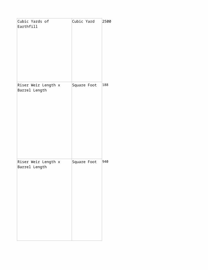
Linear Foot 2500
Pound 1000
Pound 1000
Pound 1800

Pound 4600
Foot 2000
Cubic Yard 1406
Cubic Yard 685
Gallon 250
Gallon 800

Gallon 1100
Gallon 6000
Each 1
Gallon 500
Gallon 9400
Linear Foot 500
Linear Foot 500
Linear Foot 500

Linear Foot 500
Linear Foot 500
Linear Foot 500
Linear Foot 500
Linear Foot 500
Each 1
Each 1
Cubic Foot 10125

Cubic Foot 35060
Cubic Foot 1800
Square Foot 5000
Gallon 1000
Gallon 4300
Gallon 8600

Gallon 4300
Gallon 8600
Square Foot 1200
Square Foot 1200

Square Foot 1200
Square Foot 1200
Gallon 1000
Feet 300

Feet 80
Feet 150

Feet 300
Feet 1000

Foot 500

Feet 1000
Foot 300
Each 1
Each 1
Each 1

Ton-Mile 360
Gallon 1000000
Each 1
Acre 1
Acre 1
Acre 1

Acre 1
Acre 1
Acre 1
Square Yard 500
Square Yard 53

Cubic Yard 1541
Cubic Yard 700
Linear Foot 100
Linear Foot 330

Linear Foot 330
Linear Foot 700
Linear Foot 700
Each 1
Each 1
Each 1

Square Foot 2000
Acre 0.25
Acre 1
Gallon 3000
Cubic Yard 10000
Square Foot 435

Gallon 4700

Practice Name Component
380 - Windbreak/Shelterbelt Est. 1
380 - Windbreak/Shelterbelt Est. 2
380 - Windbreak/Shelterbelt Est. 3
380 - Windbreak/Shelterbelt Est. 4
380 - Windbreak/Shelterbelt Est. 5
380 - Windbreak/Shelterbelt Est. 6
380 - Windbreak/Shelterbelt Est. 7
380 - Windbreak/Shelterbelt Est. 8
380 - Windbreak/Shelterbelt Est. 9
Scenario Number
1 row windbreak, shrubs, hand planted
1 row windbreak, trees, hand planted
2-row windbreak, shrubs, machine planted
2-row windbreak, trees, machine planted
2-row windbreak, trees, machine planted
3 or more row windbreak, shrub, machine planted
3 or more tree rows machine planted windbreak
3 or more row windbreak, trees, machine planted
Per plant 3 or more rows machine planted windbreak

383 - Fuel Break 7 Structure
383 - Fuel Break 8 Forested
384 - Woody Residue Treatment 1
384 - Woody Residue Treatment 2 Chipping and hauling off-site
384 - Woody Residue Treatment 3 Pile and Burn
391 - Riparian Forest Buffer 5 Small container, hand planted
394 - Firebreak 1 Constructed - Light Equipment
394 - Firebreak 2
Woody residue/silvicultural slash treatment- light
Constructed - Medium equipment, flat-medium slopes

394 - Firebreak 3
394 - Firebreak 4 Vegetated permanent firebreak
394 - Firebreak 5
472 - Access Control 1 Trails/Roads Access Control
472 - Access Control 2
472 - Access Control 3 Forest/Farm Access Control
472 - Access Control 5 Deferred Grazing
490 - Tree & Shrub Site Preparation 1 Mechanical, Heavy
490 - Tree & Shrub Site Preparation 2 Mechanical, Light
490 - Tree & Shrub Site Preparation 3 Chemical, Ground Application
Constructed - Medium equipment, steep slopes
Constructed - Wide, bladed or disked firebreak
Animal exclusion from sensitive areas

490 - Tree & Shrub Site Preparation 4 Chemical, Aerial Application
612 - Tree & Shrub Establishment 1 Individual tree - hand planting
612 - Tree & Shrub Establishment 13
612 - Tree & Shrub Establishment 14
650 - Windbreak/Shelterbelt Renovation 1 Sod Release
650 - Windbreak/Shelterbelt Renovation 2 Thinning
650 - Windbreak/Shelterbelt Renovation 3 Pruning
650 - Windbreak/Shelterbelt Renovation 4
650 - Windbreak/Shelterbelt Renovation 5
650 - Windbreak/Shelterbelt Renovation 7 Supplemental Planting-Container
Individual tree - hand planting - moderate protection
Individual tree - hand planting - high protection
Tree/Shrub Removal with Chain Saw
Removal <8 inches DBH with Skidsteer

650 - Windbreak/Shelterbelt Renovation 8
650 - Windbreak/Shelterbelt Renovation 8 Supplemental Plantings-Bare Root
650 - Windbreak/Shelterbelt Renovation 9 Coppicing
660 - Tree Pruning 1 Pruning-Fire Hazard
660 - Tree Pruning 2 Pruning-White Pine Blister Rust
666 - Forest Stand Improvement 1
666 - Forest Stand Improvement 2
666 - Forest Stand Improvement 3
666 - Forest Stand Improvement 4
666 - Forest Stand Improvement 5 Aspen Regeneration
Removal > 8 inches DBH with Dozer
Non-Commercial Thinning, Mastication
Pre-Commercial Thinning, High Intensity
Pre-Commercial Thinning, Medium Intensity
Pre-Commercial Thinning, Low Intensity

Scenario Description
Single row of shrubs for wind protection, wildlife habitat, or snow management. Shrubs planted by hand 4 feet apart. This practice is typically applied to crop, pasture or range lands.
Single foot row of conifer tree seedlings for wind protection, wildlife habitat, or snow management. Trees planted by hand 10 feet apart. This practice is typically applied to crop, pasture or range lands.
Two rows of shrubs for wind protection, energy conservation, wildlife habitat, air quality, snow management or to provide a visual screen. Shrubs planted with a tree planting machine 4 feet apart in the row with rows 16 feet apart. This practice is typically applied to crop, pasture or range lands.
Two rows of hardwood trees for wind protection, energy conservation, wildlife habitat, air quality, snow management or to provide a visual screen. Trees planted with a tree planting machine 10 feet apart in the row with rows 16 feet apart. Herbivores (deer, rabbits, etc.) are NOT expected to browse tree seedlings, tree protection is not needed. This practice is typically applied to crop, pasture or range lands.
Two rows of hardwood tree seedlings for wind protection, energy conservation, wildlife habitat, air quality, snow management or to provide a visual screen. Trees planted with a tree planting machine 10 feet apart in the row with rows 16 feet apart. Herbivore (deer, rabbits, etc.) damage is likely, so each tree must be protected with a rigid tube tree shelter. This practice is typically applied to crop, pasture or range lands.
Three or more rows of shrubs for wind protection, energy conservation, wildlife habitat, air quality, snow management. Shrubs planted with a tree planting machine, 4 feet apart in the row with rows 16 feet apart. This practice is typically applied to crop, pasture or range lands.
Three or more rows of trees for wind protection, energy conservation, wildlife habitat, air quality, snow management or to provide a visual screen. The outside rows are conifers the inside row(s) are hardwoods. Trees 10 feet apart with rows 16 feet apart, planted with a tree planting machine. Herbivores are not expected to browse planted seedlings, so tree shelters are not needed. This practice is typically applied to crop, pasture or range lands.
Typically three or more 500 foot rows of trees and/or shrubs for wind protection, energy conservation, wildlife habitat, air quality, snow management or to provide a visual screen. Trees or shrubs are typically planted with a tree planting machine 10 feet apart in the row with rows 16 feet apart. If herbivore (deer, rabbits, etc.) damage is possible, plantings can be protected with a rigid tube tree shelter or other applicable protection measure. This practice is typically applied to crop, pasture or range lands.
Three or more rows of trees for wind protection, energy conservation, wildlife habitat, air quality, snow management or to provide a visual screen. The outside rows are shrubs and inner row(s) are conifers and hardwoods. Trees 10 feet apart with rows 20 feet apart, planted with a tree planting machine. Control competing vegetation. Herbivores are not expected to browse planted seedlings, so tree shelters are not needed. This practice is typically applied to crop, pasture or range lands.

Fuel Break installation requires intensive overstory thinning, pruning, understory management and slash treatment around a structure/home. Overstory thinning is done by hand or mechanical methods. Dead fuels are removed from the overstory. Pruning and understory management are done by hand. Slash treatment is done by hand or by mechanical methods.
Fuel Break installation requires: Overstory thinning; Limited pruning and understory management; Extensive slash treatment. Apply fuel break at property boundaries, along roads or other key locations to reduce continuity of vegetation cover, and as a further extention of treatment around a structure/home. Overstory thinning is done by hand or mechanical methods. Dead fuels are removed from the overstory. Pruning and understory management are done by hand. Slash treatment is done by hand or by mechanical methods.
Treating an area of forest slash to reduce hazardous fuels and the risk of insect and disease, improve organic matter and reduce erosion while improving water quality. Slash is treated with both hand (cutting, lopping, etc.) and mechanically (masticating, chipping, etc.). Typically done by hand and light equipment.
Reducing woody waste created during forestry, agroforestry and horticultural activities by gathering, chipping, and hauling off site to achieve management objectives. Does not include transport from property to a commercial facility.
Treating the forest slash generated from a forest management activity to: Reduce hazardous fuels; Reduce the risk of insect and disease; Improve wildlife habitat. Slash is to be piled and burned in small piles made by hand or mechanical methods. Piles will be in forest openings and away from nearby trees so not to impact them when the piles are burnt. Slash will be burnt when the conditions are safe for burning. Mechanical methods include a brush rake on a both heavy and light equipment. Hand work with chainsaws are used on steep slopes.
Establish a buffer of trees and/or shrubs into a suitably prepared site to restore riparian plant communities and associated benefits. The buffer will be located adjacent to and up-gradient from a watercourse or water body extending a minimum of 35 feet wide. The planting will consist of hand planted small containerized shrubs, evergreen, and deciduous trees. One third of the area will be planted to each woody plant type. Planting for shrubs will be done at 6' x 6' spacing, evergreen tree spacing will be 12' x 15' and deciduous tree spacing at 15' x 15'. Tree shelters wil be placed on the hardwoods and evergreens.
Installation of a bare-ground firebreak of a minimum width of 15' around a 20 acre field/farm using farm equipment (2 passes). Generally water control devices such as water bars are not needed due either to the lack of steep terrain or the temporary nature of the firebreak.
Use of medium equipment such as small dozers to blade, disk, plow, etc. bare-soil firebreaks on slopes less than 15%. Generally, water control devices such as water bars are limited to 10 or less per 1,000 feet when properly planned and installed using the same equipment.

Restricting human access to a field/farm/property through use of signage and other markings.
Use of equipment such as small dozers to blade bare-soil firebreaks on slopes greater than 15%. Water control devices such as water bars placed at approximately 15 to 25 per 1,000 ft section of firebreak, are necessary to control erosion. These will be installed with the same equipment.
Establishing a 20 foot wide strip of permanent vegetation that will serve as a green firebreak. Scenario includes clearing the site, preparing the seedbed, seeding (typically cool season grasses and/or legumes), and applying needed soil amendments. Clearing will be achieved with the use of a bush hog or similar equipment. Seedbed preparation and vegetation establishment will be accomplished with farm equipment. Soil amendments will be applied according to local FOTG guidance. This scenario does not include follow-up maintenance operations such as weed control. mowing, etc.
Installing a bare-ground firebreak with a width of 30' or more on gently to strongly sloping slopes with equipment such as a dozer with a heavy disk. Using smaller equipment, erosion control devices such as water bars will be installed at approximately 15 to 25 per 1,000 feet of firebreak length. Devices will have stable outlets.
Restricting access to the use of forest/farm roads and trails by the use of a gate and limited fencing. Resource concerns include Undesirable plant productivity and health, Concentrated flow erosion, Soil compaction, Excessive sediment in surface waters, and Wildlife habitat degradation.
Excluding animals from an area in order to address identified resource concerns. This is for facilitating exclusion of animals to protect or enhance natural resource values. Control will be by temporary electric fencing. Any need for permanent fencing will be planned and installed using the Fence practice (382). Clearing of brush and trees is not necessary. Resource concerns include Wildlife Habitat degradation, Undesirable plant productivity and health, and/or Excessive sediment in surface waters.
Temporarily excluding livestock from an area in order to address resource concerns. Deferred grazing for one, two or three growing seasons to protect and hence plant health. For special use situations such as after a natural disaster (fire, flood, etc.). Use existing fencing.
This practice involves the use of heavy machinery to treat an area in order to improve site conditions for establishing trees and/or shrubs. Typical sites include trees and brush cover that is not appropriate to the site or providing the desired condition for the landowner.
This practice involves the use of light/moderate machinery to clear above ground vegetation and to also rip/cut/lift underground root systems in order to improve site conditions for establishing trees and/or shrubs. Typical sites include abandoned fields, pastures, rangelands, agricultural fields or forestlands that have been harvested.
This practice involves the use of various herbicides applied using ground-based machinery (and some hack-n-squirt treatment of select trees) in order to remove undesirable vegetation and improve site conditions for establishing trees and/or shrubs. Typical sites include abandoned fields, pastures, rangelands, agricultural fields or forestland that was recently harvested.

This practice involves the use of herbicides applied by helicoptor in order to remove undesirable vegetation and improve site conditions for establishing trees and/or shrubs. This typical scenraio includes open land such as abandoned fields, pastures or forestlands that were recently harvested.
Tree seedlings will be hand planted in the forested area where few or no forest trees are growing, the existing stand of trees needs underplanting, or the previously planted seedling tree stocking level is below desirable conditions. Wildlife habitat is degraded by loss of forest conditions.
Tree seedlings will be hand planted in forested areas in order to establish desired stocking levels of the preferred tree species for the site. The typical planted tree is treated with chemical spot treatment and alternative browse protection (non-tube, for example Plantskydd), or other similar combination of protection. Wildlife habitat is degraded by loss of forest conditions.
Tree seedlings will be hand planted in forested areas in order to establish desired stocking levels of the preferred tree species for the site. The typical planted tree is treated with chemical spot treatment, protective tube animal control device, and in high browse areas additional alternative browse protection (for example Plantskydd), or other similar combination of protection. Wildlife habitat is degraded by loss of forest conditions.
Reduce competition from sod around trees/shrubs within a windbreak/shelterbelt. Apply appropriate herbicide to stress or kill competing sod vegetation between and/or within tree/shrub row. A herbicide application is completed to significantly reduce competition from sod (grass) in the windbreak.
Windbreak is thinned by hand w/chainsaw and cut stumps have herbicide applied to prevent undesirable sprouting.
Windbreak is pruned by hand (hand tools + chainsaw) to improve shape and form of trees and/or shrubs so that the overall effectiveness of the windbreak will improve. Slash is treated to prevent potential insect, disease, fire and operability problems.
Windbreak renovation requires the removal of degraded or inappropriate trees or shrubs within a windbreak. This may include removal of entire rows, including stumps or roots, or selected trees/shrubs in order to prepare for the necessary planting of a replacement row within the windbreak, improve the health of the remaining rows, and/or allow for supplemental planting to expand the windbreak.
Windbreak renovation requires the removal of degraded or inappropriate trees or shrubs within a windbreak. This may include removal of entire rows, including stumps or roots, or selected trees/shrubs in order to prepare for the necessary planting of a replacement row within the windbreak, improve the health of the remaining rows, and/or allow for supplemental planting to expand the windbreak.
Parts of the windbreak being renovated have died. Supplemental plantings of containerized trees/shrubs will improve the effectiveness and longevity of the windbreak.

Stands are treated mechanically by a variety of machines that remove target trees by grinding.
Windbreak renovation requires the removal of degraded or inappropriate trees or shrubs within a windbreak. This may include removal of entire rows, including stumps or roots, or selected trees/shrubs in order to prepare for the necessary planting of a replacement row within the windbreak, improve the health of the remaining rows, and/or allow for supplemental planting to expand the windbreak.
Parts of the windbreak being renovated have died. Supplemental plantings of bare root trees/shrubs will improve the effectiveness and longevity of the windbreak.
Coppicing of selected trees and understory vegetation in a windbreak/shelterbelt is needed to ensure that species composition and stand structure continue to serve their intended purpose.
Pruning the lower branches of trees in order to reduce ladder fuels and increase the height to the base of the crown in a forest stand where the risk of wildfires is elevated. Hand tools and power tools are used to cut branches from trees on the outside of the branch collar.
Prune the lower branches of western white pine in order to eliminate the threat of blister rust infestation. Hand tools and power tools are used to cut branches from trees on the outside of the branch collar.
Thinning in overstocked forest stands which are generally on extremely steep slopes or have large numbers of live trees in the pre-treatment stand (often in excess of 3,500 trees per acre). Trees that are cut in the thinning often hang up in the canopy of the residual stand and must be pulled or cut into smaller segments in order to lay them on the ground. Stands are treated by crews with chainsaws.
Thinning in overstocked forest stands which will commonly occur on moderately steep to steep slopes or have about 1,500 to 3,000 live trees per acre in the pre-treatment stand. Stands are treated by crews with chainsaws.
Thinning in overstocked forest stands which typically occur on flatter slopes or have low numbers of live trees in the treatment stand (1,000 or less trees per acre). Cut trees usually fall unimpeded from the canopy and drop to the ground. Stands are treated by crews with chainsaws.
Existing stands are treated either mechanically or by crews with chainsaws to eliminate existing conifers and over-mature aspen.

Scenario Measurement
Foot 500
Foot 500
Foot 500
Foot 500
Foot 500
Foot 500
Foot 500
Foot 500
Each 100
Scenario Unit
Scenario TypicalSize
length of windbreak row(s)
length of windbreak row(s)
length of windbreak row(s)
length of windbreak row(s)
length of windbreak row(s)
length of windbreak row(s)
length of windbreak row(s)
length of windbreak row(s)
length of windbreak row(s)

Acre 4
Acre 10
Acres treated Acres 40
Acres treated Acres 10
Acre 10
Area of planting Acre 3
Length of firebreak Feet 4000
Length of firebreak Feet 3000

Length of firebreak Feet 1000
Length of firebreak Feet 3000
Length of firebreak Feet 1000
Number Each 1
Length of fence Feet 3600
Feet 3500
Size of grazing unit Acre 100
Area of Treatment Acre 40
Area of Treatment Acre 20
Area of Treatment Acre 40

Area of Treatment Acre 40
Area Planted Each 6000
Area Planted Each 6000
Area Planted Each 6000
Length of Renovation 5000
Length of Renovation 1100
Length of Renovation 1100
Length of Renovation 1000
Length of Renovation 1000
Area of Renovation Each 118
Linear Feet
Linear Feet
Linear Feet
Linear Feet
Linear Feet

Length of Renovation 1000
Area of Renovation Each 95
Area of Renovation 1200
area of treatment Acre 10
area of treatment Acre 10
Acres treated Acres 25
Acres treated Acre 30
Area treated Acre 30
Area Treated Acre 30
Area treated Acre 5
Linear Feet
Linear Foot

Practice Name Component
314 - Brush Management 1 Mechanical, Hand tools
314 - Brush Management 2 Mechanical Light Equipment
314 - Brush Management 3
314 - Brush Management 4 Mechanical and Chemical
314 - Brush Management 5
314 - Brush Management 6 Chemical - Ground Applied
314 - Brush Management 7 Chemical, Aerial Fixed Wing
315 - Herbaceous Weed Control 1
315 - Herbaceous Weed Control 2 Mechanical, Hand
315 - Herbaceous Weed Control 3 Mechanical
Scenario Number
Mechanical, Large Shrubs, Medium Infestation
Mechanical & Chemical, Cut stump plus chemical treatment, pile & burn, chip, etc
Biological Control - Targeted Grazing

315 - Herbaceous Weed Control 4 Chemical, Spot
315 - Herbaceous Weed Control 5 Chemical, Ground
315 - Herbaceous Weed Control 6 Chemical, Aerial
315 - Herbaceous Weed Control 7 Biological - Insects
338 - Prescribed Burning 1 Understory Burn
338 - Prescribed Burning 2 Site Preparation
338 - Prescribed Burning 3 Pile Burning
338 - Prescribed Burning 4
338 - Prescribed Burning 5
Level Terrain, Herbaceous Fuel < 640 ac.
Level Terrain - Herbaceous Fuel >640 ac.

338 - Prescribed Burning 6
338 - Prescribed Burning 7
338 - Prescribed Burning 8
338 - Prescribed Burning 9
382 - Fence 1 Barbed/Smooth Wire
382 - Fence 2 Wire Difficult
382 - Fence 3 Woven Wire
382 - Fence 4 Electric
382 - Fence 5 Confinement
Level Terrain, Volatile fuels < 4 ft tall, <640 ac
Level Terrain, Volatile fuels < 4 ft tall, >640 ac
Level Terrain, Volatile fuels > 4 ft tall, <640 ac
Level Terrain, Volatile fuels > 4 ft tall, >640 ac

382 - Fence 6 Safety
382 - Fence 7 Wildlife Exclusion
382 - Fence 8 Livestock Protection
511 - Forage Harvest Management 1 Improved Forage Quality
511 - Forage Harvest Management 2 Organic Preemptive Harvest
511 - Forage Harvest Management 4
512 - Forage and Biomass Planting 1
512 - Forage and Biomass Planting 2 Pollinator Friendly
528 - Prescribed Grazing 1 Range Standard
528 - Prescribed Grazing 2 Range Intensive
528 - Prescribed Grazing 3 Habitat Mgt. Standard
Perennial Crop - Directed Mowing
Seedbed Prep. Seed & Seeding- Introduced Perennial Cool Season Grasses with legume

528 - Prescribed Grazing 4 Habitat Mgmt, Rest Rotation
528 - Prescribed Grazing 5 Pasture Intensive
550 - Range Planting 1 Native, Standard Preparation
550 - Range Planting 2 Native, Heavy Preparation
550 - Range Planting 3 Native, Wildlife or Pollinator

Scenario Description
Using hand tools, such as axes, shovels, hoes, nippers, brush pullers, and including chainsaws to remove or cut off woody plants at of below the root collar. Typical area is moderate rolling to gentle sloping, moderately deep to deep soils that have stands of woody and non herbaceous species that are in the early phases of invasions.
Removal of small woody vegetation on gentle sloping to moderately deep to deep soils. The practice entails the removal of brush by the use of mechanical cutter, chopper or other light equipment in order to reduce fuel loading and improve ecological site condition. Brush density has exceeded desired levels based on ecological site potential.
Removal of large woody vegetation of on gentle sloping to moderately deep to deep soils. The practice entails the removal of brush by pushing, grubbing, masticating, chaining and then raking or piling in order to reduce fuel loading and improve ecological site condition. Brush density has exceeded desired levels based on ecological site potential.
Removal of small sprouting woody vegetation on gentle sloping to moderately deep to deep soils. The practice entails the removal of brush by the use of mechanical cutter, chopper or other light equipment followed by an application of low cost chemicals in order to reduce fuel loading and improve ecological site condition. Brush density has exceeded desired levels based on ecological site potential.
Removal of Russian olive and/or Salt Cedar from riparian areas and drainage ways on moderately deep to deep soils. The practice entails the removal of Russian olive/Salt Cedar by the use of mechanical cutter, chopper, masticator or other light equipment or sawyer followed by an application of approved chemicals (Remedy, Garlon, etc) at approprite rates on the exposed cut stump to eliminate sprouting. Cut material will then be piled and burned when dry, chipped and scattered or hauled off site.
Brush management performed on rangeland, grazed forest, or pasture thru the use of broadcast application of low cost chemical(s) to reduce or remove undesirable shrub species in uplands and other areas not in or directly adjacent to streams, ponds, or wetlands.
Brush management performed on rangeland, grazed forest, or pasture thru the use of broadcast aerial application of chemical(s) to reduce or remove undesirable shrub species in uplands and other areas not in or directly adjacent to streams, ponds, or wetlands.
Management of invasive, noxious, or prohibited plant species through the use of targeted livestock grazing practices. Goats, sheep, or cattle are closely herded to concentrate grazing impacts on undesirable herbaceous species. Typical area is level to gently sloping on moderately deep to deep soils and may include both upland and lowland sites.
Using hand tools, such as axes, shovels, hoes, nippers, to remove or cut off noxious or invasive herbaceous plants at or below the root collar. Typical area is level to gentle sloping, moderately deep to deep soils that have noxious or invasive herbaceous species that are in the early phases of invasions.
Removal of noxious or invasive herbaceous species on gentle sloping to moderately deep to deep soils. The practice entails the removal of noxious or invasive herbaceous species using a mower, brush hog, disc or other light equipment in order to reduce fuel loading, improve ecological condition, and improve wildlife habitat values.

Land unit on which invasive species control would be beneficial in order to improve the ecological condition, and forage conditions for domestic livestock or wildlife. The practice entails the control of noxious or invasive herbaceous vegetation using hand-carried equipment (such as a backpack and hand-sprayer) to apply chemicals.
Land unit on which invasive species control would be beneficial in order to improve the ecological condition, and forage conditions for domestic livestock or wildlife. The practice entails the control of noxious or invasive herbaceous vegetation using ground equipment to apply chemicals.
Land unit on which invasive species control (primarily annual grasses) would be beneficial in order to improve the ecological condition, and forage conditions for domestic livestock or wildlife. The practice entails the control of noxious or invasive herbaceous vegetation by use of chemical treatment using airplane or helicopter.
Management of invasive, noxious, or prohibited plant species through the establishment of populations of species specific biological control insect agents released into the target plant population, or the collection and transfer of agents from one unit to another. Typical area is open rangeland or pasture, level to steeply sloping, on shallow to deep soils, and may include both upland and lowland sites.
Applying a prescribed burn according to designed burn plan and NRCS Prescribed Burning (338) standard and specifications. An Understory burn can consume debris or leaf litter under controlled conditions that otherwise could burn uncontrollably and devastatingly. Prior to burning unit may need to be treated to reduce slash height and quantities. Burn should be cool enough to not cause mortality to residual stand but also must reduce litter and debris.
Treating areas to encourage natural seeding or to permit reforestation by planting or direct seeding. Burning is utilized to eliminate existing competition and debris, reduce forest fuel and to prepare the site for planting or seeding. Burning a cutover site helps prepare the site for replanting. Burn should expose a portions of bare soil for planting. Objectives of a site preparation burn may dictate timing and burn intensity.
Burning pile of woody debris derived from mechanical brush management application. Unit is based on no more than three piles actively burning per individual. Piles are 12'X12'X12' and ignited separately. 10 piles burned/day/individual.
Applying a prescribed burn according to designed burn plan and NRCS Prescribed Burning (338) standard and specifications in order to control undesirable species, improve wildlife habitat, improve plant productivity and/or quality, facilitate grazing distribution and maintain ecological processes. This scenario is based on a burn area of less than 640 acres and applies under the following conditions: where the terrain of the majority of the area to be burned <15% slopes with herbaceous and/or low volatile woody fuel with no high volatile fuels.
Applying a prescribed burn according to designed burn plan and NRCS Prescribed Burning (338) standard and specifications in order to control undesirable species, improve wildlife habitat, improve plant productivity and/or quality, facilitate grazing distribution and maintain ecological processes. This scenario is based on a burn area of greater than 640 acres and applies under the following conditions: where the terrain of the majority of the area to be burned <15% slopes with herbaceous and/or low volatile woody fuel with no high volatile fuels.

Applying a prescribed burn according to designed burn plan and NRCS Prescribed Burning (338) standard and specifications in order to control undesirable species, improve wildlife habitat, improve plant productivity and/or quality, facilitate grazing distribution and maintain ecological processes. This scenario is based on a burn area of less than 640 acres and applies under the following conditions: where the terrain of the majority of the area to be burned <15% slopes with herbaceous and low volatile woody fuel with high volatile woody fuels less than 4ft tall.
Applying a prescribed burn according to designed burn plan and NRCS Prescribed Burning (338) standard and specifications in order to control undesirable species, improve wildlife habitat, improve plant productivity and/or quality, facilitate grazing distribution and maintain ecological processes. This scenario is based on a burn area of greater than 640 acres and applies under the following conditions: where the terrain of the majority of the area to be burned <15% slopes with herbaceous and low volatile woody fuel with high volatile woody fuels less than 4ft tall.
Applying a prescribed burn according to designed burn plan and NRCS Prescribed Burning (338) standard and specifications in order to control undesirable species, improve wildlife habitat, improve plant productivity and/or quality, facilitate grazing distribution and maintain ecological processes. This scenario is based on a burn area of less than 640 acres and applies under the following conditions: where the terrain of the majority of the area to be burned <15% slopes with herbaceous and low volatile woody fuel with high volatile woody fuels greater than 4ft tall, but fire is still a ground fire carried by fine fuel.
Applying a prescribed burn according to designed burn plan and NRCS Prescribed Burning (338) standard and specifications in order to control undesirable species, improve wildlife habitat, improve plant productivity and/or quality, facilitate grazing distribution and maintain ecological processes. This scenario is based on a burn area of greater than 640 acres and applies under the following conditions: where the terrain of the majority of the area to be burned <15% slopes with herbaceous and low volatile woody fuel with high volatile woody fuels greater than 4ft tall, but fire is still a ground fire carried by fine fuel.
Multi-strand, Barbed or Smooth Wire - Installation of fence will allow for implementation of grazing management that allows for an adequate rest and recovery period, protection of sensitive area, improved water quality, reduction of noxious and invasive weeds.
Barbed, Smooth ,or Woven Wire Difficult Installation - Installation of fence in difficult situations will allow for implementation of grazing management that allows for an adequate rest and recovery period, protection of sensitive area, improved water quality, reduction of noxious and invasive weeds.
Woven - Installation of fence will allow for implementation of a grazing management that allows for an adequate rest and recovery period, protection of sensitive area, improved water quality, reduction of noxious and invasive weeds. Woven wire is typically used in applications with sheep, goats, hogs, wildlife exclusion, shelterbelt/tree protection, etc.
Electric - Installation of fence will allow for implementation of a grazing management that allows for an adequate rest and recovery period, protection of sensitive area, improved water quality, reduction of noxious and invasive weeds.
Installation of confinement fence is needed to addresses resource concerns associated with livestock feeding operations. Provide protection of sensitive areas, improve water quality, reduction of noxious and invasive weeds.

A barrier (fence) implemented on an NRCS constructed waste storage system according to engineering design to exclude human access. Permanently installed fence built to keep humans and livestock away from waste ponds & lagoons Heavy grade fence materials and close post spacing required.
Installation of fence reduces resource concerns associated with livestock/wildlife interactions and/or wildlife access to prevent conflicts between humans and livestock or wildlife species.
Installation of electrified fladry (also called turbofladry) reduces wolf predation on livestock. Fladry is a barrier system of red flags hanging from fence wire that scares wolves; electrified fladry also incorporates an electric shock designed to decrease the potential for wolves to habituate to the barriers.
Incorporating cultural practices and recordkeeping will result in improved plant health and vigor in addition to improved forage quality and livestock performance. Forage stand longevity and sustainability will also increase.
Preemptive harvest of forage crops to prevent damage from insects (such as leafhopper on alfalfa) or other pests results in better forage quality and better livestock performance.
In perennial forage crops, the harvesting of forage to promote the reproduction of ground nesting birds. Leaving blocks of unharvested forage crops for nesting or winter cover will benefit ground nesting birds; The selected fields should be large enough to promote ground nesting birds. After young have fledged the field will be left standing for winter cover.
Establish or reseed adapted perennial grasses and legumes to improve or maintain livestock/wildlife nutrition and health, extend the length of the grazing season, and provide soil cover to reduce erosion. Used for either conventional or no-till seeding of perennial cool season grasses for pasture, hayland, and wildlife openings. This practice may be utilized for organic or regular production. This scenario assumes seed, equipment and labor for seed bed prep, tillage, seeding ,and spreading.
Establishment of a mixture of adapted perennial species on a pasture or rangeland unit to improve wildlife habitat, benefit pollinators & beneficial insects, improve forage condition, and/or reduce erosion. Seed mix of predominately native species that benefit pollinators and wildlife species which includes a minimum of 3 flowering plants which could be forb, legume or shrub and 1 perennial based on range conditions and availability of seed. For pollinators consideration is given to selecting plants that bloom sequentially throughout the growing season.
Design and implementation of a grazing system through multiple units that will enhance rangeland health and ecosystem function as well as optimize efficiency and economic return through monitoring (ex:photo points, stubble height after grazing, etc) & record keeping.
Design and implementation of a grazing system consisting of 6 or more grazing units (pastures) per herd that will enhance rangeland health and ecosystem function by providing adequate rest and recovery times as well as optimize efficiency and economic return through monitoring (ex: trend, composition, production, etc), record keeping.
Development and implementation of a grazing schedule that will enhance habitat components for the identified wildlife species of concern.

Development and implementation of a grazing schedule that will enhance habitat components for the identified wildlife species of concern. The planned rest period includes two full nesting seasons for a minimum of 20% of identified habitat acres. For example rest period begins on April 1st, 2013 and extends through June 15th, 2014.
Design and implementation of a grazing system with multiple paddocks with livestock rotated at least every three days that will enhance pasture condition and ecosystem function as well as optimize efficiency and economic return through monitoring (ex: trend, composition, production, etc), record keeping.
Establishment of a mixture of adapted perennial species on cropland, pasture or degraded rangeland to improve forage condition, improve wildlife habitat and/or reduce erosion. Seed mix of Native species is chosen based on range conditions and availability of seed. Planting by preparing a seedbed with a LIGHT TO MODERATE TILLAGE (ex: ripping or heavy disk) and seeding with no-till drill, range drill, or broadcasting. Use of a cover crop is optional.
Establishment of a mixture of adapted perennial species on a cropland, pasture and degraded rangeland unit to improve forage condition, improve wildlife habitat and/or reduce erosion. Seed mix of Native species is chosen based on range conditions and availability of seed. Planting by preparing a seedbed with MODERATE TO HEAVY TILLAGE (ex: ripping & heavy disk) and seeding with a cover crop, no-till drill, range drill, or broadcasting.
Establishment of a mixture of Native perennial species on a pasture or rangeland unit to improve wildlife habitat, benefit pollinators & beneficial insects, improve forage condition, and/or reduce erosion. Seed mix of predominately native species that benefit pollinators and wildlife species which includes a minimum of 3 flowering plants which could be forb, legume or shrub and 1 perennial based on range conditions and availability of seed. For pollinators consideration is given to selecting plants that bloom sequentially throughout the growing season.

Acres treated Acre 80
Acres planned Acre 200
Acres planned Acre 120
Acres planned Acre 200
Acres planned Acre 30
Acres planned Acre 160
Acres planned Acre 1000
Acres teated Acre 10
Acres treated Acre 10
Acres treated Acre 40
Scenario Measurement
Scenario Unit
Scenario TypicalSize

Acres treated Acre 20
Acres treated Acre 20
Acres treated Acre 160
Acre 10
Acres planned Acre 320
Acres planned Acre 80
Each 10
Acres planned Acre 120
Acres planned Acre 700
Number of piles burned

Acres planned Acre 120
Acres planned Acre 700
Acres planned Acre 120
Acres planned Acre 700
Length of Fence Foot 2640
Length of Fence Foot 2640
Length of Fence Foot 2640
Length of Fence Foot 1320
Length of Fence Foot 700

Length of Fence Foot 550
Length of Fence Foot 1320
Length of fence Foot 1300
Acre 30
Acre 30
Acre 30
Acre 100
Acre 10
Acre 1000
Acre 1000
Acre 1000
Improved Relative Feed Value
Relative Feed Value Maintained
Increased grassland bird populations.
Acres of Forgage and Biomass Planting

Acre 1000
Acre 160
Acres of Range Planting Acre 80
Acres of Range Planting Acre 80
Acres of Range Planting Acre 20

Practice Name Component
390 - Riparian Herbaceous Cover 1 Aquatic Wildlife
390 - Riparian Herbaceous Cover 2 Plugging and Seeding
Scenario Number

390 - Riparian Herbaceous Cover 3
395 - Stream Habitat Improvement 1
395 - Stream Habitat Improvement 2
Cool Season Grasses w/ Forbs
Riparian Zone Improvement-Forested
Instream wood placement

395 - Stream Habitat Improvement 3
395 - Stream Habitat Improvement 4
Instream rock placement
Rock and wood structures

395 - Stream Habitat Improvement 5 Fish Barrier
396 - Aquatic Organism Passage 1 Concrete Dam Removal

396 - Aquatic Organism Passage 2 Earthen Dam Removal

396 - Aquatic Organism Passage 3 Blockage Removal

396 - Aquatic Organism Passage 4 Nature-Like Fishway

396 - Aquatic Organism Passage 5 CMP Culvert

396 - Aquatic Organism Passage 6 Bottomless Culvert

396 - Aquatic Organism Passage 7 Concrete Box Culvert

396 - Aquatic Organism Passage 8 Bridge

396 - Aquatic Organism Passage 9 Concrete Ladder

396 - Aquatic Organism Passage 10 Complex Denil

396 - Aquatic Organism Passage 11 Alaskan Steeppass

396 - Aquatic Organism Passage 12 Low Water Crossing

396 - Aquatic Organism Passage 13 Paddlewheel Screen

396 - Aquatic Organism Passage 14 Rotating Drum Screen
422 - Hedgerow Planting 1 Pollinator Habitat
422 - Hedgerow Planting 2 Contour

422 - Hedgerow Planting 3 Wildlife machine plant
422 - Hedgerow Planting 4 Wildlife Cool Season
644 - Wetland Wildlife Management 1 Nesting Structures

644 - Wetland Wildlife Management 2
644 - Wetland Wildlife Management 3
645 - Upland Wildlife Habitat Management 1 Lek Monitoring
645 - Upland Wildlife Habitat Management 2 Annual Food Plot
645 - Upland Wildlife Habitat Management 3
Monitoring & Management - renamed medium intensity scenario and deleted low and high scenarios
Topographic Feature Creation - renamed Topog Feature Creation Low scenario and deleted medium and scenarios
Snag Creation-TreeToppingOrTreeGirdling

1
2
657 - Wetland Restoration 1 Mineral Flat
657 - Wetland Restoration 2
657 - Wetland Restoration 3
646 - Shallow Water Development and Management
Shallow Water Management
646 - Shallow Water Development and Management
Shallow Water Management-High Level
Riverine Levee Removal and Floodplain Features
Depression Sediment Removal and Ditch Plug

657 - Wetland Restoration 4
658 - Wetland Creation 1
659 - Wetland Enhancement 1 Mineral Flat
659 - Wetland Enhancement 2
659 - Wetland Enhancement 3
659 - Wetland Enhancement 4
Riverine Channel and Floodplain Restoration
Wetland Creation, Wildlife Pond
Riverine Levee Removal and Floodplain Features
Depression Sediment Removal and Ditch Plug
Riverine Channel and Floodplain Restoration

734 - Fish and Wildlife Structure 1
734 - Fish and Wildlife Structure 2
734 - Fish and Wildlife Structure 3
734 - Fish and Wildlife Structure 4 Burrowing Owl Burrow
734 - Fish and Wildlife Structure 5 Lunkers
734 - Fish and Wildlife Structure 6 Brush and Rock Piles
734 - Fish and Wildlife Structure 7 Fence Markers
734 - Fish and Wildlife Structure 8
734 - Fish and Wildlife Structure 9 Escape Ramps
Nesting Boxes with pole and predator guard
Nesting Boxes with pole and without predator guard
Nesting and Rearing Box without pole
Wildlife Friendly Fence Retrofit, Wire Only with Fence Markers

Scenario Description
Aquatic Wildlife: This scenario addresses inadequate herbaceous plant community function or diversity within the specific transitional zone between terrestrial and aquatic habitats in rangeland, pasture, cropland, and forest where natural seeding methods and/or management is unlikely to improve the plant community within a reasonable time period. This scenario applies to work not covered under NRCS Conservation Practice Range Planting (528), Forage and Biomass Planting (512), Critical Area Planting (342), Filter Strip (393), Restoration and Management of Rare and Declining Habitats (643), Streambank and Shoreline Protection ( 580), Vegetated Treatment Area (635), Wetland Enhancement ( 659), or Wetland Restoration (657). The typical setting for this scenario is usually a narrow strip between the aquatic and terrestrial habitats subject to intermittant flooding and saturated soils where the exising plant community has been disturbed, destroyed, or the species diversity is unable to provide adequate habitat. Where the establishment of a diverse riparian herbaceous plant community is desired, an adapted mix of grasses, sedges, rushes, and/or forbs tolerant to the site conditions will be planted. Grasses such as tufted hairgrass (Deschampsia cespitosa), sedges, and/or rushes will be planted using plugs. Additional site adapted species of grasses, legumes, and/or forbs may be added by broadcast and/or no-till or range drill seeding methods as necessary to accomplish the intended purpose(s). Where chemical control of undesirable vegetation, including invasives, is required to reduce competition for the desired plant community the Herbaceous Weed Control (315) practice should be used. Seedbed preparation may require LIGHT TILLAGE (disking). WHEN POLLINATOR HABITAT IS A CONSIDERATION: Include 5-10 adapted forb species that bloom sequentially throughout the growing season where feasible.
Plugging: This scenario addresses inadequate herbaceous plant community function or diversity within the specific transitional zone between terrestrial and aquatic habitats in rangeland, pasture, cropland, and forest where natural seeding methods and/or management is unlikely to improve the plant community within a reasonable time period. This scenario applies to work not covered under NRCS Conservation Practice Range Planting (528), Forage and Biomass Planting (512), Critical Area Planting (342), Filter Strip (393), Restoration and Management of Rare and Declining Habitats (643), Streambank and Shoreline Protection ( 580), Vegetated Treatment Area (635), Wetland Enhancement ( 659), or Wetland Restoration (657). The typical setting for this scenario is usually a narrow strip between the aquatic and terrestrial habitats subject to intermittant flooding and saturated soils where the exising plant community has been disturbed, destroyed, or the species diversity is unable to provide adequate habitat. Where the establishment of a diverse riparian herbaceous plant community is desired, an adapted mix of grasses, sedges, rushes, and/or forbs tolerant to the site conditions will be planted. Grasses such as tufted hairgrass (Deschampsia cespitosa), sedges, and/or rushes will be planted using plugs. Where chemical control of undesirable vegetation, including invasives, is required to reduce competition for the desired plant community the Herbaceous Weed Control (315) practice should be used. Seedbed preparation may require LIGHT TILLAGE (disking).

Cool Season Grasses with Forbs: This scenario addresses inadequate herbaceous plant community function or diversity within the specific transitional zone between terrestrial and aquatic habitats in rangeland, pasture, cropland, and forest where natural seeding methods and/or management is unlikely to improve the plant community within a reasonable time period. This scenario applies to work not covered under NRCS Conservation Practice Range Planting (528), Forage and Biomass Planting (512), Critical Area Planting (342), Filter Strip (393), Restoration and Management of Rare and Declining Habitats (643), Streambank and Shoreline Protection ( 580), Vegetated Treatment Area (635), Wetland Enhancement ( 659), or Wetland Restoration (657). The typical setting for this scenario is usually a narrow strip between the aquatic and terrestrial habitats subject to intermittant flooding and saturated soils where the exising plant community has been disturbed, destroyed, or the species diversity is unable to provide proper function and/or adequate habitat. Where the establishment of a diverse riparian herbaceous plant community is desired, an adapted mix of primarily cool season grasses, legumes, and/or forbs tolerant to the site conditions will be planted by broadcast and/or no-till or range drill seeding methods as necessary to accomplish the intended purpose(s). Where chemical control of undesirable vegetation, including invasives, is required to reduce competition for the desired plant community the Herbaceous Weed Control (315) practice should be used. Seedbed preparation may require LIGHT TILLAGE (disking). WHEN POLLINATOR HABITAT IS A CONSIDERATION: Include 5-10 adapted forb species that bloom sequentially throughout the growing season where feasible.
This scenario describes fish and wildlife habitat improvement and/or management actions focused on the community structure and function of forested riparian zone plant communities. The planned activity meets the 395 standard, and facilitating practice standards, especially Codes 390 and 391, utilized in combination to satisfy all requirements specific to habitats needed for the stream and riparian species for which the practice is being implemented. Implementation will improve instream and riparian habitat complexity, water quality, hiding and resting cover, and/or increased food availability for desired riparian and stream species.
This scenario involves placement of large wood (logs, root wads, log structures) into a stream channel in order to improve aquatic habitat that currently does not meet quality criteria for stream species habitat. The Stream Visual Assessment Protocol has documented habitat components lacking for aquatic species (i.e. large wood, pools). A project design for wood placement will be based on assessment of the target stream reach characteristics and those of a suitable reference reach. These characteristics include channel geometry, channel slope, stream bottom substrate size and composition, and the geomorphic setting influencing the channel form, pattern and profile. Large wood and root wads placed into the stream will mimic genus, age, and size of mature trees found in intact, reference riparian areas in the MLRA where the project is located. Large wood/trees with rootwads intact should be placed in streams to create pool habitat according to NRCS engineering specifications and with close review & approval of a fish habitat biologist when possible. Boulders placed to provide ballast shall only be used if the geomorphic setting and project design demand this component. The planned activity will meet the current 395 standard, and facilitating practice standards utilized, and the conservation measures included in any Biological Assessment or Terms and Conditions of any Biological Opinion including timing of work windows required for protected aquatic and riparian species, and protecting/restoring vegetation and substrates of/to areas impacted by heavy equipment. Implementation will result in the improvement of instream habitat complexity, hiding and resting cover, and/or increased food availability for fish and other stream species. Payment for implementation is to defray the costs of project implementation. Monitoring records demonstrating implementation of this scenario will address resource concerns for stream species of concern are required.

This scenario describes the implementation of a stream habitat improvement and management project that places individual boulders or boulder clusters, or rock structures in or adjacent to the stream channel as habitat components. A project design for boulder placement will be based on assessment of the target stream reach characteristics and those of a suitable reference reach. These characteristics include channel geometry, channel slope, stream bottom substrate size and composition, and the geomorphic setting influencing the channel form, pattern and profile. Large rocks/boulders placed in the stream channel will mimic geologic material sizes typically present in the watershed or observed in intact, reference stream reaches in the MLRA where the project is located. Boulders should be placed in streams to create pool habitat and hydraulic complexity according to NRCS engineering specifications and with close review & approval of a fish habitat biologist onsite during implementation of the project design when possible. Spawning gravel placement should be placed to restore spawning area substrates potentially disturbed by rock placement. The planned activity will meet the current 395 standard, and facilitating practice standards utilized. Implementation will result in the improvement of instream habitat complexity, hiding and resting cover, spawning habitat, and/or increased food availability for fish and other stream species. Payment for implementation is to defray the costs of stream habitat assessment, and project implementation. Records demonstrating implementation of this scenario will address resource concerns for stream species of concern will be required.
This scenario describes the implementation of a stream habitat improvement and management project where practices are focused on instream habitat improvement with a combination of rock AND wood structures. This senario involves placement of large wood and rock structures into a stream channel in order to improve aquatic habitat that currently does not meet quality criteria for stream species habitat. The Stream Visual Assessment Protocol has documented habitat components (such as large wood, pools ) are not currently present in the stream or are limited for aquatic species. A project design for placement of habitat structures (boulders, boulder clusters, wood, wood structures) will be based on assessment of (a) the target stream reach characteristics and (b) those of a suitable reference reach. These characteristics include channel geometry, channel slope, stream bottom substrate size and composition, and the geomorphic setting influencing the channel form, pattern and profile. Large rocks/boulders placed in the stream channel will mimic geologic material sizes typically present in the watershed or observed in intact, reference stream reaches in the MLRA where the project is located. Rock boulder sizes should also reflect the geomorphic setting of the stream reach. Large wood placed into the stream under this scenario should be similar in species, age, and size (diameter) as trees found in the surrounding riparian area, to the extent possible. Wood, boulders and/or boulder clusters will be placed in the stream to create pool habitat and hydraulic complexity according to NRCS engineering specifications and with close review & approval of a fish habitat biologist onsite during the planning and implementation of the project if possible. This scenario involves restoring one acre of stream. The planned activity will meet the current 395 standard, and facilitating practice standards utilized. Implementation will result in the improvement of instream habitat complexity, hiding and resting cover, and/or increased food availability for fish and other stream species. Payment for implementation is to defray the costs of project implementation. Records demonstrating implementation of this scenario will address resource concerns for stream species of concern will be required.

This scenario describes the implementation of a stream habitat improvement and management project where practices are focused on the stream channel to intentionally create a barrier to fish passage. The planned activity will meet the current 395 standard, and facilitating practice standards utilized. Implementation will result in protecting native aquatic fauna in the reach from competition or hybridization with non-native fish. This action may also increase food availability for fish and other stream species located above the constructed barrier. Payment for implementation is to defray the costs of stream habitat assessment above the barrier, and project implementation. Records demonstrating implementation of this scenario will address resource concerns for aquatic and riparian species of concern will be required.
Full or partial removal of a concrete or earthen dam to restore aquatic organism passage, improve water quality, and promote functional river ecology and geomorphology. The extent of removal (full or partial) is determined through consultations with the dam owner in consideration of prevailing regulations and site historical status. Adjacent floodplain surfaces above and below the target dam are considered in the planning process to account for shifts in streamflow and geomorphic regime. Resulting channel dimensions and profile are determined on a site-specific basis to reflect--to the fullest extent possible--pre-dam conditions.
Pre-removal sediment assays are completed to determine the toxicity of sediment stored behind the dam. Planning for the reclamation and management of stored sediments is completed according to geomorphic conditions, prevailing regulations, and the results of sediment toxicity investigations. Removal is done with an assortment of equipment, including tracked excavators outfitted with hydraulic chisels, hammers and/or buckets with "thumbs", bull dozers, skid steers, cranes, front-end loaders, and dump trucks. Alternative demolition techniques may include the use of high explosives, diamond-chain, or similar circular saws to remove the dam in a piecewise manner. Removed materials are trucked away and disposed or recycled off-site. Disturbed areas are revegetated with a mix of site-adapted species. Scenario does not include additional measures needed in the active channel and floodplain to account for post-removal changes to stream plan, pattern, or profile, or reclamation of any former impounded areas. Additional structural measures may be necessary to address constructed features associated with the removed dam including canals, raceways, adjacent spillways, navigation locks, access and maintenance roads, or similar civil works.
RESOURCE CONCERNS: INADEQUATE HABITAT FOR FISH AND WILDLIFE –Habitat degradation; EXCESS WATER – Ponding, flooding, seasonal high water table, seeps, and drifted snow; WATER QUALITY DEGRADATION – Elevated water temperature.
Payments for these associated practices are made separately and are covered by other typical scenarios and payment schedules. See relevant CPS for additional information.
---Site Preparation and Reclamation associated with project footprint: (326) Clearing and Snagging, (342) Critical Area Planting, (382) Fence, (390) Riparian Herbaceous Cover, (391) Riparian Forest Buffer, (612) Tree/Shrub Establishment
---Reach Planning/Habitat Enhancement: (395) Stream Habitat Improvement and Management,
---Structural Measures Associated with Scenario but outside of project footprint: (410) Grade Stabilization Structure, (584) Channel Bed Stabilization, (580) Streambank and Shoreline Protection, (587) Structure for Water Control

Full removal of an earthen dam to restore aquatic organism passage, improve water quality, and promote functional river ecology and geomorphology. The removal extent is determined through consultations with the dam owner in consideration of prevailing regulations and site historical status. Adjacent floodplain surfaces above and below the target dam are considered in the planning process to account for shifts in streamflow and geomorphic regime. Resulting channel dimensions and profile are determined on a site-specific basis to reflect, to the fullest extent possible, pre-dam conditions.
Pre-removal sediment assays are be completed as necessary to determine the toxicity of sediment stored behind the dam. Planning for the reclamation and management of stored sediments is completed according to geomorphic conditions, prevailing regulations, and the results of sediment toxicity investigations. Removal is done with an assortment of equipment, including tracked excavators outfitted with hydraulic chisels, hammers and/or buckets with "thumbs", bull dozers, skid steers, cranes, front-end loaders, and dump trucks. Removed materials are trucked away and disposed or recycled off-site, unless native streambed material found in the embankment can be used in site reclamation. Disturbed areas are revegetated with a mix of site-adapted species. Scenario does not include additional measures needed in the active channel and floodplain to account for post-removal changes to stream plan, pattern, or profile, or reclamation of any former impounded areas. Additional structural measures may be necessary to address constructed features associated with the removed dam including head gates, canals, raceways, access and maintenance roads, or similar civil works.
RESOURCE CONCERNS: INADEQUATE HABITAT FOR FISH AND WILDLIFE –Habitat degradation; EXCESS WATER – Ponding, flooding, seasonal high water table, seeps, and drifted snow; WATER QUALITY DEGRADATION – Elevated water temperature.
Payments for these associated practices are made separately and are covered by other typical scenarios and payment schedules. See relevant CPS for additional information.
---Site Preparation and Reclamation associated with project footprint: (326) Clearing and Snagging, (342) Critical Area Planting, (382) Fence, (390) Riparian Herbaceous Cover, (391) Riparian Forest Buffer, (612) Tree/Shrub Establishment
---Reach Planning/Habitat Enhancement: (395) Stream Habitat Improvement and Management,
---Structural Measures Associated with Scenario but outside of project footprint: (410) Grade Stabilization Structure, (584) Channel Bed Stabilization, (580) Streambank and Shoreline Protection, (587) Structure for Water Control

Removal of passage barriers, including small relict earthen diversions (e.g., splash dams), failing or undersized culverts, and sediment or large woody material (>10cm diameter and 2m length) from mass wasting or major flood events. Instream material associated with the previously mentioned circumstances or structures prevents aquatic organism passage by the creation of channel-spanning blockages, or areas of shallow depth, high velocities, or extensive changes in water surface elevation. In addition, these features may encourage abrupt channel changes that endanger adjacent capital infrastructure or transportation corridors. Excessive streambank erosion by flows deflected around or impounded behind these features may impair water quality by introducing fine sediment out of phase with the natural hydrograph and the life history requirements of native aquatic species.
Removal is done with an assortment of equipment, including tracked excavators outfitted with buckets with "thumbs", bull dozers, skid steers, front-end loaders, and dump trucks. The channel and adjacent floodplain are restored to pre-blockage conditions to the fullest extent practicable. Removed materials are trucked away and disposed or recycled off-site, unless native streambed material found in the blockage can be used in site reclamation. Large woody material, if present, is used for instream reclamation, replaced in the channel downstream of the blockage, or trucked offsite for disposal or stockpiling for future projects. Disturbed areas are revegetated with a mix of site-adapted species. Scenario does not include additional measures needed in the active channel and floodplain.
RESOURCE CONCERNS: INADEQUATE HABITAT FOR FISH AND WILDLIFE –Habitat degradation; EXCESS WATER – Ponding, flooding, seasonal high water table, seeps, and drifted snow; WATER QUALITY DEGRADATION – Elevated water temperature; SOIL EROSION– Excessive bank erosion from streams shorelines or water conveyance channels
Payments for these associated practices are made separately and are covered by other typical scenarios and payment schedules. See relevant CPS for additional information.
---Site Preparation and Reclamation associated with project footprint: (342) Critical Area Planting, (382) Fence, (390) Riparian Herbaceous Cover, (391) Riparian Forest Buffer, (612) Tree/Shrub Establishment; (643) Restoration and Management of Rare and Declining Habitats.
---Reach Planning/Habitat Enhancement: (395) Stream Habitat Improvement and Management,
---Structural Measures Associated with Scenario but outside of project footprint: (410) Grade Stabilization Structure, (584) Channel Bed Stabilization, (580) Streambank and Shoreline Protection

Nature-like fishways, also known as roughened channels, rock ramps, or bypass channels, are constructed features that provide passage around an instream barrier or in place of a removed barrier. Fishway design is based on simulating or mimicking adjacent stream characteristics, using natural materials, and providing suitable passage conditions over a range of flows for a wide variety of fish species and other aquatic organisms. Nature-like fishways provide enhanced passage conditions compared to concrete or aluminum (Alaskan Steeppass) ladders, and are not as susceptible to debris-related operational issues. When used to bypass an instream barrier, they require a larger footprint than instream structures, and may also require control structures to regulate flow through the fishway or address tailwater fluctuations affecting the fishway entrance (downstream end).
Fishway design includes an assessment of adjacent stream characteristics, including channel geometry, slope, sediment texture and composition, and major geomorphic units that govern channel plan, pattern and profile. In the case of a fishway that bypasses an instream barrier, the design is tailored to these elements, the elevation required to ascend the barrier, and the known range of flow variation or operations. For fishways constructed in the place of a removed barrier, the design may be a hybrid approach that meets the same criteria, although in a smaller instream footprint.
Nature-like fishways are constructed with an assortment of equipment used for excavation, placing material, and delivering and removing material. Construction elements generally include an assortment of rock used to create riffles, cascades, or riffle-pool sequences with between 6 to 12 inches of water surface elevation drop between adjacent structures. Large woody material is used to create channel structural elements in some settings, when available and where approved by oversight agencies. Removed materials are trucked away and disposed or recycled off-site, unless excavated native streambed material can be used in fishway construction. Large woody material or removed trees, if present, are used for fishway construction trucked offsite for disposal, or trucked offsite for stockpiling for future projects. Disturbed areas are revegetated with a mix of site-adapted species, and access control and signage are provided. Scenario does not include additional measures needed in the active channel and floodplain or at an existing dam necessary to control flow associated with nature-like fishway.
RESOURCE CONCERNS: INADEQUATE HABITAT FOR FISH AND WILDLIFE –Habitat degradation; EXCESS WATER – Ponding, flooding, seasonal high water table, seeps, and drifted snow; WATER QUALITY DEGRADATION – Elevated water temperature; EROSION– Excessive bank erosion from streams shorelines or water conveyance channels
Payments for these associated practices are made separately and are covered by other typical scenarios and payment schedules. See relevant CPS for additional information.
---Site Preparation and Reclamation associated with project footprint: (326) Clearing and Snagging, (342) Critical Area Planting, (382) Fence, (390) Riparian Herbaceous Cover, (391) Riparian Forest Buffer, (612) Tree/Shrub Establishment
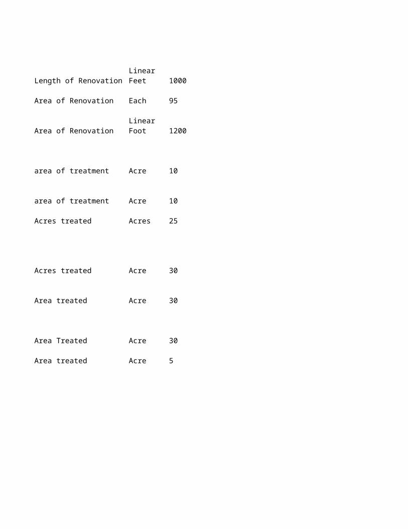
A corrugated metal (galvanized steel or aluminum) pipe culvert (CMP) of any shape (round, elliptical, or squash) used at a road-stream crossing to provide aquatic organism passage (AOP) and promote stream ecological and geomorphic function. CMPs used for AOP are sized according to geomorphic analyses, not just an estimate of runoff and streamflow at the site from the contributing watershed. In addition, CMPs used for AOP are filled with a mixture of rock and gravel sized to emulate site stream conditions and geomorphic units in the channel. The simulated streambed material is continuous throughout the culvert barrel, and blended with the intact streambed at the culvert inlet and outlet. The first estimate of culvert size--diameter or span--is obtained by analyzing bankfull channel width on a reach of stream not affected by an existing road crossing or other conditions that alter self-formed conditions. In the case of a culvert replacement, bankfull investigations are begun at least 10-20 estimated bankfull channel widths above the existing stream crossing. Culvert diameter or span is then increased according to channel bed composition and texture, bank characteristics, channel alignment at the crossing section, and other parameters that may affect channel dynamics and stability.
Once the CMP diameter or span is determined, culvert length will be determined by roadway geometry and loading requirements, and site stream conditions. Concrete headwalls and/or wingwalls may be necessary in shorter installations and/or where fill/roadway cover is limited or the stream alignment is not perpendicular to the road axis. Culvert wall thickness and corrugations are determined by road loading requirements. Stream geomorphic characteristics, including the reach longitudinal profile, channel cross-sectional shape, substrate composition and arrangement, and bank shape and composition are determined.
CMPs are installed with an assortment of equipment used for excavation, placing material, and delivering and removing material. Construction elements generally include an assortment of rock used to create riffles, cascades, or riffle-pool sequences with between 6 to 12 inches of water surface elevation drop between adjacent structures. Stream dewatering and diversion around the work site is often required, and temporary road closure or re-routing may also be required. . Channel bed material within the culvert barrel varies according to prevailing stream characteristics at the crossing site. The culvert is placed within the roadway on a subexcavated compacted bed, set at a slope that matches the design longitudinal profile, and backfilled with a bed mixture that mimics adjacent stream characteristics with special attention to channel pattern. Backfill depths are typically at least 20% of the culvert diameter or rise, but may deviate based on the shape of the culvert used, channel dimensions, substrate size, and the site longitudinal profile. Special equipment such as motorized wheelbarrows may be necessary to backfill smaller CMPs. Once the simulated streambed in the culvert barrel is complete, the roadway is replaced and any necessary armoring and revegetating material is placed at the culvert inlet and outlet where it intersects the road fill prism. Other actions include construction staking and signage, soil erosion and pollution control, removal and disposal of the old culvert, and topsoil conservation for site reclamation. Disturbed areas are revegetated with a mix of site-adapted species. Scenario does not include additional measures needed to address channel incision, bank stability, and other factors associated with the presence of the stream crossing.

A multi-plate galvanized steel or aluminum culvert (arch or box) used at a road-stream crossing to provide aquatic organism passage (AOP) and promote stream ecological and geomorphic function. They commonly attach to preformed reinforced or poured-in-place concrete footings. Bottomless culverts used for AOP are sized according to geomorphic analyses, not just an estimate of runoff and streamflow at the site from the contributing watershed. In addition, bottomless culverts used for AOP are filled with a mixture of rock and gravel sized to emulate site stream conditions and geomorphic units in the channel. The simulated streambed material is continuous throughout the culvert barrel, and blended with the intact streambed at the culvert inlet and outlet. The first estimate of culvert span is obtained by analyzing bankfull channel width on a reach of stream not affected by an existing road crossing or other conditions that alter self-formed conditions. In the case of a culvert replacement, bankfull investigations are begun at least 10-20 estimated bankfull channel widths above the existing stream crossing. Culvert span is then increased according to channel bed composition and texture, bank characteristics, channel alignment at the crossing section, and other parameters that may affect channel dynamics and stability.
Once the culvert span is determined, culvert length will be dictated by roadway geometry and loading requirements, and site stream conditions. Concrete headwalls and/or wingwalls may be necessary in shorter installations and/or where fill/roadway cover is limited or the stream alignment is not perpendicular to the road axis. Culvert wall thickness and footing requirements are determined by road loading requirements and site geotechnical investigations. Generally, the preferred footing is a T-design with a spread footing with stem wall. Connecting the culvert leg to the footing can be done by welding, grouting, bolting. Stream geomorphic characteristics, including the reach longitudinal profile, channel cross-sectional shape, substrate composition and arrangement, and bank shape and composition are determined.
Bottomless arch or box culverts are commonly delivered in sections and bolted together in the field. Smaller arches can be delivered in one piece. They are installed with an assortment of equipment used for excavation, placing material, and delivering and removing material. Construction elements generally include an assortment of rock used to create riffles, cascades, or riffle-pool sequences with between 6 to 12 inches of water surface elevation drop between adjacent structures. Stream dewatering and diversion around the work site is often required, and temporary road closure or re-routing may also be required. Channel bed material within the culvert barrel varies according to prevailing stream characteristics at the crossing site. Footings are placed or poured, and the new streambed is set at a slope that matches the design longitudinal profile, and backfilled with a bed mixture that mimics adjacent stream characteristics with special attention to channel pattern. Once the simulated streambed between the footings is complete, the culvert sections are assembled and attached to the footings. Larger rock may be placed along the footing/culvert stemwall to project the connection from damage by transported bedload. The roadway is replaced and any necessary armoring and revegetating material is placed at the culvert inlet and outlet where it intersects the road fill prism. Other actions include construction staking and signage, soil erosion and pollution control, removal and disposal of the old culvert, and topsoil conservation for site reclamation. Disturbed areas are revegetated with a mix of site-adapted species. Scenario does not include additional measures needed to address channel incision, bank

A four-sided precast concrete box (square or rectangular) culvert used at a road-stream crossing to provide aquatic organism passage (AOP) and promote stream ecological and geomorphic function. Concrete box culverts are generally available in sections of 1-foot increments. Concrete box culverts used for AOP are sized according to geomorphic analyses, not just an estimate of runoff and streamflow at the site from the contributing watershed. In addition, concrete box culverts used for AOP are filled with a mixture of rock and gravel sized to emulate site stream conditions and geomorphic units in the channel. The simulated streambed material is continuous throughout the culvert barrel, and blended with the intact streambed at the culvert inlet and outlet. The first estimate of culvert width is obtained by analyzing bankfull channel width on a reach of stream not affected by an existing road crossing or other conditions that alter self-formed conditions. In the case of a culvert replacement, bankfull investigations are begun at least 10-20 estimated bankfull channel widths above the existing stream crossing. Culvert width is then increased according to channel bed composition and texture, bank characteristics, channel alignment at the crossing section, and other parameters that may affect channel dynamics and stability.
Once the culvert width is determined, culvert length will be determined by roadway geometry and loading requirements, and site stream conditions. Concrete headwalls and/or wingwalls may be necessary in shorter installations and/or where fill/roadway cover is limited or the stream alignment is not perpendicular to the road axis. Stream geomorphic characteristics, including the reach longitudinal profile, channel cross-sectional shape, substrate composition and arrangement, and bank shape and composition are determined.
Concrete box culverts are delivered in sections and assembled onsite, and require adequate bed compaction throughout the crossing section. They are installed with an assortment of equipment used for excavation, placing material, and delivering and removing material. Construction elements generally include an assortment of rock used to create riffles, cascades, or riffle-pool sequences with between 6 to 12 inches of water surface elevation drop between adjacent structures. Stream dewatering and diversion around the work site is often required, and temporary road closure or re-routing may also be required. Channel bed material within the culvert barrel varies according to prevailing stream characteristics at the crossing site. The new streambed is set at a slope that matches the design longitudinal profile, and backfilled with a bed mixture that mimics adjacent stream characteristics with special attention to channel pattern. The roadway is replaced and any necessary armoring and revegetating material is placed at the culvert inlet and outlet where it intersects the road fill prism. Other actions include construction staking and signage, soil erosion and pollution control, removal and disposal of the old culvert, and topsoil conservation for site reclamation. Disturbed areas are revegetated with a mix of site-adapted species. Scenario does not include additional measures needed to address channel incision, bank stability, and other factors associated with the presence of the stream crossing.
RESOURCE CONCERNS: INADEQUATE HABITAT FOR FISH AND WILDLIFE –Habitat degradation; EXCESS WATER – Ponding, flooding, seasonal high water table, seeps, and drifted snow; WATER QUALITY DEGRADATION – Elevated water temperature; SOIL EROSION– Excessive bank erosion from streams shorelines or water conveyance channels

A channel-spanning structure that carries a road or trailway across a river or stream. Constructed of timber, i-beams, or concrete, bridges are attached at either end to prefabricated, reinforced and poured-in-place, or piling abutments capped/surrounded with concrete. Longer span bridges may require instream pilings to support the travel surface. Bridge decking can be timber, concrete, asphalt, or some combination thereof.
Bridge design is completed to conform to loading requirements and site conditions. Geotechnical investigations are used to determine the best support structure suited to a given site. The bridge deck is designed to rest on abutments placed on the adjacent floodplain.
Bridge components are delivered to the site and assembled by a combination of equipment and manual labor. They are installed with an assortment of equipment used for excavation, placing material, delivering and removing material, and lifting bridge components from delivery trucks onto the constructed bridge support elements. Other actions include construction staking and signage, soil erosion and pollution control, removal and disposal of the old culvert (if applicable), and topsoil conservation for site reclamation. Stream diversion is not necessary since the bridge will be constructed above the active channel. Disturbed areas are revegetated with a mix of site-adapted species. Scenario does not include additional measures needed to address channel incision, bank stability, and other factors associated with the presence of the bridge crossing.
RESOURCE CONCERNS: INADEQUATE HABITAT FOR FISH AND WILDLIFE –Habitat degradation; EXCESS WATER – Ponding, flooding, seasonal high water table, seeps, and drifted snow; WATER QUALITY DEGRADATION – Elevated water temperature; SOIL EROSION– Excessive bank erosion from streams shorelines or water conveyance channels
Payments for these associated practices are made separately and are covered by other typical scenarios and payment schedules. See relevant CPS for additional information.
---Site Preparation and Reclamation associated with project footprint: (326) Clearing and Snagging, (342) Critical Area Planting, (382) Fence, (390) Riparian Herbaceous Cover, (391) Riparian Forest Buffer, (612) Tree/Shrub Establishment;
---Reach Planning/Habitat Enhancement: (395) Stream Habitat Improvement and Management,
---Structural Measures Associated with Scenario but outside of project footprint: (410) Grade Stabilization Structure, (582) Open Channel, (584) Channel Bed Stabilization, (580) Streambank and Shoreline Protection

Formed, reinforced, poured-in-place concrete structures outfitted with baffles (Denil), vertical slots, pools and weirs, submerged orifices, chutes or some combination thereof to provide upstream passage for aquatic organisms over dams and other hydraulic structures. Although fish ladder designs vary according to target species and site conditions, they can generally be described as a three-sided concrete channel with integrated hydraulic features that provide a gradual elevation increase across some distance that allows aquatic organism to swim over a barrier--they convert the total barrier head elevation into passable increments. Concrete ladders are often constructed with resting pools and may have switchbacks. The primary water source for a concrete ladder comes from streamflow diverted into the ladder exit (upstream end) and since it is passed through the ladder to the river below, it is not a consumptive use. These ladders often require flow control and regulating devices (sometimes automated), gates, and may need auxiliary pumps to provide attraction flows at the ladder entrance (downstream end) or augment flow in the ladder. Gages above and below the dam are required to inform ladder operation. Trash racks are used at the upstream end to block debris from entering the ladder. Concrete ladders also require frequent maintenance, and flow through unautomated ladders may need to be adjusted manually when adjacent river conditions or dam operations change.
Concrete ladder designs can be complex and require interactions between engineering and ecological sciences for successful implementation. For example, the ladder entrance is one of the most important elements of the structure, and placement of this entrance in the downstream reach is a function of site characteristics and aquatic organism biology. In addition, some aquatic animals will not swim through a submerged orifice, so use of pool-orifice ladders is not recommended. Partners associated with dam ownership and operation, regulatory agencies, and others are consulted and included in the design and construction process. Ladder designs account for run volume and timing, and the swimming capabilities of target species. Some ladders in highly visible areas are finished with masonry facades to blend the ladder to the site in the interest of aesthetics or to conform with historic appearances.
Concrete ladders are constructed with equipment for excavation, placing material, and delivering and removing material. Lifts or booms are required to place concrete into forms. Because ladders are often attached to existing dams, personnel familiar with the dam structure are involved at all phases of the process to ensure that plans conform with site requirements. Bed and bank excavation are necessary to create the location for concrete ladders, so site isolation and sediment and erosion control measures are used. Disturbed areas are revegetated with a mix of site-adapted species, and access control and signage are provided. Scenario does not include additional measures in the adjacent active channel necessary to control flow, address channel elevation or stability, or encourage fish guidance into the concrete ladder. Scenario does not include structures used as counting stations or to trap and sample upstream migrants.
RESOURCE CONCERNS: INADEQUATE HABITAT FOR FISH AND WILDLIFE –Habitat degradation
Payments for these associated practices are made separately and are covered by other typical scenarios and payment

Denil fishways are roughened chutes that employ baffles connected to the walls and floor of the chute to provide near continuous energy dissipation throughout the fishway length. Denils are often reinforced, poured-in-place concrete structures outfitted with removable baffles constructed with treated wood that fits into channels incorporated into the ladder walls. These fishways have excellent attraction characteristics when properly sited and provide good passage conditions using relatively low flow amounts. They often do not require auxiliary (pumped) attraction or fishway flow, but are sensitive to tailwater fluctuations. Denil fishways are used mainly for sites where the fishway can be closely monitored, such as off-ladder fish trap designs or temporary fishways used during construction of permanent passage facilities. Because of their baffle geometry and narrow flow paths, Denil fishways are especially susceptible to debris accumulation.
Denil fishways are designed with a sloped channel that has a constant discharge for a given normal depth, chute gradient, and baffle configuration. Energy is dissipated consistently throughout the length of the fishway via channel roughness, and results in an average velocity compatible with the swimming ability of native aquatic organisms. Target species' mobility data are important factors in determing the length of a Denil or steeppass because there are no resting locations within a given length of these fishways. Once an animal starts to ascend a length of Denil, it must pass all the way upstream and exit the fishway, or risk injury when falling back downstream. If the Denil or steeppass fishway is long, intermediate resting pools may be included in the design, located at intervals determined by the swimming ability of the weakest target species.
Denil ladders are constructed with equipment used for excavation, placing material, and delivering and removing material. Lifts or booms may be required to place concrete into forms or lift ladder elements into place. Because ladders are often attached to existing dams, personnel familiar with the dam structure are involved at all phases of the process to ensure that plans conform with site requirements. Bed and bank excavation may be necessary to create the location for fishway components, so site isolation and sediment and erosion control measures are used. Disturbed areas are revegetated with a mix of site-adapted species, and access control and signage are provided. Scenario does not include additional measures in the adjacent active channel necessary to control flow, address channel elevation or stability, or encourage fish guidance into the concrete ladder. Scenario does not include structures used as counting stations or to trap and sample upstream migrants.
RESOURCE CONCERNS: INADEQUATE HABITAT FOR FISH AND WILDLIFE –Habitat degradation
Payments for these associated practices are made separately and are covered by other typical scenarios and payment schedules. See relevant CPS for additional information.
---Site Preparation and Reclamation associated with project footprint: (326) Clearing and Snagging, (342) Critical Area Planting, (382) Fence, (390) Riparian Herbaceous Cover, (391) Riparian Forest Buffer, (612) Tree/Shrub Establishment

Alaskan Steeppass fishways are roughened chutes that employ baffles connected to the walls and floor of the chute to provide near continuous energy dissipation throughout the fishway length. A Steeppass is commonly constructed of welded aluminum at an offsite fabrication facility that is later transported to the project site and lowered in place with a boom truck or crane. Steeppasses can be composed of a single length of chute, or chutes connected by reinforced, poured-in-place resting/turn pools at complex or higher barrier sites. These fishways have excellent attraction characteristics when properly sited and provide good passage conditions using relatively low flow amounts. They often do not require auxiliary (pumped) attraction or fishway flow, but are sensitive to tailwater fluctuations. Steeppass fishways are used mainly for sites where the fishway can be closely monitored, such as off-ladder fish trap designs or temporary fishways used during construction of permanent passage facilities. Because of their baffle geometry and narrow flow paths, steeppass fishways are especially susceptible to debris accumulation.
Steeppass fishways are designed with a sloped channel that has a constant discharge for a given normal depth, chute gradient, and baffle configuration. Energy is dissipated consistently throughout the length of the fishway via channel roughness, and results in an average velocity compatible with the swimming ability of native aquatic organisms. Target species' mobility data are important factors in determing the length of a Denil or steeppass because there are no resting locations within a given length of these fishways. Once an animal starts to ascend a length of steeppass, it must pass all the way upstream and exit the fishway, or risk injury when falling back downstream. If the steeppass fishway is long, intermediate resting pools may be included in the design, located at intervals determined by the swimming ability of the weakest target species.
Steeppass fishways are constructed with equipment used for excavation, placing material, and delivering and removing material. Lifts or booms may be required to place concrete into forms or lift steeppass sections into place. Because ladders are often attached to existing dams, personnel familiar with the dam structure are involved at all phases of the process to ensure that plans conform with site requirements. Bed and bank excavation may be necessary to create the location for fishway components, so site isolation and sediment and erosion control measures are used. Disturbed areas are revegetated with a mix of site-adapted species, and access control and signage are provided. Scenario does not include additional measures in the adjacent active channel necessary to control flow, address channel elevation or stability, or encourage fish guidance into the concrete ladder. Scenario does not include structures used as counting stations or to trap and sample upstream migrants.
RESOURCE CONCERNS: INADEQUATE HABITAT FOR FISH AND WILDLIFE –Habitat degradation
Payments for these associated practices are made separately and are covered by other typical scenarios and payment schedules. See relevant CPS for additional information.
---Site Preparation and Reclamation associated with project footprint: (326) Clearing and Snagging, (342) Critical Area Planting, (382) Fence, (390) Riparian Herbaceous Cover, (391) Riparian Forest Buffer, (612) Tree/Shrub Establishment

Structure installed on low volume or on unimproved roads at watercourse crossings. Primary use is to allow livestock and equipment access to other parcels of land or operational units. Low-water crossings provide safe and stable stream crossings that don’t negatively impact water and ecological quality while remaining stable across a wide range of flows. Variations exist, but a common application consists of an improved or hardened ford located above a hydraulic control (e.g., bedrock outcropping, riffle, or step composed of coarse substrates). Properly designed and installed low water crossings provide aquatic organism passage (AOP), promote stream ecological and geomorphic function, remain stable over time, and can pass sediment and woody debris.
Conservation planning and interaction with the landowner is vital to determine if existing crossings can be consolidated into fewer, more reliable locations. Characterizing a site according to its watershed position and geomorphic function will aid design decisions. Optimal AOP conditions are usually realized when the backfill is composed of a mixture that mimics bed material as evaluated from a reference reach adjacent to the crossing—preferably at least 10-20 estimated bankfull channel widths above an existing crossing to avoid effects that alter channel geometry or bedform composition and spacing.
Low water crossings are installed with an assortment of equipment used for excavation, placing material, and delivering and removing material. Low water crossings provide the best mix of function and longevity when they are designed and built to conform to existing channel geometry and slope, constructed to match the shape of the existing channel, and oriented to cross the stream at a 90 degree angle. Crossing width, measured along the downstream axis, should not exceed 2X bankfull width. Low water crossings are commonly constructed by overexcavating the crossing section 6-12 inches below the existing streambed and backfilling the void with well-graded rock back to natural bed elevation. Geotextile lining may be required in some settings. Rock size and gradation is the smallest mix needed to remain stable under prevailing flow conditions—larger rock can endanger livestock and turbulence impairs passage. Sand or soil may be added into the mix to seal the section to ensure that the stream doesn’t percolate into the crossing substrate. Smaller material increases bed diversity, chokes voids between bigger stones, and helps preserve passage quality. Smaller rock smaller (< 2 inches) at the finished surface may become lodged in livestock hooves. The road/trail surface of the crossing should be extended to an elevation that exceeds the known high water level on each side of the crossing. The downstream edge of the crossing should not produce a sharp drop in water surface to preserve AOP quality and discourage sediment deposition and debris accumulation. Other actions include construction staking and signage, soil erosion and pollution control, removal and disposal of the old culvert, and topsoil conservation for site reclamation. Disturbed areas are revegetated with a mix of site-adapted species. Scenario does not include additional measures needed to address channel incision, bank stability, and other factors associated with the presence of the stream crossing. Stream corridor fencing should be considered to control livestock access and preserve water and riparian quality.
RESOURCE CONCERNS: INADEQUATE HABITAT FOR FISH AND WILDLIFE –Habitat degradation

A fish screen used at surface (gravity) diversions intended to prevent juvenile or small-bodied adult fish from entering ditches, canals, laterals or other pathways that lead to migration dead-ends or sources of mortality. Paddlewheel screens are active by design, meaning that they are outfitted with mechanisms that automatically cycle to keep the screen free of debris that will restrict the screen area, impede flow through the screen, and may cause the screen to fail. These screens are powered by a paddlewheel driven by flowing water and are thus suitable for remote locations without electrical services. Paddlewheel screens can be installed in the active channel along a streambank, but are most commonly built in a canal below a diversion structure. Aquatic organisms that encounter a screen installed in a canal are diverted back into the adjacent stream through a buried pipe.
Screens installed in the active channel are built at the point of diversion with the screen face aligned parallel to the flow of the river. Bankline modifications can be necessary to achieve proper alignment. Screens installed in a canal can be aligned differently and are best sited at a canal location that minimizes the straight-line bypass/return path distance. Again, canal installation is the most common.
A fully functional screen is designed to meet criteria intended to protect target organisms from being swept into and pinned against or along the screen face (impingement). When this occurs, animals can be physically harmed or, in the case of a rotating drum screen, introduced into the diversion works behind the screen. Active screens are designed to ensure that the approach velocity will not exceed .4 feet per second (fps). Approach velocity is calculating by dividing the maximum screened flow volume by the vertical projection of the effective screen area at maximum submergence. For a rotating drum screen the design submergence should not be more than 85% or less than 65% of the screen diameter. Screen design should strive to provide nearly uniform flow distribution across the screen surface. Screens longer than 6 feet must be angled to the direction of incoming flow and have sweeping velocities (along the face of the screen) greater than the approach velocity, and sweeping velocities should not decrease along the face of the screen. Screen face openings must not exceed 3/32 inch in diameter, and perforated plate must be smooth to the touch with openings punched through in the direction of approaching flow. Material used for the screen face should be corrosion resistant and sufficiently durable to maintain a smooth uniform surface with long term use. Bypass design flow should be about 5% of the diverted amount, include an easily accessible entrance, and flow velocity in the bypass pipe or channel should not exceed 0.2fps. Minimum design depth in a bypass pipe should be at least 40% of the pipe diameter. Bypass entrances should be installed with independent flow control capability. The face of all screen surfaces must be placed flush (to the extent possible) with any adjacent screen bay, pier noses, and walls to allow fish unimpeded movement parallel to the screen face and ready access to bypass routes.
Paddlewheel screens are generally fabricated at a machine shop and delivered to the project site. Site conditions may require the construction of a small concrete headwall that will anchor the screen and may be outfitted with flow control that to adjust hydraulic conditions and optimize screen function. In addition, concrete training walls to conduct flow into, through, and below the screen may be required at some sites. Paddlewheel screens are installed

A fish screen used at surface (gravity) diversions intended to prevent juvenile or small-bodied adult fish from entering ditches, canals, laterals or other pathways that lead to migration dead-ends or sources of mortality. Rotating drum screens are active by design, meaning that they are outfitted with mechanisms that automatically cycle to keep the screen free of debris that will restrict the screen area, impede flow through the screen, and may cause the screen to fail. These screens are powered electric motors that rotate a drum covered in fine stainless steel mesh. The drum rotates in the direction of the incoming flow, and is designed to protect fish from entrainment into the diversion while at the same time rolling fine debris attached to the screen face into the ditch or canal below. Rotating drum screens can be installed in the active channel along a streambank, but are most commonly built in a canal below a diversion structure. . Aquatic organisms that encounter a screen installed in a canal are diverted back into the adjacent stream through a buried pipe.
Screens installed in the active channel are built at the point of diversion with the screen face aligned parallel to the flow of the river. Bankline modifications can be necessary to achieve proper alignment. Screens installed in a canal can be aligned differently and are best sited at a canal location that minimizes the straight-line bypass/return path distance. Again, canal installation is the most common.
A fully functional screen is designed to meet criteria intended to protect target organisms from being swept into and pinned against or along the screen face (impingement). When this occurs, animals can be physically harmed or, in the case of a rotating drum screen, introduced into the diversion works behind the screen. Active screens are designed to ensure that the approach velocity will not exceed .4 feet per second (fps). Approach velocity is calculating by dividing the maximum screened flow volume by the vertical projection of the effective screen area at maximum submergence. For a rotating drum screen the design submergence should not be more than 85% or less than 65% of the screen diameter. Screen design should strive to provide nearly uniform flow distribution across the screen surface. Screens longer than 6 feet must be angled to the direction of incoming flow and have sweeping velocities (along the face of the screen) greater than the approach velocity, and sweeping velocities should not decrease along the face of the screen. Screen face openings must not exceed 3/32 inch in diameter, and perforated plate must be smooth to the touch with openings punched through in the direction of approaching flow. Material used for the screen face should be corrosion resistant and sufficiently durable to maintain a smooth uniform surface with long term use. Bypass design flow should be about 5% of the diverted amount, include an easily accessible entrance, and flow velocity in the bypass pipe or channel should not exceed 0.2fps. Minimum design depth in a bypass pipe should be at least 40% of the pipe diameter. Bypass entrances should be installed with independent flow control capability. The face of all screen surfaces must be placed flush (to the extent possible) with any adjacent screen bay, pier noses, and walls to allow fish unimpeded movement parallel to the screen face and ready access to bypass routes.
Rotating drum screens are composed of elements fabricated at a machine shop and delivered to the project site, or built onsite. They are generally part of a reinforced, poured-in-place mass of concrete that forms a three-sided This scenario addresses the resource concern of inadequate wildlife habitat for pollinators. It provides both physical habitat by providing areas that are not disturbed by annual tillage and provides pollen and nectar throughout the growing season by establishing a diverse mixture of flowering shrubs. Typically a mixture of 5 or more species is planted to improve diversity so that pollen and nectar are available as long as possible. Typical installation is in or at the edge of cropland or pasture. Typical installation involves tillage to prepare the site for planting. Flowering shrubs adapted for local climatic and edaphic conditions are typically planted at eight foot intervals (this will vary with species selection and density goals). The species listed in the component section of this scenario are strictly for deriving a cost. Species adapted to local climatic and edaphic conditions will be listed in the specification for the site. There is tremendous overlap between this practice and conservation practice 380 Windbreak/Shelterbelt establishment. The main difference is that conservation practice 380 is exclusively woody plants where practice 422 provides for the use of herbaceous materials. If a fence is needed to facilitate establishment use practice 382, Fence.
Typically installation of this scenario is within an annually cropped field. The hedgerow is planted on the contour to provide a physical and visual aid to contour farming. This scenario is used to facilitate additional measures that address the resource concerns of sheet and rill soil erosion and Water Quality Degradation, excess sediment in surface waters. Trees, shrubs, and grasses adapted for local climatic and edaphic conditions are typically planted at eight foot intervals (this will vary with species selection and density goals). Species selected should be at least three feet tall at maturity.

This scenario is for machine planting of woody species. Typically installed in or at the edge of cropland or pasture this scenario is used to address the Inadequate Habitat for Fish and Wildlife resource concern. Specifically, the establishment of dense vegetation in a linear design can be used to provide for several habitat elements depending on the needs identified in the habitat assessment. This scenario can provide habitat connectivity, food, and cover for wildlife depending on design and plant species selection. The 422 standard for wildlife criteria calls for a minimum of two species of native plants. Typical installation involves tillage to prepare the site for planting. At least 2 tree and/or shrub species adapted for local climatic and edaphic conditions are typically planted at eight foot intervals (this will vary with species selection and density goals). Tree tubes or other protection from animal damge will be provided. The species listed in the component section of this scenario are strictly for deriving a cost. Plant species adapted to the local climatic and edaphic conditions that address the resource concern will be stated in the specification for the site. There is tremendous overlap between this practice and conservation practice 380 Windbreak/Shelterbelt establishment. The main difference is that conservation practice 380 is exclusively woody plants where practice 422 provides for the use of herbaceous materials. If a fence is needed to facilitate establishment use practice 382, Fence.
Typically installed in or at the edge of cropland or pasture this scenario is used to address the Inadequate Habitat for Fish and Wildlife resource concern. Specifically, the establishment of dense vegetation in a linear design can be used to provide for several habitat elements depending on the needs identified in the habitat assessment. This scenario can provide: habitat conectivity, food, and cover for wildlife depending on design and plant species selection. The 422 standard for wildlife criteria calls for a minimum of two species of native plants.Typical installation involves tillage to prepare the site for planting. At least 2 tree and/or shrub species adapted for local climatic and edaphic conditions are typically planted by hand at eight foot intervals (this will vary with species selection and density goals). A native cool season grass or mixture adapted to the local climatic and edaphic conditions will be drilled into the site at a rate that will achieve a minimum of 20 seeds per square foot prior to planting the trees. The species listed in the component section of this scenario are strictly for deriving a cost. Plant species adapted to the local climatic and edaphic conditions that address the resource concern will be stated in the specification for the site. There is tremendous overlap between this practice and conservation practice 380 Windbreak/Shelterbelt establishment. The main difference is that conservation practice 380 is exclusively woody plants where practice 422 provides for the use of herbaceous materials. If a fence is needed to facilitate establishment use practice 382, Fence.
Artificial nesting structures such as goose platforms are used to increase reproductive success of species such as waterfowl, bats and native pollinators in areas where natural nest sites are unavailable or unsuitable. Although artificial nesting structures cannot replace natural nesting habitats, they can increase the number of nesting sites available in an area. These structures are designed to meet targeted species biology and life history needs.

Setting is any lands with the potential to provide wetland wildlife habitat and that potential is not currently being captured. The identified wetland wildlife habitat limiting factors can be restored, enhanced or created, with the application of this practice alone, or in combination with other supporting and facilitating practices. Monitoring will be used to determine if the conservation system meets or exceeds the minimum quality criteria for the targeted wildlife. Management will be implemented based on the findings of the habitat assessment and monitoring.Wetland wildlife habitat management and monitoring needed to treat the resource concerns may require training, no qualitative data assessment, no water quality monitoring and is medium in complexity and intensity. Examples of prescribed monitoring, include but are not limited to: photo points taken, documentation of livestock use, regeneration/breeding success, completing an annual management records log, documenting wildlife sightings, documenting location and species of invasive plants and condition of vegetative and structural treatments. Decisions or treatments associated with this practice or facilitating practices will require income foregone. The planner will specify locations and identify the methods to the customer who will implement the monitoring and management plan. Facilitating practices may include but not limited to: 314, 315, 327, 342, 380, 384, 390, 391, 422, 472, 490, 511, 528, 550, 612, 647, 650, 654, 660, 666.
The setting is all landuses, but typically is on lands used for the production of forest products, grazing, and/or fish and wildlife where the slope gradient is less than two percent and soils that are not excessivly drained. The construction of low intensity and low complexity topographic features will provide for diverse soil hydrologic conditions needed to treat the degraded plant condition and/or inadequate habitat for wetland wildlife. The contruction of micro and macro topographic featuires can be implemented with the use of equipment with less than 70 HP. This scenario is for earthwork, not associated with habitat structures or any other national standard.
Monitor grouse populations to determine population status and help document the success or effects of habitat management practices. Setting is any lands supporting upland grouse lek habitat. Management may be implemented or modified based on the findings of the habitat assessment and monitoring. Lek monitoring and record-keeping requires training to learn the state wildlife agency protocols. Facilitating practices may include but are not limited to: 314, 315, 327, 342, 390, 391, 422, 472, 490, 511, 528, 550, 612, 647, 650, 654, 660, 666.
This scenario is typically used on cropland, but may be used on all upland habitats for the establishment of annual vegetation on all land uses. This scenario is utilized when a habitat assessment indicates food and/or cover are limiting factors for wildlife, including pollinators. The typical size range for this scenario is 1/2 to 5 acres. This scenario would be applied on any land use where habitats are utilized by targeted species. This practice scenario is typically used to reduce soil erosion, reduce soil quality degradation, improve water quality and develop wildlife habitat as part of a habitat management system. This scenario may be used to temporarily provide cover or forage while permanent vegetation is being established. Establishment of vegetation will require methods including light disking, herbicide application and use of seed drill for planting. Fertilization may be required and will be completed in response to a soil test.
This scenario covers low elevation, dry forest habitats, primarily ponderosa pine, where an approved habitat assessment has indicated that a lack of snags is limiting cavity nesting bird reproduction. Snags are created by cutting off the approximate upper third of a large diameter ponderosa pine, western larch or Douglas fir with a chain saw after climbing the tree using climbing spurs. This requires skilled labor by a qualified logger. The goal is to provide a minimum of three large diameter snags per acre throughout the scenario unit.

This scenario addresses inadequate habitat for fish and wildlife on cropland. The resource concern is addressed by providing shallow water habitat for wildlife such as shorebirds, waterfowl, wading birds, mammals, fish, reptiles, amphibians, and other species that require shallow water for at least part of their life cycle. Sites are flooded up to a depth of 18" with an average depth based on foraging depths for the waterbird guild of concern. Water is provided by natural flooding and/or precipitation.
This scenario addresses inadequate habitat for fish and wildlife on cropland. To facilitate practice code 643, 644, 645, or 395, seasonal shallow water is provided annually for target species by purchasing of water, lifting of such water, monitoring of the water quality, response by target plant community, use by target flora or fauna. Sites are flooded up to a depth of 18"with an average depth based on foraging depths for the waterbird guild of concern. Monitoring and adaptive management accomplished of existing water control structures is accomplished to meet very specific conditions needed to address previously identified degraded plant conditions or inadequate habitat for fish and/or wildlife. This high-level managmenet is applied to lands used for crop, pasture, hay, forests or wildlife lands where target flora and fauna have been identified as a primary concern. Loss of some level of crop, forage, hay or forest production may occur depending on site specific conditions.
A Mineral Flat wetland is to be restored. The tract size is 160 acres consisting of surface saturated soils interspersed with shallow depressions that are not depressional class HGM wetlands. The wetland size is also 160 acres. Resource Concerns are: 4-SOIL QUALITY DEGRADATION - Organic matter depletion, 11- WATER QUALITY DEGRADATION - Excess nutrients in surface and ground waters, 12 - WATER QUALITY DEGRADATION - Pesticides transported to surface and ground waters, 16 - WATER QUALITY DEGRADATION - Excessive sediment in surface waters, 18 - DEGRADED PLANT CONDITION - Undesirable plant productivity and health, 19 - DEGRADED PLANT CONDITION, Inadequate strucuture and composition, 22- INADEQUATE HABITAT FOR FISH AND WILDLIFE - Habitat degradation.
A Riverine HGM tract on a large floodplain is to be restored. It has been converted to agricultural production by surface ditching and clearing of woody vegetation. The size of the tract is 100 acres. The wetland extent is 60 acres, and 40 acres are adjacent non-wetland. Resource Concerns are: 4-SOIL QUALITY DEGRADATION - Organic matter depletion, 11- WATER QUALITY DEGRADATION - Excess nutrients in surface and ground waters, 12 - WATER QUALITY DEGRADATION - Pesticides transported to surface and ground waters, 16 - WATER QUALITY DEGRADATION - Excessive sediment in surface waters, 18 - DEGRADED PLANT CONDITION - Undesirable plant productivity and health, 19 - DEGRADED PLANT CONDITION, Inadequate strucuture and composition, 22- INADEQUATE HABITAT FOR FISH AND WILDLIFE - Habitat degradation.
A Depressional HGM class wetland is to be restored. The tract size is 15 acres, and the actual wetland size is 10 acres. The site is a recharge depression, fed only from surface runoff. Resource Concerns are: 4-SOIL QUALITY DEGRADATION - Organic matter depletion, 11- WATER QUALITY DEGRADATION - Excess nutrients in surface and ground waters, 12 - WATER QUALITY DEGRADATION - Pesticides transported to surface and ground waters, 16 - WATER QUALITY DEGRADATION - Excessive sediment in surface waters, 18 - DEGRADED PLANT CONDITION - Undesirable plant productivity and health, 19 - DEGRADED PLANT CONDITION, Inadequate strucuture and composition, 22- INADEQUATE HABITAT FOR FISH AND WILDLIFE - Habitat degradation.

A Riverine HGM landscape on a small stream on a low stream order riparian landscape has been converted to agricultural production. The stream channel has degraded. The reach is 1500 feet in length, and the tract size is 15 acres. The wetland area is 10 acres. Resource Concerns are: 4-SOIL QUALITY DEGRADATION - Organic matter depletion, 11- WATER QUALITY DEGRADATION - Excess nutrients in surface and ground waters, 12 - WATER QUALITY DEGRADATION - Pesticides transported to surface and ground waters, 16 - WATER QUALITY DEGRADATION - Excessive sediment in surface waters, 18 - DEGRADED PLANT CONDITION - Undesirable plant productivity and health, 19 - DEGRADED PLANT CONDITION, Inadequate strucuture and composition, 22- INADEQUATE HABITAT FOR FISH AND WILDLIFE - Habitat degradation.
A wetland is created on a flat mineral upland at a location where surface runoff may be intercepted and ponded by excavation. Resource concerns are 22 - INDEQUATE HABITAT FOR FISH AND WILDLIFE - Habitat degradation.
A Mineral Flat wetland is to be enhanced. The tract size is 160 Acres consists of surface saturated soils interspersed with shallow depressions that are not depressional class HGM wetlands. The wetland size is also 160 acres. Resource Concerns are: 4-SOIL QUALITY DEGRADATION - Organic matter depletion, 11- WATER QUALITY DEGRADATION - Excess nutrients in surface and ground waters, 12 - WATER QUALITY DEGRADATION - Pesticides transported to surface and ground waters, 16 - WATER QUALITY DEGRADATION - Excessive sediment in surface waters, 18 - DEGRADED PLANT CONDITION - Undesirable plant productivity and health, 19 - DEGRADED PLANT CONDITION, Inadequate strucuture and composition, 22- INADEQUATE HABITAT FOR FISH AND WILDLIFE - Habitat degradation.
A Riverine HGM tract on a large floodplain is to be enhanced. It has been converted to agricultural production by surface ditching and clearing of woody vegetation. The size of the tract is 100 acres. The wetland extent is 60 acres, and 40 acres are adjacent non-wetland. Resource Concerns are: 4-SOIL QUALITY DEGRADATION - Organic matter depletion, 11- WATER QUALITY DEGRADATION - Excess nutrients in surface and ground waters, 12 - WATER QUALITY DEGRADATION - Pesticides transported to surface and ground waters, 16 - WATER QUALITY DEGRADATION - Excessive sediment in surface waters, 18 - DEGRADED PLANT CONDITION - Undesirable plant productivity and health, 19 - DEGRADED PLANT CONDITION, Inadequate strucuture and composition, 22- INADEQUATE HABITAT FOR FISH AND WILDLIFE - Habitat degradation.
A Depressional HGM class wetland is to be enhanced. The tract size is 15 acres, and the actual wetland size is 10 acres. The site is a recharge depression, fed only from surface runoff. Resource Concerns are: 4-SOIL QUALITY DEGRADATION - Organic matter depletion, 11- WATER QUALITY DEGRADATION - Excess nutrients in surface and ground waters, 12 - WATER QUALITY DEGRADATION - Pesticides transported to surface and ground waters, 16 - WATER QUALITY DEGRADATION - Excessive sediment in surface waters, 18 - DEGRADED PLANT CONDITION - Undesirable plant productivity and health, 19 - DEGRADED PLANT CONDITION, Inadequate strucuture and composition, 22- INADEQUATE HABITAT FOR FISH AND WILDLIFE - Habitat degradation.
A Riverine HGM landscape on a small stream on a low stream order riparian landscape has been converted to agricultural production. The stream channel has degraded. The reach is 1500 feet in length, and the tract size is 15 acres. The wetland area is 10 acres. Resource Concerns are: 4-SOIL QUALITY DEGRADATION - Organic matter depletion, 11- WATER QUALITY DEGRADATION - Excess nutrients in surface and ground waters, 12 - WATER QUALITY DEGRADATION - Pesticides transported to surface and ground waters, 16 - WATER QUALITY DEGRADATION - Excessive sediment in surface waters, 18 - DEGRADED PLANT CONDITION - Undesirable plant productivity and health, 19 - DEGRADED PLANT CONDITION, Inadequate strucuture and composition, 22- INADEQUATE HABITAT FOR FISH AND WILDLIFE - Habitat degradation.

A structure is provided to support the nesting and rearing of targeted species such as blue birds and wood ducks. These structures are designed to meet targeted species biology and life history needs. They are used when a habitat assessment has indicated cover is a limiting factor.
A structure is provided to support the nesting and rearing of targeted species such as bats and pollinators. These structures are designed to meet targeted species biology and life history needs. They are used when a habitat assessment has indicated cover is a limiting factor.
A structure is provided to support the nesting and rearing of targeted species, such as bats, pollinators, birds and waterfowl and is mounted on an existing structure or tree. These structures are designed to meet targeted species biology and life history needs. They are used when a habitat assessment has indicated cover is a limiting factor.
A structure is provided to improve wildlife habitat by providing a burrowing owl burrow. These structures are designed to meet targeted species biology and life history needs. Two nesting locations are provided per site. Each nesting site has two points of access. The two nest locations may also be connected.
A structure is provided to improve aquatic habitat by providing alternative cover when natural cover is not readily available. These structures are designed to enhance habitat by simulating an overhanging/undercut bank. The resulting cavity provides cover and temperature attenuation to support aquatic organism biology and life history needs. A structure made of wood is placed at the toe of a slope on a rock base. The structure is then weighted with rock and covered.
A brush pile or rock pile provides improved wildlife habitat by providing resting and escape cover. These structures are located and constructed to meet targeted species biology and life history needs. While size varies, brush piles are typically 10 ft in diameter and 6 ft high at the center. Multiples brush piles are better than one larger pile, and two to four piles per acre of area adjacent to woodlands is desirable. Piles are typically 200 to 300 ft apart. Stumps, logs, rocks and pipes are typically placed at the bottom with limbs and leaves placed on top, thereby allowing easy access to the bottom of the pile. These piles can provide nesting habitat, resting areas, concealment, and protection from some predators for birds, rabbits, and other small mammals. Rock piles provide shelter and basking areas for amphibians and reptiles such as frogs, lizards, salamanders and snakes. Large rocks are typically placed at the bottom. Often depressions are dug in the ground surface and covered with flat rocks to create temporary pools for breeding frogs and salamanders. Rocks absorb heat in the day and radiate heat at night. Materials for brush and rock piles are collected locally.
Markers made from vinyl undersill material or purchased are installed on fences to increase visibility to and prevent mortality of sage-grouse and other wildlife. A fence one mile (5280 feet) long encloses a 40 acre grazing unit. The practice is installed using general labor without supervision with use of common hand tools and small equipment. Scenario may only be contracted for one year.
Fences are retrofitted to meet wildlife-friendly fence guidelines by adjusting wire spacing, replacing barbed wire with smooth wire, making wires more visible, and reducing perching opportunities for avian predators. Fence markers, perch deterrents, and new wire may be installed to accomplish the objectives when needed to prevent wildlife mortality. Typically 1,320 foot of fence is replaced with 16 1/2-foot spacing of posts.
Escape Ramps are installed in livestock watering facilities that currently lack effective wildlife escape devices to prevent sage-grouse and other wildlife from drowning. Escape Ramps must: meet the inside wall of the trough; reach to the bottom of the trough; be firmly secured to the trough rim; be built of grippable, long-lasting materials; and have a slope no steeper than 45 degrees. Typically there is one livestock watering facility needing an escape ramp in every 640 acre grazing unit. The practice is installed using general labor without supervision with use of common hand tools and small equipment. Scenario may only be contracted for one year.

Scenario Measurement
Acre 0.5
Acre 0.5
Scenario Unit
Scenario TypicalSize
Acres of Riparian Herbaceous Cover
Acres of Riparian Herbaceous Cover

Acre 0.5
acres Acre 2
Acre 1
Acres of Riparian Herbaceous Cover
Bankfull width x reach length

Acre 1
Acre 1
Bankfull width x reach length
stream length X bankfull width

Cubic Yard Cubic Yard 5
Cubic Yard 250Cubic Yards of concrete in dam and abutments (if present)

Cubic Yard 500Cubic Yards of earthen embankment

Cubic Yard 200Cubic Yards of mineral sediment, fill or large woody material

Acre 1Acres of constructed fishway (bankfull width X total length/43,650)

CMP 40Linear Foot

Rock fill Cubic Yard 75

1440Square footage of concrete box culvert
Square Foot

Linear feet of bridge deck 30Linear Foot

Barrier height (feet) 20Vertical Feet

Barrier Height (ft) 12Vertical Feet

Barrier Height (ft) 8Vertical Feet

Cubic Yard Cubic Yard 60

CFS 5Cubic Feet/Second

CFS 75
Length of Hedgerow Feet 800
Length of Hedgerow Feet 800
Cubic Feet/Second

Length of Hedgerow Feet 800
Length of Hedgerow Feet 800
Each Each 4

Acre 100
Acre 100
Each Each 2
Area Planted Acre 2
Acre 20
Acres Managed and Monitored.
number and size of constructed features

Acre of shallow water Acre 1
Acre of shallow water Acre 1
Acres of Tract Acre 160
Acres of Tract Acre 100
Acres of Tract Acre 15

Acres of Tract Acre 15
Acres of Wetland Acre 5
Acres of Tract Acre 160
Acres of Tract Acre 100
Acres of Tract Acre 15
Acres of Tract Acre 15

Number Each 1
Number Each 1
Number Each 1
Number Each 1
Number Each 1
Number Each 1
Linear Foot 5280
Linear Foot 1320
1 structure / 640 acres Each 1
Linear Foot
Linear Foot