efficiently discovering and assessing vulnerabilities in...
TRANSCRIPT

Efficiently Discovering and
Assessing Vulnerabilities in Networks
Ricardo Manuel Cardoso Ai Evangelista
Dissertação para obtenção de Grau de Mestre em
Engenharia de Redes de Comunicações
Júri
Presidente: Professor Doutor Luís Eduardo Teixeira Rodrigues
Orientadores: Professor Doutor Miguel Leitão Bignolas Mira da Silva
Engenheiro Gonçalo Filipe Tomé Lages de Carvalho
Vogal: Professor Doutor Carlos Nuno da Cruz Ribeiro
Julho de 2008


I
ACKNOWLEDGEMENTS
As I look back over the last 23 years of my life, I realize that I have met a handful of key individuals to
whom I owe a great deal, as I truly believe that I wouldn’t have ended up here without their input in
one form or another.
I would like to express my gratitude to my supervisor, Prof. Dr. Miguel Mira da Silva, whose expertise,
motivation, encouragement, understanding and patience, added considerably to my graduate
experience. I appreciate his vision, aging, ethics, interaction with participants and his assistance in
writing reports. I would like to thank the other members of my advisory team, Dr. José João Costa and
Eng. Gonçalo Carvalho for the assistance they provided at all levels of the research project and for
taking time out from their busy schedule to serve as my external reader.
I would also like to thank my family for the support they provided me through my entire life and in
particular, I must acknowledge my best friend, Juliana, without whose love, encouragement and
editing assistance, I would not have finished this thesis.
II
ABSTRACT
The importance of network topology discovery cannot be denied, especially for tasks like network
management and network auditing. Given the dynamic nature and the rising complexity of today's IP
networks, manually keeping track of topology information is an overwhelming task.
For an accurate network discovery, almost all evaluated solutions require the configuration of SNMP
agents on nearly all network devices, a requirement only feasible within a network management
approach. In practice, several algorithms have been designed to either perform in a predefined or
predicted manner, otherwise providing evidence to be ineffective at all. This situation clearly
persuades the development of effective, intelligent and general-purpose algorithmic solutions for
automatically discovering the latest physical topology of an IP network. We describe a novel approach
of a network discovery technique as a result of combining several scanning methods and an intelligent
algorithm, and propose a customized vulnerability scan engine.
As a result, we implemented and evaluated this extremely efficient ―all-in-one‖ vulnerability
assessment framework on three different network case studies, demonstrating its effectiveness.
KEYWORDS
Network Discovery, Network Topology, IT Asset Manager, Vulnerability Assessment, Network Security

III
RESUMO
A importância da descoberta da topologia de rede não pode ser negada, sobretudo para tarefas como
gestão de rede ou auditoria de rede. Dada a natureza dinâmica e a crescente complexidade das
redes actuais, manualmente manter a informação de mapeamento de rede é uma tarefa imensa e
desnecessária.
Para uma rigorosa descoberta de rede, sensivelmente todas as soluções avaliadas exigem a
configuração de agentes SNMP em quase todos os dispositivos de rede, um requisito que só pode
ser garantido numa abordagem de gestão de rede. Os algoritmos existentes funcionam de um modo
predefinido ou previsto, que na realidade não se revelam eficazes. Esta situação persuade
claramente o desenvolvimento de soluções algorítmicas eficazes, inteligentes e de aplicação geral,
para descobrir automaticamente a actual topologia física de uma rede IP. Esta nova abordagem
ocorre como resultado de combinação de vários métodos de descoberta de rede em conjunto com um
algoritmo inteligente e um mecanismo de identificação de vulnerabilidades perspicaz.
Como resultado, implementámos e avaliámos, em três diferentes casos de estudo, esta framework
―tudo-em-um‖ de reconhecimento de vulnerabilidades numa rede, revelando-se extremamente
eficiente.
PALAVRAS-CHAVE
Descoberta de Rede, Topologia de Rede, Avaliação de Vulnerabilidades, Gestão de Activos TI,
Segurança em Redes

IV

V
TABLE OF CONTENTS
ACKNOWLEDGEMENTS ............................................................................................................................... I
ABSTRACT ............................................................................................................................................... II
Keywords ............................................................................................................................................ II
RESUMO ................................................................................................................................................. III
Palavras-chave .................................................................................................................................. III
TABLE OF CONTENTS............................................................................................................................... V
LIST OF TABLES ................................................................................................................................... VIII
LIST OF FIGURES .................................................................................................................................... IX
ACRONYMS AND ABBREVIATIONS ............................................................................................................. X
1. INTRODUCTION .................................................................................................................................. 1
1.1. The Evil Internet...................................................................................................................... 1
1.2. Essential Terminology ............................................................................................................ 1
1.3. Security Threats...................................................................................................................... 2
1.4. De-Perimeterization ................................................................................................................ 3
1.5. Mitigating Vulnerabilities ......................................................................................................... 4
1.6. Network Security Assessment ................................................................................................ 4
1.7. Problem & Requirements ........................................................................................................ 5
1.8. Summary ................................................................................................................................ 5
2. RESEARCH AREA .............................................................................................................................. 7
2.1. Auditing ................................................................................................................................... 7
2.1.1. Basic Concepts .............................................................................................................................. 7
2.1.2. Security Audit ................................................................................................................................. 9
2.1.3. Auditing Tools .............................................................................................................................. 10
2.2. Assessment .......................................................................................................................... 10
2.2.1. Basic Concepts ............................................................................................................................ 11
2.2.2. Vulnerability Assessments vs. Intrusion Detection Systems .......................................................... 12
2.2.3. Assessment Tools ........................................................................................................................ 13
2.3. Management ......................................................................................................................... 15
2.3.1. Basic Concepts ............................................................................................................................ 15
2.3.2. Simple Network Management Protocol (SNMP) ............................................................................ 16

VI
2.3.3. Windows Management Instrumentation (WMI) .............................................................................. 17
2.3.4. Management Tools....................................................................................................................... 17
2.4. Summary .............................................................................................................................. 18
3. STATE-OF-THE-ART ........................................................................................................................ 19
3.1. Network Discovery ................................................................................................................ 19
3.1.1. Auto Discovery ............................................................................................................................. 19
3.1.2. Active Probing .............................................................................................................................. 21
3.1.3. Smart Active Probing .................................................................................................................... 22
3.1.4. Passive Monitoring ....................................................................................................................... 23
3.1.5. Network Scanning Tools ............................................................................................................... 24
3.2. Security Management ........................................................................................................... 25
3.2.1. Configuring Vulnerability Scans .................................................................................................... 26
3.3. Host Discovery Problems ..................................................................................................... 27
3.3.1. Countermeasures ......................................................................................................................... 27
3.3.2. Immense Address Space ............................................................................................................. 28
3.3.3. Input Information Required ........................................................................................................... 28
3.4. Network Topology Discovery ................................................................................................ 29
3.5. Summary .............................................................................................................................. 29
4. PROPOSAL ...................................................................................................................................... 31
4.1. Intelligent Network Discovery ............................................................................................... 31
4.1.1. Efficiency & Intelligence ................................................................................................................ 31
4.1.2. Accuracy ...................................................................................................................................... 33
4.1.3. Smart Topology Discovery............................................................................................................ 35
4.2. Device Type Checks ............................................................................................................. 35
4.2.1. Port Scanning .............................................................................................................................. 36
4.2.2. OS Detection / Fingerprinting........................................................................................................ 36
4.3. Customized Vulnerability Scanner ........................................................................................ 36
4.4. CMDB Integration ................................................................................................................. 37
4.4.1. Integration Importance.................................................................................................................. 37
4.4.2. Automated Asset Management ..................................................................................................... 38
4.4.3. IT Asset Manager from OutSystems ............................................................................................. 38
4.5. Reporting .............................................................................................................................. 38
4.6. Summary .............................................................................................................................. 39

VII
5. IMPLEMENTATION ............................................................................................................................ 41
5.1. Architecture .......................................................................................................................... 41
5.1.1. Initialization Layer ........................................................................................................................ 41
5.1.2. Discovery Layer ........................................................................................................................... 42
5.1.3. Assessment Layer ........................................................................................................................ 43
5.1.4. Integration Layer .......................................................................................................................... 43
5.2. Workflow ............................................................................................................................... 43
5.3. Domain Model....................................................................................................................... 46
5.4. Intelligent Algorithm for Network Topology Discovery ........................................................... 46
5.4.1. FOD Algorithm ............................................................................................................................. 47
5.4.2. TOEA Algorithm ........................................................................................................................... 47
5.4.3. Variables ―X‖, ―L‖, ―D‖ and ―F‖ ....................................................................................................... 48
5.4.4. Completion Phase ........................................................................................................................ 48
5.5. Development Process ........................................................................................................... 48
5.6. Graphical Interface ............................................................................................................... 49
5.7. Tools and Libraries Required ................................................................................................ 53
5.7.1. WinPcap ...................................................................................................................................... 53
5.7.2. Ettercap ....................................................................................................................................... 53
5.7.3. AdventNet SNMP API .Net Edition ................................................................................................ 54
5.7.4. Ftrace and TCPTrace ................................................................................................................... 54
5.8. Summary .............................................................................................................................. 54
6. EVALUATION ................................................................................................................................... 55
6.1. Comparison .......................................................................................................................... 55
6.2. Case Studies ........................................................................................................................ 55
6.3. CMDB Integration ................................................................................................................. 57
6.4. Summary .............................................................................................................................. 57
7. CONCLUSION .................................................................................................................................. 59
7.1. Future Work .......................................................................................................................... 60
REFERENCES ......................................................................................................................................... 61

VIII
LIST OF TABLES
Table 1: Threat Evolution [3] .................................................................................................................. 3
Table 2: Examples of Auditing Tools .................................................................................................... 10
Table 3: Examples of Network Management Tools .............................................................................. 17
Table 4: Evaluation of the Proposed Framework .................................................................................. 55
Table 5: Case Studies Comparison Results ......................................................................................... 56

IX
LIST OF FIGURES
Figure 1: Market Research Study – Malware Infections [3] .................................................................... 2
Figure 2: Security Assessment Lifecycle [11] ....................................................................................... 11
Figure 3: Basic Network Management Architecture [21]....................................................................... 16
Figure 4: Comparison of Number of Hosts Found and Time Consumed [39] ....................................... 22
Figure 5: Comparison of Initial Accuracy [39] ....................................................................................... 22
Figure 6: Vulnerability Scanners Performance Tests [54] .................................................................... 26
Figure 7: Reverse Proxy Server Operation [55] .................................................................................... 28
Figure 8: Proposed Framework Architecture ........................................................................................ 31
Figure 9: Traditional Scans versus Distributed Scans [56] ................................................................... 32
Figure 10: Implemented Framework Architecture ................................................................................. 41
Figure 11: Host Discovery Conceptual Workflow ................................................................................. 43
Figure 12: Complete Framework Workflow .......................................................................................... 45
Figure 13: Domain Model ..................................................................................................................... 46
Figure 14: Project Planning .................................................................................................................. 49
Figure 15: Prototype’s Interface ........................................................................................................... 49
Figure 16: Network Scan Overview ...................................................................................................... 50
Figure 17: Vulnerability List and Detail ................................................................................................. 50
Figure 18: Topology Description ........................................................................................................... 51
Figure 19: Hardware Detail ................................................................................................................... 51
Figure 20: Network Scan Statistics ....................................................................................................... 52
Figure 21: Network Scan Configuration ................................................................................................ 52
Figure 22: Tools and Libraries Used .................................................................................................... 53
Figure 23: Man-in-the-Middle Attack [65].............................................................................................. 54

X
ACRONYMS AND ABBREVIATIONS
ACL Access Control List
ARP Address Resolution Protocol
CIA Confidentiality, Integrity and Availability
CMDB Configuration Management Database
CMIP Common Management Information Protocol
COTS Commercial off the Shelf
CSI Computer Security Institute
CVE Common Vulnerabilities and Exposures
DBMS Database Management System
DHCP Dynamic Host Configuration Protocol
DMTF Distributed Management Task Force
DMZ De-Militarized Zone
DNS Domain Name System
DoS Denial of Service
ICMP Internet Control Message Protocol
IDS Intrusion Detection System
IP Internet Protocol
IPS Intrusion Protection System
IT Information Technology
ITIL Information Technology Infrastructure Library
MBSA Microsoft Baseline Security Analyzer
MIB Management Information Base
NIDS Network Intrusion Detection System
NMS Network Management System
P2P Peer-to-Peer
SNMP Simple Network Management Protocol
TCP Transmission Control Protocol
TOS Type of Service
TTL Time to Live
UDP User Datagram Protocol
WMI Windows Management Instrumentation

1
1. INTRODUCTION
1.1. THE EVIL INTERNET
Lately, the Internet has experienced a phenomenal growth. Several connections have spread and
continue propagating at a speed never seen before in any other type of network. Today, the Internet is
a vital resource that is changing the way many organizations communicate, interact, and do business
[1].
With the arrival and expansion of the Internet and because it was not anticipated to be safe, the
number of external people who can potentially make their way ―inside the company’s walls‖ has
multiplied exponentially. An odd criminal category has emerged: commonly known as hackers, serious
computer enthusiasts focusing on host vulnerability information are responsible for virtually assaulting
educational institution systems, government agencies, international and profitable enterprises, often
causing damage and disorder to these organizations. Hackers are well-paid to extract information
such as social security, credit card or bank account numbers, as well as usernames and passwords
from company files.
These economically motivated efforts to infiltrate a company’s network present significant costs and
liabilities. In addition to the risk of direct losses, there are also significant impacts to staff productivity.
As it is never impossible for a hacker to break into a computer system, only improbable [2], companies
are increasingly held accountable by government agencies and shareholders for properly securing the
consumer data they retain. Failure to do so can result in legal charges, fines and a damaged
reputation [3].
1.2. ESSENTIAL TERMINOLOGY
Before we can move on to the tools and techniques, we shall look at some of the key definitions. The
essence of this section is to adopt a standard terminology through the manuscript.
Threat – An action or event that might prejudice security. A threat is a potential violation of
security;
Vulnerability – Existence of a weakness, design, or implementation error that can lead to an
unexpected, undesirable event compromising the security of the system;
Attack – An assault on system security that derives from an intelligent threat. An attack is any
action that attempts to or violates security.
Exploit – A defined way to breach the security system through vulnerability.

2
1.3. SECURITY THREATS
Today, since the vast majority of intellectual property, customer information and trade secrets, are
created and stored in digital format, data security is a top priority for every company. Loss of physical
assets such as laptops and storage media that contain highly sensitive and valuable data, as well as
intentional criminal or malicious activities from within the organization caused by a displeased
employee, remain significant risks to data security that need to be addressed in a company’s
approach to protecting information assets.
Every day, the news media give more and more visibility to the effects of computer security on our
daily lives. For example, on a single day in June 2006, the Washington Post included three important
articles about security. The fact is that news like this appears almost every day, and has done so for a
number of years. There is no end in sight [4].
The United Kingdom’s Department of Trade and Industry (DTI) commissioned
PricewaterhouseCoopers LLP to conduct an Information Security Breaches survey in 2006 that found
that 99% of companies were connected to the Internet, and over 80% of the large companies
surveyed suffered a security incident within the preceding year. Websites continue to be a leading
source for malware infections: the Threat Research Team at Webroot Software identified exploits on
over 3 million web sites in 2006. According to a market research study conducted in January of 2007
(check Figure 1), over one-third of enterprises surveyed dealt with Trojan horse attacks (39%) and
almost one-fourth dealt with system monitor attacks (24%) [3].
Figure 1: Market Research Study – Malware Infections [3]
As systems generally become more secure, methods used by hackers are becoming more advanced,
involving intricate repositioning, social engineering, physical compromise, and use of specific exploits
to bypass traditional security defenses like firewalls or other perimeter solutions to attack peripheral
software components such as antivirus or backup solutions widely deployed within corporate
networks.

3
Table 1 summarizes how the distribution and infection methods as well as the required removal
techniques have evolved since 2004 [3].
Table 1: Threat Evolution [3]
2004 2005 2006
Type Benign Adware
Randomized Hijacks
Malicious Adware
Trojans
Targeted/Custom Trojans
Phishing Trojans
Distribution Web sites
Bit Torrent
Peer-to-Peer (P2P)
Piggybacking
Internal Hacking
Infection File Placement / Naming DLL Injection
Browser Helper Object (BHO) Modifying Executables
Removal Deleting on Disk
Deleting Registry Keys
File Neutering
Correlation Removal
Driver-based Removal
Dynamic Conditional Removal
Security breaches reflect not only on the information assets compromised but also on the image of the
corporation, which can have an adverse effect on partnerships and also customer base.
A 2002 CSI/FBI computer crime and security survey, noted that 90% of the respondents had detected
security breaches and only 44% were able to quantify the losses occurred; this alone amounted to an
amazing $455,848,000. This is a sharp increase from previous year's figures of $170,827,000 (theft of
proprietary information) and $115,753,000 (financial fraud) [5].
It is evident therefore, that the current e-business scenario warrants extreme caution while
administering security configurations to the computing infrastructure. While the above-mentioned
aspects are not exhaustive, they can be cited as the predominant reasons why organizations and
system administrators have to equip themselves with tools and methods to circumvent vulnerable
scenarios towards achieving organizational objectives.
1.4. DE-PERIMETERIZATION
The hardened perimeter walls that are essential for network security are becoming more and more
porous and will continue to do so over time. Moreover, this is happening at the worst possible time:
when the value of the data being protected is greater than ever. The perimeter is still a strong defense,
but it is losing its effectiveness. Security is all about being proactive, identifying threats and dealing
with them before they cause harm [6].
Until now, the basic architecture for network security has always been a given; a hardened perimeter
to separate the trusted ―insiders‖ from the un-trusted ―outsiders.‖ This is an electronic version of a
physical defense model. It’s how we have protected our people and assets since mankind first
established villages. Looking back in history, villages, towns and entire cities once were once
protected by enormous perimeter walls. The walls were seen throughout Europe, the Middle East, and
even China. They were effective for a time, but intruders soon discovered ways around, over or under
them, and eventually became so ineffective that they were no longer built. Communities eventually
transitioned to new ways of providing a secure environment for their residents.

4
One development was the evolution of natural neighborhood ―zones‖ where outsiders became
immediately evident, and were watched. For years these ―neighborhood watches‖ worked, but as
more people became more mobile, and the world became ―smaller‖, it became further difficult to
discern the insiders from outsiders. Consequently, the base security model moved to ―coordinated end
point‖ security, where each house is locked with its own deadbolts and secured with its own alarm
system, feeding through direct connection or via ―911‖ into centralized response and control systems.
This evolution in the physical world from city wall, to trusted neighborhood community, to point based
security may help point the way to where the basic network security model needs to go.
Since the environments are completely different, securing inside the perimeter is radically different that
securing the perimeter and beyond. Securing from the outside, in terms of authentication,
authorization, access control, and encryption, is relatively easy as all connections flow through a small
number of access points, considering that security is managed at these gateways.
In a fully de-perimeterized network, every component must be independently secure, requiring
systems and data protection on multiple levels, to disclose vulnerabilities from inside the perimeter.
1.5. MITIGATING VULNERABILITIES
Various network-centric mechanisms are being developed to diminish vulnerabilities. Firewalls, IDS
and IPS, as well as antivirus software are just a few. Firewalls are used to prevent and allow traffic
flow based on a predetermined policy. They need to work in conjunction with IDS/IPS systems to
modify its rule set based on perceived intrusions. Much research and development has made this
approach realizable. Still, because the network changes with the addition of new links and new
components, a firewall solution may not be implemented at the newly or modified network area.
Additionally, as the process of notifying the security team of the modified network structure is usually
lacking or deficient, a solution is needed to remove the human responsibility component from this
security infrastructure, automatically producing a change notification when network devices or
protective measures are deployed. It’s clear that human interaction will always be needed for various
security related issues, but not at the expense of a change notification process.
1.6. NETWORK SECURITY ASSESSMENT
As it will be shown later, there are several methodologies to evaluate the security state of a specified
network. In theory, the purpose for conducting penetration tests would be to identify technical
vulnerabilities in the tested systems in order to correct its vulnerabilities and mitigate any risk. In most
environments, vulnerabilities and exposures are due to poor system management, uninstalled
patches, weak password policies, or poor access control. As a result, the principal reason and
objective behind penetration testing should be to identify and correct the underlying systems
management process failures that produced the vulnerability detected by the test.
5
Additionally, even as a pure technical security evaluation methodology such as a security assessment
presents the ability to gain a much deeper understanding of the threats, vulnerabilities and exposures
a modern network faces, contrary to what may seem intuitive, a security assessment is not simply a
technology solution. It involves the efforts of every level of an organization, technologies and
processes, used to design, build, administer, and operate a secure network.
Evaluating the security state is the first step any organization should take to start managing
information risks correctly. In fact, a more proactive approach to risk management is taken when
reviewing a network in the same way a determined attacker would do. The best practice methodology
used by attackers and network security consultants involves three distinct high-level components [2]:
Bulk network scanning and probing to identify potentially vulnerable networks and hosts;
Investigation of vulnerabilities and further network probing by hand;
Exploitation of vulnerabilities and circumvention of security mechanisms.
1.7. PROBLEM & REQUIREMENTS
We have all heard the phrase, ―There is more than one way to skin a cat.‖ When it comes to
technology in the information security profession, there are plenty of choices. There are different tools
available for a given task. Currently, as choosing the correct tool depends on several factors and no
single tool can do it all, relying on only one tool is unwise for most tasks [7].
The consulting firm that is collaborating with my study clearly persuades the development of an ―all-in-
one‖ vulnerability assessment framework in order to:
Accurately determine all active network assets, without concern to the network environment;
Produce the lowest disturbance on the network;
Require no input information at all;
Efficiently produce a quick initial response to the process;
Wisely generate the network topology;
Intelligently assure a vulnerability scan practice.
1.8. SUMMARY
From the abovementioned components and requirements, this document covers a personalized
framework to determine the security state of a given network, by providing a newly intelligent and
pioneer approach to network scanning and probing, along with vulnerability identification.
The framework identifies accessible hosts and network services that can be harmed in order to gain
access to trusted network divisions and begins a comprehensive analysis to investigate the latest
vulnerabilities in accessible network services, including technical details of potential vulnerabilities
along with tools and scripts to qualify and exploit the present vulnerabilities.

6

7
2. RESEARCH AREA
As stated before, the primary reason and objective behind the methodologies in charge of evaluating
the security state of a specified network is to identify and correct the underlying system management
process failures that produced the identified vulnerabilities. Adding to the fact that the maintenance of
security in IT organizations requires lots of work and concentration from network administrators, it’s
crucial to describe three related and yet distinct principles that help IT departments manage their
software and equipment:
Auditing
o Established compliance procedure used to satisfy legal or regulatory obligations;
o Reveals the conformity level and risk of the achieved security rank, based on the
industry, regulatory, or legal requirements.
Assessment
o Internal initiative used to create a baseline picture of a network’s security;
o Usually for the purpose of making improvements.
Management
o Helps to detect and track faults and changes related to all active IT assets;
o Monitors and implements the required procedures to prevent eventual exposures.
The following chapters describe the network security auditing, network security assessment, and
network management principles in such way that, if combined and used effectively, contribute to
assure higher levels of security on enterprise network systems. Assembling these clarified principles
with an assortment of network scanning methods and algorithms, it’s possible to achieve a
comprehensive network description, through efficient and accurate techniques, and automatically
produce a change notification when network devices or protective measures are deployed.
2.1. AUDITING
In order to be able to obtain information about IT assets during a network audit, there are a couple of
basic requirements that must be met regardless of which particular audit system is used.
Firstly, and most obviously, no one can audit something if unaware about its presence. The auditor
must be able to detect the existence of the IT asset that he wants to interrogate (asset detection).
Secondly, once he knows the asset truly exists, the auditor has to be able to interrogate it for further
information (asset auditing).
2.1.1. BASIC CONCEPTS
Auditing agents are applications or utilities that collect information about the devices in the
organization. Once that information has been collected it can be posted directly to a repository to be
handled at a later date.

8
The auditing agent tools can be divided into two main categories [8]:
Network Auditing Agents – used to find and audit machines for the entire network;
Machine Auditing Agents – used to audit and collect information about an individual machine.
Consecutively, there are three different ways to accomplish the asset auditing task:
Audit IT assets remotely, over the network, using a single network auditing agent;
Install an auditing agent on every machine, collecting the information about the asset;
Manually collect information about each IT asset.
The following sections discuss each of these three methods.
Network Auditing Agents
The benefit of remote audits is that the auditing agent only needs to be installed on a single machine
rather than on every machine to be audited. However, the desired information may not be accessible
due to some serious attention to network security. Additionally, it involves the transfer of a certain
amount of data between the auditing agent and every active machine, which may cause some
performance implications.
The basic requirements that the auditing agent must met in order to be able to audit machines
remotely are:
Either be aware of or be able to discover the network resources;
Successfully connect to each of the machines to be audited;
Interrogate (audit) each machine in order to obtain the required information;
Store the collected information in a specified repository.
Machine Auditing Agents
This approach is simpler than the network auditing agents, since it does not have to establish any
network connection to the machine that it will be auditing (which simplifies security and communication
problems), even allowing the audit of non-detectable machines. In addition, unlike the network auditing
agents’ technique, after each audit, the tool does not post the information that it collects back to the
repository, so no network connection is required at all.
However, this also presents some technical challenges:
The auditing agent must be deployed / run on each of the machines to be audited;
Once the agent audits a machine, one has to work out a way of getting the information that it
collects back to the central repository, so that it is available to technicians and administrators
on the IT department.

9
Manual Auditing
There are no complex protocols to be understood or basic technical requirements that must be met in
order to manually record the existence of a particular device. Anyway, it should be possible to
manually record managed equipment and software on the storage area, accumulating different kinds
of information – for example recording a particular piece of equipment as a spare part of a machine.
2.1.2. SECURITY AUDIT
As declared before, information security encompasses more than just IT systems – people who use
the systems can also inadvertently open security breaches. A security audit aims to detect and
highlight any problem areas within the IT infrastructure and staff behaviors.
Information security is characterized as the preservation of confidentiality, integrity and availability of
the information under control, and is achieved by implementing a suitable set of controls – policies,
practices, procedures, organizational structures and software functions.
Concept
In essence, a security audit is a policy-based assessment of the procedures, practices, and systems
of an organization, and involves assessing the risk level produced by its normal operational actions.
Even though it is possible to choose to center the audit on different areas, such as firewalls, hosts or
even whole networks, more focus should be placed on regular internal security audits and more
frequent vulnerability tests. However, a security audit may also address issues with the organization’s
IT systems, including software and hardware, its infrastructure, procedures, business processes and
people.
In any case, when performing a security audit, it is important to look beyond the IT systems and
consider also the human interface to the IT system. The system may be technologically perfectly
secure, but some users may be involved in practices that compromise the security of the IT systems in
place. As a result, any audit must attempt to identify all the possible risks. IT systems are at risk from
compromise from a number of sources, including poorly-managed or badly-configured systems,
internal users, external users and external attackers. Even authorized system users can be the source
of a security breach, so identifying possible lapses that could allow this is just as important as
preventing external attack.
Once the audit has been completed, the result includes the compliance level information of the users
and systems under control with a risk exposure and security level idea of these systems, as well as
the potential damage that could occur if the worst came to the worst – enabling the opportunity to plan
and develop a strategy to ensure minimal damage.

10
2.1.3. AUDITING TOOLS
Over the last few years a number of tools have been developed to aid the system administrator. These
tools run on a number of platforms including Microsoft Windows, Linux, Solaris and FreeBSD. There
are numerous types of tools: those that detect changes in system configuration; tools that test for
known security issues; and a class of tools that are used to monitor systems in real time, such as
network sniffers. Table 2 shows a small selection of the audit tools that are available in the market
today.
Table 2: Examples of Auditing Tools
Tool Platforms Description
COPS / Tiger Linux, Solaris Change / Intrusion Detection
Xprobe 2 Linux, Solaris Active OS Fingerprinting tool
L0phtCrack (LC5) Windows Password Cracking
ISS / IBM Internet Scanner Windows, Linux, Solaris, HP-UX Vulnerability Scanner, Network Information
Nmap Windows, Linux, Solaris Port Scanner, Network Information, OS Fingerprinting
TCPdump Linux, Solaris Network Monitoring
SniffIt Linux, Solaris Network Monitoring
CyberCop Security Scanner Windows, Linux Port Scanner, Password Cracking, Network Information
TripWire Linux Change / Intrusion Detection
These gather a vast amount of information based on what the tools have pre-programmed into them.
They automate the processes of gathering information and are extremely useful, as they can be set off
running and usually require little user intervention, thus saving a large amount of time in the process
[9].
2.2. ASSESSMENT
Recent historical events such as September 11, 2001 have raised the bar significantly in terms of
security requirements. Security assessments are something that every organization should
periodically perform.
In the war zone that is the modern Internet, manually reviewing each networked system for security
flaws is no longer reasonable. Operating systems, applications, and network protocols have grown so
complex over the last decade that it takes a dedicated security administrator to keep even a relatively
small network shielded from attack.
Each technical advance brings a snowball of security holes – a new protocol might result in a variety
of implementations, which could contain exploitable programming errors. Logical errors, vendor-
installed backdoors, and default configurations outbreak everything from modern operating systems to
the simplest print server. Viruses seem completely domesticated compared to the highly optimized
Internet worms that continuously assault every system attached to the global Internet. To combat
these attacks, a network administrator needs the appropriate tools and knowledge to identify
vulnerable systems and resolve their security problems before they can be exploited.
11
One of the most powerful tools available is the vulnerability assessment, and this chapter describes
what it is, what it provides, and why it must be performed as often as possible [10].
2.2.1. BASIC CONCEPTS
Vulnerability Assessment
Vulnerability assessments are basically the process of locating and reporting vulnerabilities. They
provide a way to detect and resolve security problems before someone or something can exploit them.
Another common use for vulnerability assessment is the capability to validate security measures. For
example, ensuring that an IDS is running as expected, determining how well this solution works.
The actual process for vulnerability identification varies between solutions. However, they all focus on
a single output: the report. This report provides a snapshot of all the identified vulnerabilities on the
network when it was performed, i.e. at a given time.
The ability to perform a wide security snapshot supports a number of security vulnerability and
administrative processes. When a new vulnerability is discovered, the network administrator can
perform an assessment, discover which systems are vulnerable, and start the patch installation
process. After the fixes are in place, another assessment can be run to verify that the vulnerabilities
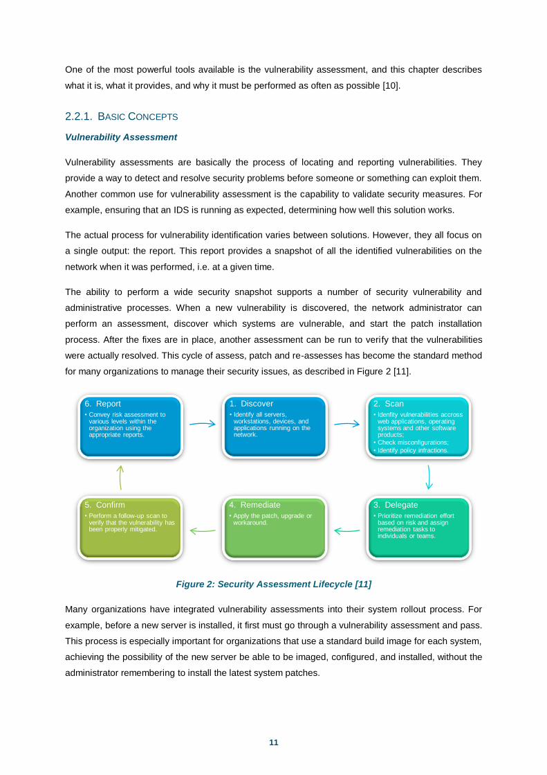
were actually resolved. This cycle of assess, patch and re-assesses has become the standard method
for many organizations to manage their security issues, as described in Figure 2 [11].
Figure 2: Security Assessment Lifecycle [11]
Many organizations have integrated vulnerability assessments into their system rollout process. For
example, before a new server is installed, it first must go through a vulnerability assessment and pass.
This process is especially important for organizations that use a standard build image for each system,
achieving the possibility of the new server be able to be imaged, configured, and installed, without the
administrator remembering to install the latest system patches.
1. Discover
• Identify all servers, workstations, devices, and applications running on the network.
2. Scan
• Idenfity vulnerabilities accross web applications, operating systems and other software products;
• Check misconfigurations;
• Identify policy infractions.
3. Delegate
• Prioritize remediation effort based on risk and assign remediation tasks to individuals or teams.
4. Remediate
• Apply the patch, upgrade or workaround.
5. Confirm
• Perform a follow-up scan to verify that the vulnerability has been properly mitigated.
6. Report
• Convey risk assessment to various levels within the organization using the appropriate reports.

12
Additionally, many vulnerabilities can only be resolved through manual configuration changes. Even
an automated patch installation might not be enough to secure a newly imaged system. It’s much
easier and strongly recommended performing a vulnerability assessment to find these problems at
build time, when configuration changes are simple and risk-free, than after the deployment of the
system.
Although the primary purpose of an assessment is to detect vulnerabilities, the assessment report can
also be used as an inventory of the systems on the network and the services they expose. Since
enumerating hosts and services is the first part of any vulnerability assessment, regular assessments
can give a current and very useful understanding of the services offered on the network. Assessments
assist in crises: when a new worm is released, assessment reports are often used to generate task
lists for the system administration staff, allowing them to prevent a worm outbreak before it reaches
critical mass.
Asset classification is one of the most common routines for vulnerability assessment tools. For
instance, knowing how many and what types of printers are in use will help resource planning.
Determining how many Windows systems still need to be upgraded can be as easy as looking at the
latest report. The ability to glance quickly at a document and find out what network resources might be
overtaxed or underutilized can be priceless to topology planning.
Assessment tools are also capable of detecting corporate policy violations. Many tools will report P2P
services, shared directories with illegally-shared copyrighted material, and unauthorized remote
access tools. If a long-time system administrator leaves the company, an assessment tool can be
used to detect that a backdoor was left in the firewall. If bandwidth use suddenly spikes, a vulnerability
assessment can be used to locate workstations that have installed file-sharing software.
Another important use for the vulnerability assessment gathered data is event correlation. If an
intrusion does occur, a recent assessment report allows the security administrator to determine how it
occurred and what other assets might have been compromised. If the intruder gained access to a
network consisting of unpatched web servers, it is safe to assume that he gained access to those
systems as well [10].
2.2.2. VULNERABILITY ASSESSMENTS VS. INTRUSION DETECTION SYSTEMS
The difference between vulnerability assessments and IDSs is not always immediately clear. To
understand the differences between these complimentary security systems, we need to understand
how an IDS works.
When people speak of IDS, they are often referring to what is more specifically called a Network
Intrusion Detection System (NIDS). The NIDS role is to monitor all network traffic, pick out malicious
attacks from the normal data, and send out alerts when an attack is detected. This malicious activity
includes DoS (Denial of Service) attacks, port scans, or even attempts to crack into computers.

13
Connected to a hub, network switch or tap, a NIDS works by reading all the incoming packets and
trying to find suspicious patterns. If, for example, a large number of TCP connection requests to a very
large number of different ports are observed, one could assume that there is someone committing a
port scan at some of the network components. On the other hand, a NIDS is not limited to inspect
incoming network traffic only. Often, valuable information about an ongoing intrusion can be learned
from outgoing or local traffic as well. Some attacks might even be staged from the inside of the
monitored network and therefore not regarded as incoming traffic at all. An example of a NIDS is
Snort.
This type of defense is known as a reactive security measure, as it can only provide information after
an attack has occurred. In contrast, a vulnerability assessment can provide data about a vulnerability
before it is used to compromise the system, allowing security administrators to prevent the intrusion.
For this reason, vulnerability assessments are considered a proactive security measure.
2.2.3. ASSESSMENT TOOLS
The first experience that many people have with vulnerability evaluation is by seeking advice from a
security consulting firm to provide a network audit, accepting its wisdom. This type of audit is normally
comprised of both manual and automated components. The auditors often use automated tools for
much of the initial groundwork and follow it up with manual system inspection to provide careful
results. Another way to obtain the same results is accomplished by simply using an automated
assessment tool to perform the process in-house.
The need for automated assessment tools has resulted in a number of advanced solutions being
developed. These solutions range from simple graphical user interface (GUI) software products to
stand-alone appliances that are capable of being linked into massive distributed assessment
architectures. Due to the overwhelming number of vulnerability tests, the commercial market is easily
divided between a few well-funded independent products and literally hundreds of solutions built on
vulnerability scanners such as Nessus [12], Nikto [13], or MBSA [14] from Microsoft.
Nessus
Nessus [12] is a vulnerability assessment solution that can perform many automated tests against a
target network, including:
ICMP, TCP, and UDP scanning;
Testing of specific network services (such as Apache, MySQL, Oracle, Microsoft IIS, etc.);
Configuration auditing;
Asset profiling;
Rich reporting of vulnerabilities identified.
Nessus scans can be distributed throughout an entire enterprise, inside De-Militarized Zones (DMZs),
and across physically separate networks. All of the world’s largest penetration testing providers and
security consultants use Nessus to perform bulk network scanning and assessment.
14
Nessus has two components: a server (daemon), which does the scanning; and a client, which
controls scans and presents the vulnerability results to the user. Nessus reporting is comprehensive in
most cases. However, reports often contain a number of false positives and a lot of noise (as issues
are often not reported concisely or different iterations of the same issue are reported), so it is
important that consultants manually parse Nessus output, perform qualification, and produce an
accurate and concise handwritten report. As with many other tools, Nessus uses Common
Vulnerabilities and Exposures (CVE) references to report issues. CVE is a detailed list of common
vulnerabilities maintained by the MITRE.
Nessus can be run under Linux, Solaris, Windows, Mac OS X, and other platforms. Tenable Security
maintains a commercially supported and up-to-date branch of Nessus and its scanning scripts, which
has enhanced features relating to SCADA testing and compliance auditing under Windows and UNIX.
Microsoft Baseline Security Analyzer (MBSA)
MBSA [14] is an easy-to-use tool that helps small and medium businesses determine their security
state in accordance with Microsoft security recommendations and offers specific remediation
guidance. It improves the security management process detecting common security misconfigurations
and missing security updates on networked computer systems.
Built on the Windows Update Agent and Microsoft Update infrastructure, MBSA ensures consistency
with other Microsoft management products including Microsoft Update (MU), Windows Server Update
Services (WSUS), Systems Management Server (SMS) and Microsoft Operations Manager (MOM).
Used by many leading third party security vendors including Tivoli [15], Patchlink and Citadel, MBSA
on average scans over 3 million computers each week [14].
Commercial Network Scanning Tools
Commercial scanning packages are used by many network administrators and those responsible for
the security of large networks. Although not cheap (with software licenses often in the magnitude of
tens of thousands of dollars [2]), commercial systems are supported and maintained by the respective
vendor, so vulnerability databases or further program items are kept up-to-date. With this level of
professional support, a network administrator can assure the security of his network to a certain level.
Some other recognized commercial vulnerability assessment solutions consist of:
ISS Internet Scanner [16]
eEye Retina [17]
QualysGuard [18]
Matta Colossus [19]
Again, an issue with such automated vulnerability assessment packages is that they increasingly
record false positive results. As with Nessus, it is often advisable to use a commercial scanner to
perform an initial bulk scanning and network service assessment of a network, then fully qualify and
investigate vulnerabilities by hand to produce accurate results. Matta Colossus addresses this by
allowing the user to supervise a scan as it is conducted, and also to edit the final report.

15
2.3. MANAGEMENT
In general, network management is a service that employs a variety of tools, applications, and devices
to assist human network managers in monitoring and maintaining networks. This involves a distributed
database, auto polling of network devices, and high-end workstations generating real-time graphical
views of network topology changes and traffic, and refers to the activities, methods, procedures, and
tools that pertain to the operation, administration, maintenance, and provisioning of networked
systems [20]:
Operation deals with keeping the network (and the services that the network provides) up and
running smoothly. It includes monitoring the network to spot problems as soon as possible,
ideally before users are affected;
Administration deals with keeping track of resources in the network and how they are
assigned. It includes all the ―housekeeping‖ that is necessary to keep the network under
control;
Maintenance is concerned with performing repairs and upgrades. For example, when
equipment must be replaced, when a router needs a patch for an operating system image,
when a new switch is added to a network. Maintenance also involves corrective and
preventive measures to make the managed network run better, such as adjusting device
configuration parameters;
Provisioning is concerned with configuring resources in the network to support a given
service. For example, this might include setting up the network so that a new customer can
receive voice service.
2.3.1. BASIC CONCEPTS
Network Management Architecture
Most network management architectures use the same basic structure and set of relationships. End
stations (managed devices), such as computer systems and other network devices, run software tools
(network management agents) that enables them to send alerts when they recognize problems.
Upon receiving these alerts, management entities are programmed to react by executing a sort of
actions, including operator notification, event logging, system shutdown, and automatic attempts at
system repair. Management entities also can poll end stations to check the values of certain variables.
Polling can be automatic or user-initiated, but agents in the managed devices respond to all polls.
Network management agents are software modules that first compile information about the managed
devices in the network which they reside, then store this information in a management database, and
finally provide it (proactively or reactively) to management entities within Network Management
Systems (NMSs) via a network management protocol.

16
Figure 3: Basic Network Management Architecture [21]
Well-known network management protocols include the Simple Network Management Protocol
(SNMP), Common Management Information Protocol (CMIP) [21], and Windows Management
Instrumentation (WMI) [22]. Figure 3 represents the basic network management architecture.
2.3.2. SIMPLE NETWORK MANAGEMENT PROTOCOL (SNMP)
Networks can be monitored and controlled by using the Simple Network Management Protocol
(SNMP). The network administrator usually runs an SNMP network management program, such as
HP OpenView [23], to monitor servers and routers. The NMS has the capability to check the status of
individual network devices.
SNMP runs on a large amount of devices and operating systems, including but not limited to [24]:
Core network devices – routers, switches, hubs, bridges, and wireless network access points;
Operating systems;
Consumer broadband network devices – cable modems and DSL modems;
Consumer electronic devices – cameras and image scanners;
Networked office equipment – printers, copiers, and FAX machines;
Network and systems management frameworks – network sniffers and network analyzers;
Uninterruptible Power Supplies (UPS).
By default, SNMP provides the capability to monitor a device with notification of possible error
conditions, to reconfigure limited system parameters, or to reboot or shutdown the network device.
Even though the version 3 of the protocol (SNMPv3) provides authentication, privacy and access
control, SNMP has an extremely weak security mechanism [25]. As a result of not implementing
encryption, SNMP versions 1 and 2c are subject to packet sniffing of the clear text password (known
as community string) from the network traffic, which symbolize negative security implications.
As a result, a network auditor should be concerned about SNMP being allowed to travel unregulated
across the network, forcing all SNMP managed devices to use unique passwords rather than the
default ones ―public‖ and ―private‖ [26].
AGENT
MANAGEMENT
DATABASE
AGENT
MANAGEMENT
DATABASE
AGENT
MANAGEMENT
DATABASE
NMS
MANAGEMENT
ENTITY
NETWORK
NETWORK
MANAGEMENT
PROTOCOL
MANAGED
DEVICES
MANAGED
DEVICES

17
2.3.3. WINDOWS MANAGEMENT INSTRUMENTATION (WMI)
Windows Management Instrumentation (WMI) [22] is a set of extensions to the Windows Driver Model
(WDM) that provides an operating system interface through which instrumented components provide
information and notification. WMI is Microsoft's implementation of the Web-Based Enterprise
Management (WBEM) and Common Information Model (CIM) standards from the Distributed
Management Task Force (DMTF).
WMI allows scripting languages like VBScript or Windows PowerShell to manage Microsoft Windows
personal computers and servers, both locally and remotely, and is preinstalled in Windows Vista,
Windows Server 2003, Windows XP, Windows Me, and Windows 2000.
The purpose of WMI is to define a non-proprietary set of environment-independent specifications
which allow management information to be shared between management applications. WMI
prescribes enterprise management standards and related technologies that work with existing
management standards, such as Desktop Management Interface (DMI) and SNMP. WMI
complements these other standards by providing a uniform model. This model represents the
managed environment through which management data from any source can be accessed in a
common way.
2.3.4. MANAGEMENT TOOLS
Network management tools come in software suites that offer the following management functions for
the general network resources:
Graphical User Interface (GUI);
Network topology map;
Integration with Database Management Systems (DBMS);
Default network resource query method;
Event Logging.
Table 3 shows a small portion of the existing network management solutions.
Table 3: Examples of Network Management Tools
Tool Type
HP OpenView Network / Systems Management
IBM Tivoli NetView Monitor Program based on SNMP Protocol
Spiceworks Network Monitoring Software for Network Management
AutoScan Network Network Monitoring and Management Tool
Intellipool Network Monitor Network, Server and Performance Monitoring on SNMP enabled devices
System Center Operations Manager Performance and Event Monitoring product from Microsoft
CA Spectrum Network Fault Management
Multi Router Traffic Grapher Free software for Monitoring and Measuring the Traffic Load on network links

18
2.4. SUMMARY
Three related and yet distinct principles that help IT departments manage their software and
equipment were carefully introduced: Network Auditing, Assessment and Management.
If combined and used effectively, these methodologies contribute to assure higher levels of security on
enterprise network systems, and when carefully assembled with an assortment of network scanning
methods and algorithms, achieve a comprehensive network description, through efficient and accurate
techniques.

19
3. STATE-OF-THE-ART
3.1. NETWORK DISCOVERY
Since ―You can’t manage what you can’t see‖ [27] and as previously stated, network discovery is one
of the main components considered necessary to accomplish or analyze the security state of any
enterprise network.
It can be essentially described as the process to scan any network to create an accessible inventory
as well as present a visual topology containing all of its active network devices and systems.
Implementing a full IP address and host fingerprinting detection accurately discovers and maps:
Gateways and hosts;
Machine names;
Common open ports;
Operating systems for each host discovered;
Private networks;
Access points to the discovered networks.
Additionally, this identifies devices that the network administrator did not know were on the network,
including hosts that may have been maliciously or accidentally placed.
To use the discovery service, the administrator generally submits a few DNS information or a set of IP
address ranges to find computers within those domains or address collection [28]. Despite helping to
locate devices outside the DNS record and to bypass firewall rules or router ACLs, a recurring
challenge seems to arise when assessing organizations with an assorted allocation of IP addresses.
Various approaches have been described in the literature for discovering network topology. Generally,
they are based on SNMP and either active probing or passive monitoring methods [29]. Additional and
related terminology is evaluated as follows.
3.1.1. AUTO DISCOVERY
―Auto Discovery‖ is a term that defines a methodology for network discovery that will automatically and
efficiently identify which network assets are alive, basing on the information available by specific
network equipment (e.g. routers or gateways) or by taking advantage of particular network protocols.
SNMP
One effective way to perform an automatic discovery of network topology is by using SNMP, assuming
that the protocol is available everywhere in the network. The first router added to a temporary set list is
the discovery node's default gateway. For each router in the list, neighboring routers are found from
that router’s Routing table and hosts are obtained from its ARP table. This information helps to enlarge
and improve the identified IP address list, the discovery of different connection paths, and the creation
of a diagram of external links to routers, firewalls, gateways, etc.

20
Several approaches to finding layer-3 (IP network) topologies have been proposed [30] [31] [32]. One
approach uses pattern matching on interface counters available through SNMP [33].
Although standard SNMP MIB information is widely supported in modern IP networks, requiring no
modifications to the operating system software running on elements or hosts [34], recognizing the
importance of layer-2 topology, a number of vendors have recently developed proprietary tools and
protocols for discovering physical network connectivity. Examples of such systems include Cisco’s
Discovery Protocol [35] and Nortel Networks’ Enterprise Network Management System [36].
Another approach finds the topology based on tables for the spanning tree algorithm available through
SNMP [37], and a different algorithm shapes the concept of operational topology and a technique for
discovering an IP network. The algorithm is dynamic, constantly evolving and discovering new nodes,
edges and paths as they are exercised, including the usage pattern of paths between endpoints [38].
A different algorithm once more requires the installation of SNMP agents on routers, switches and
network printers [39]. The ARP cache of the routers is obtained via SNMP and then an ICMP request /
response mechanism is used to discover the network. This technique enables network administrators
to run on the network, after installation of SNMP on routers, switches and network printers. The goal is
to automatically discover network topology in an efficient manner.
There are, however, many situations where SNMP cannot be used. Despite being a well-known
protocol, commonly used on enterprise network routers and switches, SNMP isn’t largely used in
workstations and servers. At the same time, since no network device will have an ARP or Routing
entry for all the devices in the network, all other IP addresses (not acquired through SNMP) cannot be
ignored. As this is true, most solutions to IP network topology discovery require SNMP to be installed
on nearly all network elements for an accurate topology discovery. The problem is that, for security
reasons, access to SNMP can easily be turned off by many network administrators, and enabling it
can be a very time consuming task as it requires manual intervention. A remaining weakness is that,
for much information a specified host owns (e.g. from ARP or Routing tables), it is stored for a short
period of time and can be lost or outdated before being captured [25].
Relying on SNMP, some tools available in the market that can be used for monitoring the network and
particularly for discovering the network topology include InterMapper [40], LAN Surveyor [41],
SolarWinds [42], or NetworkView [43]. Also, many recognized common network management tools,
such as HP OpenView [23] and IBM Tivoli [15] are based on closed proprietary SNMP technology.
Zone Transfer from a DNS Server
A Domain Name Server keeps a binding from every name in the domain to its IP address. Most DNS
servers respond to a ―zone transfer‖ command by returning a list of every name in the domain. Thus, a
DNS zone transfer is useful in finding all hosts and routers within a domain. This technique has low
overhead, is fast, and accurate. Nevertheless, network managers frequently disable DNS zone
transfer due to security concerns [30].

21
3.1.2. ACTIVE PROBING
Active probing finds active network resources by mutually sending packets to them as well as
analyzing its response. We present several related tools and scanning techniques, which give support
to network discovery [44].
Ping Scan
Generally, every IP host is required to echo an ICMP Ping packet back to its source. The ping tool
therefore should accurately indicate whether the pinged machine is active or not. With suitably small
packets, ping also has a low overhead. As pings to live hosts succeed within a single round-trip time,
which is a few tens of milliseconds, the tool is fast. Pings to dead or non-existent hosts, however,
timeout after a conservative interval of 20 seconds, so pings to such hosts are expensive.
The Ping Scan technique consists in sending ICMP echo request packets sequentially to every IP
address on the network, relying on the response of each active device with an ICMP echo reply.
The intrinsic problem is that blocking ICMP sweeps is rather easy, simply by not allowing ICMP echo
requests into the network from the void. Additionally, both firewalls and IDSs can be configured to
detect and therefore block sequential pings [30].
TCP / UDP Scans
As earlier acknowledged, some active network resources running network services may not react to
ICMP echo requests. Given this point of view, instead of directly looking for the existence of network
devices, it is possible to search for open ports, identifying public services being executed. If a
response is received from a remote device, we can safely identify it as active.
Nonetheless, because results can be affected by firewalls or host countermeasures, in order to
accurately identify available devices on the network, each address is supposed to be scanned by
probing all target ports, with the intent to identify which services are running. In any case, it should be
trustworthy to focus the discovery on a set of standard TCP or UDP service ports, 21 (FTP), 22 (SSH),
23 (Telnet), 80 (WWW), 135 (DCOM Service Control Manager), 161 (SNMP) and 445 (Microsoft
Directory Services), hoping to rarely be filtered [45].
ARP Scan
Sending a chain of broadcast ARP packets to the local network segment and incrementing the
destination IP address of each packet, is a first-class network discovery technique to find its active
devices. Since every network equipment must answer when its IP address is mentioned on a
broadcast ARP, this technique is supposed to be failure-proof. In contrast to Ping Scan, which
response is optional, network elements must reply to broadcast ARP. Difficult to be blocked, this
technique’s downsides are that it only works for the current local subnet and is easily detected by
sniffers and IDSs.

22
Traceroute
Traceroute discovers the route between a probe point and a destination host by sending packets with
progressively increasing TTLs. On seeing a packet with a zero TTL, routers along the path send ICMP
TTL-expired replies to the sender, which marks these to discover the path.
Traceroute is usually accurate because all routers are required to send the TTL-expired ICMP
message. However, some network administrators are known to hide their routers from traceroute by
manipulating these replies to collapse their internal topology. This reduces both the accuracy and the
completeness of topologies discovered using traceroute. Two probes are sent to every router along
the path, so this tool generates considerably more overhead than ping. Since probes to consecutive
routers are spaced apart to minimize the instant network load, the time to complete a traceroute is
also much longer than a ping.
3.1.3. SMART ACTIVE PROBING
Because of the large number of possible IP addresses, sending separate probe requests to each and
every one is not feasible in determining the devices that are alive in the network. Therefore, it is
important to dynamically decide the probability that a certain network address has to be alive.
Stipulating that this value is considerably low, and to generate a quick initial response to the network
discovery process, the device won’t be initially probed.
An intelligent and efficient algorithm for generating a list of IP addresses having a high probability of
being assigned to devices in the network is proposed, adding the capability to analyze its dynamic
performance and amending its functionality to generate better response [39]. This algorithm has been
evaluated, implemented, and extensively tested in the research labs at NUST Institute of Information
Technology, Pakistan. The authors proposed an intelligent algorithm that requires installation of SNMP
on the routers, switches and network printers. They retrieve the ARP cache of the routers via SNMP
and then use ICMP request/response mechanism to discover the network. Figure 4 shows the
comparison between the results in terms of time and number of hosts found. Figure 5 shows the
comparison between the results in terms of initial accuracy.
Figure 4: Comparison of Number of Hosts
Found and Time Consumed [39]
Figure 5: Comparison of Initial Accuracy [39]

23
The authors evaluated the tests with a different set of parameters, and describe the results as follows:
From Figure 4 it can be seen that Test A has a very steep but short slope, giving quick initial
response. The reason for such a behavior is that the intelligent algorithms have skipped a lot
of IP addresses. It quickly found the hosts whose IP addresses were in sequence or grouped
together, and then skipped most of the IP addresses, causing the high miss percentage. It
queried a total of 901 IP addresses;
Test B was the longest test. Initially there is a steep curve but not as steep as test A, C or D.
This is because it skipped less IP addresses and the next sequence of IP addresses were not
quickly reached (due to timeouts). Then in the middle stage there is a sudden rise as it found
the next sequence of IP addresses. Then the slope becomes almost horizontal at the later
stage because it was running for IP addresses that had not been assigned to any host. It had
97 percent initial accuracy because it skipped few IP addresses and queried about 38000 IP
addresses;
Tests C and D have quicker initial response. They maintain a good trade-off between
accuracy and initial response. Tests C and D queried 7149 and 7214 IP addresses,
respectively.
Figure 5 shows that tests C and D discovered more than 70 percent of the network in about 15
minutes.
Even though the different scan parameters have not been described at this point, it’s simple to
perceive that intelligent algorithms to determine the IP ranges which have greater probability of being
assigned an IP address are confirmed to reduce the number of queries required to discover the
devices in the network, with the special characteristic that the discovery process yields a quick initial
response.
Another considered approach compares two algorithms: using evenly spaced IP addresses from the
IP address space as targets for probes, and a variation of the informed random address probing
heuristic that randomly selects prefixes for probing, instead of using the arbitrary selection algorithm
[46].
3.1.4. PASSIVE MONITORING
The discovery of network elements through Passive Monitoring primarily involves the employment of
packet sniffers, special programs that capture all network traffic. These tools are useful to identify
network elements that do not react to any of the previous mentioned techniques, and even to intercept
confidential data such as passwords (e.g. community strings) or access codes, often valuable to the
scanning process.
The natural disadvantage of this procedure is, due to fact that being passive, it fundamentally depends
on the existence of network traffic through the connected devices in order to be accurate and efficient.
In any case, as every address is captured, some additional work to filter external network addresses is
required, which can possibly be inaccurate if the local network address range is unknown.

24
Finally, since even with an uninterrupted sniffing the process can take several hours or days to detect
every active machine on the network, this technique should cover a complementary practice in order
to discover a number of elements earlier undetected.
3.1.5. NETWORK SCANNING TOOLS
Nowadays, there are a numerous network scanning tools, each one with its own characteristics,
advantages, and disadvantages. Some of these scanning methods are simple to understand and
execute, while others are more complex and require some additional groundwork and configuration
before the scan can begin.
Network Mapper (Nmap)
Nmap [47] is a port scanner used to scan large networks and perform low-level ICMP, TCP, and UDP
analysis. It offers a number of advanced features such as service protocol and IP fingerprinting,
stealth scanning and low-level network traffic filter analysis, and can be run under most operating
platforms including Windows, Linux and Mac OS X. Most importantly, Nmap supports the following
scanning techniques [48]:
TCP SYN Scan;
TCP Connect;
FIN Scan;
Xmas Tree Scan;
Null Scan;
Ping Scan;
Version Detection;
UDP Scan;
IP Protocol Scan;
ACK Scan;
Window Scan;
RPC Scan;
List Scan;
Idle Scan;
FTP Bounce Attack.
The term ―ping‖ was previously considered as a reference to an ICMP echo request and the
corresponding ICMP echo reply. However, Nmap’s use of the word ―ping‖ is more generic. In the
Nmap world, a ping is any request that would prompt a remote station for a response.
The tool offers a wide variety of very flexible options to modify the techniques used, allowing
customization on every aspect of the discovery. Consequently, to maximize the possibility of locating a
device through Firewalls, Routers, IDSs or Packet Filters, the user is able to choose several options
that can be combined together to an accurate network discovery. These ping scan (host discovery)
alternatives are subsequently listed [48]:
ARP Ping;
ICMP Echo Request Ping;
TCP ACK Ping;
TCP SYN Ping;
UDP Ping;
ICMP Timestamp Ping;
ICMP Address Mask Ping
Once a response is received from a remote device, Nmap identifies it as active on the network and
begins scanning it for detailed port information.

25
SuperScan
SuperScan [49] is a graphical tool from Foundstone that runs on Microsoft Windows operating
systems. It is very fast and can be used for enumeration, port scanning, and banner grabbing, and can
produce a good HTML report. Foundstone notes that Windows XP Service Pack 2 limits access to raw
ports and requires administrator privileges to run.
SolarWinds
The company SolarWinds offers many commercial applications. The SolarWinds Toolset [42] contains
many useful tools for network, system, and security administrators. For SNMP scanning, the tool IP
Network Browser is available in all of SolarWinds toolkit offerings and is a nice, fast SNMP scan tool. It
allows the input of multiple targets as well as multiple community strings. As the scan progresses, the
results are instantly updated and drill down as each host is finished.
AutoScan Network
AutoScan [50] is a free application designed to explore and to manage a network. Entire subnets can
be scanned simultaneously without human intervention. The objective of the program is to list all
equipments connected to the network, including a list of open ports per equipment. It consists of:
Automatic network discovery;
Detection of the OS, brand and model known;
Ability to save the network state;
A Samba share browser;
A Nessus client.
NetSNMP
Net-SNMP [51] is a suite of applications used to implement SNMP. These tools work on most
operating systems while its functionality may not be the same on each one. The tool snmpget
downloads the SNMP information from a single machine, and snmpwalk traverses multiple machines.
3.2. SECURITY MANAGEMENT
As earlier acknowledged, security in computing is continually a problem both technical and social [52]:
It’s a technical problem as the large amount of hardware architectures, operating systems
versions, application protocols and requirements, imply that the definition or implementation of
security policies in distributed systems is difficult to realize and maintain;
It’s a social problem because the vast majority of computer system users and small domestic
companies are normally not aware of the safety problems that may affect their regular
activities and neither on how they should deal with them.

26
To complete this framework, there are several factors that contribute to poor security management
processes. Most users employ COTS (Commercial off the Shelf) operating systems, which normally
support the ease of use at the expense of safety. Because safety is uncomfortable, difficult to
understand and configure, many users are simply not willing to adjust it, or support a system that is
constantly placing obstacles. Thus, systems that are conducive to ease typically have to lighten up
security policies and mechanisms to interfere as slight as possible with the typical user’s activity.
Currently there are already some attempts to automatically install and configure some security
policies, which, in most cases, do not properly act in response to the system’s needs, also proving to
be inadequate or excessive.
According to the SANS Institute, the average time of survival of a computer, connected to the Internet
and without special protections, measured as the average time between communications of attacks
and commitments, it's usually the order of a few tens of minutes [53].
An efficient and systematic examination of an information system or application is then needed to
determine the adequacy of security controls, identify security deficiencies, and provide enough
information to predict the effectiveness of the proposed security controls.
3.2.1. CONFIGURING VULNERABILITY SCANS
Vulnerability scanners discover only well-known vulnerabilities. Each vulnerability scanner has a
database of known vulnerabilities. By default, it scans for IP addresses that will respond to a ping and
then looks for the open ports on those addresses. For each port, the scan tool knows what the
common services are. For each common service that runs on that port, it will start scanning for known
vulnerabilities. The inherent problem is: how to properly configure a scan as such?
These tools should not run in their default state. They should always be configured based on the
known variables of the network being scanned along with each target’s device type. By properly
configuring these tools by means of feeding the output of tools designed for enumeration or network
discovery into the scan configuration, the amount of time they take to run can be significantly reduced.
For instance, turning off AIX scans for a Microsoft Windows asset will lower the number of tests
required, and consequently the assessment duration.
Figure 6: Vulnerability Scanners Performance Tests [54]

27
Figure 6 [54] presents some performance tests results conducted to six known vulnerability scanner
applications. As an example, NetRecon took 20 hours to complete a vulnerability analysis to 800
network machines. Almost certainly, the test was not properly configured.
3.3. HOST DISCOVERY PROBLEMS
Different IP network scanning methods to identify live hosts allow the testing and an effective detection
of vulnerable network components. Nevertheless, there are several related problems that must be
solved or circumvented in the final implemented solution.
3.3.1. COUNTERMEASURES
As efficiency and accuracy are essential requirements to accomplish a practical network discovery, it’s
important to find all the accessible network resources through the smallest amount of time and
disturbance in the infrastructure. However, there are several countermeasures to employ as
considering technical modifications to networks and filtering devices to reduce the effectiveness of
network scanning and probing undertaken by attackers. These protections include [2]:
Filter inbound ICMP message types at border routers and firewalls. This forces attackers to
use complete TCP port scans against all of IP addresses to map the network correctly;
Filter all outbound ICMP type 3 ―unreachable‖ messages at border routers and firewalls to
prevent UDP port scanning and firewalking from being effective;
Configuring Internet firewalls so that they can identify port scans and throttle the connections
accordingly. However, this functionality can be abused by attackers using spoofed source
addresses, resulting in DoS;
Ensure that routing and filtering mechanisms (both firewalls and routers) can’t be bypassed
using specific source ports or source routing techniques;
Ensure that firewalls aren’t vulnerable to stateful circumvention attacks relating to malformed
PORT and PASV commands;
Ensure that the latest service pack is installed;
Investigate using reverse proxy servers in the environment if a high-level of security is
required. A reverse proxy will not forward fragmented or malformed packets to the target
systems, so a number of low-level attacks are blocked (check Figure 7 [55]);
Be aware of the network configuration and its publicly accessible ports by launching TCP and
UDP port scans along with ICMP probes against the IP address space. It is surprising how
many large companies still don’t properly undertake even simple port scanning exercises.
As a result, in order to be precise, the scanner is required to intelligently utilize every possible method
to discover which systems are alive, for the reason that when used independently, scanning
techniques such as Ping Sweeps, TCP/UDP and ARP Scans, as well as SNMP-based algorithms, all
have their own drawbacks.

28
Figure 7: Reverse Proxy Server Operation [55]
3.3.2. IMMENSE ADDRESS SPACE
Some may declare that unless performing a scan on every possible IP address and port combination,
the scanning isn’t being thorough enough. In order to be complete, one must perform a scan as
stated. Although correct, performing such a scan usually takes a considerable amount of time and is
not feasible in determining which devices are alive because of the large number of possible IP
addresses and port arrangements. For example, there will be more than 16 million possible addresses
for Class A networks and 65,535 possible open ports for every address.
In fact, a fundamental and yet complex dilemma on the subject of network discovery is about defining
and evaluating a balance between the pros and cons of every scanning technique. If being absolutely
thorough, and both time and topology discovery are of no consideration, a blind scan on all IP
addresses is recommended. On the contrary, in order to build an accurate and efficient network
topology discovery system, not only intelligent algorithms must be applied to skip unused addresses,
but also different discovery schemes should be combined.
3.3.3. INPUT INFORMATION REQUIRED
In addition to the exact administration credentials, many network scanners available on the market
generally require the administrator to submit a few DNS information or a set of IP address ranges to
find computers within those domains or address collection, by means of pinging that range and
evaluating the answer to discover the active devices. Normally, it’s possible to input an IP range (such
as 192.168.113.1-10 or 192.168.1.0/24) or an IP address list (separated IP address values).
Despite helping to locate devices outside the DNS record and to bypass Firewall rules or Router
ACLs, a recurring challenge seems to arise when assessing organizations with a large allocation of IP
addresses. To build an innovative and automated network discovery tool, it’s significant to make as
few assumptions as possible about the network, adding the improvement and intention of not requiring
an IP address range as input or any other privileges.

29
3.4. NETWORK TOPOLOGY DISCOVERY
The first step for integrating and automating related infrastructure management disciplines and
processes that are loaded by disparate and incompatible tools is to gain an accurate, complete, and
up-to-date picture of the network infrastructure.
In the typical organization, the complexity and dynamic nature of the distributed environment make it
difficult to sustain visibility into assets and even more complex to determine their interrelationships.
Manual discovery of the environment is possible, but very cumbersome, costly, and risky.
Organizations require this level of discovery and need to automate the process as much as possible.
In an attempt to solve the problem, many organizations have deployed automated discovery tools that
have the ability to discover assets, as well as application dependency mapping products that attempt
to document relationships between IT components and business services. Most tools, however, are
limited in scope and reveal only a part of the total environment. To expand their view, organizations
have deployed multiple tools from multiple vendors, resulting in fragmentation of data across multiple,
incompatible, and often conflicting data stores.
Virtually all existing network topology discovery tools use the earlier described network management
paradigm. That is, distributed agents are deployed on managed devices to collect local information
and report it back to some management unit. Those that use standard protocols such as SNMP fall
into this model too.
To discover network topology by taking advantage of SNMP, the algorithm is based on the information
stored in the router’s Routing or ARP tables: the Routing table contains information used for internet
routing and can be used to derive network topology; to discover the connectivity of other hosts, a
router’s ARP table is used. This scheme continues in a recursive manner across the entire network.
Topology discovery via SNMP offers the benefit of interoperatability among devices from different
vendors, as well as efficiency and accuracy on networks that have SNMP enabled. Conversely, this is
just the problem. To accurately perform a network topology discovery, we cannot assume that SNMP
is globally deployed on network environment, or the community string is either predictable or known.
3.5. SUMMARY
Without full visibility of what’s happening on a network, all organizations are exposed to unnecessary
costs and risks. A network discovery process easily helps network managers to submit scan reports to
the administration and to determine the network perimeter. It also identifies devices that the network
administrator did not know were on the network, including maliciously or accidentally placed hosts,
assisting the system administrators in securing their information systems. However, current
proceedings rely on the fact that SNMP is universally deployed, particularly at end-systems, or that the
discovery tool is allowed to have administrative privileges, also requiring much preliminary user
intervention.

30
Vulnerability scans identify vulnerabilities, categorize the risks, and then provide solutions or
recommendations. A powerful, up-to-date and easy-to-use remote security scan tool ensures that web
sites, servers, routers, firewalls and other network connected devices are free of known vulnerabilities.
Nevertheless, just before running a vulnerability scan to a prearranged IP address collection, the
achievement of a complete network discovery process is truly significant. This practice not only
provides the vulnerability scan the proper target address collection, but also categorizes every IP
enabled device, including routers, computers, switches (both managed and unmanaged) and network
printers, this way managing different tests for each grouping, and consequently producing more
efficient results.
These situations clearly persuade the development of effective, intelligent and general-purpose
algorithmic solutions for automatically discovering the current physical topology of an IP network to
assess its security state, also intending to oppose or contradict the previously acknowledged network
scan countermeasures.

31
4. PROPOSAL
The proposed solution to the stated problems is the implementation of a genuine, intelligent and
automated network discovery and vulnerability evaluation framework. The implementation is neither
simple nor straightforward. Therefore, a series of successive steps must be taken in order to ensure
its suitability. The suggested architecture to achieve the expected results is depicted in Figure 8.
Figure 8: Proposed Framework Architecture
4.1. INTELLIGENT NETWORK DISCOVERY
For an accurate topology discovery, almost all the existing solutions require the configuration of
agents on nearly all network devices, a requirement only feasible within a network management
approach. In practice, additional algorithms have been designed to either perform in a predefined or
predicted manner, otherwise providing evidence to be ineffective at all [25].
Integrating different host scanning techniques, applying and improving the intelligence of the existing
discovery algorithms, and employing the available information from the protocols and configurations
used while making as few assumptions as possible about the network, is the indispensable work to
build a genuine, intelligent and automated network discovery framework.
4.1.1. EFFICIENCY & INTELLIGENCE
Nearly all corporate networks have a common and overwhelming goal. They aim to provide the
maximum quality of service while maintaining the maximum amount of uptime. Thus, if the scanning
method is aggressive with a low amount of latency, there’s a possibility of downtime due to services
crashing, systems not responding, or bandwidth exceeding the capacity of the network.
CMDB Integration & Reporting
3
Customized Vulnerability
Scans
2
DeviceType Ckecks
1
Intelligent Network
Discovery

32
Distributed Scan
When performing a penetration testing or a commercial security auditing, one significant objective is to
identify security risks without being noticed by the rest of the organization. To prevail over this issue,
only the smallest possible network packets with just a couple of frames are sent into the network, as
well as the infrequent opening of application sessions to ensure the art of misdirection.
As a result, by blending into the environment, nobody will ever know the scan is being processed. The
distributed scan option provides this level of cover by looking at the IP address pool to be scanned
and mixing them up. Most enterprise management systems poll devices in order, from highest to
lowest. As Figure 9 [56] illustrates, instead of scanning through the list of IP addresses on a subnet in
numerical order, the list is completely rearranged. There’s no way to know which IP address will be
next. Subsequently, when examining a trace file of network traffic, the proposed option makes it
difficult to see a pattern, thus revealing to be merely impossible to fall into a trap.
Figure 9: Traditional Scans versus Distributed Scans [56]
No Input Information Required
Our network discovery system may operate by querying only the local IP subnet to which it is
attached, receive a manual list of IP addresses and IP subnets against which to operate, but most
importantly and innovative, start by querying the local IP subnet to which it is connected and then
query remote IP subnets after learning about their existence using assembled information from local
routers or other elements on the local IP subnet.
Evidently, in order to present the most complete and efficient network coverage, the network
administrator should always provide as input all the network information he knows, including
accessible network credentials or community strings, host addresses, ranges, and subnet prefixes.
The problem occurs when assessing organizations with a large or unknown assortment of addresses.
The input information can easily ignore those devices that the administrator did not know were on the
network, including maliciously or accidentally placed hosts.
Even though, the proposed approach does not force any network information at input. A preliminary
inventory straightforwardly contains the entire discovery device’s available information, including
predictable addresses, subnet masks and ARP cache, as well as identified gateways and servers to
recursively query those devices for liveliness.

33
Intelligent Address Miss
Sending requests to inactive hosts can waste considerable amount of time in the discovery process.
We propose the implementation of an algorithm that queries hosts having higher probability of being
active, leaving out a brute force evaluation of every possible IP addresses. The algorithm is self
learning in the sense that it learns and decides for itself which ranges of IP addresses to send
requests that yield a quick initial response. The efficiency of the algorithm is greatly improved as it
analyzes its performance and automatically amends its functionality.
Because no network device will have entries of all the devices in the network, the proposed solution
cannot ignore the other IP addresses. To accomplish a complete discovery, other process is
responsible for querying the remaining addresses to determine their availability. This is called the
Completion Phase, and runs after the algorithm has been performed.
At this point, the advantage of our proposal is that it yields a quick initial response that tries to discover
the largest network segment possible (assuming efficiency) and then a complete and comprehensive
discovery (guaranteeing accuracy).
4.1.2. ACCURACY
As already mentioned, to get the most recent network mapping, our solution assures that the most
advanced techniques are assembled and used in order to oppose and contradict the main
countermeasures system administrators can configure on the network. Therefore, in order to ensure
correctness and oppose an incomplete discovery, we propose to assemble two auto discovery
methods (SNMP and WMI), several active probing techniques, and a passive monitoring approach to
accomplish a scan as stated.
Auto Discovery Method
A network auto discovery technique may, by itself, assure the network discovery process. The
problem is the impossibility to have the guarantee that the particular protocol that permits the process
will be globally available through the network.
If, for instance, no SNMP enabled device contains information about a given network segment, the
process immediately turns to be inaccurate, omitting the great majority of any specific subnets or
connected devices. As well, as all the network information obtained only persists for a limited period of
time, the accuracy of the procedure cannot be assured on that specified moment. As this is true, the
auto discovery techniques cannot be exclusively used to resolve these natural problems. Despite
being the fastest technique (when globally available), other methods must also be employed to
support the performing of an accurate network discovery process.

34
Active Probing Techniques
Active probing is a technique that uses stimuli (packets) in order to provoke a reaction from network
elements. According to responses, or lack thereof, received from the queried network elements,
knowledge about a network and its elements is gathered.
The information an active network discovery system attempts to collect may include the following:
Inventory of network elements and some of their properties;
Information on network services and their version;
Topology related information;
Vulnerability analysis related information.
An active network discovery system detects network elements that are operational on a network at the
time of the discovery only if the packets sent are able to reach the probed elements and the probed
elements answer the sent query type.
Network obstacles, such as network firewalls, host-based firewalls, load balancers, NAT devices, etc.
prevent probe packets from reaching their target network elements. This results in those network
devices being undiscovered and the results of the active network discovery to be incomplete.
A good example is Microsoft Windows XP SP2, where a host-based firewall is installed by default. The
presence of hosts running Microsoft Windows XP SP2 having their host-based firewall enabled cannot
be discovered by a simple active probing network discovery system. The trend of including a host-
based firewall as part of an operating system installation is not limited to the newest Microsoft
Windows operating systems, but is found as part of other operating systems, such as FreeBSD and
other Linux distributions, Mac OS, and so on.
In order to assure the highest level of accuracy, various host detection techniques and network
protocols must then be used hoping to prevail over these challenging countermeasures.
Passive Monitoring Approach
Theoretically, the usage of a passive network discovery system has zero impact on the performance
of the monitored network. This is due to the fact that the monitored network traffic is copied and fed
into the passive network discovery system. Its operation does not involve actively querying elements
residing on the monitored network in order to gather information about them, about the network, or
other elements. In fact, for the reason that a passive network discovery system does not send any
packets to the network and does not pose a risk to the stability of a monitored network, it can
hypothetically be installed on any network.
A passive network discovery system is able to detect active network elements, which operate behind
network ―obstacles‖ such as firewalls, and send or receive network traffic over the monitored network.
The information collected by these systems might be used for the following purposes:

35
Building the Layer 3 based topology of a monitored network;
Auditing;
Providing network utilization information;
Performing network forensics;
Performing vulnerability discovery;
Creating a context regarding the network operation;
Feeding information collected from a monitored network into other security and/or network
management systems in order to enhance their operation by allowing them to have some
context regarding the network they operate in (information about the network, such as SNMP
community strings, or additional properties).
4.1.3. SMART TOPOLOGY DISCOVERY
Network management protocols should be used to carry out an efficient and hopefully accurate
network topology discovery. As earlier stated, because these protocols are not assured to perform
complete network coverage, other methods must be proposed to complement the former.
A customized Traceroute tool is proposed to bypass gateways that block traditional traceroute packets
or further specified protocols. It provides the functionality of the standard traceroute utility and allows
the trace to be performed over any port.
We propose three different protocols to perform a custom trace over the network: ICMP (the default
method the Internet Protocols suggest to do a trace), UDP and TCP [57]. Normally an ICMP trace will
do the work. But it is possible that ICMP does not show the real picture: routers can use different
priorities or security measures for different types of traffic. So a UDP or a TCP trace can reveal a more
realistic picture.
Another proposed intelligent approach that improves efficiency is the trace path predictability. At the
same time as the physical network topology begins to come together, it is possible to guess the
gateway of several active IP addresses. If, for instance, the host 10.0.1.53 has 10.0.1.254 as its
gateway, we can confidently predict that all the hosts from 10.0.1.54 to 10.0.1.253 will also have the
same gateway. In consequence, this process’ duration is clearly improved.
4.2. DEVICE TYPE CHECKS
After acquiring the status of all network assets, their types may be determined. This process should
use a Port Scanning and Operating System Detection engines to every IP address resolved,
determining its device type (i.e. gateway, host, etc.) and port status. Depending on the device type of
the given address, another procedure will be responsible for running a variety of security and
vulnerability tests.

36
4.2.1. PORT SCANNING
This process is designed to search a network host for open ports. This is often used by administrators
to check the security of their networks and by hackers to compromise it.
While some port scanners only scan the most common or most commonly vulnerable port numbers on
a given host, the result of a scan on a port is usually generalized into one of three categories [58]:
Open or Accepted – The host sent a reply indicating that a service is listening on the port;
Closed or Denied or Not Listening – The host sent a reply indicating that connections will be
denied to the port;
Filtered, Dropped or Blocked – There was no reply from the host.
Based on this report, open ports may well present two vulnerabilities of which administrators must be
wary – security and stability concerns associated with the program responsible for delivering the
service, or the operating system that is running on the host. Even as closed ports only present the
latter of the two vulnerabilities that open ports do, blocked ports do not present any reasonable ones.
4.2.2. OS DETECTION / FINGERPRINTING
This process is not a port scan, although it generally works in conjunction with the scanning processes
[48]. The fingerprinting is based on the remote device’s responses when sent a group of very specific
packets. There will be subtle differences in the responses received from different operating systems
under certain circumstances.
If a particular operating system receives a TCP ACK frame to a closed port, it may react differently
than other operating systems receiving the same frame. It’s these minor response variations that allow
detailed ―fingerprints‖ for different operating systems and devices. The process can, as well,
automatically skip tests to closed ports and use some original logic to decide how many retries to
attempt when an answer isn’t received.
Auto configuring the vulnerability scan by means of device type checks that distinguish its operating
system, different tests for each grouping can be managed therefore producing more efficient results.
4.3. CUSTOMIZED VULNERABILITY SCANNER
We propose to extend our network security scanning suite with robust vulnerability scanners well
suited for large enterprise networks. An important requirement is making the impact of scans on
network load to be as insignificant as possible. As stated above, the scanning engine is previously
configured to test only those exploits that match the configuration of the network device. To assure
efficiency, our vulnerability scanner will not test Windows vulnerabilities on a Linux machine, for
instance.

37
The proposed scanning engine references a continuously updated vulnerability knowledgebase that
includes all the well-known network vulnerabilities [59]. The knowledgebase is considered to be the
backbone for a ―hacker’s perspective‖, scanning networks, systems, applications, commercial and
open source operating systems. As vulnerabilities emerge – an average of 25 each week [28] –
signatures should be able to be created and immediately installed in the knowledgebase, ensuring that
users are always testing for the latest vulnerabilities.
Through its nonintrusive and modern scanning techniques, our proposed approach will help network
administrators secure their networks, comply with industry or governmental regulations pertaining to
security and privacy, and achieve peace of mind.
4.4. CMDB INTEGRATION
A Configuration Management Database (CMDB) is a repository of information related to all the
components of an information system [60]. Although repositories similar to CMDBs have been used by
IT departments for many years, the term CMDB stems from the IT Infrastructure Library (ITIL). In the
ITIL context, a CMDB represents the authorized configuration of the significant components of the IT
environment.
A CMDB helps an organization understand the relationships between its components and track their
configuration. The CMDB is a fundamental component of the ITIL framework's Configuration
Management process. CMDB implementations often involve federation, the inclusion of data into the
CMDB from other sources, such as Asset Management, in such a way that the source of the data
retains control of the data [61].
4.4.1. INTEGRATION IMPORTANCE
IT organizations that want to achieve the full business value from Service Management initiatives need
consistent, current, accurate, and secure information. That’s why a CMDB can help them manage
their infrastructure more effectively. A well configured CMDB can easily monitor Configuration Items
(CIs) – their location, status, and relationships to each other – and consolidate unrelated data sets. It
can provide a single source of accurate information about data in the IT environment, network assets
in this case. This heightened level of control is what drives IT staff to implement CMDBs,
strengthening the value of the services they provide to the business.
A CMDB should work in synchronization with ITIL’s best practices for Service Management. The ITIL
standards for Service Management include Service Support and Service Delivery disciplines, which
depend on the process integration and control provided by the CMDB. Any IT organization concerned
about the evolution and maturity of its IT processes need to understand how a CMDB enhances
Service Management objectives.
This way, combining the power of a CMDB with ITIL’s best practices will assure that any organization
achieves more effective and consistent management across all IT services.

38
4.4.2. AUTOMATED ASSET MANAGEMENT
Asset Management contributes to ITIL processes by supporting the identification, status and
verification aspects. If the discovery procedure is not automated, the configuration database will rarely
contain sufficiently accurate information and it is highly unlikely that the data will be the latest.
In a real-life environment, manual entry of configuration data confirms to be unreliable. Populating the
configuration database with the output from automated inventory management software, the system
will provide a regular update on the status of all devices on the network. This means the auditor will
automatically have the information required to evaluate problems efficiently.
4.4.3. IT ASSET MANAGER FROM OUTSYSTEMS
An easy-to-use IT asset management application that automates the inventory of users, all hardware,
software and security updates, providing notifications for low disk space, offline servers, unlicensed or
forbidden applications, and even consents to schedule every assessment, is also attractive to
incorporate into the proposed network discovery and security suite.
Since security updates prevent serious threats to any network, it may be dangerous not having them
installed everywhere. OutSystems IT Asset Manager [62] helps to quickly check whether a specific
update has already been installed in all computers. The biggest advantage is that the proposed IT
Asset Manager solution is built using OutSystems Express Edition, meaning it can be easily
customized to fit the specific needs of any company.
As ITIL has become a standard set of best practices for IT Management, the existing tools that should
support used to be too rigid, too complex, and too expensive. In most IT asset management
applications, users and software are tracked individually. OutSystems IT Asset Manager takes the ITIL
CMDB approach, and besides listing all assets, it also presents the relationships between them.
In its present condition, OutSystems IT Asset Manager’s discovery technique attempts to identify all
hardware and software assets with no need to install any special agent software on remote machines.
The application uses the WMI technology to introspect the entire network, and for each computer
found, the application displays which applications and updates are present and when they were
installed.
In any case, as there is no guarantee that a technology such as WMI is globally accessible on the
network, and since accuracy is one of our main requirements, we propose extending IT Asset
Manager to also include all the previously presented practices, technologies and algorithms.
4.5. REPORTING
The proposed framework should also deliver both technical data and summary data reports that
summarize the security status of the network and each particular device, including specific network
topology and host information, in addition to a list of detected vulnerabilities and open ports.

39
These reports present comprehensive network discovery scan statistics, their duration and
technologies employed, a description of each security risk detected, threat severity, potential
consequences of exposure, regulatory compliance information and links to validated patches and
fixes. Armed with this information, security managers can prioritize where and how to take corrective
action.
The OutSystems platform offers an important advance to present and manipulate these reports by
completely re-engineering the process of developing, deploying, and maintaining enterprise
applications. Additionally, by combining the productivity offered by visual modeling tools with the level
of extensibility and customization found in integration suites or custom development frameworks,
OutSystems helps a diverse range of businesses deliver their applications in weeks, instead of months
or years. These advantages can clearly be applied to our proposal. For instance, at any time it is
possible to export a list of all assets to MS Excel, consenting information manipulation to either create
more complex reports or archive snapshots of the network state.
4.6. SUMMARY
Under this project, it’s essential to develop a framework that enables both topology discovery and the
identification of all of a computer network’s assets on which there is no information given. Additionally,
through a series of probes and tests, the framework is wanted to draw and describe, with the best
possible accuracy, communication infrastructures, existing systems, applications, and vulnerabilities.
The solution must be open and flexible to enable the integration of new probes and tests, as well as
additionally provide a graphical interface to allow the observation, in different levels of detail, the
discovered components and associations between them.
Following what was assumed in section 1.7., our goal is to make use of the best qualities of every type
of tool, while adding some intelligence to what currently exists, in order to cumulatively build a novel
and innovative vulnerability assessment framework that embraces all the proposed requirements.
Hence, a new approach to build an intelligent framework to automate the network topology and
security state has been proposed, not assuming any protocol to be globally available or that the
discovery tool is allowed to have administrative privileges, along with requiring the slightest user
intervention. Our discovery includes routers, computers, switches (both managed and unmanaged),
network printers and all other IP enabled devices. Moreover, our algorithms similarly impose the least
possible overhead on the network, take the least possible time to complete the job, and discover the
entire topology not making any mistakes.
Adding together the device type checks and vulnerability scanner functionalities makes this network
security assessment suite a novel and intelligent approach that assures both efficiency and accuracy
during the process. To extend the discovered network information, the framework has a peripheral
layer, incorporating this information into an existing database or external CMDB, supporting IT
management according to ITIL.

40

41
5. IMPLEMENTATION
5.1. ARCHITECTURE
As Figure 10 suggests, the framework contains four main layers: the Initialization Layer, the Discovery
Layer, the Assessment Layer and the Integration Layer. Their purpose and relations are discussed on
the following sections.
Figure 10: Implemented Framework Architecture
5.1.1. INITIALIZATION LAYER
The Initialization Layer is responsible for generating and providing a starting host address list to the
discovery engine. This preliminary inventory contains all the available Network Management System
(NMS) information, including its IP and MAC addresses, its subnet mask and ARP Cache, as well as
all identified gateways and DHCP servers’ IP addresses. This information is added to the ―Known
Addresses‖ directory.
Depending on the ―Passive Monitoring‖ user input option, the framework takes advantage of Ettercap
[63], ARP Poisoning the default gateway and manipulating the ARP table of every device on the given
subnet. Now turning into reactive state and sniffing network traffic to acquire source and destination
local IP addresses, this process’ time limit is a user input parameter as well.
Initialization
Predictable Information Acquirer
Input Information Parser
Passive Monitoring
Discovery
Auto Discovery
Intelligent Active Probing
Intelligent Trace Process
Assessment
Device Type Checks
Customized Vulnerability Scanning
Integration
OutSystems Data Converter
KKnnoowwnn AAddddrreesssseess

42
Ettercap integration consents to capture the device’s IP and MAC addresses, its type and network
interface card manufacturer, as well as deducting its operating system. Most importantly, Ettercap is
able to intercept, for later use, clear text SNMP community strings on the captured network traffic.
Again, depending on the ―Auto Discovery‖ user option, or if some community string has been captured
through ―Passive Monitoring‖, the framework executes preliminary parallel SNMP queries to all the
identified gateways and DHCP servers for their ARP and Routing tables, using either the given
community string as input, the default ones (e.g. ―public‖ or ―private‖), or the intercepted ones, when
appropriate. Because the Routing table contains every known network prefixes and the gateway that
leads to each subnet, these and the IP addresses acquired from the device’s ARP table are both
added to the address directory. The process recursively continues until no new data is acquired.
Yet optional, another way to provide the Discovery Layer a starting host address list is to receive a text
file as input, manually containing the ―Known Addresses‖ list for the Discovery Layer, or an IP address
range.
5.1.2. DISCOVERY LAYER
As the current list may not contain entries of all the devices in the network, the Discovery Layer
intelligently takes decision on which IP ranges to query. We implemented and efficiently modified a
self learning algorithm [39] to query only those devices that have higher probability of existence, as
querying the devices that are not available can waste considerable amount of time in the discovery
process, this way assuring a quick initial response.
If the local network address range is unknown, and since it can possibly be inaccurate, every IP
address is validated according to the private IP address list: 10.0.0.0/8; 172.16.0.0/12; 192.168.0.0/16
[64]. All other are discarded if not specified as input.
The Intelligent Active Probing process is responsible for checking the status of a device. For host
discovery, the framework uses Nmap’s Host Discovery Module. Nmap was chosen to conduct the
process since it offers a wide variety of very flexible options to modify the techniques used, allowing
customization on every aspect of the discovery to maximize the possibility of locating devices
bypassing IPSs and Firewalls, and undetected by IDSs, IPSs or Stateful Firewalls. The user is able to
choose several options that can be combined together: ARP Ping; ICMP Echo Request Ping; TCP
ACK Ping; TCP SYN Ping; UDP Ping; ICMP Timestamp Ping; ICMP Address Mask Ping.
Now diverging from SNMP and Ping sweeps, to exploit Nmap’s automated functionality, the selected
intelligent active probing algorithm has efficiently been modified. As Nmap can simultaneously probe
several IP addresses, instead of launching the application to probe each IP address, Nmap is called
once per subnet prefix, using as input a text file automatically generated by our engine.
To determine the list of gateways and subnets also including some intelligence even with the absence
of SNMP, the custom and fast previously proposed topology discovery functionality has been
implemented.

43
At the same time as the physical network topology begins to come together, every active IP address
that we cannot predict its gateway has to be traced. The tools FTrace and TraceTCP were included in
our proposed framework.
At this stage, we have a repository that contains several addresses that are alive on the network and
some additional information describing each host. For every identified gateway, and only if the ―Auto
Discovery‖ option is scheduled, this technique is once again initiated. There will be parallel SNMP
queries to each and every recognized gateway, trying to acquire their ARP and Routing tables. This
process recursively continues until no new gateway is discovered or no information is returned.
5.1.3. ASSESSMENT LAYER
After acquiring the status of all devices and updating the address directory, their device types,
operating systems, vulnerabilities, and other relevant information may be determined.
An accomplished benefit is that this layer is extensible to an assortment of other applications. On our
approach, we integrated the framework with Nessus and MBSA, always focusing on an automated
integration procedure whose configuration is imperceptible to the user, analyzing and synthesizing the
results to generate a common output.
5.1.4. INTEGRATION LAYER
This layer is responsible for the conversion of all the obtained data to the specified entities in
OutSystems Platform and the effective integration of this novel information with OutSystems IT Asset
Manager, therefore updating the existing database.
5.2. WORKFLOW
Figure 11 presents the conceptual host discovery workflow, considering all the possible paths,
including the NMS’s Predictable Information Acquirer, the Passive Monitoring option, as well as the
Auto Discovery, Intelligent Active Probing, and Smart Topology Discovery recursive process.
Figure 11: Host Discovery Conceptual Workflow

44
The actual workflow, which encloses the complete framework and includes the incorporation of
OutSystems IT Asset Manager, is illustrated in Figure 12 (which continues in the next page) and is
subsequently explained.

45
Figure 12: Complete Framework Workflow
If the user specified the newly implemented algorithm to run, the intelligent host discovery is the first
step to be performed. After the possible run of the completion phase, the device type checks can also
be executed. In this case, the vulnerability scanners currently integrated on the framework can also be
performed. Following these scans, all the captured information is recursively traced to update the
database.
Finally, the standard OutSystems IT Asset Manager is able to be performed, which captures every
user and computer over the network, and saves this information to the database. This discovery can
only be performed if the proper administration credentials have been provided as input, and if WMI is
globally allowed and available on the network.

46
5.3. DOMAIN MODEL
Figure 13 presents the domain model of the proposed framework, describing the various entities
involved and their relationships.
Figure 13: Domain Model
5.4. INTELLIGENT ALGORITHM FOR NETWORK TOPOLOGY D ISCOVERY
Sending echo requests to all the possible IP addresses is not feasible in determining the devices that
are alive in the network because of the large number of possible IP addresses. The implemented
intelligent algorithm for generating a list of IP addresses having a high probability of being assigned to
devices in the network [39] was efficiently modified.
As explained in the Initialization Layer section (5.1.1.), a list of the IP addresses in the ARP Cache of
the NMS and its default gateway are retrieved. Suppose IP addresses 10.10.25.125 and 10.10.15.64
are obtained. A list is prepared by combining the previous list containing ARP cache of the NMS and
its gateway along with the NMS IP address. For each IP address the Fourth Octet Discovery (FOD)
algorithm is executed, which creates and sends echo requests to the first high priority IP address list.
Afterwards, if the user specified this option, the Third Octet Expeditious Analysis (TOEA) algorithm
executes for a range of IP addresses and sends echo requests to the second high priority IP address
list.

47
5.4.1. FOD ALGORITHM
First, an echo request is sent to the IP address acquired from the list, say 10.10.25.125. Then, it
enters a loop, and each time it generates two new IP addresses it sends an echo request to both.
These IP addresses are formed by first adding and then subtracting 1 to the last octet (i.e.
10.10.25.126 and 10.10.25.124 are formed). The addition continues until the value of last octet is less
than 255 and the subtraction continues until the value of last octet is greater or equal to 1.
Two counters store the number of consecutive failures while adding and subtracting respectively. If the
counter for addition exceeds a certain limit ―L‖, then the algorithm will skip ―Sa‖ number of IP
addresses. If the counter for subtraction exceeds ―L‖, then the algorithm will skip ―Ss‖ number of IP
addresses. ―Sa‖ is formed by the multiplication of a certain number ―X‖ and ―Na‖, where ―Na‖ is a
number that starts from 1 and is incremented each time the limit ―L‖ is reached. The same process is
in use for subtraction, this case with ―Ss‖ and ―Ns‖.
Suppose ―X‖ is set to 20 and ―L‖ is set to 10, and echo requests are sent to IP addresses from
10.10.25.124 to 10.10.25.114. While subtracting, all resulted in failures (i.e. the counter for subtraction
reached the limit). Then, the algorithm will skip 20 * 1 = 20 IP addresses and will move to 10.10.25.94,
and the counter for subtraction will again be set to 0. After the next 10 consecutive failures (say from
10.10.25.94 to 10.10.25.84), the algorithm will skip 20 * 2 = 40 IP addresses and move to 10.10.25.44.
Same is the procedure for addition. At any moment, if the echo request results in a success, then ―Na‖
or ―Ns‖ will be set to 1, and the respective counter to 0.
5.4.2. TOEA ALGORITHM
This algorithm will generate a range of IP addresses based on the IP addresses that were retrieved
from the final list and after the FOD algorithm is executed. The third octet of each IP address is
replaced by firstly adding and then subtracting 1 to itself. The fourth octet will be replaced with 1 (i.e.
we will get 10.10.24.1 and 10.10.26.1 from 10.10.25.125). There are 254 possible values in the last
octet and sending echo request to all 254 possible values is extremely inefficient, particularly if no
device has been assigned an IP from this range.
The algorithm will divide the 254 values into ―D‖ segments and will send echo requests to only the first
―F‖ IP addresses of each segment. For example, the last octet can be divided into 8 segments, and
only the first 10 IP addresses of each segment will be sent echo requests. Hence, the number of
requests is reduced to 80 instead of 254. If, at any stage, a host sends an echo reply, the FOD
algorithm starts execution on that particular IP address (i.e. say TOEA was executing for 10.10.26.1,
and during the process 10.10.26.65 replied the echo request, then FOD algorithm will start execution
on 10.10.26.65).
Redundancy checks are present to ensure that no IP address is sent echo requests more than once.

48
Finally, the algorithm keeps adding and subtracting 1 to the third octet until there are ―C‖ consecutive
failures (i.e. if ―C‖ = 3 and TOEA algorithm fails for 10.10.26.1, 10.10.27.1 and 10.10.28.1, then we
stop adding or subtracting 1 to third octet).
5.4.3. VARIABLES ―X‖, ―L‖, ―D‖ AND ―F‖
If ―L‖ is set to a large value, more IP addresses will be sent echo requests, resulting in a lower missing
percentage, but a slower initial response. Smaller value of ―X‖ means a smaller value of ―S‖.
Therefore, less IP addresses will be skipped. This will also result in a lower missing percentage, but a
slower initial response. Similarly, large values of ―D‖ and ―F‖ mean extra area covered while probing
the third octet, again resulting in lower missing percentage. Smaller value of ―L‖ and larger value of ―X‖
means a quicker initial response, but higher missing percentage, resulting in more work in completion
phase.
There is a tradeoff between initial probing accuracy and required initial response, and the values of
these variables can be set according to the environment. Discovery of large networks can consume
enormous amounts of time, so the values of these variables should be set as such that there is a good
tradeoff between required initial accuracy and the required initial response.
The algorithm supports the heuristic that network administrators, given an assortment of IP addresses,
assign IP addresses to devices in such a way that they are grouped together and in a sequence. If IP
addresses assignment is done in this fashion, then the algorithm is very efficient.
5.4.4. COMPLETION PHASE
After the FOD and TOEA algorithms have executed and the two high priority lists have been queried,
all remaining possible IP addresses [64] (specified in section 5.1.2.) will be sent echo requests so that
the IP addresses missed by FOD and TOEA algorithms can be verified and result in a complete
discovery. This is called the Completion Phase.
Thus, the algorithm can analyze its performance and through self-learning it avoids sending
unnecessary echo requests. This yields a quick initial response and then a complete and
comprehensive discovery.
5.5. DEVELOPMENT PROCESS
Figure 14 shows the project’s development workflow. The project was initiated in October 2007, and
the list of requirements was completed at kick off. The state-of-the-art research, including current
methods and applications available as well as the identification of innovative features and ideas to
apply, were all fulfilled by the beginning of November 2007. During this month and until December of
the same year, not only the framework architecture was completed, but there also was the evaluation
of the promising development platforms and programming languages.

49
Figure 14: Project Planning
The implementation was separated in two stages: the intelligent network discovery and the
customized vulnerability assessment. The first, as the foremost stage, took about two months to
conclude since it’s exactly the main and most innovative purpose of the current MSc Thesis. The
second, which is by no means a less important phase (but the smartness of the vulnerability
assessment is simply a less significant functionality to this work), took about one month to finish.
The prototype of the network discovery module was complete by the very beginning of January 2008.
It included all the earlier proposed network discovery techniques, but had a visibly objectionable
interface (check Figure 15).
Figure 15: Prototype’s Interface
Adding the three months of the implementation phase, the Case Studies began in April and ended in
June 2008. This period allowed to test and maintenance the framework, and the correctness of
several small bugs.
5.6. GRAPHICAL INTERFACE
As revealed on Figure 16, the result was a centralized web-based application with access control.
Pla
nn
ing Requirements
definition;
Project planning.
Re
se
arc
h Investigation of current methods and tools;
Identification of new features to implement. A
rch
ite
ctu
re Selection of the development platform;
Architecture definition.
Imp
lem
en
tatio
n Prototype;
Stage 1: Intelligent network discovery;
Stage 2: Customized vulnerability scan.
Ca
se
Stu
die
s Testing the solution and its methods;
Report on the case studies.

50
Figure 16: Network Scan Overview
On Figure 17 is a portion of the identified vulnerabilities and an example of a vulnerability, which, with
a higher level of detail, presents a list of the network devices that also hold that particular exposure.
Figure 17: Vulnerability List and Detail

51
Figure 18 exemplifies how the topology is currently described, presenting a list of the identified
network gateways. Figure 19 presents the information a given machine can possibly include.
Figure 18: Topology Description
Figure 19: Hardware Detail

52
Figure 20 shows a network scan statistics exemplar, and Figure 21 illustrates how the user can
specify several parameters and input options into the application.
Figure 20: Network Scan Statistics
Figure 21: Network Scan Configuration

53
5.7. TOOLS AND LIBRARIES REQUIRED
Our implementation incorporated several tools and libraries to accomplish the specified requirements.
This mentioned integration is demonstrated in Figure 22.
Figure 22: Tools and Libraries Used
The following sections discuss every mandatory application and library not fully described until this
point.
5.7.1. WINPCAP
WinPcap is the industry-standard tool for link-layer network access in Windows environments: it allows
applications to capture and transmit network packets bypassing the protocol stack, and has additional
useful features, including kernel-level packet filtering, a network statistics engine and support for
remote packet capture. WinPcap consists of a driver, which extends the operating system to provide
low-level network access, and a library, used to easily access the low-level network layers.
Thanks to its set of features, WinPcap is the packet capture and filtering engine of many open source
and commercial network tools, including protocol analyzers, network monitors, network intrusion
detection systems, sniffers, traffic generators and network testers. Necessarily, almost the entire set of
tools we integrated in our implementation requires the installation of WinPcap.
5.7.2. ETTERCAP
Ettercap [63] is an open source software tool for computer network protocol analysis and security
cracking. It is capable of intercepting traffic on a network segment, capturing passwords, and
conducting man-in-the-middle attacks against a number of common protocols. It features sniffing of
live connections, content filtering on the fly, and supports active and passive dissection of many
protocols (even ciphered ones).
As Figure 23 [65] exemplifies, the man-in-the-middle attack is able to monitor, filter, modify and edit
any traffic moving between the LAN’s unsuspicious and inherently trusting computers. In theory, there
is nothing to prevent it from filling every computer's ARP cache with entries pointing to it, thus allowing
it to effectively become a master hub for all information moving throughout the network.
Windows Packet Capture
Library
WinPcap
Passive Monitoring
Ettercap
Active Probing
Nmap
SNMP
AdventNet SNMP API
.NET Edition
Topology Description
FTrace
TCPTrace
Vulnerability Scan
Nessus
MBSA
Reporting and Integration
OutSystems IT Asset Manager

54
Figure 23: Man-in-the-Middle Attack [65]
5.7.3. ADVENTNET SNMP API .NET EDITION
AdventNet SNMP API .NET Edition is a comprehensive development toolkit for SNMP-based network
management applications. AdventNet's SNMP stack comprises a set of powerful .NET SNMP library
to build real-time applications for monitoring and tracking network elements that are reliable and
scalable. The library provides ready-made components for trap and table handling, and the basic
SNMP operations: SNMP GET, SNMP GETNEXT, SNMP GETBULK, and SNMP SET. These
components enable simpler and faster development and deployment of SNMPv1 and SNMPv2c
management applications that can be integrated into any network management solution.
5.7.4. FTRACE AND TCPTRACE
Ftrace is an enhanced traceroute application for Windows. It is faster than the standard tracert tool
whilst preserving the same command line interface and also providing new options such as UDP
support. It features UDP support for getting past routers or firewalls that block ICMP; optional DNS
cache file to speed up commonly traced routes; configurable buffer size, pings per hop, TTL and TOS
settings; and is faster than Windows standard tracert.exe due to no delay between hops.
TraceTCP is a command line traceroute utility for Windows that uses TCP SYN packets rather than
ICMP/UDP packets that the usual implementations use, thus bypassing gateways that block traditional
traceroute packets. In addition to providing the functionality of the standard traceroute utility, tracetcp
allows a trace to be performed over any TCP port. This allows the discovery of what ports a firewall
blocks and also the presence of any transparent proxies that have been put in place.
5.8. SUMMARY
To cover all the proposed requirements, various tools for network discovery and vulnerability scanning
were included, as a whole, in the final implemented application. However, it’s important to mention that
the chosen tools were determined taking into account the best attributes each one has to offer. In
addition to the efficient integration of all the proposed mechanisms, a relevant level of intelligence was
applied, taking into account the problems described in sections 3.3. and 3.4.

55
6. EVALUATION
6.1. COMPARISON
After the implementation and development phases, it was necessary to evaluate the framework to
ensure that the results meet the requirements originally desired. Table 4 represents the implemented
qualities, in order to compare the developed application with several commercially available ones.
Table 4: Evaluation of the Proposed Framework
Spiceworks Foresight Nessus MBSA OutSystems
IT Asset Manager
Proposed Framework
IP-Based Network Device Discovery
Software Recognition
Patch Management
Service Discovery
No Input Information Required
No Administrator. Credentials Required
Doesn’t Require SNMP / WMI
No Brute-Force Discovery
–
Passive Monitoring Discovery
Vulnerability Scanner
Network Topology Description
Network Device Discovery Efficiency –
It’s important to mention that the ―Software Recognition‖ component can only be performed if the user
has specified the proper administration credentials, or by extracting this information via SNMP or WMI
for each host. Again, regarding the last measurement component (―Network Device Discovery
Efficiency‖), only if SNMP or WMI are globally available on the network and administrator credentials
are known lets various analyzed tools to have the same level of efficiency as the proposed one. If they
aren’t, their efficiency and accuracy tend to be null.
6.2. CASE STUDIES
Because some networks could have SNMP widely available on the network while others might have
several security systems properly configured, it was important to experiment the application in several
networks with different environments to correctly assess the accuracy of the proposed mechanism.

56
The framework was tested on distinct network infrastructures of three organizations: an official
Portuguese government related central authority and two Portuguese institutions of higher education.
On each of the three cases, no network administration credentials were granted. In fact, merely one IP
address was given. As a result, it seems that, from the aforesaid available tools and apart from our
newly proposed application, Nessus was the only tool that would allow a scan with no configured
administrator credentials. In addition, due to the non specification of the network address range, the
stated scan had to start just with the current IP address specified. This was an enormous setback for
Nessus, as it clearly persuades a network address range as input. On the contrary, the proposed
scanning process can therefore employ the intelligent algorithm for network topology discovery (to
ingeniously generate the IP ranges to audit), or take advantage of the integrated passive monitoring
mechanism.
For the reason that the ARP Poisoning technique can be a truly intrusive method, it was used for a
short period of time. Even with this drawback, none of the abovementioned commercial applications
included this functionality. In any case, this provided the algorithm some possible IP addresses that
are indubitably alive on the network.
Finally, even if a network IP address range was revealed as input, and because all the evaluated tools
determine the active network devices by a brute force and sequential scheme, the scanning process
would undoubtedly be very inefficient when compared to our approach. Table 5 clearly validates this
statement.
Table 5: Case Studies Comparison Results
Case Study 1 Case Study 2 Case Study 3
Configuration
Administration Credentials Granted
Run Passive Monitoring Module (ARP Poisoning)
Run Auto Discovery Module (SNMP)
Run Device Type Identification and Port Scanning Modules
Run Vulnerability Scanner Module
Results
Passive Monitoring Module (ARP Poisoning)
▪ 60 seconds were enough to identify 30 active IP addresses
▪ Didn’t capture any clear text SNMP community strings
–
▪ 120 seconds were enough to identify 10 active IP addresses
▪ Didn’t capture any clear text SNMP community strings
Auto Discovery Module (SNMP)
▪ With no divulgation of the community string it used the default ones
▪ Ineffective but lasted only 15,6 seconds to perform all (2) queries
▪ With no divulgation of the community string it used the default ones
▪ Ineffective but lasted only 13,1 seconds to perform all (2) queries
▪ With no divulgation of the community string it used the default ones
▪ Ineffective but lasted only 9,9 seconds to perform all (1) queries
Device Type Identification and Port Scan Modules
▪ 20 minutes ▪ 10 minutes ▪ 101 minutes
Vulnerability Scan Module ▪ 21 minutes ▪ 14 minutes –
Devices / Subnets Identified ▪ 203 / 5 ▪ 86 / 3 ▪ 54 / 2
Intelligent Host Discovery ▪ 4 min 14 sec ▪ 2 min 32 sec ▪ 3 min 55 sec
Open Ports / Vulnerabilities ▪ 174 / 382 ▪ 104 / 263 ▪ 41 / –
Total Duration ▪ 46 minutes ▪ 27 minutes ▪ 105 minutes

57
As previously stated, no administrator credentials were granted. A surprisingly good result for the
network administrators’ perspective is that no SNMP information was gathered using the default
protocol community strings. The recursive auto discovery algorithm could therefore influence the
whole process to be inefficient. However, as the results confirm, the duration for this process to
complete was, on average, an excellent 12.9 seconds. On the contrary, the Passive Monitoring
technique was many times considered by the network administrators a method that wouldn’t work. The
results demonstrate that it did, and even captured a handful of addresses each one added to the
Initialization Layer.
The Device Type Checks and Vulnerability Scan modules took a considerably longer time to complete,
but given the facts presented in section 3.2.1., our results demonstrate, on average, that the efficiency
is in fact improved because the Device Type Checks are performed prior to the Vulnerability Scans.
Case Study 3 Device Type Check was the only module that was a considerably time-consuming
process – 101 minutes.
3 minutes and 34 seconds was the average duration of the Intelligent Host Discovery component,
which is the most stimulating result we could obtain to clearly prove the algorithm’s great efficiency.
6.3. CMDB INTEGRATION
Our framework was completely integrated with a CMDB, because of the straightforwardness provided
by the integration with the OutSystems platform. The discovered information, being on the CMDB, is
readily available for extension to other CMDBs either by direct access to the SQL database, via Web
Services (which OutSystems supports), or even through CMDB-CMDB integration using the standard.
As this integration has perfectly been realized, it would also be straightforward to incorporate the same
level of information with other CMDBs, obviously if they incorporate this integration capability.
Finally, as almost all expensive and complex CMDBs usually include a feature to discover the
network’s assets, any other CMDB can now use the proposed framework to discover the network as a
new component and functionality.
6.4. SUMMARY
The application was successfully tested on three completely different networks, and an historical of
each performed scan (containing and relating all the information gathered) can be consulted at any
moment in time.
All the proposed objectives have been achieved successfully, and the feedback provided by both the
administrators of my case study’s networks and my advisors from the consulting firm that collaborated
with my MSc Thesis, clearly gave a great credibility to the application and its intrinsic value.

58
With reference to the implemented intelligent and self-learning algorithm for network topology
discovery, it has been proved that it really makes a difference when comparing its performance with a
brute force and sequential scan. The algorithm supports the heuristic that network administrators,
given an assortment of IP addresses, assign IP addresses to devices in such a way that they are
grouped together and in a sequence. If the assignment of the IP addresses is done in this fashion, the
algorithm has confirmed to have a tendency to reach an accuracy of 100%, since the intrinsic
intelligence of the scanning process, when combined to Nmap’s discovery techniques, are together
specialized to raise some level of response from nearly all network devices, this way validating its
liveliness. If the assignment isn’t prepared as a sequential format (e.g. 10.0.1.0/24 and 10.0.77.0/24
are the only present subnets), the TOEA algorithm provides the scan an extra level of inefficiency,
which should directly be turned off.

59
7. CONCLUSION
The main objective of this MSc Thesis is to provide an ―all-in-one‖ vulnerability assessment framework
that can sharply determine which addresses to audit and which security probes to perform on each
type of device, as efficiency and accuracy are the most important established requirements. It covers
a personalized methodology to determine the security state of a given network, by providing a newly
intelligent and pioneer approach to network scanning and probing, along with vulnerability
identification.
The problems currently identified from individual cases reported in the literature were grouped into two
main groups: intelligent network discovery and a customized vulnerability scan. Regarding the network
discovery process, the top problems that present solutions have to deal can be described as:
The existence of several countermeasures that obstruct a completely accurate network
discovery process;
Producing a high disturbance on the network, which can include a full denial of service;
Requiring several kinds of input information, such as administrator credentials or the network
address range;
High inefficiency;
The lack of the network topology description.
The present vulnerability scanners also account one specific problem: it can generally be described as
the lack of customization in the vulnerability scan practices, which can drastically reduce the time this
process needs to take.
In order to achieve the set objectives, we proposed a framework that follows the characteristics
identified in the need for a newly vulnerability assessment tool that fitted the needs of the consulting
firm that cooperated with my work. This application was implemented according to the requirements
raised by analysis of the drawbacks of the commercial tools in their application.
The solution is open and flexible to enable the integration of new probes and tests, and provides a
graphical interface to allow the observation, in different levels of detail, of the discovered components
and associations between them.
Various tools for network discovery and vulnerability scanning were included as a whole in the final
implemented application, and were determined taking into account the best attributes each one has to
offer. In addition to the efficient integration of all the proposed mechanisms, a relevant level of
intelligence was applied, taking into account the problems described in sections 3.3. and 3.4.
Since the solution was tested in three distinct network environments, it was also possible to collect
useful testimonies from their network administrators. Their receptivity has been noticeably positive,
both in terms of ease of use and graphical interface. This feedback was essential given the growing
interest on their part for constantly improve the application.

60
7.1. FUTURE WORK
As the popularity of the web increases and web applications become tools of everyday use, the role of
web security has been gaining importance as well. The last years have shown a significant increase in
the number of web-based attacks. For example, there has been extensive press coverage of recent
security incidences involving the loss of sensitive credit card information belonging to millions of
customers. Additionally, many web application security vulnerabilities result from generic input
validation problems. Examples of such vulnerabilities are SQL injection and Cross-Site Scripting
(XSS). Although the majority of web vulnerabilities are easy to understand and to avoid, many web
developers are, unfortunately, not security-aware. As a result, there are many vulnerable web sites on
the Internet [66].
Web server vulnerability scanners such as Nessus dispose of large repositories of known software
flaws. While these tools are valuable components when auditing the security of a web site, they largely
lack the ability to identify, a priori, unknown instances of vulnerabilities. As a consequence, there is the
need for a future scanner that covers a broad range of general classes of vulnerabilities, without
specific knowledge of bugs in particular versions of web applications, focusing on the identification of a
broad range of general application-level vulnerabilities.
Another current issue is the safeness of the vulnerability assessment [67]: although there are many
commercial vulnerability scanning tools, none of them are truly safe. In one study [68], all scanners
caused adverse effects on the network servers being tested. One scanner crashed at least five
servers during an assessment run. According to Nessus documentation [69], every existing network-
based vulnerability scanner comes with the risk of crashing the systems/services being tested, or even
worse, leaving permanent damaging side effects. In some sense, these results are not surprising at
all, since vulnerability testing packets should behave like real attack packets in order to expose the
vulnerabilities. The only difference is that vulnerability testing packets are not supposed to intentionally
cause damage to the tested network servers, even though they might do so accidentally.
Safety of vulnerability assessment is a well-known problem to which there is no adequate solution until
now [67]. Although some vulnerability scanning tools such as Nessus and Foundstone [49] attempted
to mitigate this problem, none of them completely solve it. Even when the ―safe scan‖ option is turned
on, some vulnerability testing tools can still crash the servers being tested. For future work, we
propose a vulnerability assessment support system which automates the vulnerability testing process
while guaranteeing its safety.

61
REFERENCES
1. Sampaio, Maria Stael Melo e Araújo, Rogério Cysne. Ferramentas para Auditoria de Segurança.
[Paper] Universidade Federal de Pernambuco, Brasil : Workshop de Administração e Integração de
Sistemas Heterogêneos, Agosto de 1998.
2. McNab, Chris. Network Security Assessment, 2nd Edition. Sebastopol, CA : O'Reilly, 2008. 0-596-
51030-6.
3. Webroot. State of Internet Security - Protecting Enterprise Systems. [Whitepaper] USA : Webroot
Software, Inc., 2007.
4. Pfleeger, Charles P. and Pfleeger, Shari L. Security in Computing, 4th Edition. New Jersey :
Prentice Hall, 2007. 0-13-239077-9.
5. Computer Security Institute. 2002 Computer Crime and Security Survey. [Whiteaper] Washington,
DC : CSI / FBI, 2002.
6. Lynch, David M. Network Security Evolution – Where Do We Go From Here? CXO America.
[Online] CXO - Aligning IT & Business.
http://www.cxoamerica.com/pastissue/article.asp?art=26330&issue=158.
7. Butler, Chris, et al. IT Security Interviews Exposed - Secrets to Landing Your Next Information
Security Job. Indianapolis, IN : Wiley, 2007. 978-0-471-77987-2.
8. Microforge.net Limited. Network Auditing Strategies. [Whitepaper] Bradenton, FL, USA, USA :
Microforge.net, 2005.
9. PC Network Advisor. How To Conduct A Security Audit. [Whitepaper] July 2000.
10. Deraison, Renaud, et al. Nessus Network Auditing. USA : Syngress Publishing, 2004.
1931836086.
11. Rapid7 Security. Enterprise Vulnerability Management. [Whitepaper] Boston, MA : Rapid7, 2006.
12. Tenable Network Security. Nessus Security Scanner. Nessus. [Online] Tenable.
http://www.nessus.org.
13. CIRT.net. Nikto. CIRT.net Suspicion Breeds Confidence. [Online] http://www.cirt.net/nikto2.
14. Microsoft Corportation. Microsoft Baseline Security Analyzer. Microsoft TechNet. [Online]
Microsoft Corporation. http://www.microsoft.com/technet/security/tools/mbsahome.mspx.
15. IBM. Tivoli. IBM Software. [Online] http://www.tivoli.com.
16. —. IBM Internet Security Systems (ISS). IBM Products. [Online] IBM. http://www.iss.net.

62
17. eEye Incorporated. eEye Retina, Network Security Scanner. Network Security Risk Assessment.
[Online] eEye Incorporated. http://www.eeye.com/html/products/retina/index.html.
18. Qualys. Qualys Vulnerability Scan. On Demand Vulnerability Management and Policy
Compliance. [Online] Qualys, Inc. http://www.qualys.com.
19. Matta. Colossus Vulnerability Assessment. Matta: Information Risk Management Professionals.
[Online] Matta. http://www.trustmatta.com/colossus/index.html.
20. Clemm, Alexander. Network Management Fundamentals. Indianapolis, Indiana : Cisco Press,
2006. 1-58720-137-2.
21. Cisco Systems. Chapter 6: Network Management Basics. Internetworking Technology Handbook.
2006.
22. Microsoft Developer Network. Windows Management Instrumentation. [Online] Microsoft
Corportation, 2008. http://msdn.microsoft.com/en-us/library/aa394582(VS.85).aspx. 211221597.
23. Hewlett-Packard. HP OpenView. Hewlett-Packard. [Online] www.openview.hp.com.
24. Cannon, David, Bergmann, Timothy and Pamplin, Brady. CISA: Certified Information Systems
Auditor Study Guide. Canada : Wiley Publishing, 2006.
25. Amirthaiingam, Karthik and Moorhead, Robert J. SNMP - An Overview of Its Merits and
Demerits. [Paper] Proceedings of the 27th Southeastern Symposium on System Theory, USA : IEEE
Computer Society, 1995.
26. CERT Coordination Center. A Brief Tour of the Simple Network Management Protocol.
[Whitepaper] Pittsburgh, Pennsylvania, USA : Carnegie Mellon University, 2002.
27. You can't manage what you can't see! Infosecurity. Infosecurity Europe 2006, 2006.
28. Qualys. On-Demand Security Audits and Vulnerability Management: A Proactive Approach to
Network Security. [Whitepaper] September 1, 2006.
29. Teixeira, Mauricio Santos. Network Discovery, Técnicas e Ferramentas. [Monografia de Pós-
Graduação] Lavras, Minas Gerais - Brasil : Departamento de Ciência da Computação, 2004.
30. Siamwalla, R., Sharma, R. and Keshav, S. Discovering Internet Topology. [Paper] Cornell
University, Ithaca, NY, USA : Submitted to IEEE INFOCOM’ 99, 1998.
31. Stott, David. SNMP-based Layer-3 Path Discovery. [Paper] Basking Ridge, NJ, Basking Ridge,
NJ, USA : Avaya Labs Research, March 2002.
32. Burch, Hal and Cheswick, Bill. Mapping the Internet. April 1999, Vols. 32, No. 4 pp. 97-98,102.

63
33. Zhao, W., Li, J. and Stott, D. A Method for Heterogeneous Network Discovery. [Paper] Basking
Ridge, NJ, USA : Avaya Labs Research, Avaya Inc, December 2001. Vol. Internal Technical Report.
34. Bejerano, Yigal, et al. Physical Topology Discovery for Large Multi-Subnet Networks. [Paper]
IEEE Infocom, Murray Hill, NJ, USA : Bell Labs Tech. Memorandum, 2003.
35. Cisco Systems. Cisco Systems. [Online] http://www.cisco.com/.
36. Nortel Networks. Nortel. [Online] http://www.nortel.com.
37. Stott, David. Layer-2 Path Discovery Using Spanning Tree MIBs. [Paper] Basking Ridge, NJ,
Basking Ridge, NJ, USA : Avaya Labs Research, March 2002.
38. Adhikari, Akshay, et al. Operational Layer 3 Topology. [Paper] Basking Ridge, NJ, USA : Avaya
Labs Research, August 2003.
39. Najeeb, Zohaib, et al. An Intelligent Self-Learning Algorithm for IP Network Topology Discovery.
[Paper] Proceedings of the 11th IEEE Symposium on Computers and Communications, Pakistan and
Japan : IEEE Computer Society, 2005.
40. Dartware. InterMapper. Network Monitoring and Troubleshooting Software. [Online]
http://www.dartware.com.
41. SolarWinds. LAN Surveyor. Neon Software. [Online] http://www.neon.com/.
42. SolarWinds Software. Network Management, Monitoring, and Configuration Management.
[Online] http://www.solarwinds.com.
43. NetworkView Software. Discovery and Monitoring. NetworkView. [Online]
http://www.networkview.com/.
44. Huffaker, Bradley, et al. Topology Discovery by Active Probing. [Paper] CAIDA, UC San Diego :
Proceedings of the 2002 Symposium on Applications and the Internet (SAINT) Workshops, 2002.
45. Bartlett, Genevieve, Heidemann, John and Papadopoulos, Christos. Understanding Passive
and Active Service Discovery. [Paper] Proceedings of the 7th ACM SIGCOMM conference on Internet
Measurement : ACM, 2007.
46. Danesh, Arman, et al. Mapping the Internet. [Paper] Vancouver, BC, Canada, USA and Canada :
Proc. IFSA/NAFIPS 2001, 2001.
47. Fyodor, Gordon Lyon. Nmap Security Scanner. Network Mapper. [Online] Insecure.org.
http://www.nmap.org.
48. Messer, James. Secrets of Network Cartography: A Comprehensive Guide to Nmap. Tallahassee,
Florida : Professor Messer, LLC, 2007.

64
49. Foundstone, Inc. Powerful TCP port scanner, pinger, resolver. SuperScan v4.0. [Online]
Foundstone. http://www.foundstone.com/us/resources/proddesc/superscan4.htm.
50. Lagarde, Thierry. Network Monitoring And Management Tool. [Online] http://autoscan-
network.com.
51. Net SNMP. SNMP implementation. [Online] http://www.net-snmp.org/.
52. Mamede, Henrique. Segurança Informática nas Organizações. Lisboa : FCA, 2006. 972-722-411-
5.
53. SANS Institute. Survival Time Graph. Internet Threat Level. [Online] SANS Institute, Internet
Storm Center. http://isc.sans.org/survivaltime.html.
54. Andress, Mandy. Network scanners pinpoint problems. [Online] Network World, 2002.
http://www.networkworld.com/reviews/2002/0204bgrev.html.
55. UnixWare. How reverse proxying works. UnixWare 7 Documentation. [Online]
http://docsrv.sco.com/INT_Proxy/revpxy.htm.
56. Tipton, Harold F. and Krause, Micki. Information Security Management Handbook, 6th Edition.
Boca Raton, FL : Auerbach, 2007.
57. Lembke, Holger. Trace with ICMP, UDP and TCP. 3d Traceroute. [Online]
http://www.d3tr.com/tracetypes.html.
58. Kris Katterjohn. Port Scanning Techniques. [Paper] 2007.
59. Tenable Network Security. Automating the Plugin Updates. Nessus Security Scanner. [Online]
Tenable Network Security. http://www.nessus.org/plugins/index.php?view=cron.
60. Cohen, Beth. CMDB, ITIL: Keeping track of IT Assets. CIO News. [Online] July 28, 2006.
61. Office of Government Commerce. Introduction to ITIL. Norwich N3R 1GN : Stationery Office
Books, 2005.
62. OutSystems. OutSystems IT Asset Manager. [Whitepaper] Linda-a-Velha, Portugal : OutSystems,
2007.
63. Ornaghi, Alberto and Valleri, Marco. Computer Network Protocol Analysis and Security Cracking
Suite. Ettercap. [Online] http://ettercap.sourceforge.net.
64. Network Working Group. Address Allocation for Private Internets. Fremont, CA : IETF, 1996.
RFC 1918.
65. Gibson, Steve. ARP Cache Poisoning. [Online] Gibson Research Corporation.
http://www.grc.com/nat/arp.htm.

65
66. Kals, Stefan, et al. SecuBat: A Web Vulnerability Scanner. [Paper] Vienna, Austria : Secure
Systems Lab, Technical University of Vienna, 2006. Proceedings of the WWW2006 Conference
Office, School of Electronics and Computer Science, University of Southampton, Southampton, SO17
1BJ. United Kingdom.
67. Guo, Fanglu, Yu, Yang and Chiueh, Tzi-cker. Automated and Safe Vulnerability Assessment.
[Paper] Centereah, NY : Computer Science Department, Stony Brook University, 2005. Proceedings
of the 21st Annual Computer Security Applications Conference (ACSAC 2005).
68. Novak, Kevin. VA Scanners Pinpoint Your Weak Spots. Network Computing. [Online] United
Business Media LLC, June 26, 2003. http://www.networkcomputing.com/1412/1412f2.html.
69. Tenable Network Security. Configuring Nessus to perform local security checks on Unix hosts.
Nessus Documentation. [Online] Tenable. http://nessus.org/documentation/index.php?doc=ssh.

66