efficient simulation for optimization of topology, …
TRANSCRIPT

INTERNATIONAL JOURNAL OF OPTIMIZATION IN CIVIL ENGINEERING
Int. J. Optim. Civil Eng., 2013; 3(x):223-237
EFFICIENT SIMULATION FOR OPTIMIZATION OF TOPOLOGY,
SHAPE AND SIZE OF MODULAR TRUSS STRUCTURES
A. Ahraria and A. A. Atai
*,†,b
aDepartment of Mechanical Engineering, Michigan State University, East Lansing, MI, USA bSchool of Mechanical Engineering, College of Engineering, University of Tehran, Tehran,
Iran
ABSTRACT
The prevalent strategy in the topology optimization phase is to select a subset of members
existing in an excessively connected truss, called Ground Structure, such that the overall
weight or cost is minimized. Although finding a good topology significantly reduces the
overall cost, excessive growth of the size of topology space combined with existence of
varied types of design variables challenges applicability of evolutionary algorithms tailored
for simultaneous optimization of topology, shape and size (TSS) in more complicated cases
which are of great practical interest. In practice, large-scale truss structures are often
modular, formed by joining periodically repeated units. This article organizes a novel
simulation approach for this class of truss structures where the main drawbacks of the
ground structure-based simulation approach are greatly moderated. The two approaches are
independently employed for simultaneous TSS optimization of a modular truss example and
the size of topology space as well as the required computation budget to generate an
acceptable candidate design is compared. Result comparison reveals by employing the novel
approach, problem complexity grows linearly with respect to the number of modules which
allows for expanding application of TSS optimizers to complex modular trusses. Use of
relative coordinates is also warranted for shape optimization which concludes to a more
efficient optimization process.
Received: 10 December 2012; Accepted: 5 March 2013
KEY WORDS: truss optimization; topology space; sampling complexity; ground structure;
relative coordinates
* Corresponding author: A. Atai, School of Mechanical Engineering, College of Engineering,
University of Tehran, Tehran, Iran †E-mail address: [email protected] (A. A. Atai)

A. Ahrari and A. A. Atai
224
1. INTRODUCTION
Truss optimization can be performed at three distinct levels: Specifying the optimal cross
sections of members (size optimization), coordinates of nodes (shape or configuration
optimization) or the existing nodes and their connection plot (Topology optimization) [1].
The common strategy in topology optimization phase is to select a subset of members
existing in an excessively connected truss, called “Ground Structure” [2], such that the
objective function is minimized. Based on loading condition and the selected ground
structure, some nodes, called basic nodes [3] may not be removed. Other nodes, known as
non-basic nodes, can be absent (passive) or present (active) in a candidate design. The same
terminology is also used for a present or absent member. If a sample design is stable and
includes all basic nodes, it will be considered acceptable, otherwise discarded or heavily
penalized. Since all sampled topologies are subset of the selected ground structure, the
fitness of the final design relies on reasonable configuration of this structure. Sometimes,
the so-called all-to-all scheme is exploited in which all nodes in the ground structure are
connected to each other. This scheme may seem preferable as it provides more topologically
distinct designs, yet, it excludes any engineering knowledge on the problem at hand,
resulting in excessive growth of acceptable albeit inefficient designs.
Application of meta-heuristic algorithms for truss optimization has gained much interest
during the recent decade [1]. In comparison with deterministic approaches, they require a
larger number of structural analyses, which is now possible regarding rapid development of
computers. On the other hand, meta-heuristics perform a guided random sampling which
allows in principle to explore a larger fraction of the search space than in the case of
deterministic optimization [1]. They also recombine data of different individuals to guide
the search. This enables handling nonlinear, multimodal and discontinuous truss problems,
where deterministic approaches are prone to trap in undesirable local minima. In contrast to
previous approaches that can only eliminate a member [2], meta-heuristics may reactivate a
removed member or node during the optimization process.
Most previous studies on truss optimization by meta-heuristics, even those published
recently, perform optimization at the size level only. For example, size optimization by
Harmony Search Algorithm [4], Artificial Bee Colony [5], Big Bang–Big Crunch algorithm
[6] Charged System Search [7, 8], Chaotic Imperialist Competitive Algorithm [9], Particle
Swarm Optimization [10] and also some hybridized algorithms [11-14]. This also holds for
the majority of truss optimizers recently reviewed by Lamberti and Pappalettere [1].
Hasançebi et al [15] compared performance of seven stochastic meta-heuristics for size
optimization of truss structures and concluded Evolution Strategies (ESs) and Simulated
Annealing (SA) are more reliable than other methods.
A more sophisticated scheme considers the joint effect of shape and size [16-20] or
topology and size [21, 22]. Nevertheless, published papers on simultaneous topology, shape
and size (TSS) optimization of truss structures, albeit the most potent and effective scheme
[23], are comparatively scarse. This can be attributed to existance of varried types of design
vartiables: Boolean, continuous and discrete variables should be reasonably employed for
topology, shape and size optimization respectively [24]. Additionally, the number of design
variables excessively grows for more intricate structures which challenges application of
EFFICIENT SIMULATION FOR OPTIMIZATION OF TOPOLOGY, SHAPE...
225
meta-heuristic optimizers.
Genetic Algorithms (GAs) have been successfully utilized in TSS optimization of truss
structures [3, 24, 25]. In addition to GAs, Ant Colony [23], Particle Swarm [26], Simulated
Annealing [27] and differential Evolution [28] have shown promising results for some TSS
truss optimization problems. However, some researchers believe the huge gap between
intricacy of available benchmarks and practical problems highly limits applicability of such
algorithms in practice [29]. For the simplest scenario, size optimization, intricate test
problems consisting of hundreds or even thousands of members are available in the
literature [11, 15, 30] which may fairly simulate complicated practical cases. However, for
the most effective scenario, simultaneous TSS optimization, this challenge is conspicuously
visible as available benchmarks are comparatively simple. For example, the 2D symmetric
39-bar problem introduced a decade ago [3] is possibly the most challenging and interesting
benchmark for TSS optimization [23, 26, 28]. Regarding the rapid development of
computation resources, lack of more complicated albeit practically interesting test problems
is noticeable. The following reasons can account for limited applicability of TSS optimizers
for more intricate structures:
i) The number of distinct topologies subset of the ground structure turns inordinately
large for more complicated structures. Additionally, a slight modification in topology may
lead to considerable variation in the state of constraint satisfaction, which intensifies this
problem.
ii) TSS optimization typically demands simultaneous handling of three distinct types of
variables. Reasonably Boolean for topology, continuous for shape and discrete for size
optimization [24].
iii) Sampling a new topology relies on perturbation of current topology and checking its
acceptability. If the number of members is smaller than a minimum (for example 2m-3 for a
2D externally determinate truss where m stands for the number of members) or if the basic
nodes are passive in the sampled topology, it is rejected; otherwise analyzed for stability.
Checking stability, in turn, requires forming the reduced global stiffness matrix and
calculating its condition number which consumes a considerable fraction of the CPU time
required for a function evaluation. Nevertheless, it is rejected if unstable and a new
candidate solution is sampled. For an intricate ground structure that has only a few extra
members, these unsuccessful trials may consume the prominent fraction of computation
budget.
In practice, large-scale truss structures are modular, which are formed by joining
periodically repeated substructures, called modules [31]. Some familiar examples are truss
bridge [30], power line truss [16], skeletal wind turbine tower [32] or horizontal jibs of
tower cranes. The modules may even repeat in two directions, like in the 960-member
double layer grid truss [33] or the double layer dome [34].
Modularity of the structure simplifies analysis and design of the structure. Modules can
be prefabricated and assembled on site, preferably without the necessity for heavy equipment, which significantly reduces the overall cost [31]. Since the mid-1990s, however,
the construction technique has changed as the computer-aided technology has advanced and
custom fabrication became more efficient [31]. As a result, at times counter-intuitively, the
economic advantage of modularity becomes negligible [31].
A. Ahrari and A. A. Atai
226
In the literature term „„modularity‟‟ is generally used in a topological sense where in fact
each „„module‟‟ may have different geometry or requires geometrical adjustment [31]. In the
present study, a more general case is considered where topology of modules may also differ
to some extent. Such advanced customization, albeit increasing the computation cost,
enhanced optimization efficacy and perceivably concludes to a lighter design.
Intuitively, the number of modules plays a significant role in topology optimization phase
which should be specified by the optimizer, since this critical parameter is seldom known a
priori. In section 3, it will be demonstrated that applicability of the ground structure method
for TSS optimization of these structures, albeit possible, is inefficient even for moderate
number of units, which may account for exclusion of topology optimization of these
structures in previous studies and possibly in practice. This motivates introduction of
computationally efficient procedures without which it could be impossible for a designer to
explore all design possibilities for structures within this class. Alternatively, a new
simulation method is developed, analyzed and compared to the ground structure approach
from several perspectives.
2. THE BRIDGE EXAMPLE
A bridge example is investigated in this section to explore the impact of the enumerated
challenges. This test problem is more complicated than most available benchmarks for
shape and size optimization. The bridge, consisting of 20 equally spaced panels, is subjected
to a uniformly distributed load downwards (Fig. 1a). This truss was investigated by
Hasançebi [30] to specify the optimum member areas (size) and y coordinates of upper
nodes (shape). Two cases for this ground structure were studied: the Pratt model, where a
single design variable is allotted for vertical position of all upper nodes and the Parker
model, where vertical position of upper nodes may change independently. The extra
customization introduced by the Parker model resulted in more than 38% saving in the
overall weight. In this section, more customization is introduced to this problem by
expanding the shape optimization phase and including an effective topology optimization
phase. Impact of the enumerated factors is scrutinized when the ground structure and the
unit-based structure options are employed.
2.1. Ground-structure approach
When the ground structure concept is employed, a topology optimization phase can be
included by adding some extra members to the ground structure (Fig. 1b). Now the ground
structure has a small degree of indeterminacy, almost equal to the number of panels. The
topology optimization phase can be further expanded by enabling the algorithm to modify
the number of panels. This option is of great interest since this critical parameter is seldom
known a priori. Sampling a new topology in the ground structure option relies on activating
a few passive or deactivating a few active members or nodes and to the author‟s knowledge,
only in [32] the number of units was explicitly considered as a design variable. If the ground
structure option is to be employed, some extra members should be added to the ground
structure so that some units could be eliminated.

EFFICIENT SIMULATION FOR OPTIMIZATION OF TOPOLOGY, SHAPE...
227
y
xSymmetry Plane
W0
(a)
(15)(13)(11)(9)(7)(5)(3)
(1)
(2) (4) (6) (8) (10) (12) (14)
(17) (19) (21)
(20)(18)(16)
x
y
(b)
(15)(13)(11)(9)(7)(5)(3)
(1)
(2) (4) (6) (8) (10) (12) (14)
(17) (19) (21)
(20)(18)(16)
x
y
(c)
Figure1. Optimization of truss bridge at different levels: a) A typical ground structure
(half-model) for the bridge truss problem commonly used in previous studies which allows
for shape and size optimization; b) Including a topology optimization phase is possible by
adding a few extra members; c) Elimination of up to 5 panels is possible. For clarity,
overlapping members are illustrated with curved line segments.
Figure 1c illustrates a typical instance which provides such possibilities where either of
the second, forth, sixth, eighth or tenth panel can be eliminated. Finally, the horizontal
position of nodes can be modified, especially knowing that the bending moment linearly
increases through the bridge span. Upper nodes may freely move along x and y directions,
while for esthetic reasons, the horizontal position of lower nodes is kept identical to that of
the corresponding upper nodes. This model presents a large amount of customization and as
a consequence, a lighter final structure is predictable. Nevertheless, to authors‟ knowledge,
such considerations are excluded in previous studies and possibly in practice, as the benefits
of recently added options could hardly compromise with extra complexity imposed by
excessive growth of topology space, even for moderate number of panels. Apart from that,
including possibility of elimination of extra panels necessitates broadening the search ranges
of coordinate variables pertaining to horizontal position of nodes so that distance between
active nodes around a passive pair of nodes may take small values. This might lead to
shapes that violate node adjacency requirement, which means for a reasonable shape, the
constraints x20 > x18 > x16 > … > x2 should be satisfied provided that the corresponding nodes
are active. Some candidate designs may violate this requirement when the search range of xi
is enlarged. Unacceptable shapes can be discarded, but the ratio of acceptable shapes rapidly
A. Ahrari and A. A. Atai
228
diminishes when the number of units and the search ranges of corresponding variables are
enlarged.
For truss structures, the stress limitations of the members are imposed according to the
provisions of ASD-AISC [18] as follows:
2.2. Unit-based structure approach
The unit-based structure approach utilizes a different strategy to represent the problem and
to generate a candidate solution which takes place in three steps. Here, these steps are
explained for the bridge truss example, although this method can freely be generalized to
other modular truss or even frame structures
2.2.1 Step 1: Topology
At the first step, the most distinctive parameter, the number of units or modules (K), is
specified. A reasonable unit for the bridge problem is illustrated in Figure 2a which is
composed of 5 members. Figure 2b illustrates the case for K=6. One member of each unit
can be eliminated without disturbing kinematical stability of the bridge and hence, the
number of acceptable substructures, called modules is C(6,0)+C(6,1)=6, where C(n,k)
means “n choose k” (Fig. 2c). Consequently, modules may contrast even from topological
point of view, even though the basic unit is identical for all modules. The structure topology
is then formed by joining these modules (Fig. 2d). In this method, modules are formed one
after another, i.e. a module for the first unit is formed. If unstable, it is rejected and a new
candidate module is tried. This process continues until an acceptable module is found for
this unit. After that, the process of finding an acceptable module for the second unit is
initiated.
2.2.2 Step 2: Shape
The shaping stage consists of determining vertical (yi) and horizontal (xi) positions of upper
nodes. As modules are joined along x direction, relative coordinates are utilized to specify
horizontal position of each node with respect to the nearest node on the left side. These
relative coordinates may take any arbitrary positive value without violating node adjacency
requirement. At current mode, no constraint is imposed on the overall length of the bridge.
2.2.3 Step 3: Size
Member areas are specified from the given set. This step is similar to the corresponding step
in the ground structure approach. For the simple ES-based optimizer provided in the
appendix, it is carried out by mutation of the size parameters of the recombinant. If the
given set of available sections is discrete, the resultant value is rounded to the nearest larger
value.
For evaluation purposes, shape variables corresponding horizontal positions of nodes are
multiplied by a constant, α, so that the overall length of the truss becomes L (Fig. 2e).

EFFICIENT SIMULATION FOR OPTIMIZATION OF TOPOLOGY, SHAPE...
229
.
K units
a
(14)
(15)(13)
(12)(10)
(11)(9)
(8)(6)
(7)(5)
(4)(2)
(3)
(1)
(15)
(14) (18)(16)
(19)(17)
(13)(11)(9)(7)(5)(3)
(12)(10)(8)(6)(4)(2)
(1)
(8) (10) (12) (14)
W0
(20)(18)(16)
L
(16) (18) (20)
(21)(19)(17)
(14)(12)(10)(8)
(9) (11) (13) (15)
. . . .K units
. . .
(1)
(2) (4) (6) (8) (10) (12)
(3)
(5)(7)
(9) (11) (13) (15)
(14)
X4 X6 X8 X10 X12 X14
(a)
(b)
(d)
(c)
(e)
Figure 2. Steps to generate a candidate solution when the unit-based structure is
employed. From top to bottom: a) The first step is to determine the number of units; b) The
number of units is specified (K=6); c) The module pertaining to each unit is determined
independently. For the selected unit, at most one member of each unit may be eliminated; d)
the candidate topology is formed by joining these modules; e) shape variables are
determined
3. UNIT-BASED METHOD VERSUS THE GROUND STRUCTURE
APPROACH
In comparison with the conventional approach of the ground structure, the unit-based
approach enjoys three principle privileges:
3.1. Size of topology space
The number of acceptable topologies that may be sampled during the optimization process
is a critical factor affecting complexity of topology optimization phase. A descriptive
experimentation is performed to compare this number for the bridge truss example when i)
the conventional method of the ground structure and ii) the unit-based structure is
employed. The objective is to determine the optimum number of panels (units) and to
deactivate inefficient members. The selected ground structure for the first approach is
identical to what was illustrated in Figure 1c. The overall number of topologies is 2m where
A. Ahrari and A. A. Atai
230
m is the number of members in the ground structure. To calculate the number of acceptable
topologies, experimental simulation is performed according to which a sufficient number of
topologies subset of the ground structure is sampled where each member is considered
active with a probability of 0.5. The ratio of acceptable topologies to all sampled topologies
is calculated and used to estimate the overall number of acceptable topologies. When the
unit-based structure is employed, 6 distinct acceptable sub-topologies (modules) can be
selected for each unit and hence, the number of topologies when K units (K+1 panels) are
selected is 6K, and the overall number of acceptable topologies is 6
Kmin+6
Kmin+1+…+6
Kmax.
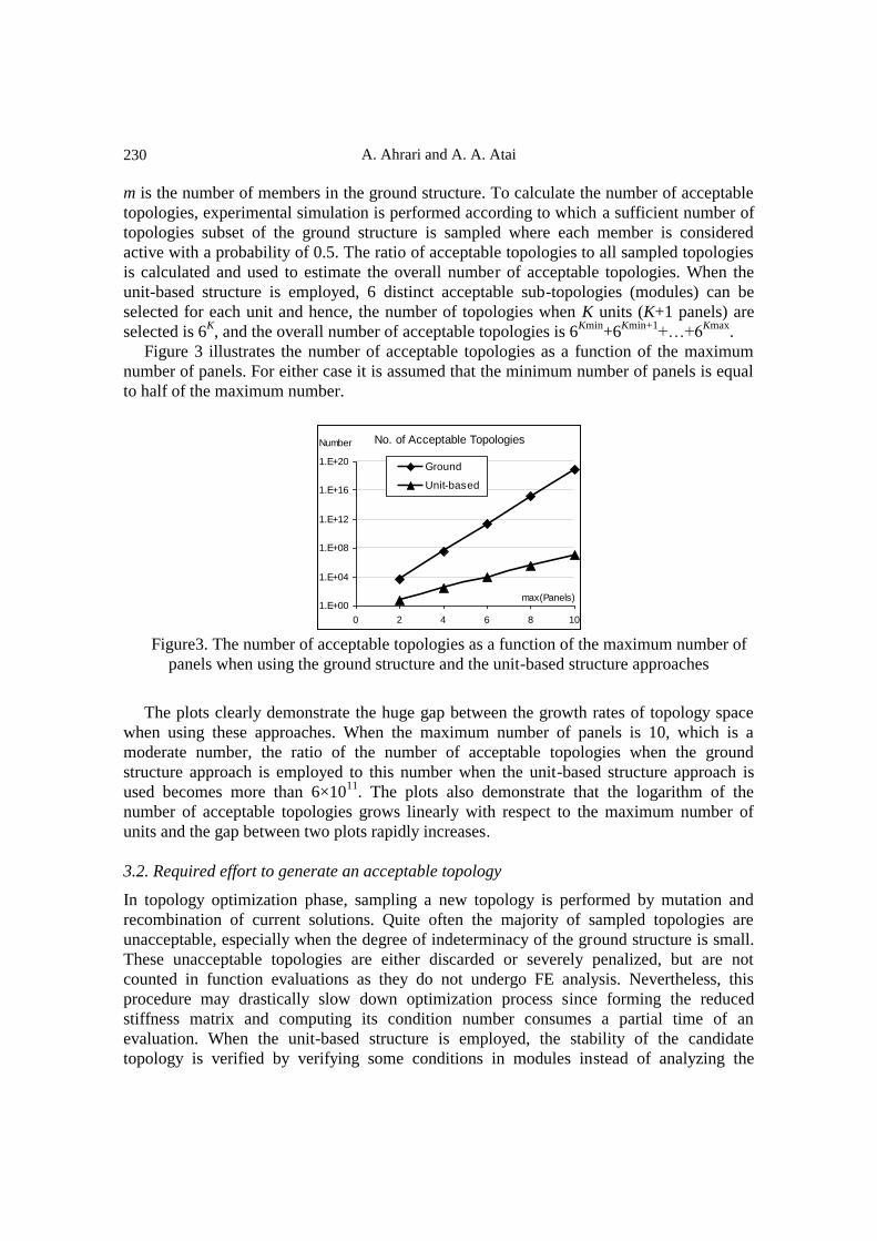
Figure 3 illustrates the number of acceptable topologies as a function of the maximum
number of panels. For either case it is assumed that the minimum number of panels is equal
to half of the maximum number.
No. of Acceptable Topologies
1.E+00
1.E+04
1.E+08
1.E+12
1.E+16
1.E+20
0 2 4 6 8 10
max(Panels)
Number
Ground
Unit-based
Figure3. The number of acceptable topologies as a function of the maximum number of
panels when using the ground structure and the unit-based structure approaches
The plots clearly demonstrate the huge gap between the growth rates of topology space
when using these approaches. When the maximum number of panels is 10, which is a
moderate number, the ratio of the number of acceptable topologies when the ground
structure approach is employed to this number when the unit-based structure approach is
used becomes more than 6×10¹¹
. The plots also demonstrate that the logarithm of the
number of acceptable topologies grows linearly with respect to the maximum number of
units and the gap between two plots rapidly increases.
3.2. Required effort to generate an acceptable topology
In topology optimization phase, sampling a new topology is performed by mutation and
recombination of current solutions. Quite often the majority of sampled topologies are
unacceptable, especially when the degree of indeterminacy of the ground structure is small.
These unacceptable topologies are either discarded or severely penalized, but are not
counted in function evaluations as they do not undergo FE analysis. Nevertheless, this
procedure may drastically slow down optimization process since forming the reduced
stiffness matrix and computing its condition number consumes a partial time of an
evaluation. When the unit-based structure is employed, the stability of the candidate
topology is verified by verifying some conditions in modules instead of analyzing the

EFFICIENT SIMULATION FOR OPTIMIZATION OF TOPOLOGY, SHAPE...
231
stiffness matrix. The advantages of this procedure are two-fold: first, the consumed time is
lessened as modules are formed independently and second, for simple base units, the
acceptability of a module relies on existence of sufficient members. For the bridge problem,
for instance, the candidate topology is acceptable if each module has at least 4 out of 5
members and hence, checking acceptability of the candidate topology requires neither
forming the stiffness matrix nor calculating its condition number. In the first iteration, all
probability mass function of all acceptable topologies should be similar. The method
employed here considers each member of a unit active with a probability of 0.5 and rejects
the unstable topologies.
Figure 4 illustrates the number of tried topologies and the consumed CPU time to
generate an acceptable topology as a function of the maximum number of panels. Again the
minimum number of panels was supposed to be equal to the half of the maximum number of
panels and sampling was performed uniformly over the acceptable feasible space. For the
ground structure approach, a sampled topology is first checked for having basic nodes and
existence of a minimum of active members. If confirmed, it undergoes calculating the
condition number of the stiffness matrix to check kinematic stability. For unstable
topologies, this number is theoretically infinitive, nonetheless, when it is numerically
calculated, a large value may be concluded due to unavoidable rounding errors.
Accordingly, large values of this number (for example larger than 1010
) refers to unstable
topologies. The condition number of the reduced stiffness matrix is also a good measure for
sensitivity of the solution to errors in input data which is of great importance when robust
optimization is desired.
1
10
100
1000
10000
3 6 9 12 15
max(Panels)
Number
1
10
100
1000
10000
Time
(ms)Ground:TrialsUnit:TrialsGround:TimeUnit:Time
0
20
40
60
80
100
3 6 9 12 15
max(Panels)
Number
0
5
10
15
20
25
Time
(ms)
Ground:TrialsUnit:TrialsGround:TimeUnit:Time
(a) (b)
Figure4. Required CPU Time (ms) and the number of tried topologies to generate an
acceptable topology as a function of maximum number of units when the concepts of the
ground structure (GS) and the Unit-based structure (UBS) are employed: a) logarithmic
scale; b) linear scale.
The test was run on a 4-core processor (4×2.66 GHz) PC with 2G RAM. The plots
demonstrate that both the number of tried topologies and the required computation time
grow exponentially when the ground structure approach is employed while they grow

A. Ahrari and A. A. Atai
232
linearly when the unit-based structure is employed. When the maximum number of panels is
selected as 14, the required time to generate an acceptable topology becomes more than 1
second, which implies that application of the ground structure approach is impractical. If the
unit-base structure is employed, the corresponding time is only 7 ms.
3.3. Size of topology space
As relative coordinates is employed, the range of shape variables can be set to (0,u0] while
the requirement for nodal adjacency is always fulfilled and adjacent nodes may approach as
close as desired. Apart from that, knowing that variation in height of the bridge would be
gradual, use of relative coordinates even for vertical poison of the upper nodes could be
beneficial. To check this experimentally, the bridge example is optimized for shape and size
while its topology is similar to what was presented in Figure 1a.
Table 1. Data for simulation of the bridge truss problem
Design Variables
Shape (19) x3, y3, x5, y5, x7, y7, x9, y9, x11, y11, x13, y13, x15, y15, x17, y17, x19, y19, y21
Size (48) ai , i=1,2,…,48
Constraints Stress (σc)i ≤ 36 (248.2 MPa) ksi ; (σt)i ≤ 36 ksi (248.2 MPa), i=1,2,…,48
Displacement ui ≤ 10 in (25.4 cm)
Buckling |(σc)i| ≤ αEai/li2 , i=1,2,…,48 , α=4
Search Range
Shape
Variables
Absolute
150(i-1)-200 ≤ xi in ≤ 150(i-1)+200 , i=3,5,…,19
381 (i-1)-508 ≤ xi cm ≤ 381 (i-1)-508 , i=3,5,…,19
50 in (127 cm) ≤ y3 ≤ 1000 (2540 cm)
50 in (127 cm) ≤ yi ≤ 1500 in (3810 cm) , i=3,5,…,21
Relative
100 ≤ xi ≤ 900 , i=3,5,…,19
50 in (127 cm) ≤ y3 ≤ 1000 in (2540 cm) ;
-100 in (-254 cm) ≤ yi ≤ 300 in (762 cm) , i=5,7,…,21
Size Variables 1 in2 (6.45 cm
2) ≤ Ai ≤100 in
2 (645.15 cm
2)
Loading W=-200 lb/in (-35025 N/m)
Mechanical Properties
Modulus of elasticity: E=29000 ksi (200 GPa)
Density of the material: ρ=0.3 lb/in3 (0.0814 N/cm
3)
Shape optimization includes determining vertical and horizontal position of upper nodes
by a simple ES-based optimizer explained in appendix. The following options for
representation of nodal coordinates are employed independently:
I) Absolute coordinates for both vertical and horizontal position of the nodes.
EFFICIENT SIMULATION FOR OPTIMIZATION OF TOPOLOGY, SHAPE...
233
II) Absolute coordinates for vertical but relative coordinates for horizontal position of
the nodes.
III) Relative coordinates for both vertical and horizontal position of the nodes.
If relative coordinates are used, the design variable specifies vertical/horizontal distance
from the node on the left side in the same cord. Data required for simulation is presented in
Table 1. For each case 50 independent runs were executed while population size and
maximum number of iterations were set to 200 and 1000 respectively. Having analyzed
output data, Expected Running Time (ERT) to reach a target structural weight was
computed according to the following relation [35]:
ERT=FES/SR
(1)
where SR denotes the fraction of runs that could reach the desired target weight and FES is
the average number of evaluations of successful runs to reach that weight. The calculated
values of ERT as a function of the target weight are plotted in Figure 5a. Figure 5b depicts
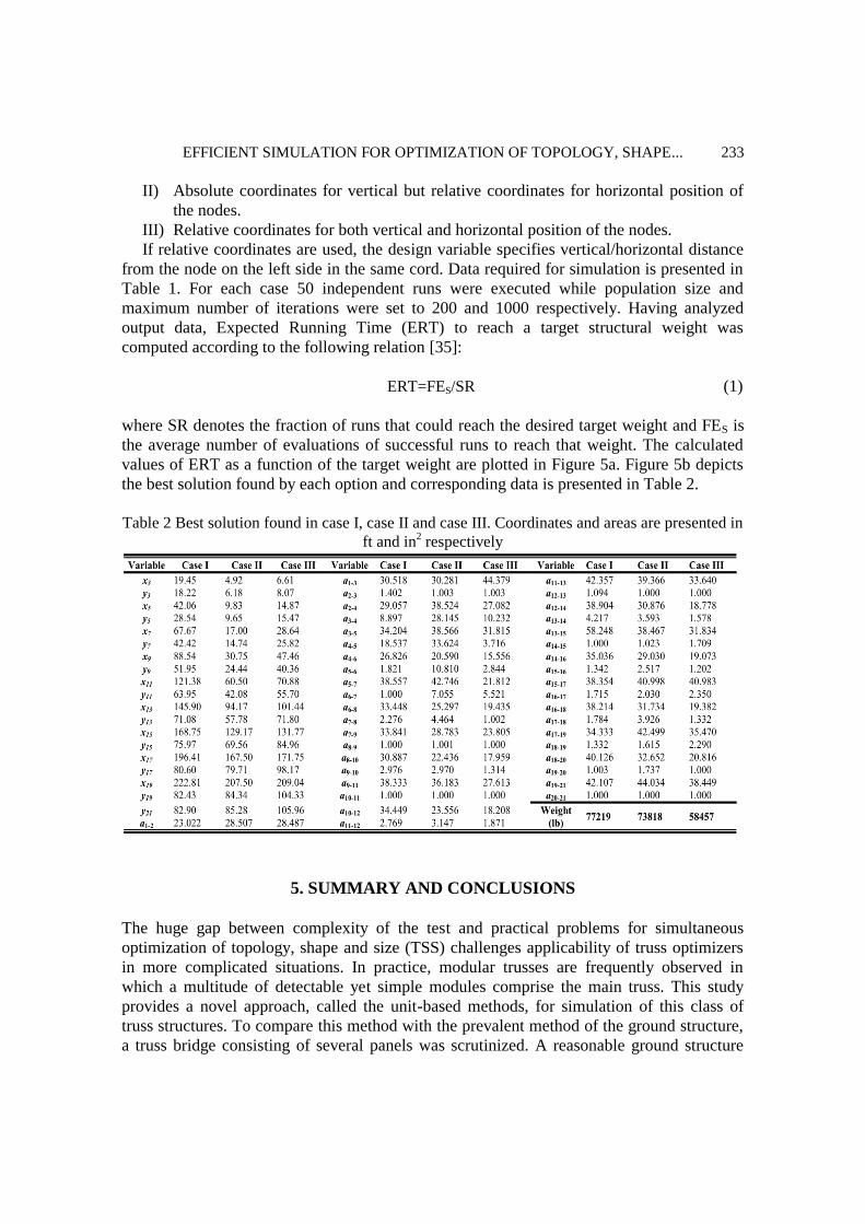
the best solution found by each option and corresponding data is presented in Table 2.
Table 2 Best solution found in case I, case II and case III. Coordinates and areas are presented in
ft and in2 respectively
5. SUMMARY AND CONCLUSIONS
The huge gap between complexity of the test and practical problems for simultaneous
optimization of topology, shape and size (TSS) challenges applicability of truss optimizers
in more complicated situations. In practice, modular trusses are frequently observed in
which a multitude of detectable yet simple modules comprise the main truss. This study
provides a novel approach, called the unit-based methods, for simulation of this class of
truss structures. To compare this method with the prevalent method of the ground structure,
a truss bridge consisting of several panels was scrutinized. A reasonable ground structure

A. Ahrari and A. A. Atai
234
which allowed for generating candidate solutions with different number of panels was
configured. It was demonstrated that the required computation effort, measured in the forms
of the number of unacceptable sampled candidates and CPU time to generate an acceptable
topology, when the ground structure option is employed, grows exponentially with respect
to the number of panels which restrict applicability of this option even for moderate number
of panels. On the contrary, these quantities grow linearly when the unit-based method is
employed and besides, the size of topology space grows at much lower rate in comparison
with the ground structure approach. Apart from that, use of relative coordinates was strongly
advocated by empirical results from a simple ES-based optimizer. Comparison among plots
of ERT and quality of the final solution confirmed benefits of relative coordinates for both
horizontal and vertical nodal positions.
The unit-based method can be employed by meta-heuristics to handle the problem
complexity of TSS optimization for larger structures. This, in fact, can reduce the gap
between the intricacy of truss structures in practice and those employed as benchmarks in
literature. More complex test functions, within fixed computation resources, can compare
applicability and practicality of truss optimizers more reliability, which is a step forward to
extend application of stochastic optimization algorithms in engineering.
REFERENCES
1. Lamberti L, Pappalettere C. Metaheuristic design optimization of skeletal structures: a
review, Comput Technol Reviews, 2011; 4: 1–32.
2. Topping BHV. Shape optimization of skeletal structures: a review, J Struct Eng, ASCE
1983; 109(8): 1933–51.
3. Deb K, Gulati S. Design of truss-structures for minimum weight using genetic
algorithms, Finite Elem Anal Des 2001; 37(5): 447–65.
4. Degertekin SO. Improved harmony search algorithms for sizing optimization of truss
structures, Comput Struct 2012; 92-93: 229–41.
5. Sonmez M. Artificial Bee Colony algorithm for optimization of truss structures, Appl
Soft Comput, 2011; 11(2): 2406–2418.
6. Kaveh A, Talatahari S. Size optimization of space trusses using Big Bang–Big Crunch
algorithm, Comput Struct 2009; 87(17): 1129–40.
7. Kaveh A. Talatahari S. Optimization of large-scale truss structures using modified
charge system search, Int J Optim Civil Struct Eng 2011; 1: 15–28.
8. Kaveh A, Talatahari S. Optimal design of skeletal structures via the charged system
search algorithm, Struct Multidiscip Optim 2010; 41(6): 893–911.
9. Talatahari S, Kaveh A, Sheikholeslami R. Chaotic imperialist competitive algorithm for
optimum design of truss structures, Struct Multidiscip Optim 2012; 46(3): 355–67.
10. Li LJ, Huang ZB, Liu F, Wu QH. A heuristic particle swarm optimizer for optimization
of pin connected structures, Comput Struct 2007; 85(7): 340–49.
11. Rahami H, Kaveh A, Aslani M, Najian-Asl R. A hybrid modified Genetic-Nelder Mead
Simplex algorithm for large-scale truss optimization, Int J Optim Civil Struct Eng 2011;
1: 29–46.

EFFICIENT SIMULATION FOR OPTIMIZATION OF TOPOLOGY, SHAPE...
235
12. Kaveh, A. and S. Talatahari, Particle swarm optimizer, ant colony strategy and
harmony search scheme hybridized for optimization of truss structures, Comput Struct
2009; 87(5): 267–83.
13. Hadidi A, Kaveh A, Farahmand-Azar B, Talatahari S, Farahmandpour C. An efficient
hybrid algorithm based on particle swarm and simulated annealing for optimal design
of space trusses, Int J Optim Civil Struct Eng 2011; 1(3): 377–95.
14. Kaveh A, Zolghadr A. Truss optimization with natural frequency constraints using a
hybridized CSS-BBBC algorithm with trap recognition capability, Comput Struct 2012;
102–103: 14–27.
15. Hasançebi O, Çarbaş S, Doğan E, Erdal F, Saka MP. Performance evaluation of
metaheuristic search techniques in the optimum design of real size pin jointed
structures. Comput Struct 2009; 87(5): 284–302.
16. Lee KS, Han SW, Geem ZW. Discrete size and discrete-continuous configuration
optimization methods for truss structures using the harmony search algorithm. Int J
Optim Civil Struct Eng 2011; 1: 107–26.
17. Šilih S, Kravanja S, Premrov M. Shape and discrete sizing optimization of timber
trusses by considering of joint flexibility, Adv Eng Software 2010; 41(2): 286–94.
18. Lamberti L, An efficient simulated annealing algorithm for design optimization of truss
structures. Comput Struct 2008; 86(19): 1936–53.
19. Gholizadeh S, Barzegar A, Gheyratmand C. Shape optimization of structures by
modified harmony search. Int J Optim Civil Struct Eng 2011; 1(3): 485–94.
20. Gholizadeh S, Barati H. A comparative study of three metaheuristics for optimum
design of trusses. Int J Optim Civil Struct Eng 2012; 3: 423–41.
21. Ruiyi S, Liangjin G, Zijie F. Truss Topology Optimization Using Genetic Algorithm
with Individual Identification. Proceedings of the World Congress on Engineering,
London, UK, 2009.
22. Su R, Wang X, Gui L and Fan Z. Multi-objective topology and sizing optimization of
truss structures based on adaptive multi-island search strategy. Struct Multidiscip Optim
2011; 43(2): 275–86.
23. Luh GC. Lin CY. Optimal design of truss structures using ant algorithm. Struct
Multidiscip Optim 2008; 36(4): 365–79.
24. Rajan SD. Sizing, shape, and topology design optimization of trusses using genetic
algorithm, J Struct Eng 1995; 121(10): 1480–7.
25. Rahami H, Kaveh A, Gholipour Y. Sizing, geometry and topology optimization of
trusses via force method and genetic algorithm. Eng Struct 2008; 30(9): 2360–9.
26. Luh GC, Lin CY. Optimal design of truss-structures using particle swarm optimization,
Comput Struct 2011; 89(23): 2221–32.
27. Hasançebi O, Erbatur F. Layout optimisation of trusses using simulated annealing. Adv
Eng Software 2002; 33(7): 681–96.
28. Wu CY, Tseng KY. Truss structure optimization using adaptive multi-population
differential evolution, Struct Multidisc Optim 2010; 42(4): 575–90.
29. Alimoradi A, Foley CM, Pezeshk S. Benchmark Problems in Structural Design and
Performance Optimization: Past, Present, and Future-Part I, In 19th Analysis and
Computation Specialty Conference, 2010.

A. Ahrari and A. A. Atai
236
30. Hasançebi O. Adaptive evolution strategies in structural optimization: Enhancing their
computational performance with applications to large-scale structures. Comput Struct
2008; 86(1): 119–32.
31. Zawidzki M, Nishinari K. Modular Truss-Z system for self-supporting skeletal free-
form pedestrian networks. Adv Eng Software 2012; 47(1): 147–59.
32. Noilublao N, Bureerat S. Simultaneous topology, shape and sizing optimisation of a
three-dimensional slender truss tower using multiobjective evolutionary algorithms.
Comput Struct 2011; 89(23–24): 2531–38.
33. Kaveh A, Talatahari S. Optimization of large-scale truss structures using modified
charged system search, Int J Optim Civ Struct Eng 2011; 1: 15–28.
34. Kaveh A, Fazli H. Free vibration analysis of locally modified regular structures using
shifted inverse iteration method. Comput Struct 2012; 108–109: 75–82.
35. Auger A, Hansen N. A restart CMA evolution strategy with increasing population size.
Proceedings of the 2005 IEEE Congress on Evolutionary Computation, 2005, pp.
1769–76.
36. Beyer H-G. Schwefel H-P. Evolution strategies–A comprehensive introduction, Nat
Comput 2002. 1(1): 3–52.
37. Hansen N, Ostermeier N. Completely derandomized self-adaptation in evolution
strategies. Evol Comput 2001; 9(2): 159–95.
APPENDIX: ES-BASED OPTIMIZER (SHAPE AND SIZE)
The employed truss optimizer is based on a standard (μ/μW, λ)-ES for continuous
optimization. For detailed information on contemporary Evolution Strategies for continuous
parameter optimization the readers are referred to [36]. The following algorithmic options
were used:
- μ=[λ/2]
- An independent step size for each design (object variable) which is self-adapted.
- Simultaneous Mutation of all variables by Interrupted Normal distribution.
- Global weighted recombination for both design (object) and strategy variables.
Infeasible individuals are penalized as follows:
dbs
PPPWf 1
where
n
all
jiall
idi
N
i
did
m
i
all
biall
bibi
N
i
bib
m
all
jiall
yisi
N
i
sis
Nielseif
ifddppP
Nielseif
ifppP
Nielseif
ifppP
n
m
m
...1,1
/,1
...1,0&
1
/,1
...1,1
/,1
1
2
1
2
1
2
The following is the pseudo code of a standard ES for unconstrained continuous

EFFICIENT SIMULATION FOR OPTIMIZATION OF TOPOLOGY, SHAPE...
237
optimization. For each design variable, an independent step size is allotted which is self-
adapted:
1: Specify λ and search ranges of design variables (L,U)
2: Let μ=[λ/2], τ0=2(NVAR)(-0.5)
, τ=2(NVAR)
(-0.25), where NVAR refers to the number of design
variables which is equal to overall number of shape and size variables.
4: Sample the initial design, XR, randomly within the range. Let the initial step size vector,
σR, be one-fourth of the corresponding search range
5: While not a convergence criterion is satisfied
6: Repeat until λ candidate solutions are generated:
7: Generate σj by mutation of σR according to the following relation:
)1,0(exp,...,)1,0(exp,)1,0(exp)1,0(exp0
NNNNRj
where denotes element-wise multiplication and N(0,1) refers to a random
number sampled from Standard Normal distribution.
8: Generate Xj by using σj as the vector of step sizes from interrupted Normal
Distribution. If Xj Fulfills node adjacency requirement, accept it, otherwise try
sampling a new candidate solution.
9: Calculate fj, the objective function value at Xj.
11: End Repeat
12: Sort individuals according to their fitness. Update σR and XR according to the
following relations:
11
logexp;k
kkRkk
kRwXwX
;
where wk is the weight of the kth
parent (after sorting). Similar to the CMA-ES
code, a logarithmic scale is used for the weights [37]:
),ln()1ln(,/1
kwk
jjkk
13: End while