efficient path determining robot jamie greenberg jason torre
Post on 20-Dec-2015
217 views
TRANSCRIPT
Efficient Path Efficient Path Determining Determining
RobotRobotJamie GreenbergJamie Greenberg
Jason TorreJason Torre
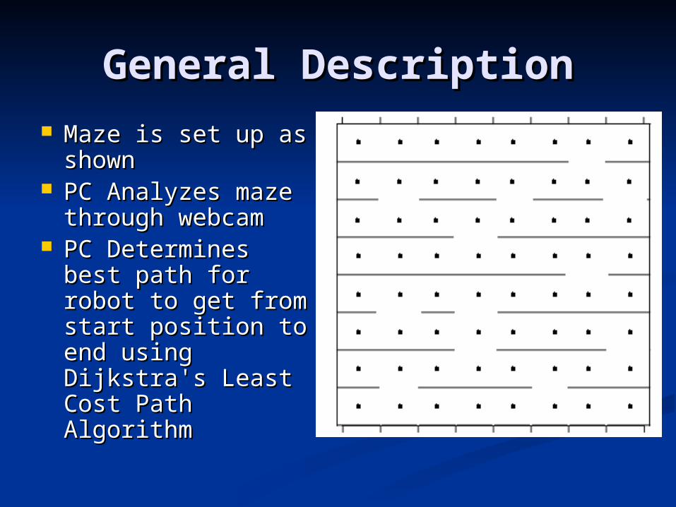
General DescriptionGeneral Description Maze is set up as Maze is set up as
shownshown PC Analyzes maze PC Analyzes maze
through webcamthrough webcam PC Determines PC Determines
best path for robot best path for robot to get from start to get from start position to end position to end using Dijkstra's using Dijkstra's Least Cost Path Least Cost Path AlgorithmAlgorithm

General Description General Description (continued)(continued)
PC translates path PC translates path into a set of into a set of commands and commands and sends them to the sends them to the HCS12 through HCS12 through the serial portthe serial port
Robot follows Robot follows commands to commands to travel the best travel the best path to the finishpath to the finish

Image ProcessingImage Processing Laptec Webcam connected to PC through Laptec Webcam connected to PC through
USB portUSB port Image is captured through Java Media Image is captured through Java Media
FrameworkFramework Pixel information is pulled from the image Pixel information is pulled from the image
using Java PixelGrabber classusing Java PixelGrabber class Pixel data for areas of interest is analyzed to Pixel data for areas of interest is analyzed to
determine if color best represents a wall determine if color best represents a wall (white) or a blank space (black)(white) or a blank space (black)
Use this data to determine what grid Use this data to determine what grid positions have a blank space (no wall) and positions have a blank space (no wall) and designate them as “nodes”designate them as “nodes”

Dijkstra’s AlgorithmDijkstra’s Algorithm Start with a “cost” of zero for the start node Start with a “cost” of zero for the start node
and infinity at every other node. and infinity at every other node. Iterate through every node and determine Iterate through every node and determine
it’s distance from the start node (if directly it’s distance from the start node (if directly connected)connected)
Mark the node with the least cost and Mark the node with the least cost and determine the costs of all unmarked nodes determine the costs of all unmarked nodes to this nodeto this node
Repeat for every node until least cost node Repeat for every node until least cost node is the finishing node.is the finishing node.
Once this is determined, the shortest path Once this is determined, the shortest path is the reverse order of the nodes previously is the reverse order of the nodes previously markedmarked

Getting the data to the Getting the data to the robotrobot
Once the best path is found, the path is Once the best path is found, the path is converted on the PC to a set of binary converted on the PC to a set of binary commandscommands
This data is sent to the Motorola 68HCS12 This data is sent to the Motorola 68HCS12 through the serial port on the PC and the SCI through the serial port on the PC and the SCI port on the HCS12. port on the HCS12.
When a “FINISHED” command has been When a “FINISHED” command has been received by the robot a command will be sent received by the robot a command will be sent back to the PC that will notify the user to back to the PC that will notify the user to remove the serial cable and press the Go remove the serial cable and press the Go button on the robot. When GO is pressed, the button on the robot. When GO is pressed, the robot should begin it’s path towards the finish. robot should begin it’s path towards the finish.

CommandsCommands The following commands will be used to guide the The following commands will be used to guide the
robot through the maze:robot through the maze:
CommanCommandsds
Bit SetupBit Setup DescriptionDescription
LEFTLEFT 001 xxxxx 001 xxxxx Move the robot left xxxxx grid Move the robot left xxxxx grid coordinates. This location will never coordinates. This location will never be larger than 7, as the grid has only 8 be larger than 7, as the grid has only 8 coordinates. coordinates.
RIGHTRIGHT 010 xxxxx 010 xxxxx Move the robot right xxxxx grid Move the robot right xxxxx grid coordinates. This location will never coordinates. This location will never be larger than 7, as the grid has only 8 be larger than 7, as the grid has only 8 coordinates. coordinates.
FORWARDFORWARD 011 011 00000 00000
Move the robot forward 1 row.Move the robot forward 1 row.
FINISHEDFINISHED 100 100 0000000000
Notify robot that it has reached it’s Notify robot that it has reached it’s destination and adjust status LEDs. destination and adjust status LEDs.

Communications TestCommunications Test
At the beginning of the program At the beginning of the program (before web capture), the serial (before web capture), the serial connection will be testedconnection will be tested
A binary “test” sequence will be sent A binary “test” sequence will be sent to the robot and it will be echoed to the robot and it will be echoed back to the PC.back to the PC.
If the echo is not received in 5 If the echo is not received in 5 seconds an error message will be seconds an error message will be displayeddisplayed
PC User InterfacePC User Interface
The PC will be used to guide the user The PC will be used to guide the user through the processthrough the process Instruct the user to attach the serial cable and Instruct the user to attach the serial cable and
reset the robotreset the robot Notify user if communications test was Notify user if communications test was
successfulsuccessful Notify user that image analysis is in progressNotify user that image analysis is in progress Notify user if path does not existNotify user if path does not exist Notify user that commands are being sent to Notify user that commands are being sent to
the HCS12the HCS12 Ask user to remove serial connection and Ask user to remove serial connection and
press the GO buttonpress the GO button

Robot Design Robot Design
Tamiya Robot kitTamiya Robot kit The DC motor is FA-The DC motor is FA-
130 by Tamiya 130 by Tamiya The whole kit The whole kit
measured 6.5” X measured 6.5” X 4.25” X 3.75” height, 4.25” X 3.75” height, available surface available surface area after the area after the bottom deck is bottom deck is covered is 4.5” X covered is 4.5” X 2.5” 2.5”
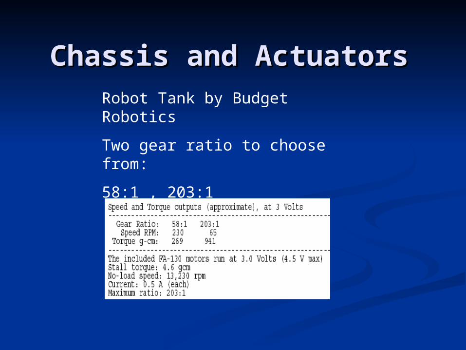
Chassis and ActuatorsChassis and ActuatorsRobot Tank by Budget Robotics
Two gear ratio to choose from:
58:1 , 203:1

Hardware UtilizedHardware Utilized
Proximity SensorsProximity Sensors Opto-reflectorsOpto-reflectors Chasis and DC motorsChasis and DC motors H bridgesH bridges BatteriesBatteries

Proximity sensorsProximity sensorsSharp GP2D15 IR Proximity Sensor
Range between 0 cm and 80 cm
Beam width of 45-50°
This model can be adjusted to yield a digital output when the robot comes to close to the wall (~ 2 cm)
No external circuitry is needed

Opto-reflectorOpto-reflectorOptek OPB745 opto reflector
Responsible for informing that the vehicle has arrived reached a mrker
The sensor will yield a digital input value when the robot crosses a piece of reflective tape, and modifications are done on the signal handling circuit that was completed previously (IDE).

Battery and powerBattery and power
4 AA sized battery for the vehicle 4 AA sized battery for the vehicle (in the kit)(in the kit)
Additional D Cell battery cells Additional D Cell battery cells used to drive all the sensors and used to drive all the sensors and HCS12 boardHCS12 board

Block DiagramBlock Diagram
DC Motor
H bridges
DC Motor
HCS12
PW
M 0
-2
Opto-reflectors
Proxy Sensors
PT 0-5

Top Level
HCS12
Hole for wires
User Interface
Sensor Circuitry
Proxy sensor
Proxy sensor
Bottom Level
Opto-reflector and circuitry
Batteries
H Bridges, DC Motors and voltage regulator
Overhead view Overhead view

User interfaceUser interface
Error
Moving
Finished
On/OffGO Download Complete complete
DifficultiesDifficulties
The camera must be nearly perfectly The camera must be nearly perfectly calibrated so that the rectangular calibrated so that the rectangular arrays of pixels sampled are always the arrays of pixels sampled are always the correct ones correct ones
Calibrating the opto reflector correctly Calibrating the opto reflector correctly because it has been known to be because it has been known to be unreliableunreliable
Calibrating the proxy sensors so as not Calibrating the proxy sensors so as not to give too large a rangeto give too large a range

Webcam Alignment Webcam Alignment UtilityUtility
A small utility will be created to A small utility will be created to assist in positioning of the webcamassist in positioning of the webcam
The utility will display a snapshot of The utility will display a snapshot of the grid with boxes around the areas the grid with boxes around the areas that should contain the edges of that should contain the edges of each grid position (either a wall or each grid position (either a wall or an opening)an opening)
If the camera needs to be moved, the If the camera needs to be moved, the user can retry the calibration until it user can retry the calibration until it is satisfactorily lined upis satisfactorily lined up

CostCost
Item Cost
Labtec Webcam $19.80 from staples
Java API Free from java.sun.com
Motorolla 68HCS12 Microcontroller $180.00 from CE department
Remote Control Tank $35.95 from budgetrobotics.com
LM298 H bridges (2) $10.90 from digikey.com
Optek OPB745 Opto-Isolators(2) $12.00 from CE department
Various other power circuitry and batteries $30.00
Maze for Robot $20.00 Approx

Questions?Questions?