efficient kinematic solution to a multi-robot with serial ... filetion to a multi-robot system with...
TRANSCRIPT

Efficient Kinematic Solution to a Multi-robotwith Serial and Parallel Mechanisms
Houxiang Zhang, Gionata Salvietti, Wei Wang, Guoyuan Li, Junzhi Yu, and Jianwei Zhang
Abstract— This paper presents an efficient kinematical solu-tion to a multi-robot system with serial and parallel mecha-nisms. JL-I is a reconfigurable robot featuring active sphericaljoints formed by serial and parallel mechanisms endowing therobotic system with the ability of changing shapes in threedimensions. The active joint here can combine the advantagesof the high rigidity of a parallel mechanism and the extendedworkspace of a serial mechanism. However, the kinematicanalysis of the serial and parallel mechanism is always thebottleneck in designing a robot and control realization. Inorderto deal with this problem, the whole kinematical analysis isorganized in the sequence from the direct mechanical analysisrelated to the serial and parallel mechanism over the numericalsolutions to the simplified kinematics expression. The latestresults obtained demonstrate that the deduced closure-formsolution is time efficient and easy to implement while offeringa satisfactory motion performance in on-site experiments.
I. I NTRODUCTION
Mobile robots have the ability to move around in theirenvironment and are not fixed to one physical location.Currently, mobile robots are the focus of a great deal ofresearch and almost every major university has one ormore labs that focus on mobile robotic topics. The modularapproach makes the mobile robotic system versatile, robust,cost-effective and fast to prototype. The robots can adoptdifferent configurations to match various tasks and suitcomplex environments [1], [2].
This paper presents the reconfigurable mobile robot JL-I which currently comprises three identical modules (seeFig. 1). Actually, it is a general mobile platform and can beextended for various applications [3], [4]. Each single roboticunit in the JL-I system has reasonable locomotion ability.With the docking mechanisms, the units can connect to forma train-configuration which possesses a higher adaptabilityto rugged terrains. After docking, an equivalent sphericaljoints is relized via serial and parallel mechanism to enablethe adjacent modules to adopt configurations by pitching,yawing, and rotating movements. However, the kinematicanalysis of the serial and parallel mechanism is always
H. Zhang is with the Department of Informatics,University of Hamburg, Germany (Corresponding e-mail:[email protected]).
G. Salvietti is a Ph.D candidate with the Department of InformationEngineering, University of Siena, Italy.
W. Wang is with the Robotics Institute, Beijing University of Aeronauticsand Astronautics, Beijing, China.
G. Li is a Ph.D candidate at TAMS, with the Department of Informatics,University of Hamburg, Germany.
J. Yu is with the Institute of Automation, Chinese Academy ofSciences,Beijing, China.
J. Zhang is with the Department of Informatics, University of Hamburg,Germany.
the bottleneck in designing a robot and its control real-ization. This paper emphasizes the locomotion capabilitiesand reconfiguration realization. The remainder of the paperis organized as follows. In Section II, a brief overviewof the application of the parallel and serial mechanism ispresented. Section III is devoted to an efficient locomotionsupported by a comprehensive workspace and kinematicsanalysis. Obtained experimental results are further illustratedin Section IV. Finally, Section V concludes the paper withan outline of future work.
II. A PPLICATIONS OFSERIAL AND PARALLEL
MECHANISMS IN ROBOTICS
The serial mechanism has been adopted by mobile robotsdue to the extended workspace of the mechanism. Sincethe mechanical structure is always simple and direct, themovement control is easy to realize. In some cases, we callthe traditional serial mechanism an open-loop mechanism.However, the advantages are offset by the low rigidity andthe limited capability of payload. In order to realize a strongand powerful actuating joint only with serial mechanism, thewhole mechanical design will be rather big and heavy.
With the development of mechanical technology, a parallelmechanism (PM) provides an alternative solution for mobilerobots due to the higher positioning accuracy, higher controlrigidity, and good dynamic behavior [5]. Note that the paral-lel mechanism is used firstly to realize robotic manipulators[6]. A generalized parallel manipulator is a closed-loop kine-
Z
X
YO
Fig. 1. The concept design of JL-I robot.
The 2010 IEEE/RSJ International Conference on Intelligent Robots and Systems October 18-22, 2010, Taipei, Taiwan
978-1-4244-6676-4/10/$25.00 ©2010 IEEE 6101

matic chain mechanism whose end-effector is linked to thebase by several independent kinematic chains. In many cases,the parallel mechanism owns several legs or limbs, each ofthem comprises of different kinds of joints in series, suchas universal and prismatic joints. The Stewart mechanismas a well-known parallel design owns six limbs and sixdegrees of freedom [7]. As a result, it needs six actuators intotal. The Stewart mechanism has been proposed for differentrobotic applications. Recently, many researchers have paida lot of attention on researching the translational parallelmanipulators and mechanisms due to only three degrees offreedom and outputs translational motion without changingits orientation [8]. Meanwhile, many alternative mechanicalstructures with less number of limbs have been proposedworldwide to overcome the shortcomings associated with six-limb platforms, such as tripod [10].
There have been many research achievements in the designof manipulators [11] [12]. However, parallel mechanisms canonly work in a very limited workspace even it is rathersophisticated. It is inevitable that the hybrid manipulator willbe the possible idea that could integrate the advantages ofboth the parallel mechanism and serial mechanism. Someinteresting prototypes are presented with the time. A hybrid(parallel serial) manipulator consisting of two serially con-nected parallel mechanisms is presented in [13], which givesits closed-form solution for the direct and inverse positionproblems. The other hybrid manipulator in [14] is with abase and two platforms in series.
Recently, there has been an increasing interest usingparallel mechanism for designing mobile robots [15]. Areconfigurable parallel mobile robot which can be configuredto 4R and 5R closed kinematical chains is proposed in [16].The robot can form three-dimensional structures and reacha certain height. However these advantages are gained atthe expense of a reduced workspace, difficult mechanicaldesign and more complex kinematics and control algorithms[17]. As a result, researchers are beginning to combine theclassical serial structure with parallel mechanism approachfor the mobile robots’ design too. The hybrid approach canovercome the limited workspace of the parallel mechanismand can provide features of both the serial and parallelmechanism. Currently, a lot of similar research can be foundworldwide.
The JL-I robot presented in this paper owns three uniformunits. One module is about 43 cm long, 25 cm wide and15 cm high, and constitutes an entire robot system that canperform distributed activities [18]. The mechanical structureof the module comprises two powered tracks, a serial mech-anism, a parallel mechanism and a docking mechanism. JL-I features serial and parallel mechanisms to form a 3-DOFactive spherical joint. By controlling the active joints and thedocking mechanisms, the robot can change its shape in threedimensions. The serial mechanism can rotate 360∘ around theZ axis. The parallel mechanism can pitch around theY axisand yaw according to theX axis.
Although some related work focusing on mechanical de-sign, and control realization [19] on the JL robotic system
has been presented previously, many important issues relatedto serial and parallel mechanism kinematics and inverse kine-matics which particularly distinguishes the JL system fromother similar robotic platforms have not been thoroughlyinvestigated as yet. The following sections will elaborateonthese issues.
III. A NALYTICAL SOLUTION TO EFFICIENT
LOCOMOTION
A. The DOF of the Active Joint
It is noted that the calculations involved in performinga desired manipulation (forward kinematics) with a parallelmechanism are usually harder and have more than one uniquesolution. To achieve this reconfiguring capability, some re-lated issues on the kinematics analysis of two connectedmodules will be briefly reviewed. Fig. 2 demonstrates thekinematics model of the joint between two modules. Therequired orientation for the reference frameO′X ′Y ′Z ′ on theback module is implemented by a rotation of�z, a pitchingangle�y and a yawing angle�x according to the relative axes.Actually the pitching and yawing motions are implementedby the outstretching and returning movement of theL1, L2
of the parallel mechanism, and the rotation of�z is actuatedby the serial mechanism. The freedom of the reconfiguringmovement is three and can be represented by a generalizedcoordinate�, (1). The joint variants of the movement aredefined asq, (2).
� = [�x, �y, �z]T (1)
q = [L1, L2, �z]T (2)
As can be observed from Fig. 2, after docking, the JLsystem has eight joints as a whole. Three Hooker joints areat pointsO, A, and B; two linear movement joints are atlinks AC andBD; one rotating joint is along the axisZ1Z2
and two spherical joints are atC and D. According to themechanical principle, the DOF can be calculated as follows:
m = 6(n− g − 1) +
g∑
i=1
fi = 3 (3)
wherem stands for the DOF;n denotes the movable linksof the active joint;g indicates the total number of the joints;and fi is the DOF of the relative joints. The details of theDOF analysis can be found in [20].
As mentioned above, the angle�z is required to havea 360∘ rotation around theZ axis. Note that�z is anindependent DOF actuated by the serial mechanism andit normally occurs after the pitching movement or yawingmovement in practice. So we only need to focus on theworkspace of�x and �y since both pitching and yawingmovements are dependent on the extending or contactingcooperation ofL1 andL2 in the parallel mechanism.
In practice, the maximum positions should be calculatedconsidering the mechanical constraints and collision avoid-ance. The pitching and yawing workspaces are obtained,
6102

'
A
B
C
D
PQ
L1
L2
2K
F
E
X'
Y '
Z '
X
Y
Z
M M'
Z2Z1
P1
P2
R1
O O
Fig. 2. The kinematics mode of the active spherical joint.
details can be found in [20]. The restricted workspace foravoiding collision is shown in (4).
{
�x ∈ [−32.0∘,−8.0∘] ∪ [+8.0∘,+32.0∘]�y ∈ [−50.0∘,−24.0∘] ∪ [+24.0∘,+50.0∘]
(4)
To further simplify the mechanical structure, we can de-sign the workspace of�x, �y to be the same, e.g., both within−50− 50∘, which not only reduces the implementation costbut also slightly increases redundancy for practical operation.
B. Direct and Inverse Kinematics Analysis
The relationship betweenq and � was deduced in ourprevious paper [1] and is shown in (5) and (6), which willbe useful for calculating the value ofq from the knowngeneralized coordinate� in motion control.
L12 = [K(cos �y cos �z + sin �x sin �y sin �z)
−K(− sin �z cos �y + sin �x sin �y cos �z)+ L cos �x sin �y −K cos �z −K sin �z]
2
+ [K(cos �x sin �z)−K(cos �x cos �z)− L sin �x −K sin �z +K cos �z]
2
+ [K(− sin �y cos �z + sin �x cos �y sin �z)−K(sin �y sin �z + sin �x cos �y cos �z)+ L cos �x cos �y]
2
(5)
L22 = [K(cos �y cos �z + sin �x sin �y sin �z)
+K(− sin �z cos �y + sin �x sin �y cos �z)+ L cos �x sin �y −K cos �z +K sin �z]
2
+ [K(cos �x sin �z) +K(cos �x cos �z)− L sin �x −K sin �z −K cos �z]
2
+ [K(− sin �y cos �z + sin �x cos �y sin �z)+K(sin �y sin �z + sin �x cos �y cos �z)+ L cos �x cos �y]
2
(6)
However, the direct relationship or kinematics is stillunclear. Normally a direct kinematics solution is hard to findbecause of multiple possible solutions due to the character-istics of extension movements of the parallel mechanism.A numerical method instead is used to resolve the problemso that the required workspaces of joint movements can beplotted in green as shown in Fig. 3.
The practical workspace ofL1 andL2 should be within thesurfaces markedE1F1G1H1 andE2F2G2H2, respectively,
! ( )y
! ( )x
L1 (
mm
)
! ( )x
! ( )y
L2 (
mm
)
Fig. 3. The 3D plots ofL1 and L2 according to�x and �y satisfyingthe constraints of (4). The green parts show the 3D plots ofL1 and L2
according to�x and�y within 180∘.
as illustrated in Fig. 3 too. Furthermore, to achieve90−180∘
recovery movements in a smooth and successful manner,�xand �y can only be actuated within the four disperse zonesin blue, which well correlates with the conclusion from (4).
In order to get a direct kinematics expression, for im-plementing the serial and parallel mechanism, an equivalentform derived from (5) and (6) when�z is zero, is describedas:
⎧
⎨
⎩
d1 = ∥L1∥2− ∥L2∥
2= 4K sin�x(K sin�x − L)
d2 = ∥L1∥2+ ∥L2∥
2= 8K2 + 2L2 − 4KL sin�y cos �x
−4K2 cos �y − 4K2 cos �x(7)
where ∥.∥ indicates the Frobenius norm andd1 andd2 represent respectively yaw and pitch movements. Fromthe viewpoint of control, an expression of�x and �y inthe functions ofL1 and L2 has to be provided. Howeverequation (7) does not have a form-closure solution. TheJacobian matrixJ of this system is (8) so that a numericalsolution is yielded using the Levenberg-Marquardt algorithm.Therefore, the transformation betweenq and � is solved sofar.
6103

110120
130140
150
110
120
130
140
150−50
0
50
|L1| (mm)|L
2| (mm)
θx (
°)
(a) �x.
110120
130140
150 110120
130140
150
−50
0
50
|L2| (mm)|L
1| (mm)
θy (
°)
(b) �y.
Fig. 4. The 3D plots ofL1 andL2 according to�x and�y within −50−50
∘.
J =
[
d(d1)d�x
d(d1)d�y
d(d2)d�x
d(d2)d�y
]
=
[
4Kc�x(Ks�y − L) 4K2s�xc�y4KLs�xs�y + 4K2s�x −4KLc�xc�y + 4K2s�y
]
(8)A numerical method is often better to realize real-time
kinematics. Fig. 4 provides an “actuation surface” which tellsus all possible positions ofL1 andL2 and the correspondingspatial angles�x and�y.
For the convenience of control implementation, an expres-sion of L1 and L2, and the corresponding spatial angles�x and �y has to be further provided. We remark thataccording to Fig. 4, it is complicated and time-consumingto calculate the outputs of the serial and parallel mechanismin order to actuate the module to an expected reconfigurationsince a minimization problem is needed. In practice anapproximation to a plane is possible to obtain a closure-formsolution.
Since a planar relation is needed, it is possible to write it
110120
130140
150
110
120
130
140
150−50
0
50
|L1| (mm)|L
2| (mm)
θx (
°)
FunctionPlane
(a) �x.
100
120
140
160 110120
130140
150
−50
0
50
|L2| (mm)|L
1| (mm)
θy (
°)
(b) �y.
Fig. 5. The 3D plots of�x and�y within −50− 50∘ based on (9).
as (9). The parameter vector[a c b d e f ]T can be computedusing (10).
(
�x�y
)
=
(
a
d
)
+
(
b c
e f
)(
L1
L2
)
(9)
p = L+all�all +N(Lall)� (10)
where �all = [�x �y]T is the whole set of� computed
with the Levenberg-Marquardt algorithm;Lall = [Lx Ly]T
is the whole set of the joint’s lengths in the formLx =[1 L1 L2 0 0 0]T and Ly = [0 0 0 1 L1 L2]
T ; L+all is the
pseudo inverse ofLall; N(.) represents the null space;� isa generic vector that lies in the null space ofLall. Fig. 5shows the difference between the computed� and the planarapproximation. Oncep shown in (11) is computed out,� canbe expressed directly according to (9).
p = [0.0 − 0.0264 0.0264 7.2198 − 0.0271 − 0.0271]T
(11)
6104

−50
0
50 −50
0
50
100
120
140
160
θy (°)
θx (°)
|L1| (
mm
)
(a) ∣L1∣.
−50
0
50
−50
0
50100
110
120
130
140
150
160
θx (°) θ
y (°)
|L2| (
mm
)
(b) ∣L2∣.
Fig. 6. The 3D plots ofL1 andL2 according to�x and�y from (12).
In Fig. 5, the errors committed using the planar simplifi-cation are shown. The maximum error is around3∘ for �xand�y, and the average errors are about0.5∘ for �x and0.6∘
for �y. Evidently, the results are acceptable.So far, the direct kinematics has been attained. Thus
it offers an easy and quick solution for practical roboticdesign and control. In contrast, it is very simple to deducean inverse kinematics expression (12) of the serial andparallel mechanism based on (9) whenp′ is [−0.9777 −0.0036 − 0.1390 − 37.0358 − 0.1390 − 0.1354]T . Thesimilar actuating plots ofL1 andL2 according to�x and�yare easily calculated from (12), as shown in Fig. 6.
(
L1
L2
)
=
(
a′
d′
)
+
(
b′ c′
e′ f ′
)(
�x�y
)
(12)
Up to now, a simplified efficient direct and inverse kine-matics solution to the docking and posture-adjusting me-chanical parts is given. The whole work is organized in thesequence from the direct mechanical analysis related to theserial and parallel mechanism over the numerical solutionsto the simplified kinematics expression.
Fig. 7. Experimental scenarios of working alone (a) and collectively (b).
IV. EXPERIMENTS AND DISCUSSION
A. On-site Tests
The research group has recently set up relevant robots andcarried out successful on-site experiments with the mobilerobot, confirming the principles described above and therobot’s ability. Fig. 7 shows the system working alone andcollectively in different environments. The working flexibil-ity of the single robot is totally dependent on the mechanicaldesign of the tracks and the motor’s actuation, as shown inFig. 7(a). While JL-I in the docked state is more robustlyadaptable to rugged terrain than a single robot. The systemcan climb up high steps which are too difficult for one unitto deal with (Fig. 7(b)).
As mentioned previously, it is possible for JL-I to imple-ment a recovering movement by adopting the proper config-uration sequence on rugged terrain. Fig. 8 shows a series ofactions of a90∘ self-recovery performed outdoors. Firstly JL-I lay on the ground laterally. After a series of reconfigurableactions including pitching, yawing and rotating movements,JL-I could recover itself to a normal state again.
B. Discussion
During the experiment, the system was actuated success-fully. On the one hand, from the control viewpoint thereconfiguration can be expected according to kinematics.Based on the amount of outputs of the joints, the locomotionimplementation will be anticipated immediately in the worldcoordinate. More importantly, the simplified kinematics ex-pression reduces the computation time and improves theworking efficiency, thus making online runtime locomotion
6105
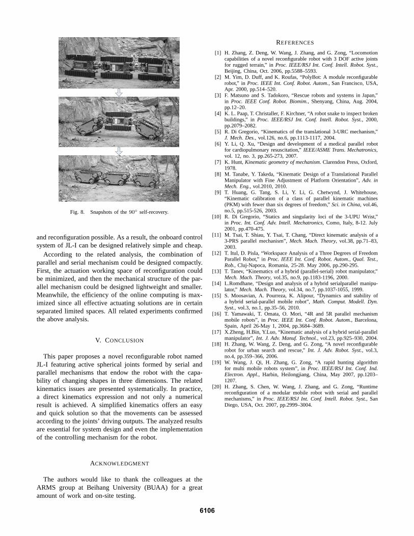
Fig. 8. Snapshots of the90∘ self-recovery.
and reconfiguration possible. As a result, the onboard controlsystem of JL-I can be designed relatively simple and cheap.
According to the related analysis, the combination ofparallel and serial mechanism could be designed compactly.First, the actuation working space of reconfiguration couldbe minimized, and then the mechanical structure of the par-allel mechanism could be designed lightweight and smaller.Meanwhile, the efficiency of the online computing is max-imized since all effective actuating solutions are in certainseparated limited spaces. All related experiments confirmedthe above analysis.
V. CONCLUSION
This paper proposes a novel reconfigurable robot namedJL-I featuring active spherical joints formed by serial andparallel mechanisms that endow the robot with the capa-bility of changing shapes in three dimensions. The relatedkinematics issues are presented systematically. In practice,a direct kinematics expression and not only a numericalresult is achieved. A simplified kinematics offers an easyand quick solution so that the movements can be assessedaccording to the joints’ driving outputs. The analyzed resultsare essential for system design and even the implementationof the controlling mechanism for the robot.
ACKNOWLEDGMENT
The authors would like to thank the colleagues at theARMS group at Beihang University (BUAA) for a greatamount of work and on-site testing.
REFERENCES
[1] H. Zhang, Z. Deng, W. Wang, J. Zhang, and G. Zong, “Locomotioncapabilities of a novel reconfigurable robot with 3 DOF active jointsfor rugged terrain,” inProc. IEEE/RSJ Int. Conf. Intell. Robot. Syst.,Beijing, China, Oct. 2006, pp.5588–5593.
[2] M. Yim, D. Duff, and K. Roufas, “PolyBot: A module reconfigurablerobot,” in Proc. IEEE Int. Conf. Robot. Autom., San Francisco, USA,Apr. 2000, pp.514–520.
[3] F. Matsuno and S. Tadokoro, “Rescue robots and systems inJapan,”in Proc. IEEE Conf. Robot. Biomim., Shenyang, China, Aug. 2004,pp.12–20.
[4] K. L. Paap, T. Christaller, F. Kirchner, “A robot snake toinspect brokenbuildings,” in Proc. IEEE/RSJ Int. Conf. Intell. Robot. Syst., 2000,pp.2079–2082.
[5] R. Di Gregorio, “Kinematics of the translational 3-URC mechanism,”J. Mech. Des., vol.126, no.6, pp.1113-1117, 2004.
[6] Y. Li, Q. Xu, “Design and development of a medical parallel robotfor cardiopulmonary resuscitation,”IEEE/ASME Trans. Mechatronics,vol. 12, no. 3, pp.265-273, 2007.
[7] K. Hunt, Kinematic geometry of mechanism. Clarendon Press, Oxford,1978.
[8] M. Tanabe, Y. Takeda, “Kinematic Design of a Translational ParallelManipulator with Fine Adjustment of Platform Orientation”, Adv. inMech. Eng., vol.2010, 2010.
[9] T. Huang, G. Tang, S. Li, Y. Li, G. Chetwynd, J. Whitehouse,“Kinematic calibration of a class of parallel kinematic machines(PKM) with fewer than six degrees of freedom,”Sci. in China, vol.46,no.5, pp.515-526, 2003.
[10] R. Di Gregorio, “Statics and singularity loci of the 3-UPU Wrist,”in Proc. Int. Conf. Adv. Intell. Mechatronics, Como, Italy, 8-12. July2001, pp.470-475.
[11] M. Tsai, T. Shiau, Y. Tsai, T. Chang, “Direct kinematic analysis of a3-PRS parallel mechanism”,Mech. Mach. Theory, vol.38, pp.71–83,2003.
[12] T. Itul, D. Pisla, “Workspace Analysis of a Three Degrees of FreedomParallel Robot,” inProc. IEEE Int. Conf. Robot. Autom., Qual. Test.,Rob., Cluj-Napoca, Romania, 25-28. May 2006, pp.290-295.
[13] T. Tanev, “Kinematics of a hybrid (parallel-serial) robot manipulator,”Mech. Mach. Theory, vol.35, no.9, pp.1183-1196, 2000.
[14] L.Romdhane, “Design and analysis of a hybrid serialparallel manipu-lator,” Mech. Mach. Theory, vol.34, no.7, pp.1037-1055, 1999.
[15] S. Moosavian, A. Pourreza, K. Alipour, “Dynamics and stability ofa hybrid serial-parallel mobile robot”,Math. Comput. Modell. Dyn.Syst., vol.3, no.1, pp.35–56, 2010.
[16] T. Yamawaki, T. Omata, O. Mori, “4R and 5R parallel mechanismmobile robots”, inProc. IEEE Int. Conf. Robot. Autom., Barcelona,Spain, April 26-May 1, 2004, pp.3684–3689.
[17] X.Zheng, H.Bin, Y.Luo, “Kinematic analysis of a hybridserial-parallelmanipulator”,Int. J. Adv. Manuf. Technol., vol.23, pp.925–930, 2004.
[18] H. Zhang, W. Wang, Z. Deng, and G. Zong, “A novel reconfigurablerobot for urban search and rescue,”Int. J. Adv. Robot. Syst., vol.3,no.4, pp.359–366, 2006.
[19] W. Wang, J. Qi, H. Zhang, G. Zong, “A rapid hunting algorithmfor multi mobile robots system”, inProc. IEEE/RSJ Int. Conf. Ind.Electron. Appl., Harbin, Heilongjiang, China, May 2007, pp.1203–1207.
[20] H. Zhang, S. Chen, W. Wang, J. Zhang, and G. Zong, “Runtimereconfiguration of a modular mobile robot with serial and parallelmechanisms,” inProc. IEEE/RSJ Int. Conf. Intell. Robot. Syst., SanDiego, USA, Oct. 2007, pp.2999–3004.
6106