efficient coupling and relaxed alignment tolerances in pigtailing of a laser diode using dual ball...
TRANSCRIPT

ARTICLE IN PRESS
OpticsOptikOptikOptik 120 (2009) 384–389
0030-4026/$ - se
doi:10.1016/j.ijl
�CorrespondE-mail addr
www.elsevier.de/ijleo
Efficient coupling and relaxed alignment tolerances in pigtailing
of a laser diode using dual ball lenses
Mohamed Fadhali�, Jasman Zainal, Yusof Munajat, Jalil Ali, Rosly Abdul Rahman
Institute of Advanced Photonics Sciences, Science Faculty, Universiti Teknologi Malaysia (UTM), 81310 Skudai, Johor Bahru,
Malaysia
Received 19 August 2007; accepted 27 October 2007
Abstract
In this paper, we report an efficient coupling scheme with relaxed misalignment tolerances. The proposed couplingscheme consists of two ball lenses of same diameter (1mm) and different refractive indices. The second ball lens whichis facing the fiber tip has a higher refractive index (1.833), whereas the first one which faces the laser diode has arefractive index of 1.5. Employing Gaussian and ABCD ray tracing optics, the theoretically obtained couplingefficiency can reach a unity with relaxed working distance (separation of the coupling system from the fiber tip) in therange between 1 and 4mm at some optimum positions of the coupling lenses with regard to each other and to the facetof the laser diode. It has been found that if the distance between the first ball lens and the laser diode (d1) is fixed at1.1mm, which is twice its focal length, the coupling efficiency and the working distance as well as the misalignmenttolerances are greatly affected by variation of the separation between the two ball lenses (s), and for this proposedcoupling scheme the highest coupling efficiency and largest working distance are obtained when s is in the range of0.3–0.35mm. Above and below this range there is a significant reduction in the values of the above-mentionedparameters. Experimentally, the Nd:YAG laser welding system has been used for the alignment and welding of thecoupling components in a butterfly configuration; the experimentally obtained coupling efficiency of the proposedcoupling system was around 75% with relaxed working distance. From the effect of lateral and angular offsets oncoupling efficiency, it is clearly noticed that the mode field of laser diode is transformed from elliptical into circular andhence effectively matched with that of the single-mode fiber.r 2007 Elsevier GmbH. All rights reserved.
Keywords: Laser welding; Coupling efficiency; Ball lenses; Misalignment tolerances
1. Introduction
Laser diode transmitter modules are packaged in threeconfigurations, butterfly, TO-can (coaxial) and dual inline. The common configuration for laser diode trans-mitters in optical communications is the butterfly
e front matter r 2007 Elsevier GmbH. All rights reserved.
eo.2007.10.005
ing author. Tel.: +7 5534110; fax: +75566162.
ess: [email protected] (M. Fadhali).
configuration. Most of the cost of these modules is dueto the process of packaging, which includes the couplingof laser diode to a single mode fiber via certain opticalcoupling schemes and the firm attachment of allcomponents at their optimum positions inside the module[1,2]. Butt or direct coupling of laser diode into single-mode fiber was found to be inefficient (�5–20%), withvery tight misalignment tolerances. A lot of publishedwork on employing different types of microlenses
ARTICLE IN PRESSM. Fadhali et al. / Optik 120 (2009) 384–389 385
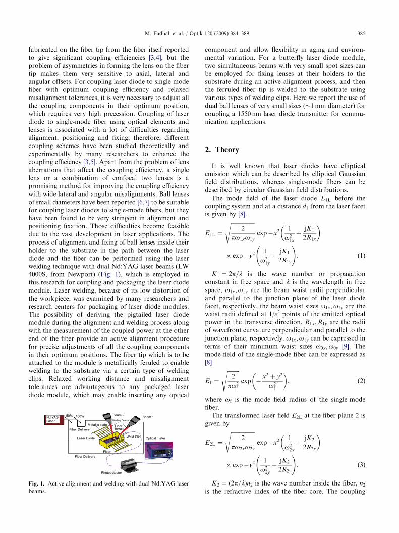
fabricated on the fiber tip from the fiber itself reportedto give significant coupling efficiencies [3,4], but theproblem of asymmetries in forming the lens on the fibertip makes them very sensitive to axial, lateral andangular offsets. For coupling laser diode to single-modefiber with optimum coupling efficiency and relaxedmisalignment tolerances, it is very necessary to adjust allthe coupling components in their optimum position,which requires very high precession. Coupling of laserdiode to single-mode fiber using optical elements andlenses is associated with a lot of difficulties regardingalignment, positioning and fixing; therefore, differentcoupling schemes have been studied theoretically andexperimentally by many researchers to enhance thecoupling efficiency [3,5]. Apart from the problem of lensaberrations that affect the coupling efficiency, a singlelens or a combination of confocal two lenses is apromising method for improving the coupling efficiencywith wide lateral and angular misalignments. Ball lensesof small diameters have been reported [6,7] to be suitablefor coupling laser diodes to single-mode fibers, but theyhave been found to be very stringent in alignment andpositioning fixation. Those difficulties become feasibledue to the vast development in laser applications. Theprocess of alignment and fixing of ball lenses inside theirholder to the substrate in the path between the laserdiode and the fiber can be performed using the laserwelding technique with dual Nd:YAG laser beams (LW4000S, from Newport) (Fig. 1), which is employed inthis research for coupling and packaging the laser diodemodule. Laser welding, because of its low distortion ofthe workpiece, was examined by many researchers andresearch centers for packaging of laser diode modules.The possibility of deriving the pigtailed laser diodemodule during the alignment and welding process alongwith the measurement of the coupled power at the otherend of the fiber provide an active alignment procedurefor precise adjustments of all the coupling componentsin their optimum positions. The fiber tip which is to beattached to the module is metallically feruled to enablewelding to the substrate via a certain type of weldingclips. Relaxed working distance and misalignmenttolerances are advantageous to any packaged laserdiode module, which may enable inserting any optical
Nd:YAGLaser
50% 100%
Fiber Delivery
Fiber Delivery
Laser Diode
Fiber
Fiberferrule
Weld Clip Optical meter
Photodetector
Metallic plate
Beam 2Beam 1
Fig. 1. Active alignment and welding with dual Nd:YAG laser
beams.
component and allow flexibility in aging and environ-mental variation. For a butterfly laser diode module,two simultaneous beams with very small spot sizes canbe employed for fixing lenses at their holders to thesubstrate during an active alignment process, and thenthe ferruled fiber tip is welded to the substrate usingvarious types of welding clips. Here we report the use ofdual ball lenses of very small sizes (�1mm diameter) forcoupling a 1550 nm laser diode transmitter for commu-nication applications.
2. Theory
It is well known that laser diodes have ellipticalemission which can be described by elliptical Gaussianfield distributions, whereas single-mode fibers can bedescribed by circular Gaussian field distributions.
The mode field of the laser diode E1L before thecoupling system and at a distance d1 from the laser facetis given by [8].
E1L ¼
ffiffiffiffiffiffiffiffiffiffiffiffiffiffiffiffiffi2
po1xo1y
sexp�x2 1
o21x
þjK1
2R1x
� �
� exp�y2 1
o21y
þjK1
2R1y
!. ð1Þ
K1 ¼ 2p=l is the wave number or propagationconstant in free space and l is the wavelength in freespace, o1x;o1y are the beam waist radii perpendicularand parallel to the junction plane of the laser diodefacet, respectively, the beam waist sizes o1x;o1y are thewaist radii defined at 1/e2 points of the emitted opticalpower in the transverse direction. R1x;R1y are the radiiof wavefront curvature perpendicular and parallel to thejunction plane, respectively. o1x;o1y can be expressed interms of their minimum waist sizes o0x;o0y [9]. Themode field of the single-mode fiber can be expressed as[8]
Ef ¼
ffiffiffiffiffiffiffiffiffi2
po2f
sexp �
x2 þ y2
o2f
� �, (2)
where of is the mode field radius of the single-modefiber.
The transformed laser field E2L at the fiber plane 2 isgiven by
E2L ¼
ffiffiffiffiffiffiffiffiffiffiffiffiffiffiffiffiffi2
po2xo2y
sexp�x2 1
o22x
þjK2
2R2x
� �
� exp�y2 1
o22y
þjK2
2R2y
!. ð3Þ
K2 ¼ ð2p=lÞn2 is the wave number inside the fiber, n2is the refractive index of the fiber core. The coupling

ARTICLE IN PRESSM. Fadhali et al. / Optik 120 (2009) 384–389386
efficiency is expressed by the overlap integral [3,4,6,7,10]
Z ¼
RRE2Lðx; yÞE
�f ðx; yÞdxdyRR
jE2Lðx; yÞj2 dxdy �
RRjEf ðx; yÞj
2 dxdy. (4)
This integral can be solved to obtain
Z ¼ 4o2f =o2xo2y 1þ o2
f =o22x
� �2þ k2
2o4f =4R2
2x
� �h i�1=2� 1þ o2
f =o22y
� �2þ k2
2o4f =4R2
2y
� � �1=2ð5Þ
The ABCD ray-tracing matrix of the dual-ball lensesconfiguration shown in Fig. 2 can be easily formulatedto obtain the expressions for A, B, C and D, which willbe used in the expressions of the transformed beamwaist and wavefront curvature radii [3] as follows:
ðw2x;2yÞ2¼ðAþ B=R1x;1yÞ
2ðw1x;1yÞ
4þ ðl1BÞ
2
nðAD� BCÞðo1x;1yÞ2
, (6)
R2x;2y ¼ðAþ B=R1x;1yÞ
2ðo1x;1yÞ
4þ ðl1BÞ2
ðAþ B=R1x;1yÞðC þD=R1x;1yÞðo1x;1yÞ4þ ðl21BDÞ
,
(7)
where l1 ¼ l=pn1, n1 is the refractive index of themedium before the coupling system. The ABCD raytracing matrix of the above system is given as
M ¼1 d2
0 1
����������
1 0
ðnl � n0Þ=Rln0 nl=n0
����������
�1 2Rl
0 1
����������
1 0
ðn0 � nlÞ=Rlnl n0=nl
����������1 s
0 1
����������
�1 0
ðnm � n0Þ=Rmn0 nm=n0
����������1 2Rm
0 1
����������
�1 0
ðn0 � nmÞ=Rmnm n0=nm
����������1 d1
0 1
����������. ð8Þ
The matrix is solved to obtain the final matrix
A B
C D
��������.
From the values of A, B, C and D we calculateo2x;o2y;R2x and R2y; and then substitute it in Eq. (5).
When considering the possible lateral and angularoffsets, analytical analysis suggests that the coupling
LDSMF
d1d2Ball lens 1
Ball lens 2
Rm
R1nm n1
S
Fig. 2. Dual ball lenses coupling of laser diode to single-mode
fiber.
efficiency with lateral offset is given as
Z0 ¼ Z exp�2d2
x=o22x
½ð1þ o2f =o
22xÞ
2ðk2
2o4f =4R2
2x�1=2
!
� exp�2d2
y=o22y
½ð1þ o2f =o
22yÞ
2þ ðk2
2o4f =4R2
2y�1=2
!, ð9Þ
where dx is the lateral offset on the x-axis and dy is thelateral offset on the y-axis.
And for the case of estimating the angular offset, thecoupling efficiency is given by
Z00 ¼ Z exp�k22o
2f
2
f2x
ð1þ o2f =o
22xÞ
2þ ðk2
2o4f =4R2
2x� �1=2
0B@
þf2
y
ð1þ o2f =o
22yÞ
2þ ðk2
2o4f =4R2
2yÞ
h i�1=21CA,
ð10Þ
where fx;fy are the tilt angles in the x and y directions,respectively.
3. Experimental method
In our research, we use the system of laser weld(LW4000S), which includes an Nd:YAG laser with duallaser beams, welding workstation and motorized stagefor laser diode module housing, which is connected to alaser diode controller for driving the laser diode module,with active alignment facilities, i.e., during the alignmentof a laser diode transmitter module, the systemcontinuously measures the output power at the freeend of the fiber to determine the coupling efficiency.A machine vision system pre-positions the housing, and,after the system locates the light in the fiber, alignmentroutines determine the optimum coupling position. Thecoupling parts are then fixed using two simultaneouslaser beams from the Nd:YAG laser schematicallyshown in Fig. 1. The laser pulse energy and durationas well as the sequence of the spot welds have to beadjusted to compensate the expected deformation andguarantee a well-performing welding joint withoutintroducing unnecessary heat. The spot welds are placedsymmetrically to reduce thermal influence. This processcompensates for the stress introduced by the welds. Thealignment process for all components and the spot-weldquality are monitored by CCD cameras on the weldingoptics. The welding laser includes a pilot laser beam,which simplifies positioning the spots and the develop-ment of the welding process. In addition, the spot weldscan be viewed to determine optimum welding para-meters.

ARTICLE IN PRESSM. Fadhali et al. / Optik 120 (2009) 384–389 387
Two ball lenses of diameter ¼ 1mm and differentrefractive index are used. The first one facing the laserdiode has a refractive index of nm ¼ 1.5 made of BK7,Grade A fine annealed glass. The other lens facing thefiber tip has a refractive index of nl ¼ 1.8333 made ofLaSF N9, grade A, fine annealed optical glass and hasbeen used for coupling 1550 nm laser diode into single-mode fiber with a core radius of 4 mm. Using twopneumatic grippers, one for gripping the ferruled fibertip at the position of maximum coupling power and theother for gripping the first lens facing the laser diode(collimating lens), the process of realignment andadjustment is performed before using laser welding tofix the lens in its holder to the substrate. The process isrepeated for the second lens (focusing lens). Beforewelding the second lens, the alignment process andadjustment of the separations between the two lenses, aswell as between lenses and the laser diode or fiber tip,has to be performed to assure maximum couplingefficiency with relaxed misalignment tolerances.
1
0.9
0.8
0.7
0.6
0.5
0.4
0.3
0.2
0.1
00 0.5 1 1.5 2 2.5 3 3.5 4
x 10-3Ball lens to Fiber separation d2 (m)
No
rma
lize
d C
ou
plin
g E
ffic
ien
cy η
Fig. 4. Effect of variation of working distance on the coupling
efficiency (experimentally).
4. Results and discussion
The obtained results show that coupling of laser diodeto single-mode fiber using double-ball lenses is moreefficient with large working distance compared withother coupling schemes; moreover, the use of low-costball lenses in laser diode coupling will contribute toreducing the cost of its manufacturing. The simulationresults, Fig. 3, show that by fixing the laser to the firstlens separation (d1) at 1.1mm (which is the optimumdistance) and for a divergence ratio yx=yy ¼ 8=33, thecoupling efficiency and the working distance (fiber tip tosecond lens separation d2) can be controlled by variationof the separation between the two ball lenses (s). It hasbeen found that at s ¼ 0.35mm the coupling efficiency ismaximum at d2 ¼ 1.3mm, with a range of workingdistance d2 between 0.8 and 2mm.
0 0.5 1 1.5 2 2.5 3 3.5 4
x 10-3
0
0.1
0.2
0.3
0.4
0.5
0.6
0.7
0.8
0.9
1
Lens to Fiber Separation d2 (m)
No
rma
lize
d C
ou
plin
g E
ffic
ien
cy (
η)
s=0.25mm
s=0.3mm
s=0.35mm
s=0.4mm
s=0.45mmθx/θy= 8/33
Fig. 3. Effect of variation of working distance on the coupling
efficiency for different separations between the ball lenses.
At s ¼ 0.3mm the working distance is greatly relaxedwithin the range of 1–4mm, with considerably lowreduction in the coupling efficiency. As it is clear fromFig. 3, outside the range of s ¼ 0.3–0.35mm thecoupling efficiency as well as the working distance aregreatly reduced above or below this range.
The experimentally obtained results, Fig. 4, for twoball lenses with d1 ¼ 2mm and s ¼ 1mm show that themaximum coupling efficiency is around 75% at d2 ¼ 2mm; the working distance can be between 0.8 and1.5mm with some reduction in the coupling efficiency. Itwas very difficult to fix the lenses at a very tight distanceas those used in the simulations, but the possibility ofobtaining similar results exists if the experimentaltechnique can be developed to attach lenses within verysmall distances.
By studying the effects of lateral and angular offsetson the coupling efficiency, we found that using double-ball lenses coupling scheme is suitable to convert theelliptical laser beam distribution to nearly circulardistribution, which is clear from comparing the effect
-2 -1.5 -1 -0.5 0 0.5 1 1.5 2
x 10-5
0
0.1
0.2
0.3
0.4
0.5
0.6
0.7
0.8
0.9
1
Lateral Offset dx , dy (m)
No
rma
lize
d C
ou
plin
g E
ffic
ien
cy (
η) X-axis
Y-axis
d1= 1.1 mm
d1= 1.5 mm
s = 0.35 mm
θx/θy= 8/33
Fig. 5. Effect of lateral displacement on the coupling efficiency
(using double-ball lenses).
ARTICLE IN PRESS
0.8
0.9
1
ien
cy (
η)
X-axisY-axis
d1= 1.1mm
d = 1.5mm
M. Fadhali et al. / Optik 120 (2009) 384–389388
of lateral offsets in x and y directions on the couplingefficiency, wherein we can see that for the case ofdouble-ball lenses the offset of both x and y directions,
-1 -0.8 -0.6 -0.4 -0.2 0 0.2 0.4 0.6 0.8 1
x 10-5
0
0.05
0.1
0.15
0.2
0.25
0.3
0.35
Lateral Offset dx, dy (m)
No
rma
lize
d C
ou
plin
g E
ffic
ien
cy (
η) X-axis
Y-axis
θx /θy= 8/33
Fig. 6. Effect of lateral displacement on the coupling efficiency
(Butt coupling).
-2 -1 0 1 2
x 10-5
0
0.1
0.2
0.3
0.4
0.5
0.6
0.7
Lateral Offset dx , dy (m)
No
rma
lize
d C
ou
plin
g E
ffic
ien
cy (
η)
X-axis
Y-axis
θx/θy=8/33
Single Ball lens
Fig. 7. Effect of lateral displacement on the coupling efficiency
(single-ball lens).
100%
80%
60%
40%
20%
0-20 -10 0.0 10 20
Lateral Offset (μm)
Couple
d P
ow
er
(%)
X-axis
Y-axis
Fig. 8. The variation of coupling efficiency with the lateral
offsets (double-ball lenses, exp.).
-20 -15 -10 -5 0 5 10 15 200
0.1
0.2
0.3
0.4
0.5
0.6
0.7
Angular Offset (Degree)
No
rma
lize
d C
ou
plin
g E
ffic 2
s = 0.35mmθx/θy=8/33
Fig. 9. The variation of coupling efficiency with the angular
offsets.
Laser diode
Coupling lenses
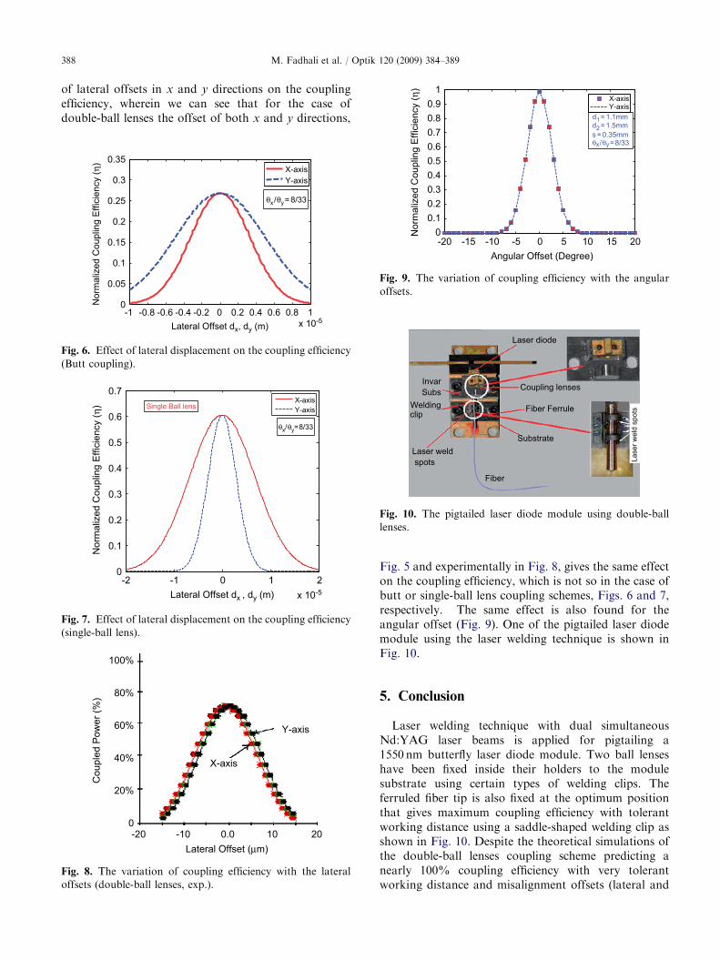
Fiber Ferrule
Fiber
Laser weld
spots
clipWelding
Substrate
Subs
Invar
Laser
weld
spots
Fig. 10. The pigtailed laser diode module using double-ball
lenses.
Fig. 5 and experimentally in Fig. 8, gives the same effecton the coupling efficiency, which is not so in the case ofbutt or single-ball lens coupling schemes, Figs. 6 and 7,respectively. The same effect is also found for theangular offset (Fig. 9). One of the pigtailed laser diodemodule using the laser welding technique is shown inFig. 10.
5. Conclusion
Laser welding technique with dual simultaneousNd:YAG laser beams is applied for pigtailing a1550 nm butterfly laser diode module. Two ball lenseshave been fixed inside their holders to the modulesubstrate using certain types of welding clips. Theferruled fiber tip is also fixed at the optimum positionthat gives maximum coupling efficiency with tolerantworking distance using a saddle-shaped welding clip asshown in Fig. 10. Despite the theoretical simulations ofthe double-ball lenses coupling scheme predicting anearly 100% coupling efficiency with very tolerantworking distance and misalignment offsets (lateral and

ARTICLE IN PRESSM. Fadhali et al. / Optik 120 (2009) 384–389 389
angular), the experimentally obtained coupling effi-ciency is around 75% due to some practical limitationsregarding the separation between the ball lenses that wasnot easy to be brought to the ranges used in simulations,and there are some losses due to reflections andabsorption by the coupling media which are ignored inthe simulation. The experimentally obtained workingdistance and misalignment tolerances are tolerant, asshown in Figs. 4 and 8, respectively.
By comparing the results of lateral and angular offsetsfor Butt, single-ball lens and double-ball lens, it is clearlynoticed that double-ball lenses give the maximumcoupling efficiency and also that it is very effective inmode matching between the elliptical mode of the laserdiode and circular mode of the single-mode fiber, i.e.,since the offset in the x-axis has the same effect as that inthe y-axis as shown in Figs. 5, 8 and 9, the transforma-tion of the elliptical mode has been effectively trans-formed to a circular one.
Acknowledgment
The author would like to thank the Government ofMalaysia, Universiti Teknologi Malaysia, Ibb Univer-sity, Yemen, and International Development Bank fortheir support in this research.
References
[1] B. Valk, R. Battig, O. Anthamatran, Laser welding for
fiber pigtailing with long-term stability and submicron
accuracy, Opt. Eng. 34 (1995) 2675–2682.
[2] Soon Jang, Automation Manufacturing system technol-
ogy for Optoelectronic Devices Packaging, Electronic
Components and Technology Conference, IEEE, 2000.
[3] S. Gangopdhyay, S.N. Sarker, Laser diode to single-fiber
excitation via hyperbolic lens on the fiber tip: formulation
of ABCD matrix and efficiency computation, J. Opt.
Commun. 132 (1996) 55–60.
[4] R.A. Modavis, T.W. Webb, Anamorphic microlens for
laser diode to single-mode fiber coupling, IEEE Photon.
Technol. Lett. 7 (7) (1995) 798–800.
[5] C.A. Edwards, et al., Ideal microlenses for laser-to-fiber
coupling, J. Lightwave Technol. 11 (1993) 252–257.
[6] K. Holger, D. Karsten, Loss analysis of laser diode to
single-mode fiber couplers with glass spheres or silicon
plano-convex lenses, IEEE J. Lightwave Technol. 8 (5)
(1990) 739–747.
[7] L.A. Reith, et al., Relaxed-tolerance optoelectronic
device packaging, J. Lightwave Technol. 9 (4) (1991)
477–487.
[8] B.E. Saleh, M.C. Teich, Fundamentals of Photonics,
Wiley, USA & Canada, 1991.
[9] R.D. Guenther, Modern Optics, Wiley, Canda, 1990.
[10] Z. Tang, R. Zhang, F.G. Shi, Effects of angular
misalignments on fiberoptic coupling alignment automa-
tion, J. Opt. Commun. 196 (2001) 173–180.