efficient 3d data representation for biometric applications hassan ugail and eyad elyan school of...
TRANSCRIPT

Efficient 3D Data Representation for Biometric Applications
Hassan Ugail and Eyad Elyan
School of Informatics University of Bradford
United Kingdom

Distributed Virtual Environments research Distributed Virtual Environments research
Research in the area of geometric modelling, virtual environments, virtual simulations, 3D modelling and rendering for entertainment and computer games.
11 members of staff,Several post-docsMany PhD and masters students.
Resources include: - 15 camera Vicon motion capture system (same as that used to create Lord of the rings movie. )
- A high end render-farm for rendering high quality geometric scenes.
example

Thanks Thanks
• Modelling and Animation, EPSRC grant value £281,500 + Support from Alias.
• Biharmonic Polynomial Surfaces. EPSRC grant value £10,070.
• 3D FACIS: Higher Education Innovation Fund (HEIF) grant, value £70,000.
• Magic Curves 3D for MAYA - University of Bradfordgrant, value £15,000.

We discuss techniques for representing 3D data for biometric applications.
e.g. It is a common problem to construct a smooth surface for some given point cloud data to adequately describe the shape. (e.g. scan data of a human face)
IntroductionIntroduction

1. Be able to model complex shapes (e.g. human face, body pose, shape of hand, DNA etc.)
2. Be able to parameterise the data (i.e. describe the data using a small parameter set of the underlying representation).
3. Efficient data storage (e.g. point cloud data from a 3D scan face is around 1MB which cannot be used to perform efficient searches)
Requirements of a 3D representation technique Requirements of a 3D representation technique

Existing Methods Existing Methods
A number of techniques currently exist for 3D data representation.
For example,
- Spline based techniques
- Subdivision techniques

Spline based techniques Spline based techniques
Uses polynomial interpolations, For example,
Bézier surfaces
NURBS
Problem: too many control points (difficult to parameterise the geometry)

Subdivision techniques Subdivision techniques
Uses simple set of local rules and can create geometry of arbitrary topology
Problem: generating smooth surfaces is an issue

Partial Differential Equations for 3D Partial Differential Equations for 3D Data Representation Data Representation

Heat
Heat
Imagine the steady state heat distribution of an insulated metal bar
- internal temperature depends on heat applied at the boundary- heat distribution is constant throughout at steady state - temperature will not exceed that supplied at the boundaries
02
2
2
2
2
2
z
H
y
H
x
HMathematically this can be modelled using Laplace Equation
The idea of Partial Differential Equations (PDEs) The idea of Partial Differential Equations (PDEs)

Now if we simply solve Laplace Equation with a set of boundary conditions and plot the resulting solution we will get a surface.
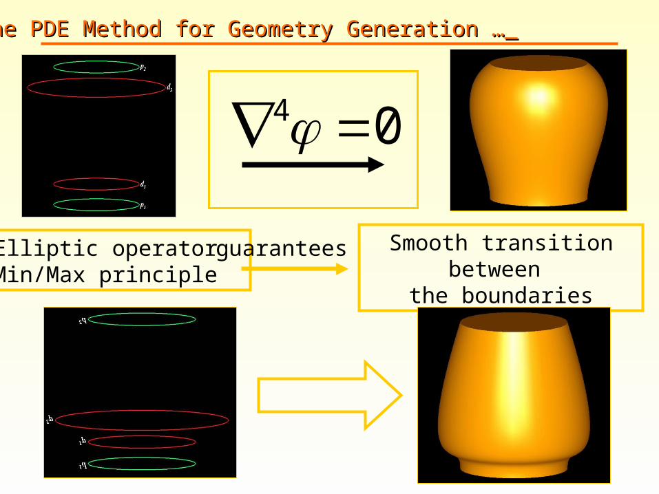
We know that: - surface shape depends on the shape of the boundary- surface is a smooth transition between the boundaries- internal surface points is less or equal to the boundary (a.k.a Min-Max principle)
The idea of Partial Differential Equations (PDEs) The idea of Partial Differential Equations (PDEs)
04
Elliptic operator Min/Max principle
guarantees Smooth transition between the boundaries
The PDE Method for Geometry Generation …The PDE Method for Geometry Generation …

u
v x
y
z
X(u,v)
The PDE Method for Geometry Generation The PDE Method for Geometry Generation
X(u,v) = (x(u,v), y(u,v), z(u,v))
32 )( ER
NoteThe boundary in the (u,v) space is mapped to that in (x,y,z)

n
X
Usually we choose the 4th order elliptic PDE:
0),(2
2
22
2
2
vuXv
au
Boundary conditions are:
variations of ),( vuX and along
• Boundary value approach
• Global smoothing approach
• Small set of design parameters
Advantages
a is a special parameter known as the smoothing parameter

Position Curves curves at u=0 and u=10<=v<=2
u=0
u=1
p1
p2
Derivative Curves
svdvpn
X)]()([
Both size and directioncan be controlled
Interactive Definition of Boundary Conditions Interactive Definition of Boundary Conditions
d2
P2
u=0
d2
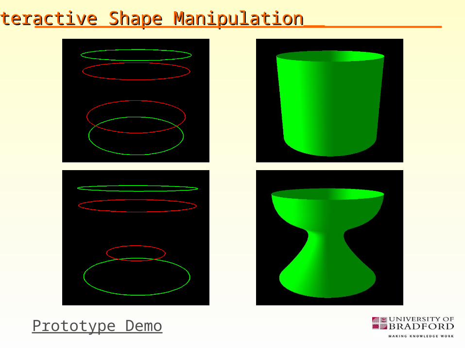
Interactive Shape ManipulationInteractive Shape Manipulation
P2
Prototype Demo

u=0
d2
Example PDE GeometryExample PDE Geometry
P2

Biometric Application: Biometric Application: 3D Facial data representation and recognition3D Facial data representation and recognition

Shape reconstruction using the Biharmonic Shape reconstruction using the Biharmonic EquationEquation
For shape reconstruction we use the fourth order PDE based on the Laplace equation.
0),(
2
2
2
2
2
vuXvu
Boundary conditions are:
)(),1(
)(),(
)(),(
)(),0(
1
0
vPvX
vPvuX
vPvuX
vPvX
tt
ss
Note: the PDE is solved explicitly.

Algorithm for reconstructionAlgorithm for reconstruction
For a given shape (e.g. point cloud data).
1. Extract a series of profile curves
2. Arrange the curves in groups of four
3. Assign each group of four curves as boundary conditions for the 4th order PDE
4. Generate a continuous surface

Example Example
Boundary curves Resulting surface

Results Results
Original surface Reconstructed surfaceCurves extracted
Example of reconstruction – 3D face example 1

Results Results
Example of reconstruction – 3D face example 2
Original surface Reconstructed surface
Curves extracted

Results Results
Comparison
As one can see there is good agreement between the original and
reconstructed face.
Original data:
triangulated (green)

Parametric Representation and manipulation Parametric Representation and manipulation
Define a face using a series of
parameters (i.e. a handful of
measures)
1. Define a set of facial features on a template face
2. For every facial feature allocate the set of controls that define its topology and local geometry
3. Define a set of parameters for every feature based on the previous allocated points
4. Adjust these parameters to generate a new face.

Parametric Representation and manipulation Parametric Representation and manipulation
The Generic
template can be
updated based
on the chosen
parameters.
This has applications in other areas. e.g. facial animation

Efficient data storage for the 3D faceEfficient data storage for the 3D face
Our PDE based facial model based on curves which identify key facial
Features enables facial data to be stored very efficiently.
Typical 3D facial scan over 1MB data
PDE model typically 30KB
Face can be saved generated and re-generated very efficiently

Raw data processing and face characterisationRaw data processing and face characterisation
Processing raw data (from scan)
includes
1. Loading the Original Mesh
2. Neutralising the face (i.e. place it in a Cartesian coordinate frame)
3. Extracting a set of boundary curves that represent the vertical profiles of the face

Automatic facial feature identificationAutomatic facial feature identification
Key features such as
Nose tip, nose bridge,eye centre etc are identified.

Facial authentication/detectionFacial authentication/detection
• Define a set of parameters (based on the PDE boundary curves) within the central region.
• These parameters are unique to each face and are used to uniquely identify each face.

Systems disposalSystems disposal
• Many interested commercial parties.
• System was on trial at London Heathrow new Terminal 5. Outperformed Iris based detection.

Conclusion Conclusion
We have discussed techniques for 3D data representation using Partial Differential Equation. These techniques allow us to
• generate smooth surfaces for the given data
• efficiently parameterise the data set
• efficiently store the data
An example, based on 3D face modelling and recognition has been discussed.

Further Readings Further Readings
H. Ugail, M.I.G. Bloor, and M.J. Wilson, Techniques for Interactive Design Using the PDE Method, ACM Transactions on Graphics, 18(2), 195-212, (1999).
J. Monterde and H. Ugail, A General 4th-Order PDE Method to Generate Bézier Surfaces from the Boundary, Computer Aided Geometric Design, 23 (2): 208-225, (2006).
H. Ugail, 3D Facial Data Fitting using the Biharmonic Equation, in Visualization, Imaging and Image Processing, J.J. Villanueva (ed.), ACTA Press ISBN: 0-88986-598-1, pp. 302-307. (2006).
www.ugail.org

Questions ? Questions ?