effects of the uoe/uoc pipe manufacturing processes...
TRANSCRIPT

ARTICLE IN PRESS
0020-7403/$ - se
doi:10.1016/j.ijm
�CorrespondE-mail addr
International Journal of Mechanical Sciences 49 (2007) 533–553
www.elsevier.com/locate/ijmecsci
Effects of the UOE/UOC pipe manufacturing processeson pipe collapse pressure
M.D. Herynk, S. Kyriakides�, A. Onoufriou, H.D. Yun
Research Center for Mechanics of Solids, Structures and Materials, WRW 110, C0600, The University of Texas at Austin, Austin, TX 78712, USA
Received 30 May 2006; received in revised form 10 October 2006; accepted 16 October 2006
Available online 8 December 2006
Abstract
Large-diameter pipes used in offshore applications are commonly manufactured by cold-forming plates through the UOE process. The
plate is crimped along its edges, formed into a U-shape and then pressed into an O-shape between two semicircular dies. The pipe is
welded closed and then circumferentially expanded to obtain a highly circular shape. Collapse experiments have demonstrated that these
steps, especially the final expansion, degrade the mechanical properties of the pipe and result in a reduction in its collapse pressure
upwards of 30%. In this study the UOE forming process has been modeled numerically using a 2-D finite element model. The model can
assess the effects of press parameters of each forming step on the final geometry and mechanical properties of the pipe. The final step
involves simulation of pipe collapse under external pressure in order to quantify the effect of the forming variables on its performance.
Examples of these variables are the radii of the forming dies, the chosen displacements of the dies, the compression strain in the O-step,
the expansion strain, etc. An extensive parametric study of the problem has been conducted, through which ways of optimizing the
process for improved collapse performance have been established. For example, it was found that optimum collapse pressure requires a
tradeoff between pipe shape (ovality) and material degradation. Generally, increase in the O-strain and decrease in the expansion strain
improve the collapse pressure. Substituting the expansion with compression can not only alleviate the UOE collapse pressure degradation
but can result in significant increases in collapse performance.
r 2006 Elsevier Ltd. All rights reserved.
Keywords: UOE-pipe; UOC-pipe; Collapse pressure
1. Introduction
Pipes used to transport oil and gas larger thanapproximately 16 in in diameter are commonly manufac-tured by cold forming of 40–60 ft (12.2–18.3m) long plates.The plates are formed into a circular cylindrical shapethrough the four mechanical steps shown schematically inFig. 1. The plate edges are first crimped into circular arcs(Fig. 1a). The plate is then formed into a U-shape in the‘‘U-press’’ (Fig. 1b). It is then pressed into a circular shapein the ‘‘O-press’’ (Fig. 1c). The seam is subsequently weldedusing submerged arc welding. In the final step the pipe ismechanically expanded (Fig. 1d) as a means of final sizingand improving its circularity. The name UOE stems fromthe initials of the last three of these mechanical steps.
e front matter r 2006 Elsevier Ltd. All rights reserved.
ecsci.2006.10.001
ing author. Fax: +1512 471 5500.
ess: [email protected] (S. Kyriakides).
UOE pipe has been widely used for land pipelines,including the Trans-Alaska and Trans-Siberia pipelines. Inthe last 15 years it has also been increasingly used inoffshore applications where collapse under external pres-sure is a primary design consideration and, as a result, highcircularity is required [1–3]. Modern UOE pipe mills arecapable of delivering pipes of high circularity with typicalovality values ranging between 0.15% and 0.35%. Despitetheir low ovalities, experiments have demonstrated that thecollapse pressure of such pipes can be significantly lowerthan that of corresponding seamless pipes. For typical pipegeometries and plate material properties, the degradationin collapse pressure of UOE pipe can exceed 30%.The reasons behind this degradation in collapse pressure
were first identified in Ref. [4]. It was demonstrated that thefour cold-forming steps, in particular the final expansion,introduce changes to the compressive stress–strain responseof the pipe in the circumferential direction. This is

ARTICLE IN PRESS
Fig. 1. Schematic and main parameters of UOE and UOC forming steps. (a) Crimping press, (b) U-press, (c) O-press, (d) expansion and (e) compression.
0
20
40
60
80
0 0.2 0.4 0.6 0.8 10
200
400
600
(ksi)
ε (%)
Outer
(MPa)
InnerPlate
X-70
D = 24.0 in
t = 1.273 in
Outer
Inner
σσ
Fig. 2. Comparison of plate stress–strain response and responses from
transverse UOE specimens tested in compression.
M.D. Herynk et al. / International Journal of Mechanical Sciences 49 (2007) 533–553534
illustrated in Fig. 2 for a 24 in X-70 pipe with wallthickness of 1.273 in (32.33mm). Compressive stress–strainresponses from circumferential specimens extracted fromtwo locations through the thickness, and the stress–strainresponse of the original plate are shown. The mechanicalwork has rounded the stress–strain responses significantlyand lowered the stress in the critical strain range forcollapse of 0.3–0.5%. The collapse pressure of the as-received pipe was calculated to be 5059 psi (348.9 bar). Bycontrast, when the same pipe geometry is assigned the platemechanical properties, the collapse pressure becomes7508 psi (517.8 bar), an increase of 48%.
This high level of degradation in collapse pressure wasfirst demonstrated in full-scale tests performed in support ofthe Oman–India pipeline [5]. Eleven collapse tests wereperformed on 20 in pipe supplied by three differentmanufacturers (X65 nominal, t ¼ 1.125 in—28.58mm). Ninepipes were tested in the as-received state. Their collapse
ARTICLE IN PRESSM.D. Herynk et al. / International Journal of Mechanical Sciences 49 (2007) 533–553 535
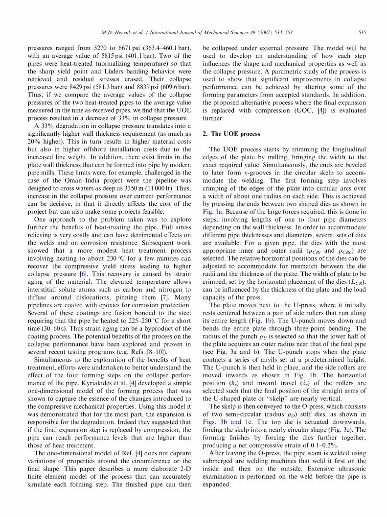
pressures ranged from 5270 to 6671 psi (363.4–460.1bar),with an average value of 5815 psi (401.1 bar). Two of thepipes were heat-treated (normalizing temperature) so thatthe sharp yield point and Luders banding behavior wereretrieved and residual stresses erased. Their collapsepressures were 8429psi (581.3 bar) and 8839psi (609.6bar).Thus, if we compare the average values of the collapsepressures of the two heat-treated pipes to the average valuemeasured in the nine as-received pipes, we find that the UOEprocess resulted in a decrease of 33% in collapse pressure.
A 33% degradation in collapse pressure translates into asignificantly higher wall thickness requirement (as much as20% higher). This in turn results in higher material costsbut also in higher offshore installation costs due to theincreased line weight. In addition, there exist limits in theplate wall thickness that can be formed into pipe by modernpipe mills. These limits were, for example, challenged in thecase of the Oman–India project were the pipeline wasdesigned to cross waters as deep as 3350m (11 000 ft). Thus,increase in the collapse pressure over current performancecan be decisive, in that it directly affects the cost of theproject but can also make some projects feasible.
One approach to the problem taken was to explorefurther the benefits of heat-treating the pipe. Full stressrelieving is very costly and can have detrimental effects onthe welds and on corrosion resistance. Subsequent workshowed that a more modest heat treatment processinvolving heating to about 230 1C for a few minutes canrecover the compressive yield stress leading to highercollapse pressure [6]. This recovery is caused by strainaging of the material. The elevated temperature allowsinterstitial solute atoms such as carbon and nitrogen todiffuse around dislocations, pinning them [7]. Manypipelines are coated with epoxies for corrosion protection.Several of these coatings are fusion bonded to the steelrequiring that the pipe be heated to 225–250 1C for a shorttime (30–60 s). Thus strain aging can be a byproduct of thecoating process. The potential benefits of the process on thecollapse performance have been explored and proven inseveral recent testing programs (e.g. Refs. [8–10]).
Simultaneous to the exploration of the benefits of heattreatment, efforts were undertaken to better understand theeffect of the four forming steps on the collapse perfor-mance of the pipe. Kyriakides et al. [4] developed a simpleone-dimensional model of the forming process that wasshown to capture the essence of the changes introduced tothe compressive mechanical properties. Using this model itwas demonstrated that for the most part, the expansion isresponsible for the degradation. Indeed they suggested thatif the final expansion step is replaced by compression, thepipe can reach performance levels that are higher thanthose of heat treatment.
The one-dimensional model of Ref. [4] does not capturevariations of properties around the circumference or thefinal shape. This paper describes a more elaborate 2-Dfinite element model of the process that can accuratelysimulate each forming step. The finished pipe can then
be collapsed under external pressure. The model will beused to develop an understanding of how each stepinfluences the shape and mechanical properties as well asthe collapse pressure. A parametric study of the process isused to show that significant improvements in collapseperformance can be achieved by altering some of theforming parameters from accepted standards. In addition,the proposed alternative process where the final expansionis replaced with compression (UOC, [4]) is evaluatedfurther.
2. The UOE process
The UOE process starts by trimming the longitudinaledges of the plate by milling, bringing the width to theexact required value. Simultaneously, the ends are beveledto later form v-grooves in the circular skelp to accom-modate the welding. The first forming step involvescrimping of the edges of the plate into circular arcs overa width of about one radius on each side. This is achievedby pressing the ends between two shaped dies as shown inFig. 1a. Because of the large forces required, this is done insteps, involving lengths of one to four pipe diametersdepending on the wall thickness. In order to accommodatedifferent pipe thicknesses and diameters, several sets of diesare available. For a given pipe, the dies with the mostappropriate inner and outer radii (rCRi and rCRo) areselected. The relative horizontal positions of the dies can beadjusted to accommodate for mismatch between the dieradii and the thickness of the plate. The width of plate to becrimped, set by the horizontal placement of the dies (LCR),can be influenced by the thickness of the plate and the loadcapacity of the press.The plate moves next to the U-press, where it initially
rests centered between a pair of side rollers that run alongits entire length (Fig. 1b). The U-punch moves down andbends the entire plate through three-point bending. Theradius of the punch rU is selected so that the lower half ofthe plate acquires an outer radius near that of the final pipe(see Fig. 3a and b). The U-punch stops when the platecontacts a series of anvils set at a predetermined height.The U-punch is then held in place, and the side rollers aremoved inwards as shown in Fig. 1b. The horizontalposition (hr) and inward travel (dr) of the rollers areselected such that the final position of the straight arms ofthe U-shaped plate or ‘‘skelp’’ are nearly vertical.The skelp is then conveyed to the O-press, which consists
of two semi-circular (radius rO) stiff dies, as shown inFigs. 3b and 1c. The top die is actuated downwards,forcing the skelp into a nearly circular shape (Fig. 3c). Theforming finishes by forcing the dies further together,producing a net compressive strain of 0.1–0.2%.After leaving the O-press, the pipe seam is welded using
submerged arc welding machines that weld it first on theinside and then on the outside. Extensive ultrasonicexamination is performed on the weld before the pipe isexpanded.

ARTICLE IN PRESS
Fig. 3. Photographs of (a) the U-press, (b) and (c) the O-press, and (d) the pipe expander. (Courtesy, Corus Tubes, UK).
M.D. Herynk et al. / International Journal of Mechanical Sciences 49 (2007) 533–553536
Expansion is accomplished by an internal mandrel,shown in Figs. 3d and 1d. The mandrel consists of 8, 10,or 12 segments. Segments are chosen so that their radii (rE)are near that of the inside of the pipe. The mandrel ishydraulically actuated, and in one step it typically expandsa length of one half to one diameter (depending on the wallthickness). Each step maintains some overlap between theexpanded and unexpanded pipe sections. Expansionimproves the roundness of the pipe and brings it to itsdesired final size. To achieve low ovality, the pipe istypically expanded 0.8–1.3% from its diameter after theO-step.
Compressive devices that would substitute the expandersdo not exist for large-diameter pipes. A small number of
such devices exist for smaller pipes made by the ERWprocess (US Patent 2,999,405 by Ewart, 1961 [11]). Fig. 1eshows a schematic of such a device with twelve mandrelsegments with radius rC. It is envisioned to operate in afashion similar to that of the expanders.
3. Numerical simulation of UOE process
3.1. Discretization
All forming steps are assumed to take place under planestrain conditions. In addition, symmetry about the platemid-width is assumed. The problem is solved withinthe nonlinear FE code ABAQUS using a user-defined
ARTICLE IN PRESS
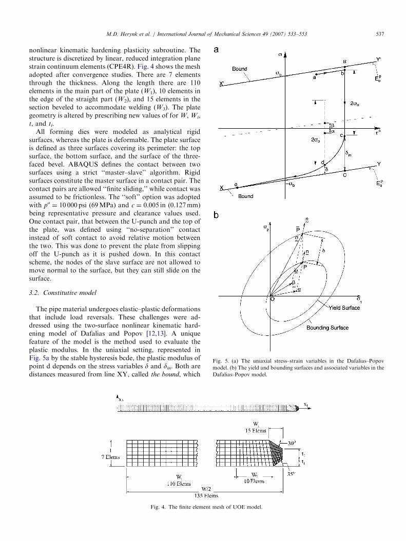
Fig. 5. (a) The uniaxial stress–strain variables in the Dafalias–Popov
model. (b) The yield and bounding surfaces and associated variables in the
Dafalias–Popov model.
M.D. Herynk et al. / International Journal of Mechanical Sciences 49 (2007) 533–553 537
nonlinear kinematic hardening plasticity subroutine. Thestructure is discretized by linear, reduced integration planestrain continuum elements (CPE4R). Fig. 4 shows the meshadopted after convergence studies. There are 7 elementsthrough the thickness. Along the length there are 110elements in the main part of the plate (W1), 10 elements inthe edge of the straight part (W2), and 15 elements in thesection beveled to accommodate welding (W3). The plategeometry is altered by prescribing new values of for W, Wi,t, and ti.
All forming dies were modeled as analytical rigidsurfaces, whereas the plate is deformable. The plate surfaceis defined as three surfaces covering its perimeter: the topsurface, the bottom surface, and the surface of the three-faced bevel. ABAQUS defines the contact between twosurfaces using a strict ‘‘master–slave’’ algorithm. Rigidsurfaces constitute the master surface in a contact pair. Thecontact pairs are allowed ‘‘finite sliding,’’ while contact wasassumed to be frictionless. The ‘‘soft’’ option was adoptedwith po
¼ 10 000 psi (69MPa) and c ¼ 0.005 in (0.127mm)being representative pressure and clearance values used.One contact pair, that between the U-punch and the top ofthe plate, was defined using ‘‘no-separation’’ contactinstead of soft contact to avoid relative motion betweenthe two. This was done to prevent the plate from slippingoff the U-punch as it is pushed down. In this contactscheme, the nodes of the slave surface are not allowed tomove normal to the surface, but they can still slide on thesurface.
3.2. Constitutive model
The pipe material undergoes elastic–plastic deformationsthat include load reversals. These challenges were ad-dressed using the two-surface nonlinear kinematic hard-ening model of Dafalias and Popov [12,13]. A uniquefeature of the model is the method used to evaluate theplastic modulus. In the uniaxial setting, represented inFig. 5a by the stable hysteresis bcde, the plastic modulus ofpoint d depends on the stress variables d and din. Both aredistances measured from line XY, called the bound, which
Fig. 4. The finite element mesh of UOE model.

ARTICLE IN PRESS
-80
-40
0
40
80
0 2 4 6 8
-400
-200
0
200
400
(ksi)
ε (%)
Measured
Fit(MPa)
σ σ
Fig. 6. Uniaxial plate stress–strain response and the Dafalias–Popov fit
used in the simulation.
M.D. Herynk et al. / International Journal of Mechanical Sciences 49 (2007) 533–553538
is the tangent to the stress-plastic strain response at a largevalue of strain (point e in this case). Thus, d is the distanceof point d from the bound and din is the distance of the lastelastic state, point c, from the same line. The plasticmodulus H is related to these variables as follows:
Hðd; dinÞ ¼ Epo þ h
ddin � d
� �, (1)
where Epo is the modulus of the bound and h is a calibration
constant which, in the simplest case, is evaluated through aone-point fit of an experimental stress–strain response.A second bounding line X0Y0 is drawn parallel to XY asshown in the figure.
In the multiaxial setting the YS bc is represented asfollows:
f ðr� aÞ ¼3
2ðs� aÞ � ðs� aÞ
� �1=2¼ so, (2)
where r is the stress tensor and a is the center of the yieldsurface in stress space; s and a are the respective deviatorictensors and so is the size of the yield surface assumed toremain constant. B0C becomes a bounding surface (BS) thatencloses the YS, and is defined by
F ðr� bÞ ¼3
2ðs� bÞ � ðs� bÞ
� �1=2¼ sb. (3a)
Here, sb is the size of the BS, r is the congruent point onthe BS to r on the YS, b is the center of the BS, and s and bare, respectively, their deviators. The two surfaces aregeometrically similar, and as a result, points P and P arecongruent when they have the same normals, as shown inFig. 5b. Thus, the two points are related through
ðr� bÞ ¼sb
so
ðr� aÞ. (3b)
The scalar d is generalized as follows (see Fig. 5b):
d ¼ ðr� rÞ � ðr� rÞ½ �1=2. (4)
Evolution of the yield surface and bounding surface: The YStranslates in stress space according to a chosen hardeningrule that in general is defined by
da ¼ dmm; m � m ¼ 1. (5)
The amount of translation dm is chosen so that theconsistency condition is satisfied. The YS translates alongthe direction PP in Fig. 5b given by
nij ¼ðsij � sijÞ
jsij � sijj. (6)
Here r is the image of r on the outer surface [14]. The ruleensures that the two surfaces come into contact tangen-tially.
The translation of the BS is coupled to that of the YS asfollows:
dbij ¼ daij � dMmij, (7a)
where
mij ¼ðsij � sijÞ
jsij � sijj, (7b)
and
dM ¼ 1�Ep
o
H
� �dsijnij
mklnkl
� �. (7c)
n in Eq. (7c) is the unit normal to the YS at the currentstress point. When the two surfaces come into contact, theBS becomes the active surface and the YS moves so as toremain tangential to it.The model was calibrated on a uniaxial stress–strain
response obtained from a nominal X-70 plate materialshown in Fig. 6. The response includes loading to about7.6% strain, followed by unloading and reverse loading.The response exhibits Luders banding behavior thatextends to about 4.7%. Subsequently the material hardensand deforms uniformly. Reverse loading exhibits theBauschinger effect.The monotonic and hysteresis responses are modeled
independently. The model parameters for each are given inTable 1. For numerical expediency, the Luders banding isavoided by assigning a small positive constant slope to themonotonic part of the response. The fits of the two partsare drawn in Fig. 6 with a dashed line.
3.3. Collapse under external pressure
Once the forming is completed, the pipe is loaded byexternal pressure up to collapse. The pressurization isachieved by surrounding the pipe (one half of the crosssection) with a fluid-filled cavity made of two-nodedhydrostatic fluid elements (F2D2). Fluid is pumped intothe cavity by using the cavity reference node as an inlet.This volume-controlled loading enables the tracing of thepressure maximum that corresponds to the collapsepressure (PCO).
ARTICLE IN PRESS
Table 1
Constitutive model parameters for base case
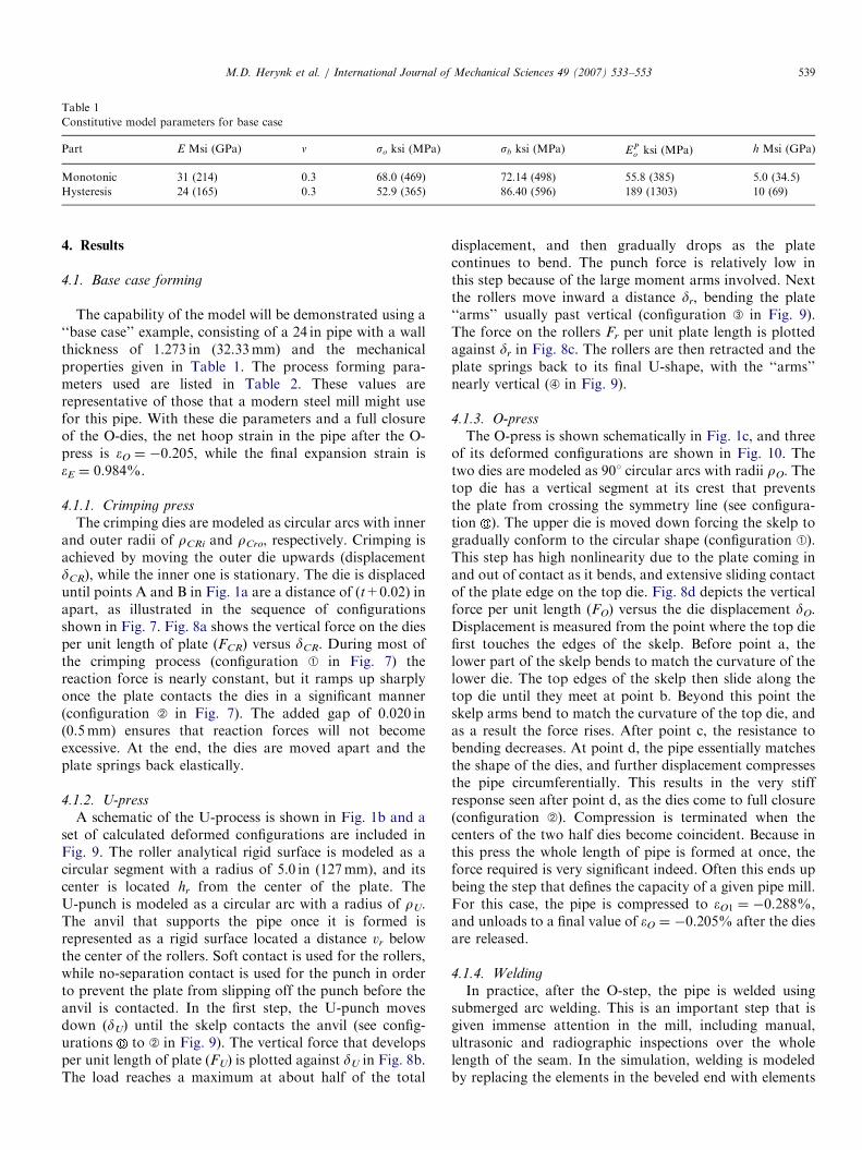
Part E Msi (GPa) n so ksi (MPa) sb ksi (MPa) EPo ksi (MPa) h Msi (GPa)
Monotonic 31 (214) 0.3 68.0 (469) 72.14 (498) 55.8 (385) 5.0 (34.5)
Hysteresis 24 (165) 0.3 52.9 (365) 86.40 (596) 189 (1303) 10 (69)
M.D. Herynk et al. / International Journal of Mechanical Sciences 49 (2007) 533–553 539
4. Results
4.1. Base case forming
The capability of the model will be demonstrated using a‘‘base case’’ example, consisting of a 24 in pipe with a wallthickness of 1.273 in (32.33mm) and the mechanicalproperties given in Table 1. The process forming para-meters used are listed in Table 2. These values arerepresentative of those that a modern steel mill might usefor this pipe. With these die parameters and a full closureof the O-dies, the net hoop strain in the pipe after the O-press is eO ¼ �0.205, while the final expansion strain iseE ¼ 0.984%.
4.1.1. Crimping press
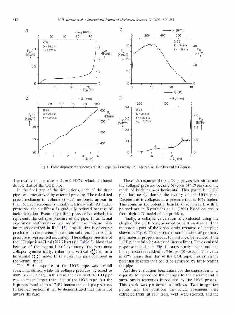
The crimping dies are modeled as circular arcs with innerand outer radii of rCRi and rCro, respectively. Crimping isachieved by moving the outer die upwards (displacementdCR), while the inner one is stationary. The die is displaceduntil points A and B in Fig. 1a are a distance of (t+0.02) inapart, as illustrated in the sequence of configurationsshown in Fig. 7. Fig. 8a shows the vertical force on the diesper unit length of plate (FCR) versus dCR. During most ofthe crimping process (configuration A in Fig. 7) thereaction force is nearly constant, but it ramps up sharplyonce the plate contacts the dies in a significant manner(configuration B in Fig. 7). The added gap of 0.020 in(0.5mm) ensures that reaction forces will not becomeexcessive. At the end, the dies are moved apart and theplate springs back elastically.
4.1.2. U-press
A schematic of the U-process is shown in Fig. 1b and aset of calculated deformed configurations are included inFig. 9. The roller analytical rigid surface is modeled as acircular segment with a radius of 5.0 in (127mm), and itscenter is located hr from the center of the plate. TheU-punch is modeled as a circular arc with a radius of rU.The anvil that supports the pipe once it is formed isrepresented as a rigid surface located a distance vr belowthe center of the rollers. Soft contact is used for the rollers,while no-separation contact is used for the punch in orderto prevent the plate from slipping off the punch before theanvil is contacted. In the first step, the U-punch movesdown (dU) until the skelp contacts the anvil (see config-urations to B in Fig. 9). The vertical force that developsper unit length of plate (FU) is plotted against dU in Fig. 8b.The load reaches a maximum at about half of the total
displacement, and then gradually drops as the platecontinues to bend. The punch force is relatively low inthis step because of the large moment arms involved. Nextthe rollers move inward a distance dr, bending the plate‘‘arms’’ usually past vertical (configuration C in Fig. 9).The force on the rollers Fr per unit plate length is plottedagainst dr in Fig. 8c. The rollers are then retracted and theplate springs back to its final U-shape, with the ‘‘arms’’nearly vertical (D in Fig. 9).
4.1.3. O-press
The O-press is shown schematically in Fig. 1c, and threeof its deformed configurations are shown in Fig. 10. Thetwo dies are modeled as 901 circular arcs with radii rO. Thetop die has a vertical segment at its crest that preventsthe plate from crossing the symmetry line (see configura-tion ). The upper die is moved down forcing the skelp togradually conform to the circular shape (configuration A).This step has high nonlinearity due to the plate coming inand out of contact as it bends, and extensive sliding contactof the plate edge on the top die. Fig. 8d depicts the verticalforce per unit length (FO) versus the die displacement dO.Displacement is measured from the point where the top diefirst touches the edges of the skelp. Before point a, thelower part of the skelp bends to match the curvature of thelower die. The top edges of the skelp then slide along thetop die until they meet at point b. Beyond this point theskelp arms bend to match the curvature of the top die, andas a result the force rises. After point c, the resistance tobending decreases. At point d, the pipe essentially matchesthe shape of the dies, and further displacement compressesthe pipe circumferentially. This results in the very stiffresponse seen after point d, as the dies come to full closure(configuration B). Compression is terminated when thecenters of the two half dies become coincident. Because inthis press the whole length of pipe is formed at once, theforce required is very significant indeed. Often this ends upbeing the step that defines the capacity of a given pipe mill.For this case, the pipe is compressed to eO1 ¼ �0.288%,and unloads to a final value of eO ¼ �0.205% after the diesare released.
4.1.4. Welding
In practice, after the O-step, the pipe is welded usingsubmerged arc welding. This is an important step that isgiven immense attention in the mill, including manual,ultrasonic and radiographic inspections over the wholelength of the seam. In the simulation, welding is modeledby replacing the elements in the beveled end with elements
ARTICLE IN PRESS
Table 2
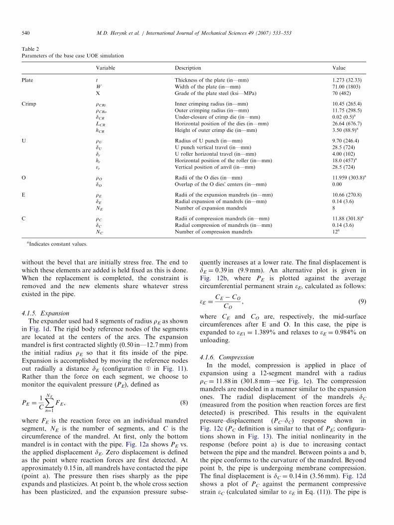
Parameters of the base case UOE simulation
Variable Description Value
Plate t Thickness of the plate (in—mm) 1.273 (32.33)
W Width of the plate (in—mm) 71.00 (1803)
X Grade of the plate steel (ksi—MPa) 70 (482)
Crimp rCRi Inner crimping radius (in—mm) 10.45 (265.4)
rCRo Outer crimping radius (in—mm) 11.75 (298.5)
dCR Under-closure of crimp die (in—mm) 0.02 (0.5)a
LCR Horizontal position of the dies (in—mm) 26.64 (676.7)
hCR Height of outer crimp die (in—mm) 3.50 (88.9)a
U rU Radius of U punch (in—mm) 9.70 (246.4)
dU U punch vertical travel (in—mm) 28.5 (724)
dr U roller horizontal travel (in—mm) 4.00 (102)
hr Horizontal position of the roller (in—mm) 18.0 (457)a
vr Vertical position of anvil (in—mm) 28.5 (724)
O rO Radii of the O dies (in—mm) 11.959 (303.8)a
dO Overlap of the O dies’ centers (in—mm) 0.00
E rE Radii of the expansion mandrels (in—mm) 10.66 (270.8)
dE Radial expansion of mandrels (in—mm) 0.14 (3.6)
NE Number of expansion mandrels 8
C rC Radii of compression mandrels (in—mm) 11.88 (301.8)a
dC Radial compression of mandrels (in—mm) 0.14 (3.6)
NC Number of compression mandrels 12a
aIndicates constant values.
M.D. Herynk et al. / International Journal of Mechanical Sciences 49 (2007) 533–553540
without the bevel that are initially stress free. The end towhich these elements are added is held fixed as this is done.When the replacement is completed, the constraint isremoved and the new elements share whatever stressexisted in the pipe.
4.1.5. Expansion
The expander used had 8 segments of radius rE as shownin Fig. 1d. The rigid body reference nodes of the segmentsare located at the centers of the arcs. The expansionmandrel is first contracted slightly (0.50 in—12.7mm) fromthe initial radius rE so that it fits inside of the pipe.Expansion is accomplished by moving the reference nodesout radially a distance dE (configuration A in Fig. 11).Rather than the force on each segment, we choose tomonitor the equivalent pressure (PE), defined as
PE ¼1
C
XNE
n¼1
F E , (8)
where FE is the reaction force on an individual mandrelsegment, NE is the number of segments, and C is thecircumference of the mandrel. At first, only the bottommandrel is in contact with the pipe. Fig. 12a shows PE vs.the applied displacement dE. Zero displacement is definedas the point where reaction forces are first detected. Atapproximately 0.15 in, all mandrels have contacted the pipe(point a). The pressure then rises sharply as the pipeexpands and plasticizes. At point b, the whole cross sectionhas been plasticized, and the expansion pressure subse-
quently increases at a lower rate. The final displacement isdE ¼ 0.39 in (9.9mm). An alternative plot is given inFig. 12b, where PE is plotted against the averagecircumferential permanent strain eE, calculated as follows:
�E ¼CE � CO
CO
, (9)
where CE and CO are, respectively, the mid-surfacecircumferences after E and O. In this case, the pipe isexpanded to eE1 ¼ 1.389% and relaxes to eE ¼ 0.984% onunloading.
4.1.6. Compression
In the model, compression is applied in place ofexpansion using a 12-segment mandrel with a radiusrC ¼ 11.88 in (301.8mm—see Fig. 1e). The compressionmandrels are modeled in a manner similar to the expansionones. The radial displacement of the mandrels dC
(measured from the position when reaction forces are firstdetected) is prescribed. This results in the equivalentpressure–displacement (PC–dC) response shown inFig. 12c (PC definition is similar to that of PE; configura-tions shown in Fig. 13). The initial nonlinearity in theresponse (before point a) is due to increasing contactbetween the pipe and the mandrel. Between points a and b,the pipe conforms to the curvature of the mandrel. Beyondpoint b, the pipe is undergoing membrane compression.The final displacement is dC ¼ 0.14 in (3.56mm). Fig. 12dshows a plot of PC against the permanent compressivestrain eC (calculated similar to eE in Eq. (11)). The pipe is

ARTICLE IN PRESS
Fig. 7. Three configurations during the crimping process (von Mises stress shown in color contours).
M.D. Herynk et al. / International Journal of Mechanical Sciences 49 (2007) 533–553 541
compressed to a strain of eC1 ¼ �0.390%, and whenunloaded, springs back to eC ¼ �0.171%.
4.2. Base case collapse pressure
The collapse pressure is governed by the circularity ofthe pipe and by the compressive mechanical properties.Fig. 14 shows the shapes of the calculated cross sections ofthe UO (a), UOE (b) and UOC pipes (c) (with the radialdeviation from best-fit circles exaggerated). The shape isaffected by each step of the process. Sector A is influencedmostly by the crimp. Sector B corresponds to the straightarms of the skelp. This section is the last to conform to theO-die, and it remains somewhat flatter than the rest of thecross section. Sector C depends on rU, dr and rO and isseen to be reasonably circular. Initial ovality is theimperfection that mostly influences collapse under externalpressure [2,3]. It is defined as
Do ¼Dmax �Dmin
Dmax þDmin, (10)
where Dmax and Dmin are the maximum and minimumvalues of diameter. For the UO pipe, Do ¼ 0.848% which isa relatively large value.Expanding the UO pipe by eE ¼ 0.984% results in the
shape shown in Fig. 14b. The pipe is now much morecircular, with Do ¼ 0.097%. Sector B is still slightly moredistorted than the rest of the cross section. The expansionhas introduced slight thickness variations in the pipe, assome regions stretched more than others. These are seengreatly distorted in the figure because of the largemagnification of w adopted. Concavities introducedby the eight mandrels can be seen on the inner surface.Fig. 14c shows the profile of the actual UOE pipe beingsimulated. The calculated shape is not exactly the same,primarily because of some differences in the process setting.However the similarity between the two shapes is clearlyvisible.Fig. 14d shows the final shape of the UOC pipe in which
eC ¼ �0.171%. The shape is somewhat less round than theUOE pipe because of the smaller compressive strain used.
ARTICLE IN PRESS
0
0.2
0.4
0 1 2 30
2
4
6
0 20 40 60 80
FCR
(Mlb/ft)
δCR (in)
δCR
(mm)
FCR
(MN/m)
X-70
D = 24.0 in
t = 1.273 in
0
10
20
30
0 10 20 300
20
40
0 200 400 600
δU (mm)
FU
(kips/ft)
δU (in)
FU
(kN/m)
X-70
D = 24.0 in
t = 1.273 in
28
32
36
40
0 1 2 3 4
450
500
550
600
0 20 40 60 80 100
δr (mm)
Fr
(kN/m)Fr
(kips/ft)
δr (in)
X-70
D = 24.0 in
t = 1.273 in
0
0.1
0.2
0.3
0.4
-9 -6 -3 00
1.6
3.2
4.8
-200 -100 0
δO (in)
FO
(Mlb/ft)
δO (mm)
FO
(MN/m)
X-70
D = 24.0 in
t = 1.273 inεO = -0.20%
a b
c d
Fig. 8. Force–displacement responses of UOE steps. (a) Crimping, (b) U-punch, (c) U-rollers and (d) O-press.
M.D. Herynk et al. / International Journal of Mechanical Sciences 49 (2007) 533–553542
The ovality in this case is Do ¼ 0.192%, which is almostdouble that of the UOE pipe.
In the final step of the simulations, each of the threepipes was pressurized by external pressure. The calculatedpressure-change in volume (P�du) responses appear inFig. 15. Each response is initially relatively stiff. At higherpressures, their stiffness is gradually reduced because ofinelastic action. Eventually a limit pressure is reached thatrepresents the collapse pressure of the pipe. In an actualexperiment, deformation localizes after the pressure max-imum as described in Ref. [15]. Localization is of courseprecluded in the present plane strain solution, but the limitpressure is represented accurately. The collapse pressure ofthe UO pipe is 4171 psi (287.7 bar) (see Table 3). Note thatbecause of the assumed half symmetry, the pipe mustcollapse symmetrically, either in a vertical ( ) or in ahorizontal ( ) mode. In this case, the pipe collapsed inthe vertical mode.
The P�du response of the UOE pipe was overallsomewhat stiffer, while the collapse pressure increased to4895 psi (337.6 bar). In this case, the ovality of the UO pipewas so much larger than that of the UOE pipe that theE-process resulted in a 17.4% increase in collapse pressure.In the next section, it will be demonstrated that this is notalways the case.
The P�du response of the UOC pipe was even stiffer andthe collapse pressure became 6843 ksi (471.9 bar) and themode of buckling was horizontal. This particular UOCpipe has nearly double the ovality of the UOE pipe.Despite this it collapses at a pressure that is 40% higher.This confirms the potential benefits of replacing E with Cpointed out in Kyriakides et al. (1991) based on resultsfrom their 1-D model of the problem.Finally, a collapse calculation is conducted using the
shape of the UOE pipe, assumed to be stress-free, and themonotonic part of the stress–strain response of the plateshown in Fig. 6. This particular combination of geometryand material properties can, for instance, be realized if theUOE pipe is fully heat-treated (normalized). The calculatedresponse included in Fig. 15 stays nearly linear until thelimit pressure is reached at 7461 psi (514.6 bar). This valueis 52% higher than that of the UOE pipe, illustrating thepotential benefits that could be achieved by heat-treatingthe pipe.Another evaluation benchmark for the simulation is its
capacity to reproduce the changes to the circumferentialstress–strain responses introduced by the UOE process.This check was performed as follows. Two integrationpoints near the positions the actual specimens wereextracted from (at 1801 from weld) were selected, and the

ARTICLE IN PRESS
Fig. 9. Sequence of configurations during the U-ing process (von Mises stress shown in color contours).
Fig. 10. Initial and two deformed configurations during the O-ing process (color contours show von Mises stress).
M.D. Herynk et al. / International Journal of Mechanical Sciences 49 (2007) 533–553 543

ARTICLE IN PRESS
a
b
0
4
8
0 0.1 0.2 0.3 0.40
320
640
0 4 8
PE
(bar)
PE
(ksi)
δE (in)
δE (mm)
δC (in) εc (%)
δc (mm)
X-70
D = 24.0 in
t = 1.273 in
0
4
8
0 0.4 0.8 1.2 1.60
320
640
εE (%)
Final Strain
εE=0.984%
X-70
D = 24.0 in
t = 1.273 inPE
(ksi)PE
(bar)
b
a
0
2
4
0 0.04 0.08 0.120
160
320
0 1 2 3
PC
(bar)
X-70
D = 24.0 in
t = 1.273 in
0
2
4
0 0.1 0.2 0.3 0.40
160
320
Final Strain
εC=0.171%
X-70
D = 24.0 in
t = 1.273 inPC
(ksi)
PC
(ksi)PC
(bar)
a
c d
b
Fig. 12. (a) Pressure–displacement and (b) pressure–strain responses from simulation of expansion. (c) Pressure–displacement and (d) pressure–strain
responses from simulation of compression.
Fig. 11. Three configurations during the Expansion process (von Mises stress shown in color contour).
M.D. Herynk et al. / International Journal of Mechanical Sciences 49 (2007) 533–553544

ARTICLE IN PRESS
A
B
C
A
B
C
A
B
C
a b
c d
Fig. 14. Pipe cross-sectional shapes from (a) UO simulation, (b) UOE
simulation, (c) actual UOE pipe, (d) UOC simulation.
Fig. 13. Three configurations during the compression process (von Mises stress shown in color contours).
0
2
4
6
8
0 0.1 0.2 0.30
200
400
δυ/υο (%)
(ksi)P
(bar)^
^
X-70
D = 24.0 in
t = 1.273 in
UOE
UOC
UOE-HT
^UO
P
Fig. 15. Calculated pressure-change in volume response of UO, UOE,
UOC and ‘‘heat-treated’’ pipe.
M.D. Herynk et al. / International Journal of Mechanical Sciences 49 (2007) 533–553 545
state variables locked into these points were recorded.Residual stresses were incrementally reduced to zero, andeach point was then loaded to a uniaxial compressionstrain of 1.0% in the circumferential direction. The
predicted stress–strain responses are plotted in Fig. 16.Included are corresponding responses measured experi-mentally. The comparison is quite favorable.
5. Parametric study of UOE/UOC forming
Each step of the UOE process has variables thatinfluence the shape and collapse performance of thefinished pipe. In an effort to quantify the influence of suchparameters on pipe performance, several of these variablesare varied individually, while keeping all other parametersat the values of the base case (Table 2). Unless otherwise

ARTICLE IN PRESS
Table 3
Predicted main pipe shape parameters and collapse pressures
Parameters UO UOE UOC
Circumf. in (mm) 70.855 (1799.7) 71.552 (1817.4) 70.733 (1796.6)
e (%) �0.2048 0.9838 �0.1712
Do (%) 0.848 0.0967 0.192
PCO psi (bar) 4171 (287.7) 4895 (337.6) 6843 (471.9)
Mode
PCO HT psi (bar) — 7461 (514.6) —
0
20
40
60
0 0.2 0.4 0.6 0.8
Experiment
Model
0
200
400
600
σ
(ksi)
ε (%)
Outer
Innerσ
(MPa)
Outer
Inner
1
80
Fig. 16. Comparison of measured and calculated compressive stress–-
strain responses at two locations through the pipe cross section. 4
4.4
4.8
5.2
0
0.5
1
8.5 9 9.5 10 10.5
220 240 260
ρCRi (in)
(%)
PCO
ΔΟ
ρCRi (mm)
PCO(ksi)
U-O
ρCRo = 11.75 in
εO = -0.20 %
4
4.4
4.8
5.2
0
0.5
1
8.5 9 9.5 10 10.5
220 240 260
ρCRi (in)
PCO
ΔΟ
ρCRi (mm)
PCO (ksi)
U-O-E
εE = 1.0 %
ΔΟ
(%)ΔΟ
Fig. 17. Effect of rCRi on the performance of (a) UO and (b) UOE pipes.
M.D. Herynk et al. / International Journal of Mechanical Sciences 49 (2007) 533–553546
stated, the pipe wall thickness is 1.273 in (32.33mm) andthe O- and E-strains are eOE�0.20% and eEE1.00%.Each pipe is collapsed by external pressure after the UOand again after the UOE (or UOC) steps. Each parameteris varied within a range of values that is considered to bepractical. Press load capacities are not considered in thesesimulations.
5.1. Crimping
The main crimp parameters affecting the pipe shape arethe radii of the inner (rCRi) and outer radii (rCRo), and thelength of plate being crimped (LCR). First the radius of theinner crimp die is varied while the radius of the outer die iskept at rCRo ¼ 11.75 in (298.5mm). Fig. 17a shows a plotof the ovality and collapse pressure of UO pipe as afunction of rCRi. The ovality is seen to increase at a lowrate nearly linearly with rCRi, and as a consequence PCO
decreases at a low rate nearly linearly. Thus, a smaller rCRi
produces a rounder pipe. Collapse calculations arerepeated after the pipe is expanded. The ovality andcollapse pressure are plotted against rCRi in Fig. 17b.Expansion removes most of the out-of-roundness and thecollapse pressure increases for all values of rCRi. Somedegradation in collapse pressure remains for rCRi49.75 in(247.6mm).
Next, the inner and outer crimping die radii are variedtogether, with rCRo ¼ (rCRi+1.3) in. This strategy ensuresthat the crimped section has nearly uniform curvature. Thevariable hCR is kept constant for all the cases, while LCR isadjusted so that the plate edge lines up with the corner of

ARTICLE IN PRESSM.D. Herynk et al. / International Journal of Mechanical Sciences 49 (2007) 533–553 547
the outer crimp die. This scheme keeps the length andheight of the crimped zones nearly constant, as the radiiwere varied. Collapse pressures and ovalities are plotted inFig. 18a for UO pipes and in Fig. 18b for UOE pipes. Forboth, the highest collapse pressures correspond to thesmallest set of radii. As the crimp radii are increased, thecollapse pressures drop at first and then steadily rise again.However, overall the collapse pressures are somewhatlower than those in Fig. 17. Again, if the pipe is expandedby 1% the effect of the crimping is essentially erased. WhenLCR was varied, it was found that increasing its value abovethat in Table 2 (26.64 in—676.7mm) produces a modestincrease in the UO collapse pressure, but for LCR428 in(711mm), the collapse pressure begins to reduce. Againwhen the pipes are expanded by 1%, the ovality and PCO
remain nearly constant with LCR.
4
4.4
4.8
5.2
0
0.2
0.4
0.6
0.8
1
8 9 10 11 12 13
220 260 300
ρCRi (in)
PCO
Δο
ρCRi
(mm)
UO
εO = -0.20 %
ρCRo = ρCRi + 1.3 in
A
B
C
4
4.4
4.8
5.2
0
0.2
0.4
0.6
0.8
1
8 9 10 11 12 13
220 260 300
ρCRi (in)
PCO
Δο
ρCRi (mm)
UOE
εE = 1.0 %
(ksi)
(%)
b
a
PCO
(ksi)
PCO
Δο
(%)
Δο
Fig. 18. Effect of rCRo and rCRi on performance of (a) UO and (b) UOE
pipes.
5.2. U-press
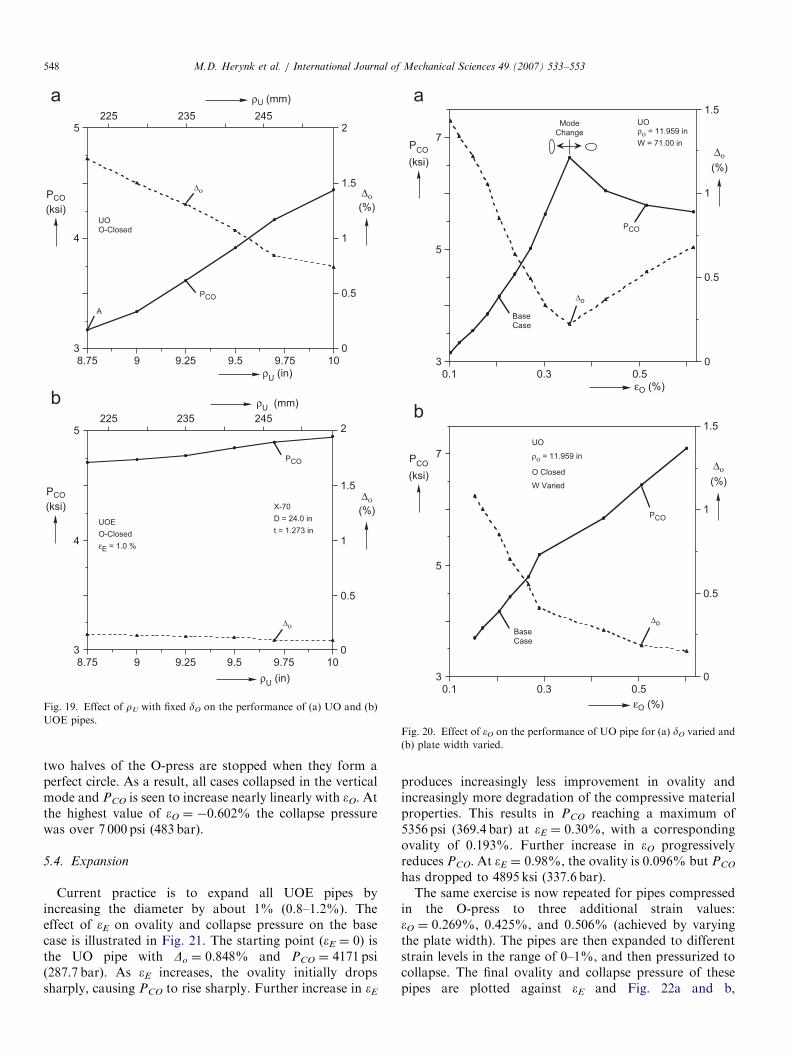
The main parameters of the U-press are the distance ofthe roller center from the plate mid-span (hr), the verticaldisplacement (dU), the horizontal displacement of the siderollers (dr), and the radius of the punch (rU) (Fig. 1b). Eachof these was varied and the effect on the collapse pressureof UO and UOE pipes was evaluated. Of these, the onlyone found to have some effect on PCO is rU. The radius ofthe U-punch is typically selected to result in a radius of thebottom half of the skelp that is near the desired final radiusof the pipe. However, the radius of the skelp must besmaller than the radius of the O-dies for the skelp to fit inthe bottom O-die. rU was varied between 8.75 and 10 in(222–254mm), dr is adjusted to produce vertical skelparms, and all other parameters are kept at the values givenin Table 2. The effects of this on the collapse pressure ofUO and UOE pipes are shown in Fig. 19a and b,respectively. For the UO pipes, PCO and Do vary approxi-mately linearly with rU, and larger punch radii givesignificantly rounder and stronger pipes. However, oncemore, expansion by eEE1% significantly reduces themagnitude of this effect. It was found that the variationin PCO of UO pipe can be eliminated if in each case theO-dies are moved closer together in order to produce aeOE�0.20%. For this to be feasible, the circumference ofeach half die must be somewhat less than prO.Common practice is to select the roller displacement dr
so that the skelp arms end up nearly vertical. In this study,dr was varied so that the angle between the skelp arms andthe vertical varied between �41 and +101 (going below�41 prevents the skelp from fitting inside the top O-die).This has very little affect on the collapse pressure of bothUO and UOE pipes.
5.3. O-press
In the O-press, the U-shaped skelp is first bent into anearly circular shape, and then a net compressive strain eO
is applied. The radius of the dies (rO) is usually fixed by thediameter of the pipe (standard value). eO can be varied byadjusting the displacement of the dies (dO), or the width ofthe plate (W). We first consider varying eO by increasing dO
without concern to die overlap (Fig. 20a) (press loadcapacity is not considered). As eO increases, the collapsepressure goes from just over 3 000 psi (207 bar) ateO ¼ �0.1% to above 6500 psi (448 bar) eO ¼ �0.35%. Itis noted that this increase is partly due to the reduction ofthe ovality in the pipe seen in the figure, but also due to‘‘hardening’’ of the material by compression. For|eO|40.35%, the collapse pressure starts to decreasesomewhat with eO. The peak corresponds to the collapsemode switching from vertical ( ) to horizontal orientation( ). This switch is due to using the closure of the O-diesto vary eO.Fig. 20b shows similar results, in which eO is increased by
increasing the width of the plate (W). In this process the
ARTICLE IN PRESS
3
4
5
0
0.5
1
1.5
2
8.75 9 9.25 9.5 9.75 10
225 235 245
ρU (in)
PCO
Δο
ρU (mm)
UOO-Closed
A
3
4
5
0
0.5
1
1.5
2
8.75 9 9.25 9.5 9.75 10
225 235 245
ρU (in)
PCO
Δο
ρU (mm)
UOE
O-Closed
εE = 1.0 %
X-70
D = 24.0 in
t = 1.273 in
(ksi) (%)
PCO
(ksi)
PCO
Δο
(%)
Δο
Fig. 19. Effect of rU with fixed dO on the performance of (a) UO and (b)
UOE pipes.
3
5
7
0
0.5
1
1.5
0.1 0.3 0.5εO (%)
PCO
Δo
BaseCase
ModeChange
3
5
7
0
0.5
1
1.5
0.1 0.3 0.5
εO (%)
PCO
Δo
UO
ρο = 11.959 in
W Varied
O Closed
BaseCase
ρο = 11.959 in
W = 71.00 in
UO
(ksi)(%)
PCO
(ksi)
PCO
Δο
(%)
Δο
Fig. 20. Effect of eO on the performance of UO pipe for (a) dO varied and
(b) plate width varied.
M.D. Herynk et al. / International Journal of Mechanical Sciences 49 (2007) 533–553548
two halves of the O-press are stopped when they form aperfect circle. As a result, all cases collapsed in the verticalmode and PCO is seen to increase nearly linearly with eO. Atthe highest value of eO ¼ �0.602% the collapse pressurewas over 7 000 psi (483 bar).
5.4. Expansion
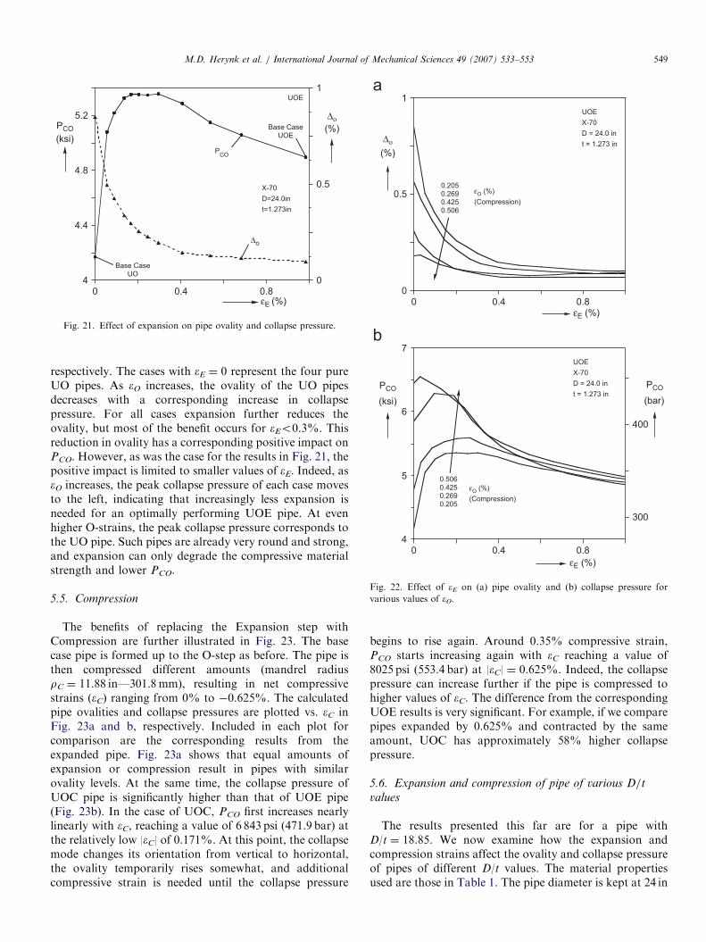
Current practice is to expand all UOE pipes byincreasing the diameter by about 1% (0.8–1.2%). Theeffect of eE on ovality and collapse pressure on the basecase is illustrated in Fig. 21. The starting point (eE ¼ 0) isthe UO pipe with Do ¼ 0.848% and PCO ¼ 4171 psi(287.7 bar). As eE increases, the ovality initially dropssharply, causing PCO to rise sharply. Further increase in eE
produces increasingly less improvement in ovality andincreasingly more degradation of the compressive materialproperties. This results in PCO reaching a maximum of5356 psi (369.4 bar) at eE ¼ 0.30%, with a correspondingovality of 0.193%. Further increase in eO progressivelyreduces PCO. At eE ¼ 0.98%, the ovality is 0.096% but PCO
has dropped to 4895 ksi (337.6 bar).The same exercise is now repeated for pipes compressed
in the O-press to three additional strain values:eO ¼ 0.269%, 0.425%, and 0.506% (achieved by varyingthe plate width). The pipes are then expanded to differentstrain levels in the range of 0–1%, and then pressurized tocollapse. The final ovality and collapse pressure of thesepipes are plotted against eE and Fig. 22a and b,
ARTICLE IN PRESS
4
4.4
4.8
5.2
0
0.5
1
0 0.4 0.8εE (%)
PCO
Δo
UOE
X-70
D=24.0in
t=1.273in
Base CaseUOE
Base CaseUO
(ksi)(%)PCO
Δο
Fig. 21. Effect of expansion on pipe ovality and collapse pressure.
0
0.5
1
0 0.4 0.8εE (%)
εO (%)
(Compression)
0.2050.2690.4250.506
UOE
X-70
D = 24.0 in
t = 1.273 in
4
5
6
7
0 0.4 0.8
300
400
(bar)
εE (%)
εO (%)
(Compression)
0.5060.4250.2690.205
UOE
X-70
D = 24.0 in
t = 1.273 in
(%)
Δο
PCO
(ksi)
PCO
Fig. 22. Effect of eE on (a) pipe ovality and (b) collapse pressure for
various values of eO.
M.D. Herynk et al. / International Journal of Mechanical Sciences 49 (2007) 533–553 549
respectively. The cases with eE ¼ 0 represent the four pureUO pipes. As eO increases, the ovality of the UO pipesdecreases with a corresponding increase in collapsepressure. For all cases expansion further reduces theovality, but most of the benefit occurs for eEo0.3%. Thisreduction in ovality has a corresponding positive impact onPCO. However, as was the case for the results in Fig. 21, thepositive impact is limited to smaller values of eE. Indeed, aseO increases, the peak collapse pressure of each case movesto the left, indicating that increasingly less expansion isneeded for an optimally performing UOE pipe. At evenhigher O-strains, the peak collapse pressure corresponds tothe UO pipe. Such pipes are already very round and strong,and expansion can only degrade the compressive materialstrength and lower PCO.
5.5. Compression
The benefits of replacing the Expansion step withCompression are further illustrated in Fig. 23. The basecase pipe is formed up to the O-step as before. The pipe isthen compressed different amounts (mandrel radiusrC ¼ 11.88 in—301.8mm), resulting in net compressivestrains (eC) ranging from 0% to �0.625%. The calculatedpipe ovalities and collapse pressures are plotted vs. eC inFig. 23a and b, respectively. Included in each plot forcomparison are the corresponding results from theexpanded pipe. Fig. 23a shows that equal amounts ofexpansion or compression result in pipes with similarovality levels. At the same time, the collapse pressure ofUOC pipe is significantly higher than that of UOE pipe(Fig. 23b). In the case of UOC, PCO first increases nearlylinearly with eC, reaching a value of 6 843 psi (471.9 bar) atthe relatively low |eC| of 0.171%. At this point, the collapsemode changes its orientation from vertical to horizontal,the ovality temporarily rises somewhat, and additionalcompressive strain is needed until the collapse pressure
begins to rise again. Around 0.35% compressive strain,PCO starts increasing again with eC reaching a value of8025 psi (553.4 bar) at |eC| ¼ 0.625%. Indeed, the collapsepressure can increase further if the pipe is compressed tohigher values of eC. The difference from the correspondingUOE results is very significant. For example, if we comparepipes expanded by 0.625% and contracted by the sameamount, UOC has approximately 58% higher collapsepressure.
5.6. Expansion and compression of pipe of various D/t
values
The results presented this far are for a pipe withD/t ¼ 18.85. We now examine how the expansion andcompression strains affect the ovality and collapse pressureof pipes of different D/t values. The material propertiesused are those in Table 1. The pipe diameter is kept at 24 in
ARTICLE IN PRESS
0
0.2
0.4
0.6
0.8
1
0 0.4 0.8ε
E/C (%)
UOC
UOE
X-70
D = 24.0 in
t = 1.273 in
4
5
6
7
8
0 0.4 0.8
280
360
440
520
(bar)
εE/C (%)
UOC
UOE
X-70
D = 24.0 in
t = 1.273 inModeChange
Base Case
(%)
PCO
(ksi)
PCO
Δο
Fig. 23. Effect of eE and eC (a) pipe ovality and (b) collapse pressure.
0
0.2
0.4
0.6
0.8
1
1.2
0 0.4 0.8
εE (%)
D
t
X-70
D = 24.0 in
εO = -0.20%
17.4518.8521.3324.0027.43
2
4
6
0 0.4 0.8
160
240
320
400
480
εE (%)
D
t
X-70
D = 24.0 in
εO = -0.20%
17.4518.8521.3324.0027.43
(bar)
(%)
PCO
(ksi)
PCO
Δο
Fig. 24. Effect of eE on (a) pipe ovality and (b) collapse pressure for
various D/t pipes.
M.D. Herynk et al. / International Journal of Mechanical Sciences 49 (2007) 533–553550
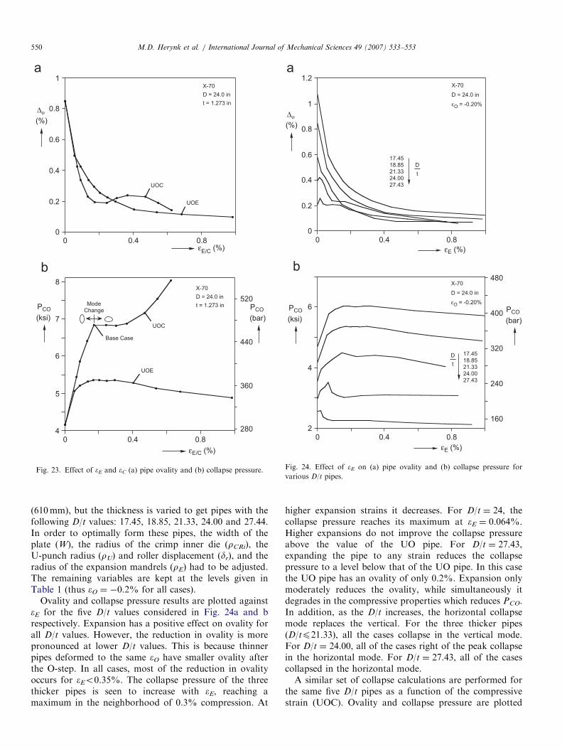
(610mm), but the thickness is varied to get pipes with thefollowing D/t values: 17.45, 18.85, 21.33, 24.00 and 27.44.In order to optimally form these pipes, the width of theplate (W), the radius of the crimp inner die (rCRi), theU-punch radius (rU) and roller displacement (dr), and theradius of the expansion mandrels (rE) had to be adjusted.The remaining variables are kept at the levels given inTable 1 (thus eO ¼ �0.2% for all cases).
Ovality and collapse pressure results are plotted againsteE for the five D/t values considered in Fig. 24a and brespectively. Expansion has a positive effect on ovality forall D/t values. However, the reduction in ovality is morepronounced at lower D/t values. This is because thinnerpipes deformed to the same eO have smaller ovality afterthe O-step. In all cases, most of the reduction in ovalityoccurs for eEo0.35%. The collapse pressure of the threethicker pipes is seen to increase with eE, reaching amaximum in the neighborhood of 0.3% compression. At
higher expansion strains it decreases. For D/t ¼ 24, thecollapse pressure reaches its maximum at eE ¼ 0.064%.Higher expansions do not improve the collapse pressureabove the value of the UO pipe. For D/t ¼ 27.43,expanding the pipe to any strain reduces the collapsepressure to a level below that of the UO pipe. In this casethe UO pipe has an ovality of only 0.2%. Expansion onlymoderately reduces the ovality, while simultaneously itdegrades in the compressive properties which reduces PCO.In addition, as the D/t increases, the horizontal collapsemode replaces the vertical. For the three thicker pipes(D/tp21.33), all the cases collapse in the vertical mode.For D/t ¼ 24.00, all of the cases right of the peak collapsein the horizontal mode. For D/t ¼ 27.43, all of the casescollapsed in the horizontal mode.A similar set of collapse calculations are performed for
the same five D/t pipes as a function of the compressivestrain (UOC). Ovality and collapse pressure are plotted

ARTICLE IN PRESSM.D. Herynk et al. / International Journal of Mechanical Sciences 49 (2007) 533–553 551
against eC in Fig. 25a and b respectively. For the threethicker pipes, finishing the pipe with compression increasesthe collapse pressure significantly. As D/t increases, thebenefit of eC is reduced and essentially disappears for thethinnest pipe considered. The sharp local peaks in Fig. 25bcorrespond to collapse mode changes: cases left of the peakcollapse in the vertical mode, while to the right theycollapse in the horizontal mode. Fig. 25a reveals that thesemode changes correspond to a temporary increase inovality, and the higher the D/t, the larger the increase. Forthinner pipes (D/tX21.33), this increase in ovality ishigh enough to cause PCO to drop and give resultscomparable to the UOE process. As D/t increases, themode change occurs at increasingly lower compressivestrains, until (for D/t ¼ 27.43) all of the cases collapse inthe horizontal mode. For this pipe, compression isdetrimental until relatively high strains (eC40.40%) arereached and the ovality is reduced. This trend for higher
0
0.2
0.4
0.6
0.8
1
1.2
0 0.2 0.4 0.6
εC (%)
εC (%)
X-70
D = 24.0 in
εO = -0.20%
D
t
17.4518.8521.3324.0027.43
2
4
6
8
10
0 0.2 0.4 0.6
200
400
600
D
t
X-70
D = 24.0 in
εO = -0.20%
17.4518.8521.3324.0027.43
b
a
(bar)
(%)
PCO
(ksi)
PCO
Δο
Fig. 25. Effect of eC on (a) pipe ovality and (b) collapse pressure for
various D/t pipes.
D/t pipe is, however, similar to what was observed forexpanded pipe.
5.7. Effect of material yield stress
In order to examine the effect of yield stress on theprocess, the basic stress–strain response used is modified toproduce the two additional curves shown in Fig. 26a.Keeping all other monotonic response fit parameters thesame, the yield stress (som) is assigned the values of 76.0and 61.0 ksi (524 and 490MPa). In addition, the hysteresisyield stress of the two new curves is adjusted so that2soc/som ¼ 1.55.Forming simulations and collapse calculations were
performed using the new stress–strain data together withthe parameters of the base case given in Table 2. Fig. 26bshows the calculated PCO against som for UO, UOE, andUOC pipes. The ovalities are virtually unaffected andtherefore are not included. Over this range of yield stress,PCO varies linearly with som for all three cold-formingprocesses and the slope of each curve is nearly identical.
-100
-50
0
50
100
0 4
-600
0
600
ε (%)
σ(ksi)
σ(MPa)
4
5
6
7
60 64 68 72 76
280
360
440
420 440 460 480 500 520
(ksi)
σom (ksi)
UOE εE = 1.00%
UO εO = -0.20%
UOC εC = -0.24%
D = 24.0 in
t = 1.273 in
σom
(MPa)
2 6 8
a
b
PCO (bar)
PCO
Fig. 26. (a) Three stress–strain responses used in the study. (b) Collapse
pressure vs. plate yield stress.
ARTICLE IN PRESSM.D. Herynk et al. / International Journal of Mechanical Sciences 49 (2007) 533–553552
6. Conclusions
The UOE and UOC pipe manufacturing processes havebeen simulated numerically under plane strain conditions.Following the forming simulation, the pipe was collapsedunder external pressure. The capabilities of the numericalscheme where first demonstrated for an X-70 line-gradesteel pipe with a diameter of 24 in and wall thickness of1.273 in (32.33mm). It was confirmed that the pipe collapsepressure is influenced by its final shape as well as by themechanical properties in compression. It was shown thatthe shape produced by the simulation was quite close tothat of actual pipes. In addition, it was shown that themodel reproduces the degradation in compressive mechan-ical properties seen in the actual pipe. In this case currentlyaccepted values of compressive strain (�0.2%) in theO-press and expansion strain in the expander (1%) wereused. The resulting ovality of UO pipe is relatively high,and thus without the expansion the collapse pressure israther low. Expansion by 1% reduces the ovality butsimultaneously degrades the compressive strength. The netresult is that the collapse pressure increased by 17% overthat of the UO pipe. When the same pipe was finished withcompression, the collapse pressure climbed more than 40%above that of the UOE pipe (depending on the applied eC).The possibility of heat-treating the UOE pipe was alsoinvestigated by adopting its geometry but assigning theproperties of the original plate. In this case the collapsepressure climbed more that 50% above that of the UOEpipe.
In an effort to optimize the forming process for collapseperformance, several of the forming parameters werevaried individually, and their effect on the collapse pressureof UO and UOE pipe was established. The followingconclusions can be drawn from this parametric study.
6.1. Crimping
Crimping affects the shape of the upper part of a UOEpipe. In particular, it affects the shape (and ovality) of UOpipe. It was found that crimp radii (rCRi and rCRo) that aresmaller than the inner and outer radii of the final pipe givehigher UO collapse pressures. Furthermore, reducing thelength of the crimped part tends to increase the UOcollapse pressures. It was also found that if the currentpractice of expanding the diameter of the pipe by about 1%is followed, both the negative and positive effects ofcrimping are usually erased. However, if alternate formingsolutions such as under expansion are adopted, a morecareful selection of the crimping dies can lead to improvedcollapse performance.
6.2. U-ing
Of the four steps, U-ing affects the UO and UOEcollapse pressures the least. The optimal value of rU is theone that produces a pipe radius that closely matches the
O-die radius. Its effect is diminished considerably if eO ofapproximately �0.2% is applied and/or an expansionof 1%.
6.3. O-ing
Compression in the O-step is generally beneficial for thecollapse pressure of both UO and UOE pipe. The mosteffective way of increasing eO is to increase slightly theinitial plate width. For high enough values of eO, thecollapse pressure is high enough to possibly to avoidexpansion altogether (other performance issues not with-standing).
6.4. Expansion
Expansion reduces pipe ovality, but at the same timedegrades the compressive mechanical properties. Forexcessive expansion, this degradation overshadows theimprovement in ovality.The current practice of expanding the pipe by approxi-
mately 1% leads to reduced collapse performance for allcases considered. For all cases, the collapse pressure ismaximized at expansion strains that are smaller than0.35%. This happens despite the fact that underexpandedpipes have slightly higher ovality than fully expandedpipes.For any given UO pipe, an optimum expansion exists
that will balance ovality improvement and materialdegradation effects to maximize PCO. The eE thatmaximizes PCO depends on eO; the bigger eO applied, thesmaller the required eE. At higher values of eO (4|0.5%|)the UO ovality is quite low, and any expansion may causereduction in PCO (see results of recent full scale tests inRef. [16]).Simulations were conducted for pipes with 17.4o
D/to27.5. In all cases the maximum collapse pressureoccurred at values of eE less than about 0.3%. Thestandard practice of expanding to about 1% is too highand detrimental to collapse performance. As D/t increases,the amount of expansion that maximizes PCO decreases.Higher D/t pipes (with eOE�0.2%) may not benefit fromexpansion.High expansion strains tend to reduce the effect
(detrimental or beneficial) on PCO of the parameters ofthe previous forming steps. The collapse pressure dependsmainly on eE, and generally decreases as eE increases.
6.5. Compression
Compressing a UO pipe instead of expanding it reducesthe pipe ovality and increases the pipe’s mechanicalcompressive properties. One way of inducing the requiredcompression is in the O-press. Because the O-press deformsthe whole length of the pipe simultaneously, this is limitedby press capacity and by other factors. A more attractivealternative is to add a new component to the process, which
ARTICLE IN PRESSM.D. Herynk et al. / International Journal of Mechanical Sciences 49 (2007) 533–553 553
will compress the pipe radially in a step-by-step fashion.We envision a segmented female mandrel operating on theouter surface of the pipe (essentially the opposite of thecurrent expansion mandrel) such as the one described inRef. [11]. The beneficial effects of such a device on thecollapse pressure of lower D/t pipes were clearly demon-strated in the simulations. At similar values of strain, UOCyields pipes with similar ovality as UOE but with muchhigher collapse pressures. High enough compression canincrease PCO to values greater than that of the heat-treatedpipe, as the material is hardened past the yield stress of theoriginal plate. For example, for the X-70 pipe withD/t ¼ 18.9 the collapse pressure of UOE with an expansionof 0.98% is 4895 psi (337.6 bar). If this UOE pipe is fullyheat-treated, the collapse pressure can rise to 7461 psi(514.6 bar). The collapse pressure of the UOC pipe is6843 psi (471.9 bar) for a compression of 0.17%, 8025 psi(553.4 bar) for a compression of 0.625% and even highervalues if eC reaches 1%.
It is the firm conclusion of this study that thecommissioning of a compression device would be anenabling technology for deep-water pipeline applications.What is envisioned is that present expanders will continueto be used for land pipelines, where expansion increases thetensile strength in the hoop direction, and for high D/toffshore pipelines. The compression device would be usedfor deep-water pipes, where an increase rather than thecurrent reduction in collapse pressure would result insignificant savings in materials as well as installationcosts. Indeed, for future ultra deep-water applications,the use of the compression device may be the only viablealternative.
Acknowledgments
This work was performed under the JIP StructuralIntegrity of Offshore Pipelines with financial support froma consortium of industrial sponsors. This support isacknowledged with thanks. The finding, opinions, conclu-sions and recommendations expressed herein are those ofthe authors and do not necessarily reflect the views of thesponsors. We wish to also thank Corus Tubes for providingseveral pipe and plate specimens and for technical support.Special thanks go to David Brereton, Mark Fryerand Peter Tait, for their help and advice over a periodof several years on a plethora of details relating to UOEpipe mills.
References
[1] Murphey CE, Langner CG. Ultimate pipe strength under bending,
collapse and fatigue. In: Proceedings of the fourth International
Conference on Offshore Mechanics and Arctic Engineering 1985;1:
467–77.
[2] Yeh M-K, Kyriakides S. On the collapse of inelastic thick-walled
tubes under external pressure. ASME Journal of Energy Resources
Technology 1986;108:35–47.
[3] Yeh M-K, Kyriakides S. Collapse of deepwater pipelines. ASME
Journal of Energy Resources Technology 1988;110:1–11.
[4] Kyriakides S, Corona E, Fischer FJ. On the effect of the UOE
manufacturing process on the collapse pressure of long tubes. In:
Proceedings of the Offshore Technology Conference, OTC6758
1992;4:531–43;
Kyriakides S, Corona E, Fischer FJ. On the effect of the UOE
manufacturing process on the collapse pressure of long tubes. ASME
Journal of Engineering for Industry 1994;116:93–100.
[5] Stark PR, McKeehan DS. Hydrostatic collapse research in support of
the Oman–India gas pipeline. In: Proceedings of the Offshore
Technology Conference, OTC7705 1995;2:105–20.
[6] Al-Sharif AM, Preston R. Improvements in UOE pipe collapse
resistance by thermal aging. In: Proceeding of the Offshore
Technology Conference, OTC8211 1996;2:579–88.
[7] Hall EO. Yieldings of the point phenomena in metals and alloys. New
York: Plenum Press; 1970.
[8] DeGeer D, Marewski U, Hillenbrand H-G, Weber B, Crawford M.
Collapse testing of thermally treated line pipe for ultra-deepwater
applications. In: Proceedings of the 24th International Conference on
Offshore Mechanics and Arctic Engineering, June 20–25, Vancouver,
BC, Canada, Paper OMAE2004-51569, 2004.
[9] DeGeer D, Timms C, Lobanov V. Blue stream collapse test program.
In: International Conference on Offshore Mechanics and Arctic
Engineering, June 12–17, Halkidiki, Greece, Paper OMAE2005-
67260, 2005.
[10] Shinohara Y, Hara T, Tsuru E, Asahi H, Tereda Y, Doi N. Change
of mechanical properties of high strength line pipe by thermal
coating treatment. In: International Conference Offshore Mecha-
nics and Arctic Engineering, June 12–17, Halkidiki, Greece, Paper
OMAE2005-67055, 2005.
[11] Ewart JC. Apparatus for radially compressing articles. US Patent
2,999,405, A.O. Smith Corporation, 1961.
[12] Dafalias YF, Popov EP. A Model of nonlinearly hardening materials
for complex loading. Acta Mechanica 1975;21:173–92.
[13] Dafalias YF, Popov EP. Plastic internal variables formalism of cyclic
plasticity. ASME Journal of Applied Mechanics 1976;43:645–51.
[14] Mroz Z. On the description of anisotropic workhardening. Journal of
Mechanics and Physics of Solids 1967;15:163–75.
[15] Dyau JY, Kyriakides S. On the localization and collapse in
cylindrical shells under external pressure. International Journal of
Solids and Structures 1993;30:463–82.
[16] Fryer M, Tait P, Kyriakides S, Timms C, DeGeer D. The prediction
and enhancement of UOE-DSAW collapse resistance for deepwater
pipelines. In: Proceedings of the fifth biennial International Pipeline
Conference, October 4–8, 2004, Calgary, AL, Canada, vol. 3,
p. 1961–6.