effects of the constraint’s curvature on structural...
TRANSCRIPT

Proc. R. Soc. A (2012) 468, 2191–2209doi:10.1098/rspa.2011.0732
Published online 7 March 2012
Effects of the constraint’s curvature onstructural instability: tensile buckling
and multiple bifurcationsBY D. BIGONI1,*, D. MISSERONI1, G. NOSELLI2 AND D. ZACCARIA3
1Department of Mechanical and Structural Engineering, University of Trento,via Mesiano 77, Trento, Italy
2Department of Engineering, University of Cambridge, Trumpington Street,Cambridge, UK
3Department of Civil and Environmental Engineering, University of Trieste,piazzale Europa 1, Trieste, Italy
Bifurcation of an elastic structure crucially depends on the curvature of the constraintsagainst which the ends of the structure are prescribed to move, an effect that deservesmore attention than it has received so far. In fact, we show theoretically and providedefinitive experimental verification that an appropriate curvature of the constraint overwhich the end of a structure has to slide strongly affects buckling loads and can induce:(i) tensile buckling; (ii) decreasing- (softening), increasing- (hardening) or constant-load(null stiffness) postcritical behaviour; and (iii) multiple bifurcations, determining forinstance two bifurcation loads (one tensile and one compressive) in a single-degree-of-freedom elastic system. We show how to design a constraint profile to obtain adesired postcritical behaviour and we provide the solution for the elastica constrained toslide along a circle on one end, representing the first example of an inflexional elasticadeveloped from a buckling in tension. These results have important practical implicationsin the design of compliant mechanisms and may find applications in devices operating inquasi-static or dynamic conditions, even at the nanoscale.
Keywords: constraint’s curvature; tensile instability; postcritical behaviour; elastica;compliant mechanism
1. Introduction
We begin with a simple example, by considering a one-degree-of-freedom elasticstructure made up of a rigid rod connected with a rotational linear elastic springon its left end and with a roller constrained to move on a circle (of radius Rc,centred on the rod’s axis) on the right (figure 1). The structure is subject to ahorizontal force, so that when this load is compressive and the circle degenerates
*Author for correspondence ([email protected]).
Electronic supplementary material is available at http://dx.doi.org/10.1098/rspa.2011.0732 or viahttp://rspa.royalsocietypublishing.org.
Received 16 December 2011Accepted 8 February 2012 This journal is © 2012 The Royal Society2191
on August 31, 2018http://rspa.royalsocietypublishing.org/Downloaded from

2192 D. Bigoni et al.
= –4l
k
Ft
= 4
= 0
Figure 1. A one-degree-of-freedom structure (with a rotational elastic spring at its left end)evidencing compressive or tensile buckling as a function of the curvature of the constraint (acircular profile with constant curvature, c = ±4) on which the hinge on the right of the structurehas to slide.
to a line (null curvature), the structure buckles at the compressive force,F = −k/l . Our interest is to analyse the case, when the curvature of the constraintis not null, revealing that this curvature strongly affects the critical load, whichresults to be a tensile force1 in the negative curvature case (Ft = k/(3l), forc = l/Rc = −4) and a compressive load for positive curvature (Fc = −k/(5l), forc = l/Rc = 4).
The example shows that the curvature of the constraint at the end of astructure deeply affects its critical load2, but also the shape of the curve definingthe constraint influences the postcritical behaviour, which displays a rising-load (hardening) behaviour in the case of null curvature and a decreasing-load(softening) behaviour for circular profiles (for instance, when c = ±4, as in thestructure shown in figure 1). Moreover, the postcritical behaviour connectedto the tensile (compressive) bifurcation evidences force reversal, because thetensile (compressive) force needed to buckle the structure decreases until itvanishes and becomes compressive (tensile), during continued displacement ofthe structure end.
Once the lesson on the curvature and the shape of the constraint is clear, itbecomes easy to play with these structural elements and discover several neweffects. Some of these are listed as follows.
— A constraint profile can be designed to provide a ‘hardening’, ‘softening’or even a ‘neutral ’ (in which the displacement grows at constant load)postcritical behaviour. More in general, a formula will be given todetermine the shape of the profile to obtain a desired postcriticalbehaviour, including situations in which the stability of the path changesduring postcritical deformation.
1Tensile buckling of an elastic structure, governed by the elastica in which all elements are strictlysubject to tension, has been recently discovered by Zaccaria et al. (2011).2The fact that the curvature influences the critical load was observed in different terms alreadyby Timoshenko & Gere (1961), who analysed the case of the so-called ‘load through a fixed point’.However, they did not generalize the problem enough to discover that: tensile buckling, multiplebifurcations and inflexional tensile elastica during the postcritical behaviour can be obtained, whichis the topic attacked in this study.
Proc. R. Soc. A (2012)
on August 31, 2018http://rspa.royalsocietypublishing.org/Downloaded from
Constraint’s curvature and instability 2193
–2 –1 0 1 2
0
d/Rc
Fl/
k
45
6
shortening, d < 0 lengthening, d > 0
tens
ion
com
pres
sion
RcFd f
f0 = –8° f0 = 8°
f0 = 0°, perfect system
f0 = 0°, perfect system
f0 = –5°
f0 = 5°
l1
2
3
0.20
0.40
–0.20
bifurcation, 0.33
bifurcation, –0.2
k
5 2
3
6 1
4
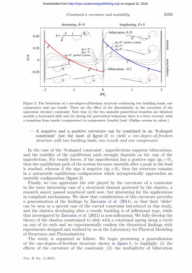
Figure 2. The behaviour of a one-degree-of-freedom structure evidencing two buckling loads, onecompressive and one tensile. These are the effect of the discontinuity in the curvature of the(piecewise circular) constraint. Note that (i) the two unstable postcritical branches are identicalmodulo a horizontal shift and (ii) during the postcritical behaviour there is a force reversal, witha transition from tensile (compressive) to compressive (tensile) load. (Online version in colour.)
— A negative and a positive curvature can be combined in an ‘S-shapedconstraint’ (see the inset of figure 2) to yield a one-degree-of-freedomstructure with two buckling loads: one tensile and one compressive.
In the case of the ‘S-shaped constraint’, imperfections suppress bifurcations,and the stability of the equilibrium path strongly depends on the sign of theimperfection. For tensile forces, if the imperfection has a positive sign (f0 > 0),then the equilibrium path of the system becomes unstable after a peak in the loadis reached, whereas if the sign is negative (f0 < 0), then the structure remainsin a metastable equilibrium configuration which asymptotically approaches anunstable configuration (figure 2).
Finally, we can appreciate the role played by the curvature of a constraintin the more interesting case of a structural element governed by the elastica, aresearch aspect passed unnoticed until now, but interesting for the applicationsin compliant mechanisms. We show that consideration of this curvature providesa generalization of the findings by Zaccaria et al. (2011), so that their ‘slider’can be seen as a special case of the curved constraint introduced in this study,and the elastica developing after a tensile buckling is of inflexional type, whilethat investigated by Zaccaria et al. (2011) is non-inflexional. We fully develop thetheory of the elastica constrained to slide with a rotational spring along a circleon one of its ends and we experimentally confirm the theoretical findings withexperiments designed and realized by us at the Laboratory for Physical Modelingof Structures and Photoelasticity.
The study is organized as follows. We begin presenting a generalizationof the one-degree-of-freedom structure shown in figure 1, to highlight: (i) theeffects of the curvature of the constraint, (ii) the multiplicity of bifurcation
Proc. R. Soc. A (2012)
on August 31, 2018http://rspa.royalsocietypublishing.org/Downloaded from
2194 D. Bigoni et al.
loads, (iii) the behaviour of the imperfect system, and (iv) the possibility ofdesigning a constraint profile to obtain a given postcritical behaviour. Later,we analyse a continuous system, made up of an inextensible beam governed bythe Euler elastica and we solve the critical loads and the nonlinear postcriticallarge-deformation behaviour, through explicit integration of the elastica. Wesystematically complement theoretical results with experiments confirming all ourfindings for discrete and continuous elastic systems. An electronic supplementarymaterial is given, with movie S1 providing a simple illustration of the conceptsexposed in this study, together with a view of experimental results (see alsohttp://ssmg.unitn.it/).
2. Effect of the constraint’s curvature on a one-degree-of-freedom elasticstructure
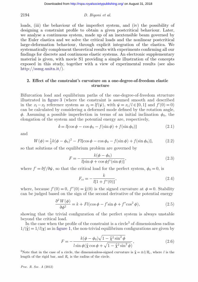
Bifurcation load and equilibrium paths of the one-degree-of-freedom structureillustrated in figure 3 (where the constraint is assumed smooth and describedin the x1−x2 reference system as x2 = lf (j), with j = x1/l ∈ [0, 1] and f ′(0) = 0)can be calculated by considering a deformed mode defined by the rotation angle,f. Assuming a possible imperfection in terms of an initial inclination f0, theelongation of the system and the potential energy are, respectively,
d = l[cos f − cos f0 − f (sin f) + f (sin f0)] (2.1)
and
W (f) = 12k(f − f0)2 − Fl[cos f − cos f0 − f (sin f) + f (sin f0)], (2.2)
so that solutions of the equilibrium problem are governed by
F = − k(f − f0)l[sin f + cos ff ′(sin f)] , (2.3)
where f ′ = vf /vj, so that the critical load for the perfect system, f0 = 0, is
Fcr = − kl[1 + f ′′(0)] , (2.4)
where, because f ′(0) = 0, f ′′(0) = c(0) is the signed curvature at f = 0. Stabilitycan be judged based on the sign of the second derivative of the potential energy
v2W (f)vf2
= k + Fl(cos f − f ′sin f + f ′′cos2 f), (2.5)
showing that the trivial configuration of the perfect system is always unstablebeyond the critical load.
In the case when the profile of the constraint is a circle3 of dimensionless radius1/|c| = 1/l |c| as in figure 1, the non-trivial equilibrium configurations are given by
F = − k(f − f0)√
1 − c2 sin2 f
l sin f(c cos f +√
1 − c2 sin2 f), (2.6)
3Note that in the case of a circle, the dimensionless-signed curvature is c = ±l/Rc, where l is thelength of the rigid bar, and Rc is the radius of the circle.
Proc. R. Soc. A (2012)
on August 31, 2018http://rspa.royalsocietypublishing.org/Downloaded from
Constraint’s curvature and instability 2195
l
x1
x2
x2 = l f (y)
k
d
fFt
Figure 3. A one-degree-of-freedom structure with a hinge constrained to slide along a genericsmooth profile at the right end and a rotational linear-elastic spring at the left end.
and result to be stable when
1 − c2 sin2 f − (f − f0)(cot f − c sin f
√1 − c2 sin2 f) > 0. (2.7)
Equations (2.6) and (2.7) have been used to solve the special case of figure 1(c = ±4), with an ‘S-shaped’ constraint (so that c is discontinuous at f = 0), toobtain the results plotted in figure 2.
(a) The design of the postcritical behaviour
It is important to emphasize that the shape of the profile on which one end of thestructure has to slide can be designed to obtain ‘desired postcritical behaviours’. Letus assume that we want to obtain a certain force–displacement F/d postcriticalbehaviour for the structure sketched in figure 3. Because
d = l[√
1 − j2 − f (j)], (2.8)
to assume a certain F/d relation is equivalent to assume a given dependence ofF on j; therefore, we introduce the dimensionless function
b(j) = lkF(d(j)). (2.9)
Employing equation (2.3), we obtain the condition
f (j) =√
1 − j2 −∫j
0
arcsin g
b(g)√
1 − g2dg, (2.10)
satisfying f (0) = 1 and f ′(0) = 0.Three different profiles designed to obtain particular force F versus rotation
f postcritical behaviours (a sinusoidal, a circular and a constant) are sketchedin figure 4. An interesting case is that of the neutral (or constant) postcriticalbehaviour, in which the rotation f (and therefore also the displacement d) can
Proc. R. Soc. A (2012)
on August 31, 2018http://rspa.royalsocietypublishing.org/Downloaded from

2196 D. Bigoni et al.
Fl /
k
1.00
0.50
0
–0.50
–1.00
1.50
2.00(a) (b)
0.2 0.4 0.6
1.00
0.80
0.60
0.20
0.40
xl /
l
x 2 / l
sinusoidal
constant
circular
fp/2p/4
circular
constant
sinusoidal
0
1.00
0.80
0.60
0.20
0.40
01.00.8
Figure 4. Designed profiles (b) to obtain a given force-rotation postcritical response (a). Thepostcritical responses, given in terms of dimensionless force versus rotation of the structure are:sinusoidal, circular and constant (or ‘neutral’). (Online version in colour.)
grow at constant load4 that can be obtained employing the constraint profileexpressed as
f (j) =√
1 − j2 − 12b
(arcsin j)2, where b = Fcrlk
. (2.11)
(b) Experiments on one-degree-of-freedom elastic systems: multiple buckling andneutral postcritical response
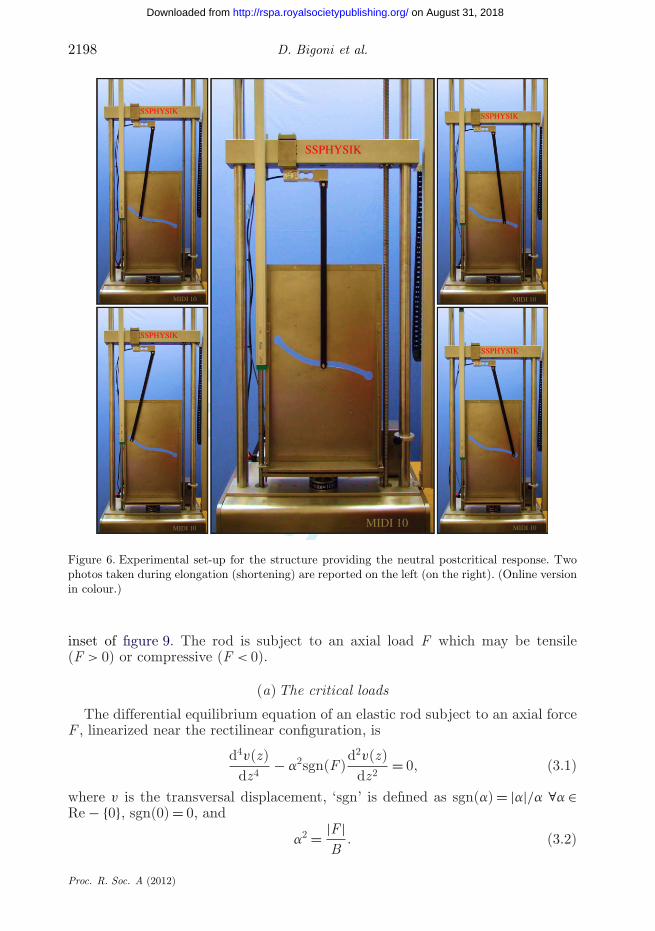
The behaviours obtained employing the simple one-degree-of-freedomstructures are not a mathematical curiosity, but can be realized in practice.In particular, we have realized the ‘S-shaped’ circular constraint shown in theinset of figure 2 and the profile illustrated in figure 4b (labelled ‘constant’),the latter to show a ‘neutral’ or, in other words, ‘constant-force’ response.The experimental apparatuses are shown in figures 5 and 6 (the former relative tothe ‘S-shaped’ semicircular profile; the latter relative to the profile providing theneutral postcritical response), where the grooves have been laser cut (by HTRLaser & Water cut, BZ, Italy) in a 2 mm thick plate of AISI 304 steel and the rollerhas been realized with a (17 mm diameter) steel cylinder mounted with two rollerbearings (SKF-61801-2Z). The rigid bar (600 mm × 50 mm × 20 mm) has beenmachined from an aluminium bar and lightened with longitudinal grooves (seeappendix A), so that its final mass is 820 g. The hinge with rotational spring hasbeen realized with three identical rotational springs, which have been designedusing eqns (32) of Brown (1981) and realized in music wire (4 mm diameter;ASTM A228; see appendix A for further details).
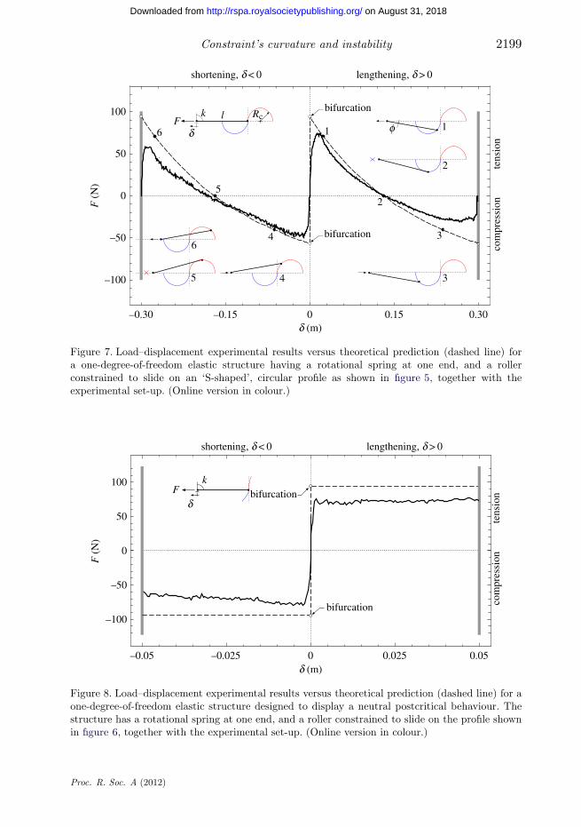
Load–displacement curves are reported in figure 7 for the ‘S-shaped’ circularprofile and in figure 8 for the profile giving the neutral response, as obtained fromexperiments, and directly compared with the theoretical predictions.4A neutral postcritical behaviour has also been found by Gáspár (1984), employing a structuralmodel completely different from that we considered.
Proc. R. Soc. A (2012)
on August 31, 2018http://rspa.royalsocietypublishing.org/Downloaded from
Constraint’s curvature and instability 2197
SSPHYSIK
MIDI 10 MIDI 10
MIDI 10MIDI 10 MIDI 10
SSPHYSIK
SSPHYSIK
SSPHYSIK
SSPHYSIK
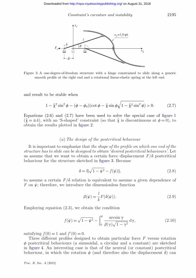
Figure 5. Experimental set-up for the ‘S-shaped’ structure with a groove corresponding to twocircles. Two photos taken during elongation (shortening) are reported on the left (on the right).(Online version in colour.)
We note a good agreement, with buckling detected prior to the attainmentof the theoretical value, in agreement with the known effect of imperfections.Friction at the roller–profile contact has induced some irrelevant load oscillation,minimized by hand-polishing the edges of the groove and using Aero LubricantAS 100 (from Rivolta s.p.a, Milano, Italy). Finally, we may comment that theexperiments confirm the possibility of practically realizing mechanical systemsbehaving as the theoretical modelling predicts.
3. The buckling and postcritical behaviour of an elastic rod with a circularconstraint on one end
We consider an inextensible elastic rod (of bending stiffness B and length l), witha movable clamp at one end, and having a rotational elastic spring (of stiffness k)on the other, which can slide on a circle centred on the axis of the rod, see the
Proc. R. Soc. A (2012)
on August 31, 2018http://rspa.royalsocietypublishing.org/Downloaded from
2198 D. Bigoni et al.
SSPHYSIK
MIDI 10 MIDI 10
MIDI 10MIDI 10 MIDI 10
SSPHYSIK
SSPHYSIK
SSPHYSIK
SSPHYSIK
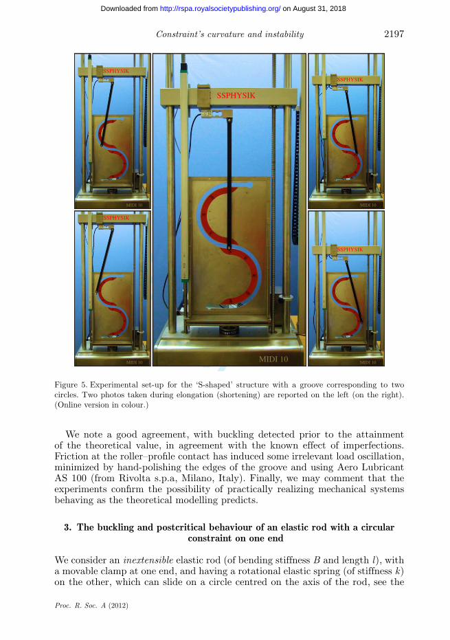
Figure 6. Experimental set-up for the structure providing the neutral postcritical response. Twophotos taken during elongation (shortening) are reported on the left (on the right). (Online versionin colour.)
inset of figure 9. The rod is subject to an axial load F which may be tensile(F > 0) or compressive (F < 0).
(a) The critical loads
The differential equilibrium equation of an elastic rod subject to an axial forceF , linearized near the rectilinear configuration, is
d4v(z)dz4
− a2sgn(F)d2v(z)dz2
= 0, (3.1)
where v is the transversal displacement, ‘sgn’ is defined as sgn(a) = |a|/a ∀a ∈Re − {0}, sgn(0) = 0, and
a2 = |F |B
. (3.2)
Proc. R. Soc. A (2012)
on August 31, 2018http://rspa.royalsocietypublishing.org/Downloaded from
Constraint’s curvature and instability 2199
45
6
1
2
3
52
3
6
–0.30 –0.15 0 0.15 0.30
4
RcFlk
0
100
50
–100
–50
1
bifurcation
bifurcation
d (m)
F (
N)
shortening, d < 0 lengthening, d > 0
fd
tens
ion
com
pres
sion
Figure 7. Load–displacement experimental results versus theoretical prediction (dashed line) fora one-degree-of-freedom elastic structure having a rotational spring at one end, and a rollerconstrained to slide on an ‘S-shaped’, circular profile as shown in figure 5, together with theexperimental set-up. (Online version in colour.)
–0.05 –0.025 0 0.025 0.05
0
100
50
–50
–100bifurcation
bifurcationFk
d (m)
F (
N)
shortening, d < 0 lengthening, d > 0
dte
nsio
nco
mpr
essi
on
Figure 8. Load–displacement experimental results versus theoretical prediction (dashed line) for aone-degree-of-freedom elastic structure designed to display a neutral postcritical behaviour. Thestructure has a rotational spring at one end, and a roller constrained to slide on the profile shownin figure 6, together with the experimental set-up. (Online version in colour.)
Proc. R. Soc. A (2012)
on August 31, 2018http://rspa.royalsocietypublishing.org/Downloaded from

2200 D. Bigoni et al.
The general solution of equation (3.1) is
v(z) = C1
a2cosh(
√sgn(F)az) + C2
a2
√sgn(F) sinh(
√sgn(F)az) + C3z + C4, (3.3)
as well as the boundary conditions (the third involving the rotational springstiffness k) are
v(0) = dv
dz
∣∣∣∣z=0
= 0,
(null displacement and rotation at the clamped end),
−sgn(F)a2
d3v
dz3
∣∣∣∣z=l
= f + dv
dz
∣∣∣∣z=l
,
(shear force on the beam at the rotational spring)
and −Bk
d2v
dz2
∣∣∣∣z=l
= f + dv
dz
∣∣∣∣z=l
,
(moment on the beam at the rotational spring),
⎫⎪⎪⎪⎪⎪⎪⎪⎪⎪⎪⎪⎪⎪⎪⎪⎪⎬⎪⎪⎪⎪⎪⎪⎪⎪⎪⎪⎪⎪⎪⎪⎪⎪⎭
(3.4)
plus the kinematic compatibility condition defining f
f = c
lv(l), (3.5)
involving the signed, dimensionless curvature c = ±l/Rc of the circle.Imposing conditions (3.4)–(3.5), the solution (3.3) provides the condition for
the critical loads(1|c| + sgn(c)
)al sgn(F) cosh(
√sgn(F)al) − sgn(c)
√sgn(F) sinh(
√sgn(F)al)
+ kBa
[(1|c| + sgn(c)
)al
√sgn(F) sinh(
√sgn(F)al)
+ sgn(c)(1 − cosh(√
sgn(F)al))]
= 0, (3.6)
corresponding in the two limits k → 0 and k → ∞ to a pinned and clampedconstraint on the right end, respectively.
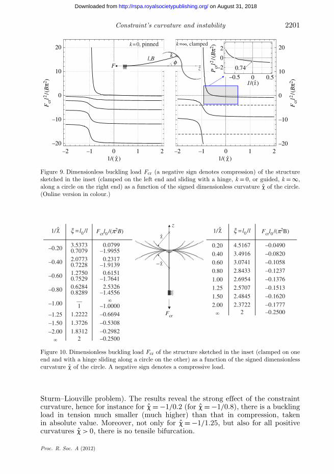
Buckling loads (made dimensionless through multiplication by l2/(p2B)) arereported in figures 9–11, as functions of the signed radius of curvature c of theconstraint.
Results reported in figures 10 and 11 (where the negative signs denotecompressive loads) are given in terms of effective length factor x defined as
Fcr = p2B(xl)2
. (3.7)
We note from figures 9 to 11 that for certain curvatures of the constraint thereis one buckling load in tension, whereas there are always infinite bifurcationsin compression (hence we can comment that the bifurcation problem remains a
Proc. R. Soc. A (2012)
on August 31, 2018http://rspa.royalsocietypublishing.org/Downloaded from
Constraint’s curvature and instability 2201
–2 –1 0 1 2–20
–10
0
10
20
Fcr
l2 / (B
p2 )
Fcr
l2 / (B
p2 )
Pcr
l2 / (B
p2 )
–2 –1 0 1 2–20
–10
0
10
20
l,B
zF
k
k = 0, pinned k = , clamped
0
0–0.5
–2
2
0.74
0.5
1/( ) 1/( )
1/( )
f
∞
Figure 9. Dimensionless buckling load Fcr (a negative sign denotes compression) of the structuresketched in the inset (clamped on the left end and sliding with a hinge, k = 0, or guided, k = ∞,along a circle on the right end) as a function of the signed dimensionless curvature c of the circle.(Online version in colour.)
–0.20 3.5373
–0.40 2.0773
–0.60 1.2750
–0.80 0.8289
–1.00
–1.25 1.2222
–1.50 1.3726
–2.00 1.8312
Fcrl0 /(p2B)
1
0.20 4.5167
0.40 3.4916
0.60 3.0741
0.80 2.8433
1.00 2.6954
1.25 2.5707
1.50 2.4845
2.00 2.3722
Fcr2
z
0.7079
0.7228
0.75290.6284
2
1/
–
x = l0 /l Fcrl0 /(p2B)1/ x = l0 /l
0.0799–1.99550.2317
–1.91390.6151
–1.76412.5326
–1.4556
–1.0000–0.6694–0.5308–0.2982–0.2500
–0.2500–0.1777–0.1620–0.1513–0.1376–0.1237–0.1058–0.0820
–0.0490
—
Figure 10. Dimensionless buckling load Fcr of the structure sketched in the inset (clamped on oneend and with a hinge sliding along a circle on the other) as a function of the signed dimensionlesscurvature c of the circle. A negative sign denotes a compressive load.
Sturm–Liouville problem). The results reveal the strong effect of the constraintcurvature, hence for instance for c = −1/0.2 (for c = −1/0.8), there is a bucklingload in tension much smaller (much higher) than that in compression, takenin absolute value. Moreover, not only for c = −1/1.25, but also for all positivecurvatures c > 0, there is no tensile bifurcation.
Proc. R. Soc. A (2012)
on August 31, 2018http://rspa.royalsocietypublishing.org/Downloaded from

2202 D. Bigoni et al.
–0.20 1.5372
–0.40 2.2588
–0.60 1.7689
–0.80 0.6375
–1.00
–1.25 0.6862
–1.50 0.7742
–2.00 0.8554
0.20 1.2579
0.40 1.2053
0.60 1.1704
0.80 1.1459
1.00 1.1274
1.25 1.1102
1.50 1.0969
2.00 1.07811
– 1
Fcr
z
0.5
0.5
–
Fcrl0 /(p2B)1/ x = l0 /l Fcrl0 /(p2B)1/ x = l0 /l
–1.0000
–1.6682–1.3666
–2.1234
–4.0000
–4.0000
0.5 –4.00002.4608
0.3196
–0.4232
–0.1960
–1.0000–0.8603–0.8312–0.8114–0.7868–0.7616–0.7300–0.6884
–0.6320
—
Figure 11. Dimensionless buckling load Fcr of the structure sketched in the inset (clamped on oneend and guided along a circle on the other end) as a function of the signed dimensionless curvaturec of the circle. A negative sign denotes a compressive load.
(b) The elastica
The shape of the constraint has a strong effect on the postcritical behaviour, aswill be shown below with reference to the case of the circular profile. This effectcan be exploited for the design of compliant mechanisms, hence the solution ofthis problem is not only of academic interest. Therefore, we derive the solutionfor an elastic rod clamped to the left and constrained on the right to slide witha rotational spring (of stiffness kr) on a ‘S-shaped’ bi-circular profile, as sketchedin figure 12, where the local reference system to be used in the analysis is alsoindicated.
The elastic line problem is governed by the following equations.
— A condition of kinematic compatibility can be obtained by observing fromfigure 12 that the coordinates of the elastica evaluated at s = l , namelyx1(l) and x2(l), are related to the angle of rotation of the local referencesystem f and to the radius Rc of the constraint via
[x1(l) ∓ Rc] tan f − x2(l) = 0, (3.8)
where f is assumed positive if anticlockwise; note that in equation (3.8)the sign ‘−’ (‘+’) holds for the case of the rotational spring lying on theleft (right) half-circle.
— The curved constraint transmits to the rod a moment and a force pointingthe centre of the circle, in other words, parallel to x1 and assumed positivewhen opposite to the direction of the x1-axis, so that for 0 ≤ f < p/2 (p/2 <f ≤ p) it corresponds to a positive tensile (negative compressive) dead forceF applied to the structure defined by
F = R cos f. (3.9)
Proc. R. Soc. A (2012)
on August 31, 2018http://rspa.royalsocietypublishing.org/Downloaded from

Constraint’s curvature and instability 2203
l,B
F
d
s Rc
Rcx 2
(l)
x 2
x 1
x 1(l)
q(s)
f
kr
kr
R
M(0)=krq(0)
Figure 12. The elastic line problem for a rod clamped at the left end and constrained to slide witha rotational spring (of stiffness kr) on a circle at the right end. Note the reference system employedin the analysis.
— Through introduction of the curvilinear coordinate s, the fully nonlinearequation of the elastica-governing deflections of the rod is
d2q
ds2− R
Bsin q = 0, (3.10)
where q is the rotation angle (assumed positive if clockwise) of the normalat each point of the elastica, hence with the symbols introduced infigure 12, we find the condition
q(l) = f. (3.11)
Integration of equation (3.10) from 0 to s, after multiplication by dq/ds,leads to (
dq
ds
)2
= 2a2[
2k2
− 1 − sgn(R) cos q
], (3.12)
where
a2 = |R|B
, k2 = 4a2
[q(0)kr/B]2 + 2a2[sgn(R) cos q(0) + 1] , (3.13)
in which the term q(0)kr corresponds to the moment evaluated at s = 0. Theintroduction of the change of variable
b = [q − H(R)p]2
, (3.14)
Proc. R. Soc. A (2012)
on August 31, 2018http://rspa.royalsocietypublishing.org/Downloaded from

2204 D. Bigoni et al.
where H denotes the Heaviside step function, allows to rewrite equation (3.12) as
(db
ds
)2
= a2
k2(1 − k2 sin2 b), (3.15)
so that a second change of variable u = sa/k yields
db
du= ±
√1 − k2 sin2 b. (3.16)
Restricting the treatment to the case ‘+’, which corresponds to q(0) ≥ 0, andas b = b(0) at u = 0, equation (3.16) provides the following solution for b
b = am[u + F[b(0), k], k], (3.17)
where ‘am’ and ‘F’ are the Jacobi elliptic function amplitude and the incompleteelliptic integral of the first kind of modulus k, respectively (Byrd & Friedman1971). Keeping into account that dx1/ds = cos q and dx2/ds = sin q, an integrationprovides the two coordinates x1 and x2 of the elastica expressed in terms of u as
x1 = sgn(R)2ka
{(1 − k2
2
)u + E[b(0), k] − E[am[u + F[b(0), k], k], k]
}
and x2 = sgn(R)2ka
{dn[u + F[b(0), k], k] − dn[F[b(0), k], k]},
⎫⎪⎪⎬⎪⎪⎭
(3.18)
in which the constants of integration are chosen, so that x1 and x2 vanish ats = 0. In equation (3.18), ‘dn’ is the Jacobi elliptic function delta-amplitude ofmodulus k, where ‘E’ is the incomplete elliptic integral of the second kind (Byrd &Friedman 1971). Equation (3.18) generalizes the expressions derived by Zaccariaet al. (2011, their eqns (3.23) and (3.24)), which are recovered when q(0) = 0.
The horizontal displacement d of the clamp on the left of the structure (assumedpositive for a lengthening of the system) is given in the form
d = x2
sin f− l ∓ Rc, (3.19)
where, as for equation (3.8), the sign ‘−’ (‘+’) holds for the case of the rotationalspring lying on the left (right) half-circle.
The axial load F can be obtained as a function of the rotation f, or as afunction of the end displacement d, through the following steps.
(i) A value for q(0) is fixed, hence k can be expressed using equation (3.13)as a function of R;
(ii) the expressions (3.18) for the coordinates of the elastica andequation (3.17), evaluated at s = l , become functions of R only;
(iii) equation (3.11) provides f, so that equation (3.8) becomes a nonlinearequation in the variable R, which can be numerically solved (we have usedthe function FINDROOT of MATHEMATICA 6.0); and
(iv) once R is known, F , f and d can be, respectively, obtained fromequations (3.9), (3.11) and (3.19).
Proc. R. Soc. A (2012)
on August 31, 2018http://rspa.royalsocietypublishing.org/Downloaded from
Constraint’s curvature and instability 2205
–2 –1 0 1 2
–0.10
–0.05
0
0.05
0.101
2
34
5
61
2
345
6
0.15
bifurcation
bifurcation
RcFl,B
shortening, d < 0 lengthening, d < 0
d
tens
ion
com
pres
sion
d /Rc
Fl2 / (
Bp2 )
Figure 13. The postcritical behaviour of the structure sketched in the inset (with a roller slidingon the ‘S-shaped’ profile) corresponding to the first mode under tensile and compressive loads.Dimensionless axial load F versus dimensionless end displacement. (Online version in colour.)
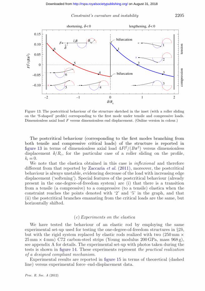
The postcritical behaviour (corresponding to the first modes branching fromboth tensile and compressive critical loads) of the structure is reported infigure 13 in terms of dimensionless axial load 4Fl2/(Bp2) versus dimensionlessdisplacement d/Rc, for the particular case of a roller sliding on the profile,kr = 0.
We note that the elastica obtained in this case is inflexional and thereforedifferent from that reported by Zaccaria et al. (2011), moreover, the postcriticalbehaviour is always unstable, evidencing decrease of the load with increasing edgedisplacement (‘softening’). Special features of the postcritical behaviour (alreadypresent in the one-degree-of-freedom system) are (i) that there is a transitionfrom a tensile (a compressive) to a compressive (to a tensile) elastica when theconstraint reaches the points denoted with ‘2’ and ‘5’ in the graph, and that(ii) the postcritical branches emanating from the critical loads are the same, buthorizontally shifted.
(c) Experiments on the elastica
We have tested the behaviour of an elastic rod by employing the sameexperimental set-up used for testing the one-degree-of-freedom structures in §2b,but with the rigid system replaced by elastic rods realized with two (250 mm ×25 mm × 4 mm) C72 carbon-steel strips (Young modulus 200 GPa, mass 968 g),see appendix A for details. The experimental set-up with photos taken during thetests is shown in figure 14. These experiments represent the practical realizationof a designed compliant mechanism.
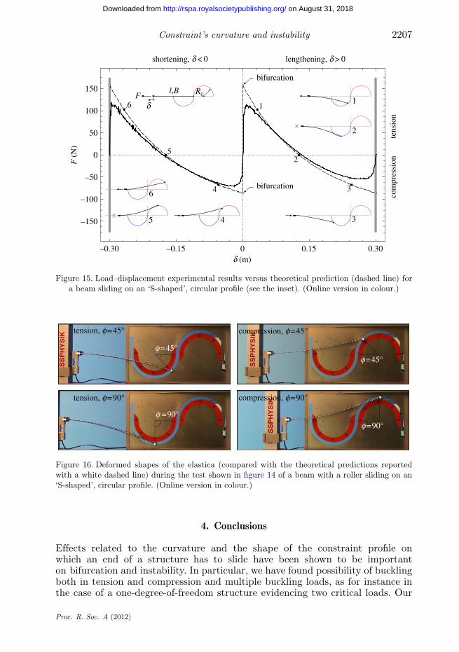
Experimental results are reported in figure 15 in terms of theoretical (dashedline) versus experimental force–end-displacement data.
Proc. R. Soc. A (2012)
on August 31, 2018http://rspa.royalsocietypublishing.org/Downloaded from

2206 D. Bigoni et al.
SSPHYSIK
MIDI 10 MIDI 10
MIDI 10MIDI 10 MIDI 10
SSPHYSIK
SSPHYSIK
SSPHYSIK
SSPHYSIK
(a)
(b) (e)
(c) (d)
Figure 14. Deformed shapes of the elastica during a test of a beam sliding on an ‘S-shaped’, circularprofile. Two photos taken during elongation (shortening) are reported on the left (on the right).Note that the system represents a compliant mechanism of designed response. (Online version incolour.)
Moreover, the photos reported in figure 16, which are details of the photosshown in figure 14a,b,d,e are compared with the theoretical shape of the elastica(shown with a white dashed line and obtained from equation (3.18)) at twodifferent end angles (45◦ and 90◦ for tension and compression).
From the figures, we can observe the following facts.
— The experiments definitely substantiate theoretical findings.— The comparison between the deformed beam during a test and the
predictions of the elastica, shown in figure 16, reveals a very tightagreement between theory and experiments.
As for the one-degree-of-freedom systems, we can again conclude that theexperiments confirm the possibility of practically realizing elastic systemsbehaving in strict agreement with theoretical predictions.
Proc. R. Soc. A (2012)
on August 31, 2018http://rspa.royalsocietypublishing.org/Downloaded from
Constraint’s curvature and instability 2207
–0.30 –0.15 0 0.15 0.30
0 2
34
1
2
345
6
6
bifurcation
bifurcation
150
100
50
–50
–100
–150
5
1
RcFl,B
d (m)
F (
N)
shortening, d < 0 lengthening, d > 0
d
tens
ion
com
pres
sion
Figure 15. Load–displacement experimental results versus theoretical prediction (dashed line) fora beam sliding on an ‘S-shaped’, circular profile (see the inset). (Online version in colour.)
tension, f=90°
tension, f=45°
f=45°
f =90°
f=45°
f=90°
compression, f=45°
compression, f=90°
Figure 16. Deformed shapes of the elastica (compared with the theoretical predictions reportedwith a white dashed line) during the test shown in figure 14 of a beam with a roller sliding on an‘S-shaped’, circular profile. (Online version in colour.)
4. Conclusions
Effects related to the curvature and the shape of the constraint profile onwhich an end of a structure has to slide have been shown to be importanton bifurcation and instability. In particular, we have found possibility of bucklingboth in tension and compression and multiple buckling loads, as for instance inthe case of a one-degree-of-freedom structure evidencing two critical loads. Our
Proc. R. Soc. A (2012)
on August 31, 2018http://rspa.royalsocietypublishing.org/Downloaded from
2208 D. Bigoni et al.
load frame
accelerometer
displacement transducer
stiffeners
load cell
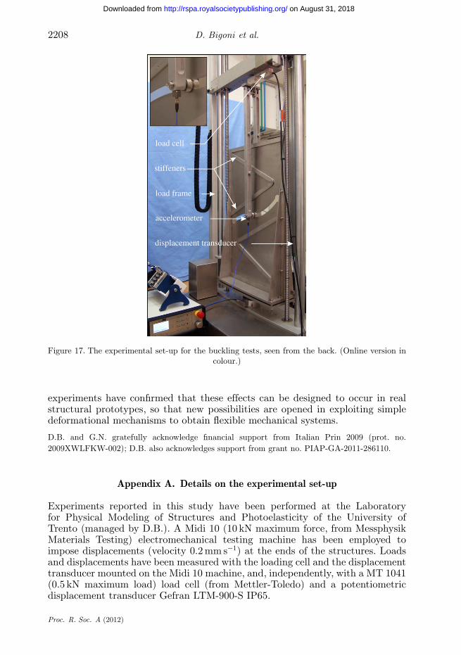
Figure 17. The experimental set-up for the buckling tests, seen from the back. (Online version incolour.)
experiments have confirmed that these effects can be designed to occur in realstructural prototypes, so that new possibilities are opened in exploiting simpledeformational mechanisms to obtain flexible mechanical systems.
D.B. and G.N. gratefully acknowledge financial support from Italian Prin 2009 (prot. no.2009XWLFKW-002); D.B. also acknowledges support from grant no. PIAP-GA-2011-286110.
Appendix A. Details on the experimental set-up
Experiments reported in this study have been performed at the Laboratoryfor Physical Modeling of Structures and Photoelasticity of the University ofTrento (managed by D.B.). A Midi 10 (10 kN maximum force, from MessphysikMaterials Testing) electromechanical testing machine has been employed toimpose displacements (velocity 0.2 mm s−1) at the ends of the structures. Loadsand displacements have been measured with the loading cell and the displacementtransducer mounted on the Midi 10 machine, and, independently, with a MT 1041(0.5 kN maximum load) load cell (from Mettler-Toledo) and a potentiometricdisplacement transducer Gefran LTM-900-S IP65.
Proc. R. Soc. A (2012)
on August 31, 2018http://rspa.royalsocietypublishing.org/Downloaded from

Constraint’s curvature and instability 2209
The rotational springs employed for the one-degree-of-freedom systems havebeen designed to provide a stiffness equal to 211.5 Nm by employing eqns (32)of Brown (1981). After machining, the springs have been tested and found tocorrespond to a stiffness equal to 169.5 Nm, the value which has been used tocompare experiments with theoretical results.
An IEPE accelerometer (PCB Piezotronics Inc., model 333B50) has beenattached at one end of the structure to precisely detect the instant of buckling.This has been observed in all tests to correspond to an acceleration peak rangingbetween 0.15 and 0.2 g, while before buckling and during postcritical behaviourthe acceleration did not exceed the value 0.003 g.
Data from the load cell MT 1041, the displacement transducer Gefran LTM-900-S IP65, and the accelerometer PCB 333B50 have been acquired with a systemNI CompactDAQ, interfaced with LABVIEW 8.5.1 (National Instruments), whereasacquisition of the data from the Midi 10 has been obtained from a Doli EDC 222controller.
Temperature near the testing machine has been monitored with a thermocoupleconnected to a Xplorer GLX Pasco and has been found to lie around 22◦C,without sensible oscillations during tests.
Photos have been taken with a Nikon D200 digital camera, equipped withAF Nikkor (18–35 mm 1 : 3.5–4.5 D) lens (Nikon Corporation) and movies havebeen recorded during the tests with a Sony handycam (model HDR-XR550VE).The testing set-up is shown in figure 17. Additional material can be found athttp://ssmg.unitn.it/.
References
Brown, A. A. D. 1981 Mechanical springs. Oxford, UK: Oxford University Press.Byrd, P. F. & Friedman, M. D. 1971 Handbook of elliptic integrals for engineers and scientists. New
York, NY: Springer-Verlag.Gáspár, Z. 1984 Buckling model for a degenerated case. Newsl. Tech. Univ. Budapest 4, 5–8.Timoshenko, S. P. & Gere, J. M. 1961 Theory of elastic stability. New York, NY: McGraw-Hill.Zaccaria, D., Bigoni, D., Noselli, G. & Misseroni, D. 2011 Structures buckling under tensile dead
load. Proc. R. Soc. A 467, 1686–1700. (doi:10.1098/rspa.2010.0505)
Proc. R. Soc. A (2012)
on August 31, 2018http://rspa.royalsocietypublishing.org/Downloaded from