effects of lumbar arthrodesis on the adjacent segments
TRANSCRIPT

Effects of lumbar arthrodesis on the adjacent segments
- Analysis by finite element model
Taeyup Kim
Department of Medicine
The Graduate School, Yonsei University

Effects of lumbar arthrodesis on the adjacent segments
- Analysis by finite element model
Directed by Professor Yoon Ha
The Master's Thesis submitted to the Department of Medicine the Graduate School of Yonsei University
in partial fulfillment of the requirements for the degree of Master of Medical Science
Taeyup Kim
June 2011

This certifies that the Master's Thesis of Taeyup Kim is approved.
Thesis Supervisor : Yoon Ha
Thesis Committee Member#1 : Keungnyun Kim
Thesis Committee Member#2 : Hye Yeon Lee
The Graduate School Yonsei University
June 2011

ACKNOWLEDGEMENTS
First of all, I appreciate Professor Yoon Ha, Professor Keung Nyun Kim, and Professor Hye Yeon Lee for leading and helping me to complete this thesis. Without the help of the three Professors on every step in writing this thesis, I could not finish. Also, I thank Professor Do Heum Yoon and all other staff members of neurosurgery department for teaching me to be a neurosurgeon. I will always try to keep in my mind all I have learned. Finally, I would like to express my gratitude to Kyung Tak Kang for simulation and computing the finite element model.
<TABLE OF CONTENTS> ABSTRACT ······································································ 1
I. INTRODUCTION ····························································· 3 II. MATERIALS AND METHODS ············································ 4 1. Finite element model ······················································ 4
2. Material properties ························································· 5 3. Arthrodesis models ························································ 6
A. Anterior lumbar interbody fusion model ···························· 7 B. Posterior lumbar interbody fusion model ··························· 7 C. Semi-rigid fixation model ············································· 7 D. Rigid fixation model ··················································· 7
4. Boundary and loading conditions ········································ 8 III. RESULTS ··································································· 9 1. Model validations ························································ 9 2. Changes of disc pressure in the arthrodesis models ·················· 9 3. Changes of contact force in the arthrodeis models ················· 10 IV. DISCUSSION ······························································ 12 V. CONCLUSION ····························································· 13 REFERENCES ································································· 14 ABSTRACT (IN KOREAN) ················································· 17
LIST OF FIGURES
Figure 1. Illustration of the four arthrodesis models ·············· 6 Figure 2. The comparison between the current intact model and a
previous study ·············································· 9 Figure 3. Disc pressure increase of arthrodesis models compared
with intact model ·········································· 10 Figure 4. Contact force increase of arthrodesis models compared
with intact model ·········································· 11
LIST OF TABLES
Table 1. Material properties used in the FE model ················ 5
1
ABSTRACT
Effects of lumbar arthrodesis on the adjacent segments - Analysis by FE model
Taeyup Kim
Department of Medicine
The Graduate School, Yonsei University
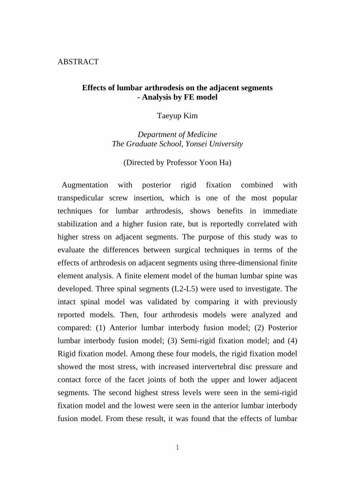
(Directed by Professor Yoon Ha) Augmentation with posterior rigid fixation combined with
transpedicular screw insertion, which is one of the most popular techniques for lumbar arthrodesis, shows benefits in immediate stabilization and a higher fusion rate, but is reportedly correlated with higher stress on adjacent segments. The purpose of this study was to evaluate the differences between surgical techniques in terms of the effects of arthrodesis on adjacent segments using three-dimensional finite element analysis. A finite element model of the human lumbar spine was developed. Three spinal segments (L2-L5) were used to investigate. The intact spinal model was validated by comparing it with previously reported models. Then, four arthrodesis models were analyzed and compared: (1) Anterior lumbar interbody fusion model; (2) Posterior lumbar interbody fusion model; (3) Semi-rigid fixation model; and (4) Rigid fixation model. Among these four models, the rigid fixation model showed the most stress, with increased intervertebral disc pressure and contact force of the facet joints of both the upper and lower adjacent segments. The second highest stress levels were seen in the semi-rigid fixation model and the lowest were seen in the anterior lumbar interbody fusion model. From these result, it was found that the effects of lumbar

2
arthrodesis on adjacent segments could vary according to the surgical technique used for arthrodesis. Semi-rigid fixation deserves careful consideration and further detailed study because it may cause less stress on the adjacent segments than rigid fixation, while maintaining the benefits of the latter procedure.
Key words: lumbar spine, adjacent segment, arthrodesis, dynamic
stabilization, semirigid fixation, finite element analysis

3
Effects of lumbar arthrodesis on the adjacent segments
- Analysis by FE model
Taeyup Kim
Department of Medicine The Graduate School, Yonsei University
(Directed by Professor Yoon Ha)
I. INTRODUCTION Arthrodesis is an important and useful surgical treatment for lumbar spinal degenerative disease. Various techniques for arthrodesis have been developed and changed over past 30 years, as advancements are made in the instruments. Among these techniques, pedicle-based rigid posterior fixation is one of the most popular techniques because it is believed that it can achieve a higher fusion rate. However, the benefits from this higher fusion rate have not yet been identified in clinical outcomes.1-3 Adverse effects of rigid fixation including more stress on the adjacent segments and stress shielding on bone graft materials have been recently reported.4,5 Adjacent segment disease (ASD) is considered a late complication of lumbar arthrodesis, and many studies have examined the prevalence, incidence and risk factors of ASD.4,6-17 However, there have been few reports on the differences in the effects of different arthrodesis technique on ASD. The aim of this study was to evaluate the effects of lumbar arthrodesis on the adjacent segments, and to compare the differences of the various surgical techniques for arthrodesis using finite element (FE) analysis.
4
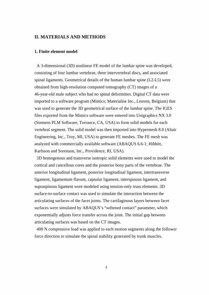
II. MATERIALS AND METHODS 1. Finite element model
A 3-dimensional (3D) nonlinear FE model of the lumbar spine was developed,
consisting of four lumbar vertebrae, three intervertebral discs, and associated spinal ligaments. Geometrical details of the human lumbar spine (L2-L5) were obtained from high-resolution computed tomography (CT) images of a 46-year-old male subject who had no spinal deformities. Digital CT data were imported to a software program (Mimics; Materialise Inc., Leuven, Belgium) that was used to generate the 3D geometrical surface of the lumbar spine. The IGES files exported from the Mimics software were entered into Unigraphics NX 3.0 (Siemens PLM Software, Torrance, CA, USA) to form solid models for each vertebral segment. The solid model was then imported into Hypermesh 8.0 (Altair Engineering, Inc., Troy, MI, USA) to generate FE meshes. The FE mesh was analyzed with commercially available software (ABAQUS 6.6-1; Hibbitt, Karlsson and Sorenson, Inc., Providence, RI, USA).
3D homogenous and transverse isotropic solid elements were used to model the cortical and cancellous cores and the posterior bony parts of the vertebrae. The anterior longitudinal ligament, posterior longitudinal ligament, intertransverse ligament, ligamentum flavum, capsular ligament, interspinous ligament, and supraspinous ligament were modeled using tension-only truss elements. 3D surface-to-surface contact was used to simulate the interaction between the articulating surfaces of the facet joints. The cartilaginous layers between facet surfaces were simulated by ABAQUS’s “softened contact” parameter, which exponentially adjusts force transfer across the joint. The initial gap between articulating surfaces was based on the CT images. 400 N compressive load was applied to each motion segments along the follower force direction to simulate the spinal stability generated by trunk muscles.
5
2. Material properties
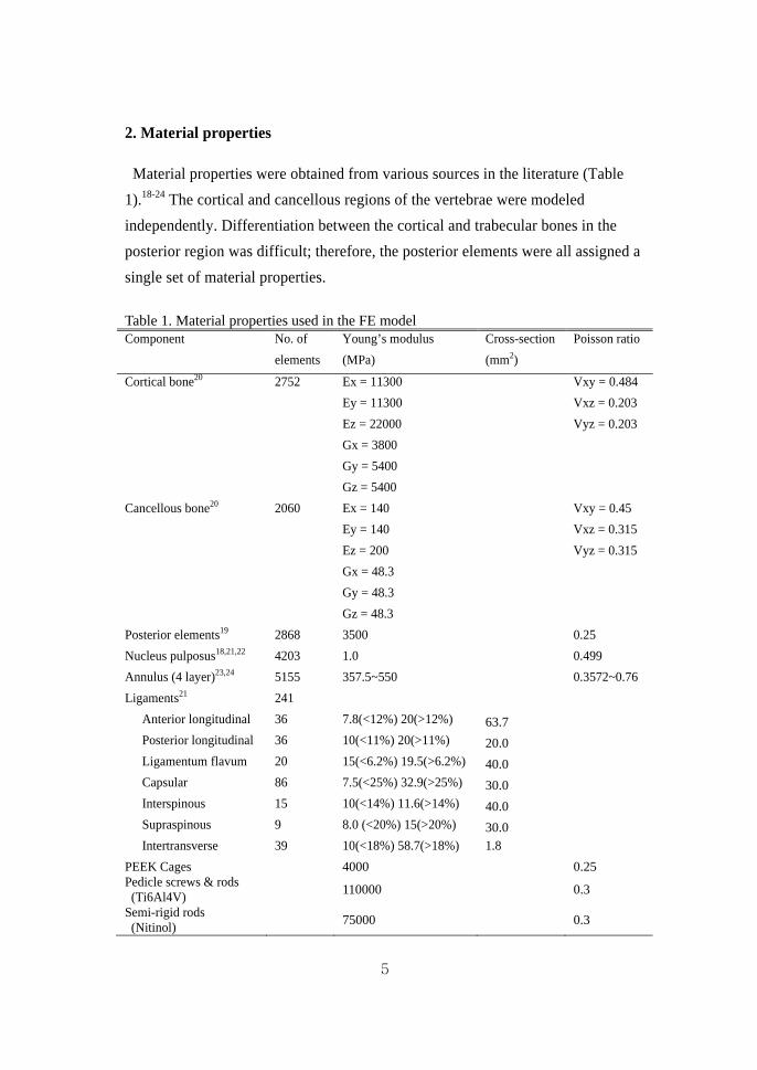
Material properties were obtained from various sources in the literature (Table 1).18-24 The cortical and cancellous regions of the vertebrae were modeled independently. Differentiation between the cortical and trabecular bones in the posterior region was difficult; therefore, the posterior elements were all assigned a single set of material properties. Table 1. Material properties used in the FE model Component No. of
elements Young’s modulus (MPa)
Cross-section (mm2)
Poisson ratio
Cortical bone20 2752 Ex = 11300 Vxy = 0.484 Ey = 11300 Vxz = 0.203 Ez = 22000 Vyz = 0.203 Gx = 3800 Gy = 5400 Gz = 5400
Cancellous bone20 2060 Ex = 140 Vxy = 0.45 Ey = 140 Vxz = 0.315 Ez = 200 Vyz = 0.315 Gx = 48.3 Gy = 48.3 Gz = 48.3
Posterior elements19 2868 3500 0.25 Nucleus pulposus18,21,22 4203 1.0 0.499 Annulus (4 layer)23,24 5155 357.5~550 0.3572~0.76 Ligaments21 241
Anterior longitudinal 36 7.8(<12%) 20(>12%) 63.7 Posterior longitudinal 36 10(<11%) 20(>11%) 20.0 Ligamentum flavum 20 15(<6.2%) 19.5(>6.2%) 40.0 Capsular 86 7.5(<25%) 32.9(>25%) 30.0 Interspinous 15 10(<14%) 11.6(>14%) 40.0 Supraspinous 9 8.0 (<20%) 15(>20%) 30.0 Intertransverse 39 10(<18%) 58.7(>18%) 1.8
PEEK Cages 4000 0.25 Pedicle screws & rods (Ti6Al4V) 110000 0.3
Semi-rigid rods (Nitinol) 75000 0.3
6
The fibers of the annulus fibrosis of the intervertebral disc were designed to have proportionally decreased elastic strength, from the outermost layer to the innermost, based on previous studies.23,24 The nucleus pulposus was modeled as nearly incompressible. Spinal ligaments were represented by nonlinear material properties. Naturally changing ligament stiffness (initial low stiffness at low strain, followed by increasing stiffness at higher strain) was simulated using the “hypoelastic” material designation. 3D truss elements were used to simulate ligaments, which were active only in tension.
3. Arthrodesis models
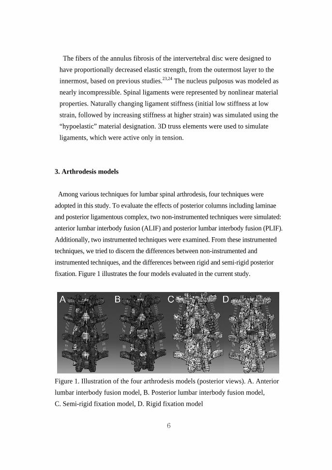
Among various techniques for lumbar spinal arthrodesis, four techniques were
adopted in this study. To evaluate the effects of posterior columns including laminae and posterior ligamentous complex, two non-instrumented techniques were simulated: anterior lumbar interbody fusion (ALIF) and posterior lumbar interbody fusion (PLIF). Additionally, two instrumented techniques were examined. From these instrumented techniques, we tried to discern the differences between non-instrumented and instrumented techniques, and the differences between rigid and semi-rigid posterior fixation. Figure 1 illustrates the four models evaluated in the current study.
Figure 1. Illustration of the four arthrodesis models (posterior views). A. Anterior lumbar interbody fusion model, B. Posterior lumbar interbody fusion model, C. Semi-rigid fixation model, D. Rigid fixation model
7
A. Anterior lumbar interbody fusion model
To simulate the ALIF model, the medial portion of the anterior longitudinal ligament (ALL) and the anterior annulus were excised, and whole nucleus pulposus was removed at the L3/4 level of the intact model. The intervertebral disc and the endplates between L3 and L4 were totally replaced by the bone graft and two cages. To mimic bony fusion, which is the purpose of arthrodesis, bone graft and cages were bonded to the inferior cortical bone of L3 and the superior cortical bone of L4 by means of a “tie” contact condition with full constraint.
B. Posterior lumbar interbody fusion model
To make the PLIF model, subtotal laminectomy and medial facetectomy of intact model were performed at the L3/4 level, including the removal of supraspinous, interspinous, and flavum ligaments. Then, the medial part of posterior longitudinal ligament (PLL) and posterior annulus was excised. Interbody fusion was simulated in the same way as in the ALIF model.
C. Semi-rigid fixation model
The semi-rigid fixation model was made from the PLIF model. The screws were
inserted into the pedicles of L3 and L4. Insertion of the screws was performed
horizontally with an inward inclination of 10 degrees. The diameter of all the
pedicle screws was assumed to be 5.0 mm, with a mean outer diameter of 6.5 mm
(including thread height). The length of the screws in L3 and L4 was 40 mm.
Nitinol semi-rigid rods were placed over screw heads and fixed to the screws.
D. Rigid fixation model
There was only one difference between the semi-rigid fixation model and the rigid fixation model, which was the replacement of Nitinol semi-rigid rods with titanium alloy (Ti6Al4V) rigid rods.
8
4. Boundary and loading conditions
This FE investigation of loading conditions corresponds to loads used in the experimental part of the study25 for model validation and model predictions for clinically relevant loading scenarios. Validation included loading the model with 10 Nm moments. The nodes of the inferior surfaces of the inferior-most vertebral body were completely fixed in all directions. To validate the model, the same loading conditions used in Yamamoto et al. were applied.25 The nodes on top of the L2 vertebra were defined as the coupling nodes. A reference node was created and connected to each coupling node. A coupling element was created to distribute moments on the reference node. As such, 10 Nm of flexion, 10 Nm of extension, 10 Nm of torsion, and 10 Nm of lateral bending under the 150 N preload were imposed on the L2 vertebral body. To reach 10 Nm moments, the five load steps were applied. The second type of loading condition was the hybrid testing protocol, which was implemented during flexibility testing of the FE models as described by Goel et al for the study of adjacent level biomechanics (intradiscal pressure and facet contact force).26 This protocol involved the applied pure moment for the intact and four fusion models until its L2-L5 rotation (displacement) equaled the intact load control case values; this was done by imposing 7.5 Nm extension and torsion moments on the L2 vertebral body in the intact model.
9
III. RESULTS 1. Model validation
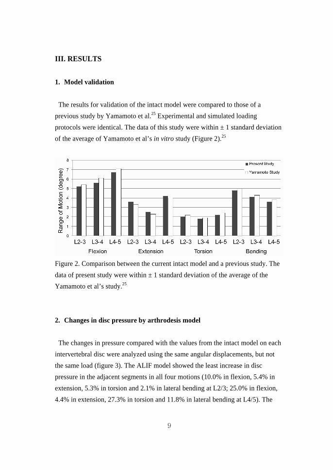
The results for validation of the intact model were compared to those of a previous study by Yamamoto et al.25 Experimental and simulated loading protocols were identical. The data of this study were within ± 1 standard deviation of the average of Yamamoto et al’s in vitro study (Figure 2).25
Figure 2. Comparison between the current intact model and a previous study. The data of present study were within ± 1 standard deviation of the average of the Yamamoto et al’s study.25 2. Changes in disc pressure by arthrodesis model
The changes in pressure compared with the values from the intact model on each intervertebral disc were analyzed using the same angular displacements, but not the same load (figure 3). The ALIF model showed the least increase in disc pressure in the adjacent segments in all four motions (10.0% in flexion, 5.4% in extension, 5.3% in torsion and 2.1% in lateral bending at L2/3; 25.0% in flexion, 4.4% in extension, 27.3% in torsion and 11.8% in lateral bending at L4/5). The

10
PLIF model showed a 26.7% increase in disc pressure in flexion, 5.4% in extension, 15.8% in torsion and 6.4% in lateral bending at L2/3; 16.7% in flexion, 4.4% in extension, 63.6% in torsion and 23.5% in lateral bending at L4/5. The largest increase in disc pressure was seen in the rigid fixation model (73.3% in flexion, 18.9% in extension, 47.4% in torsion and 17.0% in lateral bending at L2/3; 75.0% in flexion, 77.8% in extension, 118.2% in torsion and 47.1% in lateral bending at L4/5). The increase in disc pressure in the adjacent segments of the semi-rigid fixation model was less than that of the rigid fixation model, and more than that of the PLIF model (56.7% in flexion, 5.4% in extension, 36.8% in torsion and 6.4% in lateral bending at L2/3; 58.3% in flexion, 6.7% in extension, 109.4% in torsion and 41.2% in lateral bending at L4/5).
Figure 3. Disc pressure increase of arthrodesis models compared with intact model. 3. Changes in facet joint contact force by arthrodesis model
The increase in contact force of adjacent facet joints showed similar patterns to those of disc pressure (figure 4). The smallest increase in contact force of the adjacent facet joints was seen in the ALIF model (10.5% in extension, and 13.3% in torsion at L2/3; 28.6% in extension, and 13.6% in torsion at L4/5). The increase in contact force in the PLIF model was 10.5% in extension, and 32.3% in torsion at L2/3; 32.1% in extension, and 22.7% in torsion at L4/5. The semi-rigid model showed a 15.8% increase in contact force in extension and 50.0% in torsion at

11
L2/3; 42.9% in extension, and 45.5% in torsion at L4/5. The largest increase in contact force was seen in the rigid fixation model (36.8% in extension, and 63.3% in torsion at L2/3; 64.3% in extension, and 54.5% in torsion at L4/5), as was the largest increase in disc pressure.
Figure 4. Contact force increase of arthrodesis models compared with intact model.

12
IV. DISCUSSION The results of this study showed that the effects of arthrodesis on adjacent segments were different depending on the surgical technique used. These differences resulted from the status of the posterior elements, which are comprised of the medial portion of the facet joints, laminae, posterior ligament complex, pedicle screws and instrumented fixation. The medial portion of facet joints, laminae, and posterior ligament complex shared and decreased the stress from the motion at the adjacent segments, especially in flexion and torsion. However, this did not have much of an effect when compared with the effect of posterior instrumented fixation. Arthrodesis with rigid and semi-rigid posterior fixation caused more increase in disc pressure and contact force at the adjacent segments than arthrodesis without posterior fixation. In addition, the increase in disc pressure and contact force differed according to the rigidity of the posterior fixation. Posterior rigid fixation resulted in an increase in stress four or five times higher on the adjacent segments in flexion and torsion than ALIF. Posterior semi-rigid fixation also increased the work-load of the adjacent segments, but the increase was smaller than that of posterior rigid fixation. In extension and lateral bending, the effects of posterior semi-rigid fixation were similar to those of PLIF. As mentioned previously, posterior rigid fixation in lumbar arthrodesis gives more stabilization and a higher fusion rate. However, posterior rigid fixation caused more stress on the adjacent segment in this study. It is thought that the posterior semi-rigid fixation can preserve the merits and compensate for the demerits of rigid fixation in lumbar arthrodesis. However, more studies are necessary to prove this, including clinical studies of the fusion rate, or in vivo biomechanical studies. Cost-effectiveness should also be considered. While recent reports about semi-rigid or dynamic rods seem to be focused on dynamic stabilization without fusion,27,28 semi-rigid fixation combined with arthrodesis deserves careful consideration.

13
V. CONCLUSION Depending on the technique used for lumbar arthrodesis, the increases in disc pressure of the intervertebral discs and in contact force of the facet joints of the adjacent segments were found to be different. Semi-rigid fixation appears to be able to decrease the stress of the adjacent segment after lumbar arthrodesis when compared with rigid fixation. In order to more precisely evaluate the benefits and losses of semi-rigid fixation, in vivo and clinical studies are necessary.

14
REFERENCES 1. Bono CM, Lee CK. Critical analysis of trends in fusion for
degenerative disc disease over the past 20 years: influence of
technique on fusion rate and clinical outcome. Spine (Phila Pa 1976)
2004;29:455-63; discussion Z5.
2. Bridwell KH, Sedgewick TA, O'Brien MF, Lenke LG, Baldus C. The
role of fusion and instrumentation in the treatment of degenerative
spondylolisthesis with spinal stenosis. J Spinal Disord 1993;6:461-72.
3. Fischgrund JS, Mackay M, Herkowitz HN, Brower R, Montgomery DM,
Kurz LT. 1997 Volvo Award winner in clinical studies. Degenerative
lumbar spondylolisthesis with spinal stenosis: a prospective,
randomized study comparing decompressive laminectomy and
arthrodesis with and without spinal instrumentation. Spine (Phila Pa
1976) 1997;22:2807-12.
4. Cheh G, Bridwell KH, Lenke LG, Buchowski JM, Daubs MD, Kim Y, et
al. Adjacent segment disease followinglumbar/thoracolumbar fusion
with pedicle screw instrumentation: a minimum 5-year follow-up.
Spine (Phila Pa 1976) 2007;32:2253-7.
5. Park P, Garton HJ, Gala VC, Hoff JT, McGillicuddy JE. Adjacent
segment disease after lumbar or lumbosacral fusion: review of the
literature. Spine (Phila Pa 1976) 2004;29:1938-44.
6. Booth KC, Bridwell KH, Eisenberg BA, Baldus CR, Lenke LG. Minimum
5-year results of degenerative spondylolisthesis treated with
decompression and instrumented posterior fusion. Spine (Phila Pa
1976) 1999;24:1721-7.
7. Chen WJ, Niu CC, Chen LH, Shih CH. Survivorship analysis of DKS
instrumentation in the treatment of spondylolisthesis. Clin Orthop
Relat Res 1997:113-20.
8. Etebar S, Cahill DW. Risk factors for adjacent-segment failure
following lumbar fixation with rigid instrumentation for degenerative
instability. J Neurosurg 1999;90:163-9.
9. Ghiselli G, Wang JC, Bhatia NN, Hsu WK, Dawson EG. Adjacent
segment degeneration in the lumbar spine. J Bone Joint Surg Am
2004;86-A:1497-503.
10. Gillet P. The fate of the adjacent motion segments after lumbar fusion.
J Spinal Disord Tech 2003;16:338-45.
11. Guigui P, Wodecki P, Bizot P, Lambert P, Chaumeil G, Deburge A.
[Long-term influence of associated arthrodesis on adjacent segments
in the treatment of lumbar stenosis: a series of 127 cases with 9-year
follow-up]. Rev Chir Orthop Reparatrice Appar Mot 2000;86:546-57.

15
12. Harrop JS, Youssef JA, Maltenfort M, Vorwald P, Jabbour P, Bono CM,
et al. Lumbar adjacent segment degeneration and disease after
arthrodesis and total disc arthroplasty. Spine (Phila Pa 1976)
2008;33:1701-7.
13. Kumar MN, Baklanov A, Chopin D. Correlation between sagittal plane
changes and adjacent segment degeneration following lumbar spine
fusion. Eur Spine J 2001;10:314-9.
14. Kumar MN, Jacquot F, Hall H. Long-term follow-up of functional
outcomes and radiographic changes at adjacent levels following
lumbar spine fusion for degenerative disc disease. Eur Spine J
2001;10:309-13.
15. Rahm MD, Hall BB. Adjacent-segment degeneration after lumbar
fusion with instrumentation: a retrospective study. J Spinal Disord
1996;9:392-400.
16. Sears WR, Sergides IG, Kazemi N, Smith M, White GJ, Osburg B.
Incidence and prevalence of surgery at segments adjacent to a
previous posterior lumbar arthrodesis. Spine J 2011;11:11-20.
17. Wai EK, Santos ER, Morcom RA, Fraser RD. Magnetic resonance
imaging 20 years after anterior lumbar interbody fusion. Spine (Phila
Pa 1976) 2006;31:1952-6.
18. Chen CS, Cheng CK, Liu CL, Lo WH. Stress analysis of the disc
adjacent to interbody fusion in lumbar spine. Med Eng Phys
2001;23:483-91.
19. Goel VK, Monroe BT, Gilbertson LG, Brinckmann P. Interlaminar shear
stresses and laminae separation in a disc. Finite element analysis of
the L3-L4 motion segment subjected to axial compressive loads.
Spine (Phila Pa 1976) 1995;20:689-98.
20. Lu YM, Hutton WC, Gharpuray VM. Do bending, twisting, and diurnal
fluid changes in the disc affect the propensity to prolapse? A
viscoelastic finite element model. Spine (Phila Pa 1976)
1996;21:2570-9.
21. Pintar FA, Yoganandan N, Myers T, Elhagediab A, Sances A, Jr.
Biomechanical properties of human lumbar spine ligaments. J Biomech
1992;25:1351-6.
22. Wu HC, Yao RF. Mechanical behavior of the human annulus fibrosus. J
Biomech 1976;9:1-7.
23. Polikeit A, Ferguson SJ, Nolte LP, Orr TE. Factors influencing
stresses in the lumbar spine after the insertion of intervertebral
cages: finite element analysis. Eur Spine J 2003;12:413-20.
24. Shirazi-Adl A, Ahmed AM, Shrivastava SC. Mechanical response of a
lumbar motion segment in axial torque alone and combined with
compression. Spine (Phila Pa 1976) 1986;11:914-27.
16
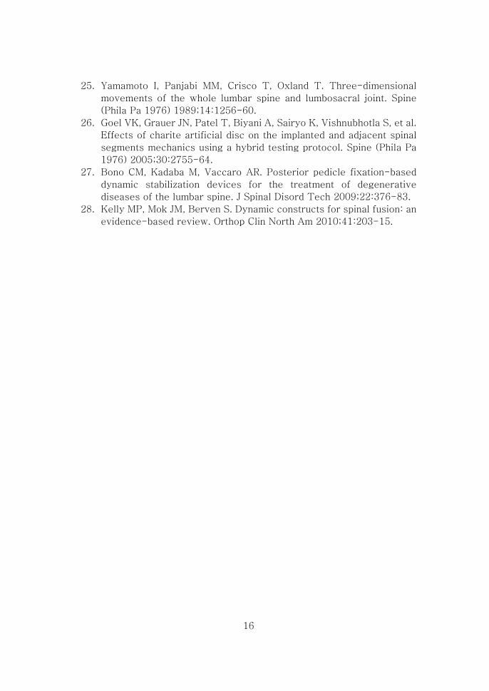
25. Yamamoto I, Panjabi MM, Crisco T, Oxland T. Three-dimensional
movements of the whole lumbar spine and lumbosacral joint. Spine
(Phila Pa 1976) 1989;14:1256-60.
26. Goel VK, Grauer JN, Patel T, Biyani A, Sairyo K, Vishnubhotla S, et al.
Effects of charite artificial disc on the implanted and adjacent spinal
segments mechanics using a hybrid testing protocol. Spine (Phila Pa
1976) 2005;30:2755-64.
27. Bono CM, Kadaba M, Vaccaro AR. Posterior pedicle fixation-based
dynamic stabilization devices for the treatment of degenerative
diseases of the lumbar spine. J Spinal Disord Tech 2009;22:376-83.
28. Kelly MP, Mok JM, Berven S. Dynamic constructs for spinal fusion: an
evidence-based review. Orthop Clin North Am 2010;41:203-15.
17
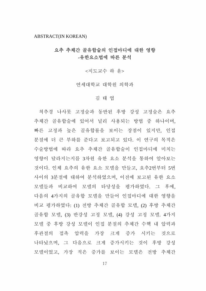
ABSTRACT(IN KOREAN)
요추 추체간 골유합술의 인접마디에 대한 영향 -유한요소법에 따른 분석
<지도교수 하 윤>
연세대학교 대학원 의학과
김 태 엽
척추경 나사못 고정술과 동반된 후방 강성 고정술은 요추
추체간 골유합술에 있어서 널리 사용되는 방법 중 하나이며,
빠른 고정과 높은 골유합률을 보이는 장점이 있지만, 인접
분절에 더 큰 부하를 준다고 보고되고 있다. 이 연구의 목적은
수술방법에 따라 요추 추체간 골유합술이 인접마디에 미치는
영향이 달라지는지를 3차원 유한 요소 분석을 통하여 알아보는
것이다. 인체 요추의 유한 요소 모델을 만들고, 요추2번부터 5번
사이의 3분절에 대하여 분석하였으며, 이전에 보고된 유한 요소
모델들과 비교하여 모델의 타당성을 평가하였다. 그 후에,
다음의 4가지의 골유합 모델을 만들어 인접마디에 대한 영향을
비교 평가하였다: (1) 전방 추체간 골유합 모델, (2) 후방 추체간
골유합 모델, (3) 반강성 고정 모델, (4) 강성 고정 모델. 4가지
모델 중 후방 강성 모델이 인접 분절의 추체간 수핵 내 압력과
후관절의 접촉 압력을 가장 크게 증가 시키는 것으로
나타났으며, 그 다음으로 크게 증가시키는 것이 후방 강성
모델이었고, 가장 적은 증가를 보이는 모델은 전방 추체간

18
골유합 모델이었다. 이러한 결과로부터, 요추 추체간 골유합술이
인접마디에 미치는 영향은 사용된 수술 방법에 따라 달라진다는
것을 알 수 있었으며, 반강성 고정술은 강성 고정술의 장점은
유지하면서 인접마디에 미치는 영향은 줄일 수 있을 것으로
판단되기 때문에 이에 대한 관심과 추가 연구가 이루어져야 할
것으로 생각된다.
핵심되는 말: 요추, 인접마디, 골유합술, 동적고정, 반강성고정, 유한 요소 분석