effectiveness of horizontal drains for slope stability - researchgate
TRANSCRIPT

Effectiveness of horizontal drains for slope stability
H. Rahardjoa,*, K.J. Hritzuka, E.C. Leongb,1, R.B. Rezaurc,2
aSchool of Civil and Environmental Engineering, Nanyang Technological University, Blk N1, #1A-02, Nanyang Avenue,
Singapore 639798, SingaporebSchool of Civil and Environmental Engineering, Nanyang Technological University, Blk N1, #1C-80, Nanyang Avenue,
Singapore 639798, SingaporecSchool of Civil and Environmental Engineering, Nanyang Technological University, Blk N1, #B4-06, Nanyang Avenue,
Singapore 639798, Singapore
Received 29 August 2002; accepted 11 December 2002
Abstract
Horizontal drains have been commonly used in stabilising unsaturated residual soil slopes. This study examines the
effectiveness of horizontal drains in stabilising residual soil slopes against rainfall-induced slope failures under a tropical
climate. The study includes field instrumentation at two residual soil slopes complemented with a parametric study relating to
drain position. Field monitoring results indicate that rainfall infiltration is limited to a certain depth below which infiltration
becomes insignificant. This zone tends to be unsuitable for horizontal drains. Horizontal drains were found to be most effective
when located at the base of a slope. The parametric study indicated conditions under which horizontal drains are effective or
ineffective in improving the stability of a slope. It was also found that horizontal drains have little role in minimising infiltration
in an unsaturated residual soil slope. Benefits of using horizontal drains can be obtained through the lowering of the water table.
D 2003 Elsevier Science B.V. All rights reserved.
Keywords: Rainfall-induced slope failure; Horizontal drain; Residual soils; Pore–water pressure; Tensiometer
1. Introduction
Singapore is located in the tropics where heavy
rainfalls and high temperatures provide conditions for
rapid and thorough in-situ chemical and mechanical
weathering that result in the development of deep
residual soil profiles. Because of the frequent high
intensity tropical rainfalls, slope failures are common
in this region.
Pierson et al. (1992) observed that landslides in
Hawaii coincided with or followed an extremely heavy
rainfall. Studies of slope failures in Hong Kong
(Brand, 1992) and in Singapore (Pitts, 1985; Tan et
al., 1987; Toll et al., 1999; Rahardjo et al., 2001) also
showed the destabilising effects of short duration, high
intensity rainfalls. Some studies have also shown the
effects of rainfall on residual soil slopes by pore–water
pressure measurements using piezometric and matric
suction (Fredlund and Rahardjo, 1993) measuring
0013-7952/03/$ - see front matter D 2003 Elsevier Science B.V. All rights reserved.
doi:10.1016/S0013-7952(02)00288-0
* Corresponding author. Tel.: +65-6790-4104; fax: +65-6791-
0676.
E-mail addresses: [email protected] (H. Rahardjo),
[email protected] (E.C. Leong), [email protected]
(R.B. Rezaur).
URL: http://www.ntu.edu.sg/cse/.1 Tel.: +65-6790-4774; fax: +65-6791-0676.2 Tel.: +65-6790-6199; fax: +65-6791-0676.
www.elsevier.com/locate/enggeo
Engineering Geology 69 (2003) 295–308

devices (e.g., Pitts, 1985; Lim et al., 1996; Rahardjo
et al., 1998, 2000). In a study in Singapore, Lim et al.
(1996) showed that, in general, matric suction in the
soil increased during dry periods when evaporation
was predominant, resulting in increased shear
strength. Matric suction and shear strength decreased
during wet periods when infiltration was predomi-
nant. Maximum changes were found to occur near
the ground surface. Short duration rainfalls were
shown to leave a considerable amount of matric
suction in the soil, but prolonged heavy rainfalls
destroyed matric suction in the soil zone near the
ground surface even to the extent that a perched
water table would be formed.
The use of horizontal drains as a preventive meas-
ure is a common practice in the region. Horizontal
drains are defined as holes drilled into a cut slope or
embankment and cased with a perforated metal or
slotted plastic liner (Royster, 1980). The purpose of
using horizontal drains as part of landslide control
work is to drain away groundwater, thus keeping the
soil dry. The design and success of these measures are
often governed by local experience alone. The effec-
tiveness of the horizontal drainage system is a func-
tion of many factors including the drain location,
length and spacing, as well as soil properties and
slope geometry. Typically, effectiveness is described
in terms of increase in slope factor of safety as
compared to factor of safety for the case without
horizontal drains. There have been a few studies
(Royster, 1980; Lau and Kenney, 1984; Martin et
al., 1994), which attempted to describe in part the
many parameters controlling the horizontal drainage
design or evaluate the feasibility of using a system of
horizontal drains to lower groundwater levels in hill-
sides (e.g., Craig and Gray, 1985). Martin et al. (1994)
suggested that a small number of drains installed at
appropriate locations in accordance with a well-con-
ceived conceptual groundwater model may be more
effective than a large number of drains installed at
uniform spacing over the slope. Presently, there seems
to be limited information available in the literature in
the area of horizontal drainage.
Negative pore–water pressure or matric suction
(when referenced to pore–air pressure) plays a crucial
role in the stability of earthworks. Although its
importance has been identified, it is not often under-
stood and therefore ignored in many geotechnical
designs. Avoidance of principles of unsaturated soil
mechanics can be attributed to two main reasons. The
first reason is the development of unsaturated soil
mechanics has lagged in comparison to saturated soil
mechanics. Secondly, those who are aware of it will
often question whether or not the negative pore–water
pressure can be maintained throughout the lifetime of
a design. It is for this second reason that this study
was undertaken by attempting to show that dewatering
methods can be used to aid in the control of negative
pore–water pressures in a slope. Thus, it is expected
that the negative pore–water pressure or matric suc-
tion will not be destroyed and can therefore be in-
cluded in design.
2. Field study
Since the destabilisation effects of rainfall infiltra-
tion on slopes are clear, a study was undertaken to
investigate the influence of horizontal drains on
slope stability (Hritzuk, 1997). Two different sites
(NTU-CSE slope and Nanyang Heights slope),
located on the Nanyang Technological University
(NTU) campus in Singapore, were used in this
investigation. The locations of the slopes are shown
in Fig. 1. Both slopes were instrumented to monitor
the effectiveness of the drainage system as related to
rainfall.
The geology of Singapore consists of three for-
mations: (a) igneous rocks of granitic or similar
composition (Bukit Timah Granite) in the center and
northwest region, (b) sedimentary rocks (Jurong For-
mation) occupying the west region and (c) a semi-
hardened alluvium (Old Alluvium), which masks older
rocks beneath in the eastern region (PWD, 1976). The
oldest rock in Singapore, Bukit Timah Granite, prob-
ably comes from the Plaeozoic era, which ended about
225 million years ago. Granite occurs in two separate
masses. The larger one is found in the central and
northern areas; the smaller one in parts of northern
Singapore. According to radioactive age determina-
tion, the granite in Singapore is more than 200 million
years old (Leong et al., 2002). The sedimentary rocks
of the Jurong Formation skirt the central granite and
form extensive areas in the southwest, southwestern
and western Singapore. The Jurong formation is
composed of a series of sedimentary rocks such as
H. Rahardjo et al. / Engineering Geology 69 (2003) 295–308296

sandstone, siltsone, mudstone, shale, tuff, conglom-
erate and limestone. The formation has been severely
folded and faulted in the past as a result of tectonic
movements. The semi-hardened Old Alluvium was
deposited by an ancient river system, probably in the
Pleistocene epoch, during a low stand of the sea.
Residual soils of the granitic and sedimentary rocks
occupy about two-thirds of the land area of Singapore.
The present day configuration and much of the
morphology of the low-lying areas of Singapore is a
result of erosion and deposition during the period of
fluctuating sea levels in the late Tertiary and Quater-
nary. As sea level rose after the end of the last cold
stage about 11,000 years ago, it formed Singapore a
group of islands, separated from the Malay Peninsular
by the straits of Johor. Extensive marine clay, beach
deposits and associate terrestrial sediments were
deposited around the rocky flanks of the island
(Leong et al., 2002).
The relief of Singapore is relatively gentle. Only
10% of the land area is over 30 m high and more than
60% of the land is less than 15 m high (Pitts, 1984a).
The area of granitic and other igneous rocks in the
center of the island forms a landscape of rounded
hills and gentle spurs and valleys. The coast is flat,
but in few places cliffs can be found. Considerable
stretches of the coastline have been markedly modi-
fied by reclamation work, building of embankments
and swamp clearances.
The NTU campus is located on the sedimentary
rocks of Jurong formation. The geological formations
at the NTU campus are very complex as the area has
been subjected to intrusions, isoclinical overfolds and
faults in the past (Pitts, 1984a,b). The general strike of
Fig. 1. Location of NTU-CSE and Nanyang Heights slopes.
H. Rahardjo et al. / Engineering Geology 69 (2003) 295–308 297

the Jurong formation is northwest/southeast and the
dips of the formation may vary over short distance from
a few degrees to vertical or overturned (Leong et al.,
2002). There are a number of major and minor faults in
the Jurong formation with displacement ranging from
unknown distances to a few decimeters. The major
faults are normally infilled with clay gouge, which is
extremely soft when wet. The upper portions of the
Jurong Formation have been heavily weathered into
residual soils of clayey silts to silty clays. Both instru-
mented slopes on the NTU campus consist of residual
soils from the Jurong sedimentary formation overlying
siltstone and sandstone as the bedrock.
2.1. Site description, instrumentation and monitoring
results
2.1.1. NTU-CSE slope
The slope surface of the NTU-CSE site measured
approximately 10 m wide by 24 m long rising at 2:1
Fig. 2. Layout of instrumentation and soil profile characteristics at NTU-CSE slope: (a) Plan view, (b) Section A-A.
H. Rahardjo et al. / Engineering Geology 69 (2003) 295–308298

(H:V) to a height of about 12 m. Twelve horizontal
drains made from 6-m long and 89-mm diameter
perforated PVC pipes were wrapped in a geofilter
and installed in four rows in the study area (Fig. 2a
and b). Each row contained three drains, which were
spaced at 2-m intervals and inclined at a 10% gra-
dient. Thirty tensiometers were installed to measure
matric suctions at varying depths amongst the drains
(Area A, Fig. 2a). Another 35 tensiometers were
installed approximately 7 m away from the drained
area (Area B, Fig. 2a) for another study (Gasmo,
1997), but serves as a point of comparison between
drained and undrained conditions. Five piezometers
and a rain gauge were installed within the instru-
mented area. All instruments were connected to a
computer data acquisition system located in the Geo-
technic Laboratory near the site. A schematic diagram
of the instrument layout and soil profile characteristics
are shown in Fig. 2a and b.
Based on the borehole profiles through this site, it
was determined that the soil zone being studied was
typically a tropical residual soil of one soil type: a
dark purple hard and brittle silty clay, which in some
locations contained fine streaks of white clay. This
purple silty clay was overlain by a shallow layer of
light brownish orange silty clay mottled with some
white clay at the crest of the slope. The soil proper-
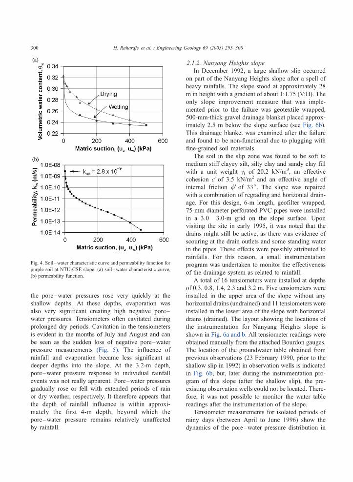
ties are given in Table 1, and the soil–water char-
acteristic curves and permeability functions for the
orange and purple soils are shown in Figs. 3 and 4,
respectively.
A 4-month data set was compiled from the
instrumentation of this site. Tensiometer data from
most of this zone showed that the slope remained
unsaturated during this period. On some occasions,
pore–water pressures would go slightly positive in a
few specific locations but the average pore–water
pressure at each depth remained negative (Fig. 5). A
similar depth of infiltration and pore–water pressure
response was found for the undrained section. Fig. 5
demonstrates that pore–water pressures were very
dynamic (i.e., changed frequently in response to
climatic conditions) at the 0.3-m depth due to rainfall
events and dry periods where the infiltration and
evaporation took place, respectively. During rainfalls,
Table 1
Properties of two soil types found at NTU-CSE slope
Properties (1) Purple soil (2) Orange soil (3)
Effective cohesion, cV 90 kPa 20 kPa
Effective angle of internal
friction, /V35.0j 26.5j
/b angle (angle indicating
the rate of a change in
shear strength relative to
a change in matric suction)
35.0j 23.0j
Saturated coefficient of
permeability, ks
2.8� 10� 9 m/s 7.8� 10� 7 m/s
Saturated density, qsat 2.30 Mg/m3 2.14 Mg/m3
Saturated water content, wsat 14.0% 28.8%
Specific gravity, Gs 2.72 2.67
Liquid limit, LL 34.0% 47.0%
Plasticity index, PI 13.5% 21.0%
Sand 15% 23%
Silt 42% 26%
Clay 43% 51%
USCS group symbol CL CL
USCS: Unified Soil Classification System.
Fig. 3. Soil–water characteristic curve and permeability function for
orange soil at NTU-CSE slope: (a) soil –water characteristic curve,
(b) permeability function.
H. Rahardjo et al. / Engineering Geology 69 (2003) 295–308 299
the pore–water pressures rose very quickly at the
shallow depths. At these depths, evaporation was
also very significant creating high negative pore–
water pressures. Tensiometers often cavitated during
prolonged dry periods. Cavitation in the tensiometers
is evident in the months of July and August and can
be seen as the sudden loss of negative pore–water
pressure measurements (Fig. 5). The influence of
rainfall and evaporation became less significant at
deeper depths into the slope. At the 3.2-m depth,
pore–water pressure response to individual rainfall
events was not really apparent. Pore–water pressures
gradually rose or fell with extended periods of rain
or dry weather, respectively. It therefore appears that
the depth of rainfall influence is within approxi-
mately the first 4-m depth, beyond which the
pore–water pressure remains relatively unaffected
by rainfall.
2.1.2. Nanyang Heights slope
In December 1992, a large shallow slip occurred
on part of the Nanyang Heights slope after a spell of
heavy rainfalls. The slope stood at approximately 28
m in height with a gradient of about 1:1.75 (V:H). The
only slope improvement measure that was imple-
mented prior to the failure was geotextile wrapped,
500-mm-thick gravel drainage blanket placed approx-
imately 2.5 m below the slope surface (see Fig. 6b).
This drainage blanket was examined after the failure
and found to be non-functional due to plugging with
fine-grained soil materials.
The soil in the slip zone was found to be soft to
medium stiff clayey silt, silty clay and sandy clay fill
with a unit weight ct of 20.2 kN/m3, an effective
cohesion cVof 3.5 kN/m2 and an effective angle of
internal friction /Vof 33j. The slope was repaired
with a combination of regrading and horizontal drain-
age. For this design, 6-m length, geofilter wrapped,
75-mm diameter perforated PVC pipes were installed
in a 3.0� 3.0-m grid on the slope surface. Upon
visiting the site in early 1995, it was noted that the
drains might still be active, as there was evidence of
scouring at the drain outlets and some standing water
in the pipes. These effects were possibly attributed to
rainfalls. For this reason, a small instrumentation
program was undertaken to monitor the effectiveness
of the drainage system as related to rainfall.
A total of 16 tensiometers were installed at depths
of 0.3, 0.8, 1.4, 2.3 and 3.2 m. Five tensiometers were
installed in the upper area of the slope without any
horizontal drains (undrained) and 11 tensiometers were
installed in the lower area of the slope with horizontal
drains (drained). The layout showing the locations of
the instrumentation for Nanyang Heights slope is
shown in Fig. 6a and b. All tensiometer readings were
obtained manually from the attached Bourdon gauges.
The location of the groundwater table obtained from
previous observations (23 February 1990, prior to the
shallow slip in 1992) in observation wells is indicated
in Fig. 6b, but, later during the instrumentation pro-
gram of this slope (after the shallow slip), the pre-
existing observation wells could not be located. There-
fore, it was not possible to monitor the water table
readings after the instrumentation of the slope.
Tensiometer measurements for isolated periods of
rainy days (between April to June 1996) show the
dynamics of the pore–water pressure distribution in
Fig. 4. Soil–water characteristic curve and permeability function for
purple soil at NTU-CSE slope: (a) soil –water characteristic curve,
(b) permeability function.
H. Rahardjo et al. / Engineering Geology 69 (2003) 295–308300

the drained and undrained areas (Fig. 7a and b) at
Nanyang Heights over the course of a few days of
heavy rainfall. An extended period of dry weather
existed prior to each of these events. The measured
results from these events are summarized as pore–
water pressure profiles in Fig. 7a and b. Generally,
Fig. 5. Average pore–water pressure readings at various depths of the NTU-CSE slope: (a) monitoring period: April– June 1996, (b) monitoring
period: July–September 1996.
H. Rahardjo et al. / Engineering Geology 69 (2003) 295–308 301

Fig. 6. Layout of instrumentation and soil profile characteristics at Nanyang Heights slope: (a) Plan view, (b) Section A-A.
H. Rahardjo et al. / Engineering Geology 69 (2003) 295–308302

the pore–water pressures at all depths followed the
same trend, rising and falling at the same time with
respect to rainfall and evaporation. For the depths at
0.3, 0.8 and 1.4 m, very little distinction could be
made between the pore–water pressures in the
undrained and drained areas. At the 2.3- and 3.2-m
depths, there was a difference in pore–water pres-
sures between the undrained and drained area, which
was maintained at about 15 kPa. The validity of the
results obtained at 2.3 and 3.2 m in the undrained
area is questionable. Proper contact between soil and
the ceramic cup of the tensiometer may not have been
achieved and this may explain why these tensiometer
readings seemed to be relatively unresponsive when
compared with those in the drained area (see Fig. 7a
and b).
Based on site observations, a couple of drains were
found to be active after a series of heavy rainfalls
ending early June 1996. Fig. 7 does show that the soil
became saturated during rainfall. The resulting drain-
Fig. 7. Pore–water pressure profiles for drained and undrained area at Nanyang Heights slope: (a) drained area, (b) undrained area.
H. Rahardjo et al. / Engineering Geology 69 (2003) 295–308 303

age only appeared as small water droplets forming at
the drain outlet, which accumulated at a very slow
rate. Pore–water pressures at the surface tended to be
more negative than at deeper depths, but extended
rainfalls caused the negative pore–water pressures to
be eliminated. Fig. 7 also shows that full saturation
occurred down to a depth of about 2 m, which was
when the above mentioned drains started showing
activity. It indicates that the soils were still capable
of becoming saturated even though the drainage
system was in place. Therefore, these shallow drains
seemed to have little significance in removing infil-
trating rainwater.
Using the field monitoring results from NTU-CSE
and Nanyang Heights slopes, some general observa-
tions can be made. At NTU-CSE slope, it appears that
the negative pore–water pressure zone was not cre-
ated by the drainage system. If that were true, pore–
water pressures would have been positive for a sig-
nificant period of time (as in the case at Nanyang
Heights slope) and there would have been evidence of
seepage from the drain outlets. The negative pore–
water pressure zone existed simply because the water
table was located significantly deeper than the zone
with horizontal drainage. The maximum depth of the
piezometers was more than 10 m below the slope
surface and yet the piezometers remained empty. At
Nanyang Heights slope, drainage develops well after
the rainfall suggesting that the soil were drained too
slowly. Pore–water pressures would therefore have
built up and become most critical just at the end of the
rainfall. It seems that, whether the drains were present
or not, would be of no consequence to the pore–water
pressure condition within the slope.
An understanding of relationship between drainage
and infiltration in the upper few meters of a slope was
gained from NTU-CSE and Nanyang Heights slopes,
but data were inadequate to form a concept of the
function of horizontal drainage at deeper depths in the
vicinity of the main water table. As such, numerical
analysis was adopted to supplement the understanding
of the importance of drain location.
3. Parametric study
A parametric study was performed to investigate
the significance of drain location within a slope. The
seepage analysis was performed using the finite ele-
ment seepage software Seep/W (Geo-Slope, 1998a)
and the stability analysis was performed using the
limit equilibrium slope stability software Slope/W
(Geo-Slope, 1998b).
A homogeneous slope rising at 45j to a height of
30 m was used as the model for this parametric study.
The slope configuration, horizontal drainage location
and finite element mesh configuration for the para-
metric study are shown in Fig. 8a and b. Five
scenarios were analyzed based on different drainage
configurations. Three evenly spaced drain locations
were considered as shown in Fig. 8a. The first
scenario involved the slope configuration without
drainage. The next three scenarios involved the slope
configuration with each drain on its own and the fifth
scenario incorporated all three drains. Soil properties
used in this model were as follows: ct of 21.0 kN/m3,
an effective cohesion cVof 20 kPa and an effective
angle of internal friction /V of 26.5j, the angle
indicating the rate of a change in shear strength
relative to a change in matric suction (Fredlund and
Rahardjo, 1993) /b of 23j. The soil–water character-istic curve and permeability functions shown in Fig.
3a and b, respectively, were also used in conjunction
with these soil properties for the analysis.
Each horizontal drain was specified internally
along the edges of elements as a line of zero flux
and reviewed by maximum pressure. During the
iterative process, drain nodes were checked for instan-
ces where pressures were calculated to be greater than
zero. If such was the case, the nodal value was
adjusted back down to zero pressure or, in other
words, the total head was equated to the elevation
head. In the instance where pressures of the drain
nodes were less than the specified zero value, the
nodal values remain as such and were treated like any
other node. Therefore, there was no ‘backflow’ into
the slope model which would be the case if the drain
nodes were fixed at a constant zero pressure without
review and the surrounding region was unsaturated.
This review by maximum pressure allowed the model
to be representative of the case where one would
expect drains to be active only under positive pore-
water pressure conditions or in the saturated part of
the slope. If drains were in the unsaturated part of the
slope, the groundwater would move throughout the
slope as if the drains were not present at all.
H. Rahardjo et al. / Engineering Geology 69 (2003) 295–308304

Steady-state conditions were established for all
different drainage scenarios. The steady-state water
table was developed below the drained zones so that
each initial condition was identical. In other words,
the drainage configurations had no influence on the
initial conditions. Subsequently, a rainfall rate equal to
the saturated permeability was applied to the slope
and the transient process was monitored. Data from
each time step were saved over the course of the
transient analysis. The transient analysis was termi-
nated at a time, which showed no significant differ-
ence in seepage results from the previous time step.
The Seep/W program has a ‘flux line’ feature to
measure flow across any cross-section drawn in the
model prior to the analysis. Flux lines were used in
this model around each drain location and on the slope
surface. Flux lines drawn around drains incorporated a
zone of soil into which seepage flow was monitored
and compiled as flow per unit length across each flux
section. Flux values calculated for the slope surface
were not easily interpreted because there was a
countering effect of positive inflow across the boun-
dary in the form of rainfall and a negative outflow due
to the establishment of the seepage face on the slope.
Flux values in the vicinity of the drain locations
tended to be more reliable as there was no significant
multidirectional flow across the boundaries. Flux
values obtained for seepage flow through the bottom
zone for different drainage configuration are presented
in Fig. 9.
It was found that a totally unrealistic rainfall
condition and time frame were required to create a
Fig. 8. Finite element model for the parametric study: (a) slope configuration and horizontal drain location, (b) finite element mesh.
H. Rahardjo et al. / Engineering Geology 69 (2003) 295–308 305

significant change in the soil pore–water pressure. A
continuous rainfall rate equivalent to ks was applied to
the slope for all five drainage configurations until
equilibrium was achieved. It took more than 20,000
consecutive days of continuous rainfall in all cases in
order to achieve equilibrium. This meant that satura-
tion would never occur in this type of soil and there-
fore installing horizontal drains in such material
would be pointless. However, the model still served
the purpose of illustrating the relative benefits of drain
positioning.
A factor of safety was calculated for each drainage
scenario at every time step by importing the pore–
water pressure head files into Slope/W model. The
results of the slope stability analyses are shown in Fig.
10. The general trend of Fig. 10 shows that the least
amount of benefit was derived from the drains located
in the upper region of the slope. The most benefit was
derived from the drain located at the bottom of the
slope and a very small additional benefit was obtained
by combining the bottom drain with other drains in
the upper region. This is shown by comparing the
factor of safety obtained from the case with three
drains as opposed to the case with one drain at the
bottom of the slope. The condition with the three
drains only gives a 3% additional factor of safety as
compared to the condition with the bottom drain. The
reason for the slight difference in factor of safety is
that the bottom drain attracted the most water. It can
be seen in Fig. 9 that the seepage flow in the bottom
zone was relatively the same when either a single
drain was present in this bottom zone or if all three
drains were present in the slope. When the three
drains were present, the top and middle zones showed
approximately two orders of magnitude less flow than
the bottom drain. This again shows the bottom drain
as most efficient in draining out the water and main-
taining the stability of the slope.
4. Conclusions
Both the field study and parametric study show the
importance of locating a horizontal drain as low as
possible in the slope. It attracts the majority of
groundwater and has the largest effect on lowering
the water table. This confirms the findings of Lau and
Kenney (1984) and Martin et al. (1994). The para-
metric study has also shown that drains located in the
upper region of a slope are of no real significance as
long as a drain is already located in the lower part of a
slope. The water table will eventually be reduced to
the lowest drain level and any drains above the bottom
drain will no longer serve any significant use. It
appears that rainfall does not cause the water table
to rise much above the drainage zone once the water
table has been established at the lowest level. Martin
et al. (1994) has also noted similar behaviour.
Installing drains in the upper region of a slope for
the purpose of intercepting perched water tables and
infiltrating rainwater does not appear to be effective as
was evident from NTU-CSE and Nanyang Heights
slopes. This is consistent with observations made by
Martin et al. (1994). On very rare occasions, one or
two drains from the NTU-CSE and Nanyang HeightsFig. 9. Theoretical flux through bottom zone for various drainage
configurations.
Fig. 10. Theoretical factor of safety with respect to drain position for
a constant rainfall rate.
H. Rahardjo et al. / Engineering Geology 69 (2003) 295–308306

sites showed activity but only in the form of water
droplets slowly forming at the drain outlet. This
indicates that a perched water table developed in the
vicinity of these drains. Drainage took place well after
the rainfall suggesting that the soil was draining too
slowly as compared to the infiltration rate. Pore–
water pressures would therefore have built up and
become most critical just at the end of the rainfall
regardless whether the drains were present or not.
One notable observation that can be made with the
data collected from the CSE site is how the influence
of rainfall becomes less significant with depth. The
tensiometers at the 0.3-m level were highly responsive
to rainfall events but the tensiometers located at 3.2-m
depths showed little more than a gradual rise or fall in
pore–water pressure over an extended period of time.
This suggests that there exists a zone of influence,
perhaps not much deeper than 3.2 m, where rainfall
effects have no more influence. Brand (1984) stated
that the wetting band thickness calculated for soils in
Hong Kong was around 2 m in a wet season with a
return period of about 10 years. Lau and Kenney
(1984) stated that, for clay soils with small values of
coefficient of consolidation (cvc 0.1 m2/day), depths
of soil greater than about 7 m below the ground
surface are stable and insensitive to changes of
hydraulic conditions at the ground surface. The impli-
cation of such a feature is that a water table could
potentially be lowered below this zone of rainfall
influence. Since it appears that horizontal drains can
maintain the water table after drawdown, the soil that
exists above this water table and below the zone of
influence should have a negative pore–water pres-
sure. This negative pore–water pressure should not
fluctuate and therefore an engineer should have the
confidence to incorporate this unchanging part of the
unsaturated zone in design.
5. Recommendations
When designing horizontal drainage systems, more
emphasis should be placed on lowering of the main
water table and not so much for preventing the
development of perched water tables. Lowering the
water table should be done using horizontal drains
that are placed as low as possible in the slope.
Horizontal drains located in the upper regions of the
slope are unnecessary in the long term.
Shallow drains do not effectively remove ground-
water near the surface. Problems with perched water
tables should be mitigated with measures that do not
permit water to infiltrate into the slope such as
chunam (a thin layer of low permeability, cement–
Fig. 11. Conceptual drain design.
H. Rahardjo et al. / Engineering Geology 69 (2003) 295–308 307

lime–soil mixture for reducing infiltration (Fredlund
and Rahardjo, 1993)) or other soil covers, vegetative
or geotextile covers, and proper surface drainage. The
depth of zone of influence that rainfall has on the soil,
which may range from 2 to 7 m, should be established
for local slopes. If the soil is intact, some tension
cracks may be expected to develop resulting in an
increase of the depth of this influence zone. The
region above the already lowered groundwater table
and below the zone of influence due to rainfall could
potentially be considered to maintain a constant
matric suction profile that can provide an additional
factor of safety to the slope via the gain in shear
strength. This constant matric suction zone can be
incorporated in the design as conceptualized in Fig. 11
that considers the above criteria.
Acknowledgements
This work was funded by a research grant from
Nanyang Technological University, Singapore (Grant:
RG22/97). The authors gratefully acknowledge the
field assistance of the Geotechnics Laboratory staff,
School of Civil and Environmental Engineering,
Nanyang Technological University, Singapore, during
the field instrumentation, trouble shooting and data
collection for this study. The second author gratefully
acknowledges the research scholarship made available
by NTU for this study.
References
Brand, E.W., 1984. Landslides in southeast Asia: a state-of-the-
art report. Proc. 4th Int. Symp. on Landslides, Toronto, vol. 1,
pp. 17–59.
Brand, E.W., 1992. Slope instability in tropical areas. Proceedings
of the 6th International Symposium on Landslides, Christ-
church, New Zealand, vol. 3, pp. 2031–2051.
Craig, D.J., Gray, I., 1985. Groundwater Lowering by Horizontal
Drains. GCO Publication No.: 2/85. Geotechnical Control Of-
fice, Engineering Development Department, Hong Kong, p. 123.
Fredlund, D.G., Rahardjo, H., 1993. Soil Mechanics for Unsatu-
rated Soils. Wiley. Canada.
Gasmo, J.M., 1997. Stability of unsaturated residual soil slopes as
affected by rainfall. MEng thesis, School of Civil and Environ-
mental Engineering, Nanyang Technological University, Singa-
pore.
Geo-Slope, 1998a. Seep/W Version 4.21 Users Manual. GEO-
SLOPE International, Calgary, Alberta, Canada.
Geo-Slope, 1998b. Slope/W Version 4.21 Users Manual. GEO-
SLOPE International, Calgary, Alberta, Canada.
Hritzuk, K.J., 1997. The effect of drainage systems in maintaining
soil suction. MEng thesis, School of Civil and Environment
Engineering, Nanyang Technological University, Singapore.
Lau, K.C., Kenney, T.C., 1984. Horizontal drains to stabilise clay
slopes. Canadian Geotechnical Journal 21 (2), 241–249.
Leong, E.C., Rahardjo, H., Tang, S.K., 2002. Characterisation and
engineering properties of Singapore residual soils. Proceedings
of the International Workshop on Characterisation and Engi-
neering Properties of Natural Soils, Singapore, December 2–
4, vol. 2, pp. 1279–1304.
Lim, T.T., Rahardjo, H., Chang, M.F., Fredlund, D.G., 1996. Effect
of rainfall on matric suctions in a residual soil slope. Canadian
Geotechnical Journal 33, 618–628.
Martin, R.P., Siu, K.L., Premchitt, J., 1994. Review of the perform-
ance of horizontal drains in Hong Kong. Special Project Report,
SPR 11/94, Geotechnical Engineering Office, Civil Engineering
Department, Hong Kong, p. 106.
Pierson, T.C., Iverson, R.M., Ellen, S.D., 1992. Spatial and tempo-
ral distribution of shallow landsliding during intense rainfall,
Southeast Oahu, Hawaii. Proceedings of the 6th International
Symposium on Landslides, Christchurch, New Zealand, vol. 2,
pp. 1393–1398.
Pitts, J., 1984a. A review of geology and engineering geology
in Singapore. Quarterly Journal of Engineering Geology 17,
93–101.
Pitts, J., 1984b. A survey of engineering geology of Singapore.
Geotechnical Engineering 15, 1–20.
Pitts, J., 1985. An investigation of slope stability on the NTI Cam-
pus, Singapore. Applied Research Project RPI/83, Nanyang
Technological Institute, Singapore. 54 pp.
PWD, 1976. Geology of the Republic of Singapore. Public Works
Department, Singapore.
Rahardjo, H., Leong, E.C., Gasmo, J.M., Tang, S.K., 1998. Assess-
ment of rainfall effects on stability of residual soil slopes. Proc.
2nd Int. Conf. on Unsaturated Soils, Beijing, P.R. China, vol. 1,
pp. 280–285.
Rahardjo, H., Leong, E.C., Deutscher, M.S., Gasmo, J.M., Tang,
S.K., 2000. Rainfall-induced slope failures. Geotechnical Engi-
neering Monograph 3, NTU-PWD Geotechnical Research
Centre, Nanyang Technological University, Singapore. 86 pp.
Rahardjo, H., Li, X.W., Toll, D.G., Leong, E.C., 2001. The effect of
antecedent rainfall on slope stability. Geotechnical and Geoen-
vironmental Engineering 19, 371–399.
Royster, D.L., 1980. Horizontal drains and horizontal drilling: an
overview. Transportation Research Record 783, 16–25.
Tan, S.B., Tan, S.L., Lim, T.L., Yang, K.S., 1987. Landslide prob-
lems and their control in Singapore. Proc. 9th Southeast Asian
Geotechnical Conference, Bangkok, vol. 1, pp. 25–36.
H. Rahardjo et al. / Engineering Geology 69 (2003) 295–308308