effectively managing a major rail asset – running rails
TRANSCRIPT

Effectively Managing a Major Rail Asset – Running Rails
1
Rail Transit Engineering – Wheel Rail Interface
• With a captive Rail Transit Fleet, associated Design Requirements, and dedicated Operating & Maintenance (O&M) Practices, each Rail Transit Agency can enhance the Long Term State of Good Repair by monitoring and increase the actives in Rail Transit Maintenance to better manage the Wheel Rail Interface.
• By adopting some traditional railroad engineering practices to better manage the wheels and rail of a captive rail system, Metro could make the major rail asset - Running Rails a long term cost saving practice.
2
Rail Transit Engineering – Wheel Rail Problems
• In Metro, the Rail Transit System had a standard alignment but due to non railroad specialist, opted to purchase a high speed Heavy Rail Transit Vehicle that would operate well at High Speed but would not traverse special trackwork or tight radius curves without excessive wear, noise, and high maintenance costs.
• LA Metro’s Heavy Rail Truck Design with large diameter wheels and axle spacing created excessive wheel truing and replacement of wheels after only some 20,000 miles of operation.
• In addition, LA Metro Running Rails on curves of 500’ radius had to be transposed after only 1½ years and would need replacing in approximately 3 years, a significant cost to the agency.
3

Rail Transit Engineering – Wheel / Rail Solution• Since LA Metro was a captive rail transit property, this allowed the
change in the original AAR Wheel Profile to a Metro Custom “RESCO” Wheel Profile and development of a system of corresponding Metro Custom Rail Grinding Profiles to create a system that extended the Wheel Life to over 600,000 miles and has reduced transposing tight radius curves.
• These Metro Rail Transit changes required that Rail Grinding could no longer be left to an outside contractors when needed but required an In-House LA Metro Maintenance Rail Grinding Program to be developed to assist both the wheels and the rail by ensure the long term management.
4
Rail Transit – Custom Profile Rail Grinding Mapping
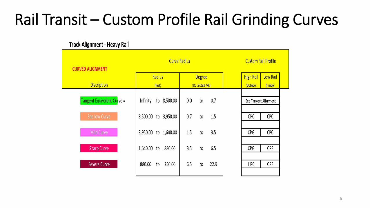
• LA Metro’s Heavy Rail System designated various Curve Radii to fall into specific categories so that the appropriate Metro Custom Rail Profile could be placed on the proper rail in a curve and depending on the radius all staff would know where such custom rail profiles were to be installed.
• Metro created a series of four (4) custom rail grinding profiles to be used throughout the rail transit system (Heavy Radius Contact – HRC, Contact Patch Gauge – CPG, Contact Patch Center – CPC, and Contact Patch Field – CPF).
5
Rail Transit – Custom Profile Rail Grinding Curves
6
Rail Transit – Custom Profile Rail Grinding Mapping
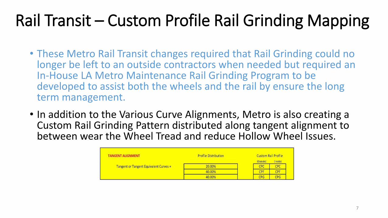
• These Metro Rail Transit changes required that Rail Grinding could no longer be left to an outside contractors when needed but required an In-House LA Metro Maintenance Rail Grinding Program to be developed to assist both the wheels and the rail by ensure the long term management.
• In addition to the Various Curve Alignments, Metro is also creating a Custom Rail Grinding Pattern distributed along tangent alignment to between wear the Wheel Tread and reduce Hollow Wheel Issues.
7

Wheel Rail Custom Rail Grinding Contact Patch
8

Basic Track Alignment Detail Info Needed
• Tangent to Spiral (TS),
• Spiral to Curve (SC)
• Curve to Spiral (CS)
• Spiral to Tangent (ST)
• Tangent to Curve (TC or PC)
• Curve to Tangent (CT or PT)
• Basis for Custom Rail Grinding is full knowledge of Construction Track Drawings or Track Charts.
• These drawings or charts must clearly identify the Actual Construction Chainage:
• Associated Curve Details Needed such as Curve Radius (R), Degree of Curve (Dc), Length of Spiral (Ls), Direction of Curve (Left or Right) moving in the direction of increasing Milepost or Chainage), and actual Length of Curve (Lc).
9

Basic Track Alignment Detail Info Needed – Cont’d
10

Basic Track Alignment Detail Info Needed – Cont’d
11
Custom Profile Rail Grinding Mapping – Track Info
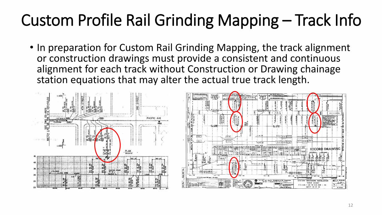
• In preparation for Custom Rail Grinding Mapping, the track alignment or construction drawings must provide a consistent and continuous alignment for each track without Construction or Drawing chainage station equations that may alter the actual true track length.
12
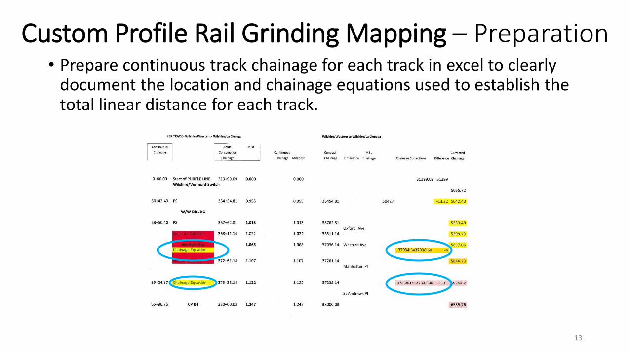
Custom Profile Rail Grinding Mapping – Preparation • Prepare continuous track chainage for each track in excel to clearly
document the location and chainage equations used to establish the total linear distance for each track.
13
Custom Profile Rail Grinding Mapping – Preparation
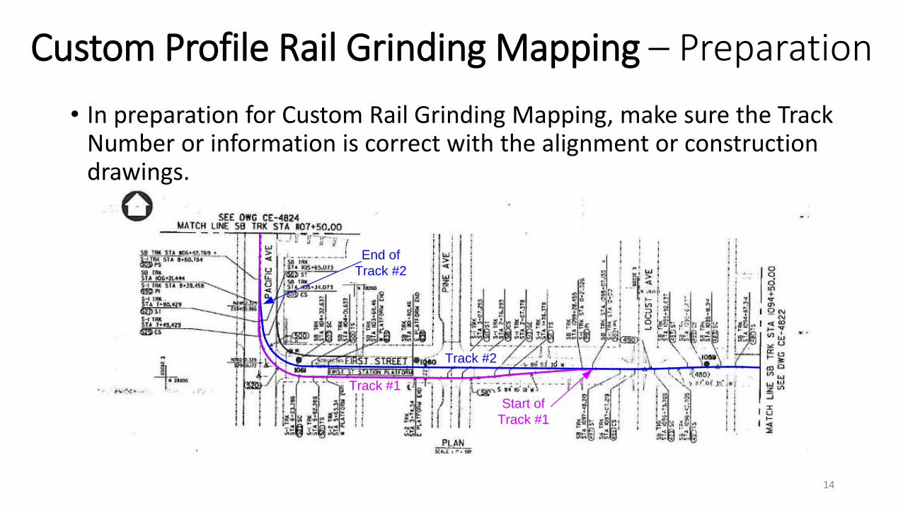
• In preparation for Custom Rail Grinding Mapping, make sure the Track Number or information is correct with the alignment or construction drawings.
14
Track #2
Track #1
End of
Track #2
Start of
Track #1
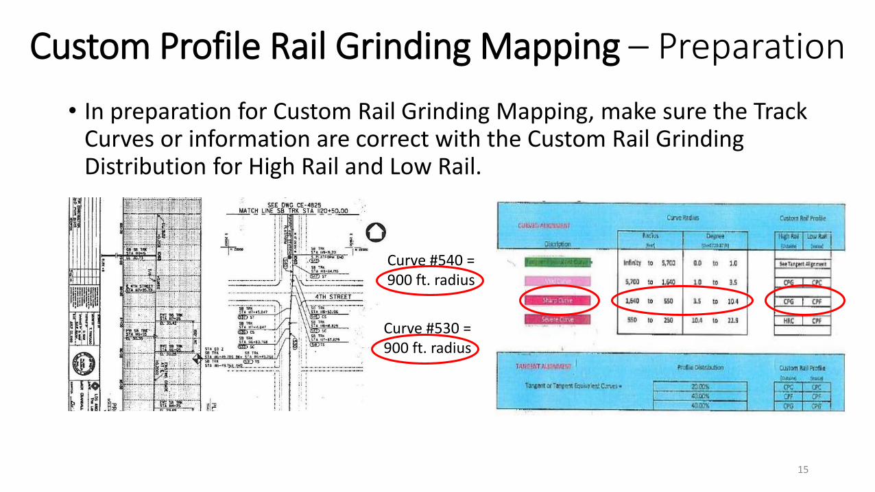
Custom Profile Rail Grinding Mapping – Preparation
• In preparation for Custom Rail Grinding Mapping, make sure the Track Curves or information are correct with the Custom Rail Grinding Distribution for High Rail and Low Rail.
15
Curve #540 =900 ft. radius
Curve #530 =900 ft. radius
Custom Profile Rail Grinding Mapping – RULES
1 Length of Rail Grinding Transition Needed: (a) LIGHT RAIL TRANSIT• The Rail Grinding Transition for a change in grinding profiles from Field (CPF)
or Gauge Profile (CPG or HRC) to the Center Profile (CPC) could be reduce to 50 feet minimum.
• For areas where Special Trackwork (Turnouts & Diamonds) are being approached or leaving then the Rail Grinding Transition for a change in grinding profiles from Field Profile (CPF) or Gauge Profile (CPG or HRC) to the Center Profile (CPC) will require the 50 feet minimum plus an additional 50 feet of Center Profile (CPC) grind before and after Special Trackwork areas.
• The Rail Grinding Transition for a change in grinding profiles from Field Profile (CPF) or Gauge Profile (CPG or HRC) to the extreme opposing profile, then the full 100 feet minimum must be provided.
16
Custom Profile Rail Grinding Mapping – RULES Cont’d
17
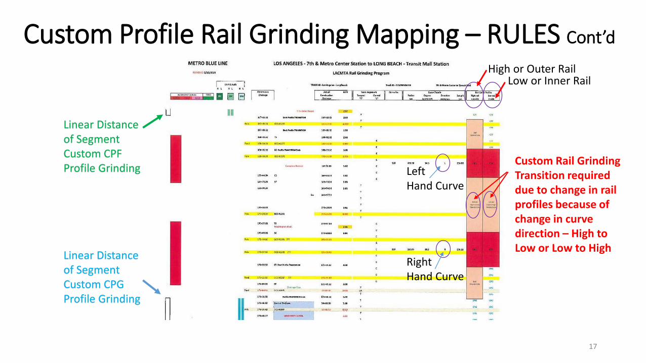
Linear Distance of Segment Custom CPF Profile Grinding
Linear Distance of Segment Custom CPG Profile Grinding
High or Outer RailLow or Inner Rail
Left Hand Curve
Right Hand Curve
Custom Rail Grinding Transition required due to change in rail profiles because of change in curve direction – High to Low or Low to High

Custom Profile Rail Grinding Mapping – RULES Cont’d
1 Length of Rail Grinding Transition Needed: (b) HEAVY RAIL TRANSIT
• The Rail Grinding Transition for a change in grinding profiles from Field (CPF) or Gauge Profile (CPG or HRC) to the Center Profile (CPC) requires 100 feet minimum.
• For areas where Special Trackwork (Turnouts & Diamonds) are being approached or leaving then the Rail Grinding Transition for a change in grinding profiles from Field Profile (CPF) or Gauge Profile (CPG or HRC) to the Center Profile (CPC) will require the 100 feet minimum plus an additional 100 feet of Center Profile (CPC) grind before and after Special Trackwork areas.
• The Rail Grinding Transition for a change in grinding profiles from Field Profile (CPF) or Gauge Profile (CPG or HRC) to the extreme opposing profile, then the full 200 feet minimum must be provided.
18

Custom Profile Rail Grinding Mapping – RULES Cont’d
19

Custom Profile Rail Grinding Mapping – RULES Cont’d
#2 Length of CPC Rail Grinding Needed: Special Trackwork• For the areas associated with switches, diamonds, turnouts or special
trackwork that must have the minimum 100 foot transition areas before and after so that the wheels are stable before traversing the special trackwork areas. Therefore the easiest way is to locate Interlocking Plant Signals or Switches and extend the areas to 200 feet before and after as the location that CPC/CPC will be required. This 200 feet includes the Actual 100 feet of Transitional Grinding to move from a CPG / HRC or CPF to CPC followed by an additional 100 feet of CPC if possible before entering the Special Trackwork Areas to allow the wheels to stabilize before traversing special trackwork. As discussed for Light Rail Transit systems, these distances can be reduced due to the Light Rail Wheels have smaller diameters and their trucks have shorter axle spacing.
20
Custom Profile Rail Grinding Mapping – RULES Cont’d
21
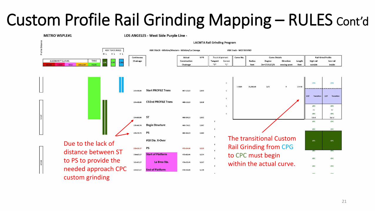
Due to the lack of distance between ST to PS to provide the needed approach CPC custom grinding
The transitional Custom Rail Grinding from CPGto CPC must begin within the actual curve.
Custom Profile Rail Grinding Mapping – RULES Cont’d
#3 Continuous Distances Needed:
• Ensure all construction equations are included and the track distances for both tracks in double track territory can be related accurately from common points (Chainage Markers, Mileposts Markers, or Fixed Facilities) such as stations; curve indicators (TS, SC, CS, ST, PT, PC or TC, CT); interlocking plants; or street crossings so accurate distances can be determined.
22
Custom Profile Rail Grinding Mapping – RULES Cont’d
#4 Identify Beginning and End of Curves Needed: Track Chart Info• Continuous Distances so that all construction equations are included
and the track distances for both tracks in double track territory can be related accurately from common points (Chainage Markers, Mileposts Markers, or Fixed Facilities) such as stations; curve indicators (TS, SC, CS, ST, PT, PC or TC, CT); interlocking plants; or street crossings so accurate distances can be determined.
23

Custom Profile Rail Grinding Mapping – RULES Cont’d
24

Custom Profile Rail Grinding Mapping – RULES Cont’d
#5 Identify Associated Curve Spiral Lengths Needed: Track Chart Info• Know the amount of length each curve will have to allow the Custom Rail
Grinding Transitions. This is important so that the final mapping will be adjusted to have sufficient distances to complete the change in Custom Rail Grinding Profiles:
• 100 foot transition for a Gauge (CPG) or Heavy (HRC) Custom Profile to a Center (CPC) Custom Profile or for a Field (CPF) Custom Profile to a Center (CPC) Custom Profile etc.
• 200 foot transition for a Gauge (CPG) or Heavy (HRC) Custom Profile to a Field (CPF) Custom Profile etc.
• If insufficient spiral length, start transition at the SC or CS so that the proper custom profiles are through the actual curve and extend the transition outward.
25

Custom Profile Rail Grinding Mapping – RULES Cont’d
#6 Prepare Custom Rail Grinding Mapping: Each Track• See typical Mapping Document development with Curve Radii, Spiral
Lengths, and continuous Chainage or Mileposts below for references:
26
Custom Profile Rail Grinding Mapping – RULES Cont’d
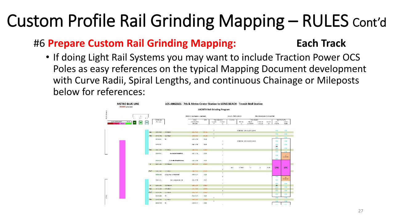
#6 Prepare Custom Rail Grinding Mapping: Each Track• If doing Light Rail Systems you may want to include Traction Power OCS
Poles as easy references on the typical Mapping Document development with Curve Radii, Spiral Lengths, and continuous Chainage or Mileposts below for references:
27

Custom Profile Rail Grinding Mapping – RULES Cont’d
#7 Determine Linear Distance of Tangent or Tangent Equivalent Curves: • Determine what portion of the alignment for EACH TRACK is tangent
or has curves that are classified as tangent equivalent less special trackwork areas and develop the total Mapping Document supports the relative distribution of CPG / CPG, CPC / CPC, CPF / CPF development so the split is 40%, 20%, 40% as inferred by the Profile Distribution requirements:
28

Custom Profile Rail Grinding Mapping – RULES Cont’d
#8 Determine if additional Custom Rail Grinding Transitions needed:• If the Profile Distribution for each track is not split correctly then some of
the long tangent / tangent equivalent sections may be required to be split to better provide the desired profile split and gain the uniformity of wheel wear and reduce wheel hollowing.
29
Custom Profile Rail Grinding Mapping – RULES Cont’d
#9 Prepare Initial Custom Rail Grinding Mapping for One Track:
• By adding up the Various Distributions of the Custom rail Grinding Profiles by track not including the specialized Custom CURVE Areas, Specialized Transition Areas associated with each Curve and support around Special Trackwork Areas, and any added Tangent or tangent Equivalent Profile changes to better obtain the overall distribution.
• When this is reporting numbers are reviewed then a realistic redistribution of the Custom Rail Grinding Profiles along the tangent or tangent equivalent areas may be required.
30

Custom Profile Rail Grinding Mapping – RULES Cont’d
#9 Prepare Initial Custom Rail Grinding Mapping for One Track:
31
Custom Profile Rail Grinding Mapping – RULES Cont’d
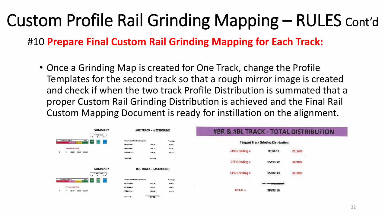
#10 Prepare Final Custom Rail Grinding Mapping for Each Track:
• Once a Grinding Map is created for One Track, change the Profile Templates for the second track so that a rough mirror image is created and check if when the two track Profile Distribution is summated that a proper Custom Rail Grinding Distribution is achieved and the Final Rail Custom Mapping Document is ready for instillation on the alignment.
32
Custom Profile Rail Grinding Mapping
This completes a Basic Overview of how to prepare the Custom Rail Profile Grinding Maps for a rail transit property:
▪ It is needed to properly apply and document the locations where each change in Custom Rail Grinding Templates will occur and
▪ It allows for minimum effort if and when touch-up rail grinding is required to remove defects or minor adjustments in surface of your running rails
33