effective november 2011 technical data td00801003e ...electrical/documents/content/td00801… · 3...
TRANSCRIPT
ContentsDescription Page
Danger and Warnings . . . . . . . . . . . . . . . . . . . . . . 2Overview, Standard & Optional Features . . . . . . .3Catalog Number System . . . . . . . . . . . . . . . . . . . . 3Other Options . . . . . . . . . . . . . . . . . . . . . . . . . . . . 4Shunt-Trip Operation . . . . . . . . . . . . . . . . . . . . . . . 4Transformer Fuse Table . . . . . . . . . . . . . . . . . . . . . 4Lug Torque Specifications . . . . . . . . . . . . . . . . . . . 4Wiring Options . . . . . . . . . . . . . . . . . . . . . . . . . . . 5Voltage Monitoring with “B-Contact” Option . . . 11Maintenance . . . . . . . . . . . . . . . . . . . . . . . . . . . . 13FAQs . . . . . . . . . . . . . . . . . . . . . . . . . . . . . . . . . . 13For more information, visit eaton .com
Effective November 2011Supercedes December 2009Technical Data TD00801003E
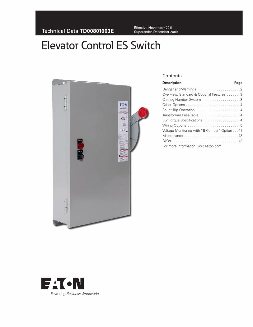
Elevator Control ES Switch

2
Technical Data TD00801003EEffective November 2011
Elevator Control ES Switch
eaton corporation www.eaton.com
Danger and Warnings
DangerHazarDous Voltage Will cause seVere injury or DeatH. Working on or near energizeD circuits poses a serious risk of electrical sHock. De-energize all circuits before installing or serVicing tHis equipment anD folloW all prescribeD safety proceDures.
importanttHese proceDures Do not claim to coVer all possible Details or Variations encountereD WitH tHe eleVator control sWitcH ele-Vator Disconnect. nor Do tHey proViDe for all possible conDi-tions tHat may be encountereD. if furtHer information is DesireD or neeDeD to aDDress any particular issue not coVereD in tHis Document, contact your eaton representatiVe. tHe information in tHis Document Does not relieVe tHe user from exercising gooD juDgment, nor from using sounD safety prac-tices. note: because eaton Has a policy of continuous proDuct improVement, We reserVe tHe rigHt to cHange Design specifica-tions WitHout notice. sHoulD a conflict arise betWeen tHe gen-eral information in tHis Document anD tHe contents of DraW-ings or supplementary material, or botH, tHe latter sHall take preceDence. for tHe latest Version of tHis instruction leaflet, DoWnloaD tD00801003e from tHe eaton Web site at: www.eaton.com.
tHe contents of tHis instruction leaflet are not part of, nor Do tHey moDify, any prior or existing agreement, commitment or relationsHip. tHe eaton terms anD conDitions of sale con-stitute tHe entire obligation of eaton. tHe Warranty in tHe terms anD conDitions of sale is tHe sole Warranty of eaton. any statements in tHis Document Do not create neW Warran-ties or moDify any existing Warranty.
importantfor tHe purpose of tHis instruction leaflet, a qualifieD person:
(a) is familiar WitH tHe subject equipment anD tHe HazarDs inVolVeD WitH tHeir application, use, aDministration, anD maintenance.
(b) is traineD anD autHorizeD to De-energize, clear, grounD, anD tag circuits anD equipment in accorDance WitH establisHeD safety practices.
(c) is traineD in tHe proper care anD use of personal protectiVe equipment sucH as rubber gloVes, HarD Hat, safety glasses or face sHielDs, arc-flasH clotHing, etc., in accorDance WitH establisHeD safety practices.
(D) is traineD to renDer first aiD.
(e) Has receiVeD safety training to recognize anD aVoiD tHe HazarDs inVolVeD.
(f) as tHe skills anD knoWleDge pertaining to tHe construction anD operation of tHis equipment anD its installation.
Signal Words
The signal words “DANGER,” “WARNING,” “CAUTION” and “NOTICE” (along with their assigned symbol) throughout this manu-al indicate the degree of hazard the user may encounter .
These symbols and words are defined as:
Danger
DANGER: Indicates a hazardous situation which, if not avoided, will result in death or serious injury .
Warning
WARNING: Indicates a hazardous situation which, if not avoided, could result in death or serious injury .
caution
CAUTION: Indicates a hazardous situation which, if not avoided, could result in minor or moderate injury .
notice
NOTICE: Indicates a hazardous situation which, if not avoided, could result in property damage .
Safety Concerns
The following are important safety precautions that Elevator Control Switch elevator disconnect users should observe at all times . This summary is not comprehensive . It is assumed the Elevator Control Switch elevator disconnect user will follow standard safety precau-tions for working in an electrical environment . For more information on safety precautions and procedures, consult the following sources:
Web Sites:
National Fire Protection Association (NFPA): www .nfpa .org .
Underwriters Laboratories (UL): www .ul .com .
National Electrical Manufacturers Association (NEMA): www .nema .org .
International Electrotechnical Commission (IEC): www .iec .ch .

3
Technical Data TD00801003EEffective November 2011
Elevator Control ES Switch
eaton corporation www.eaton.com
OverviewThe Eaton Elevator Control ES disconnect switch is designed for single cable or hydraulic elevator application to interrupt the incoming AC power upon receiving a signal from the Fire Alarm Control Panel (FACP) .
The Elevator Control Switch numbering system assures you get all the right components, with the right ratings, and properly assembled . The unit comes completely assembled for quick instal-lation, eliminating the labor and time needed to assemble individual components . It is also easy to meet Code requirements for selec-tive coordination in a fully fused system . The Eaton Elevator Control ES Switch utilizes Class J fuses that easily coordinate with any upstream fuse by simply using a 2:1 lineside-to-loadside fuse ratio .
The Eaton Elevator Control ES Switch meets prevailing ANSI/ASME, NEC® and NFPA 72 requirements in a UL 98 Listed (enclosed switch) and UL 50 Listed (enclosure) unit . It comes in a standard NEMA 1 enclosure or optional NEMA 3R, 4, or 12 enclosures . It is available in 30, 60, 100, 200 or 400 amp configurations, for 208, 240, 480, or 600 Vac, 3 or 4 wire systems with a UL 98 Listed 200kA assembly short-circuit current rating (SCCR) .
Standard Features• 30-400 amp 600 Vac 3-phase fused power switch• 200 kA RMS assembly short-circuit current rating• Shunt trip 120 V• Control power terminal block• Ground lug per NECT
• Class J fuse mounting only (Class J fuses not included)
• Key to test switch• Pilot light – “ON”• Mechanically interlocked auxiliary contact for hydraulic elevators
with battery backup (5 amp 120 Vac rated)
Optional Features• Control power transformer with fuses and blocks• Fire safety interface relay• Isolated neutral lug (oversized 200% rated neutral option available
where required by excessive non-linear loads)• Fire Alarm Voltage Monitoring Relay (to monitor Shunt Trip Voltage)• NEMA 3R, 4, and 12 enclosures available
Agency Information• UL 98 Enclosed and Dead Front Switch - Guide 96NK3917, File
E182262• NEMA 1, UL 50, listed enclosure cUL per Canadian Standards
C22 .1• CAN/CSA C22 .2, No . 4 Enclosed Switch
Catalog Number SystemThe following catalog numbering system defines an Elevator Control Switch construction .
100 VA with Primary and Secondary fusing (120 V Secondary)
Figure 1. Eaton Elevator Control Switch Selector.
Prefix
ES = Elevator Control Switch
AmpereRating
1 = 30 A2 = 60 A3 = 100 A4 = 200 A
Control Transformer
T2 = 208 VoltT3 = 240 VoltT1 = 480 VoltT4 = 600 Volt
Fire Safety Interface Relay (3PDT, 10 A, 120 V)
R2 = 24 Vdc CoilR1 = 120 Vac Coil
Pilot Light ON
G = GreenR = RedW = White
Fire Alarm Voltage Monitoring Relay
(To Monitor ShuntTrip Voltage)
F1 = Single-PoleF3 = Three-Pole
Enclosure Options (NEMA 1 Standard With No Suffix Designation Required)
3 = NEMA 3RD = NEMA 12P = NEMA 4 Painted Steel
ES 1 T2 R2 G F1 3 N B
Neutral Lug
N = IsolatedFull Capacity
Auxiliary Contacts1NO/1NC
B = Main Switch
4
Technical Data TD00801003EEffective November 2011
Elevator Control ES Switch
eaton corporation www.eaton.com
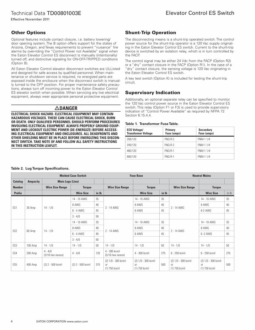
Other OptionsOptional features include contact closure, i .e . battery lowering/door opening system . The B option offers support for the states of Arizona, Oregon, and Texas requirements to prevent “nuisance” fire alarms by over-riding the “Control Power not Available” signal when the Eaton Elevator Control ES disconnect is manually (intentionally) turned off, and distinctive signaling for ON-OFF-TRIPPED conditions (Option B) .
All Eaton Elevator Control elevator disconnect switches are UL-Listed and designed for safe access by qualified personnel . When main-tenance or shutdown service is required, no energized parts are exposed inside the enclosure when the disconnect switch is manual-ly turned to the OFF position . For proper maintenance safety precau-tions, always turn off incoming power to the Eaton Elevator Control ES elevator switch when possible . When servicing any live electrical equipment, always wear appropriate personal protective equipment .
Dangerelectrical sHock HazarD. electrical equipment may contain HazarDous Voltages. tHese can cause electrical sHock, burn or DeatH. only qualifieD personnel sHoulD perform proceDures inVolVing electrical equipment. alWays properly grounD equip-ment anD lockout electric poWer (De-energize) before access-ing electrical equipment anD enclosures. all DeaDfronts anD otHer sHielDing must be in place before energizing tHis Discon-nect sWitcH. take note of anD folloW all safety instructions in tHis instruction leaflet.
Shunt-Trip OperationThe disconnecting means is a shunt-trip operated switch . The control power source for the shunt-trip operator is a 120 Vac supply originat-ing in the Eaton Elevator Control ES switch . Current to the shunt-trip device is switched by an isolation relay, which is in turn controlled by the FACP .
The control signal may be either 24 Vdc from the FACP (Option R2) or a “dry” contact closure in the FACP (Option R1) . In the case of a “dry” contact closure, the sensing voltage is 120 Vac originating in the Eaton Elevator Control ES switch .
A key test switch (Option K) is included for testing the shunt-trip circuit .
Supervisory IndicationAdditionally, an optional separate relay can be specified to monitor the 120 Vac control power source in the Eaton Elevator Control ES switch . This relay (Option F1 or F3) is used to provide supervisory indication of “Control Power Available” as required by NFPA 72 Section 6 .15 .4 .4 .
Table 1. Transformer Fuse Table.
ecs Voltage/transformer Voltage
primary fuse (amps)
secondary fuse (amps)
208/120 FNQ-R-2 FNM-1 1/4
240/120 FNQ-R-2 FNM-1 1/4
480/120 FNQ-R-1 FNM-1 1/4
600/120 FNQ-R-1 FNM-1 1/4
Table 2. Lug Torque Specifications.
molded case switch fuse base neutral mains
catalog ampacity main lugs (line)
number Wire size range torque Wire size range torque Wire size range torque
prefix Wire size in lb Wire size in lb Wire size in lb
ES1 30 Amp 14 - 1/0
14 - 10 AWG 35
2 - 14 AWG
14 - 10 AWG 35
2 - 14 AWG
14 - 10 AWG 35
8 AWG 40 8 AWG 40 8 AWG 40
6 - 4 AWG 45 6 AWG 45 6-2 AWG 45
3 - 4/0 50
ES2 60 Amp 14 - 1/0
14 - 10 AWG 35
2 - 14 AWG
14 - 10 AWG 35
2 - 14 AWG
14 - 10 AWG 35
8 AWG 40 8 AWG 40 8 AWG 40
6 - 4 AWG 45 6 AWG 45 6 -2 AWG 45
3 - 4/0 50
ES3 100 Amp 14 - 1/0 14 - 1/0 50 14 - 1/0 14 - 1/0 50 14 - 1/0 14 - 1/0 50
ES4 200 Amp 4 - 4/0 (3/16 hex recess) 4 - 4/0 120 4 - 300 kcmil
(5/16 hex recess) 4 - 300 kcmil 275 6 - 250 kcmil 6 - 250 kcmil 275
ES5 400 Amp (2) 2 - 500 kcmil (2) 2 - 500 kcmil 375(2) 1/0 - 300 kcmil or (1) 750 kcmil
(2) 1/0 - 300 kcmil or (1) 750 kcmil
500(2) 1/0 - 300 kcmil or (1) 750 kcmil
(2) 1/0 - 300 kcmil or (1) 750 kcmil
500

5
Technical Data TD00801003EEffective November 2011
Elevator Control ES Switch
eaton corporation www.eaton.com
Typical Control with Wiring Options for Fire Safety Interface
Figure 2. Options R1 and F3.
auxiliary switch logic
main switch position
option a option b option a *
no nc no nc no nc
Closed O C O C O C
Tripped C C O C C O
Open C O C O C O
* Auxiliary Switch Logic when blue wire with “+” marker is removed from NC terminal.
Where local authorities having jurisdiction permit, field removal of the blue wire identified by “+” marker will change the option A switch logic. Removal has the effect of disabling the bat-tery lowering device when the switch is in the tripped position. Field installer must ensure this meets all local codes before removal.
OPTIONS R1 & F3 TYPICAL CONTROL WITH WIRING OPTIONS FOR FIRE SAFETY INTERFACE

6
Technical Data TD00801003EEffective November 2011
Elevator Control ES Switch
eaton corporation www.eaton.com
Typical Control with Wiring Options for Fire Safety Interface (Cont.)
Figure 3. Option R2

7
Technical Data TD00801003EEffective November 2011
Elevator Control ES Switch
eaton corporation www.eaton.com
Typical Control with Wiring Options for Fire Safety Interface (Cont.)
Figure 4. Options R1 and F1

8
Technical Data TD00801003EEffective November 2011
Elevator Control ES Switch
eaton corporation www.eaton.com
Typical Control with Wiring Options for Fire Safety Interface (Cont.)
Figure 5. Options R2 and F1
WHERE LOCAL ANTHORITIES HAVING JURISDICTION PERMIT, FIELD REMOVAL OF THE BLUE WIRE IDENTIFIED BY *+* MARKER WILL CHANGE THE OPTION A SWITCH LOGIC, SEE THE AUXILARY SWITCH LOGIC TABLE, REMOVAL HAS THE EFFECTOF DISABLING THE BATTERY LOWERING DEVICEWHEN THE SWITCH IS IN THE TRIPPED POSITION. FIELD INSTALLER MUST ENSURE THIS MEETS ALLLOCAL CODES BEFORE REMOVAL.
OPTION R2 & F1
9
Technical Data TD00801003EEffective November 2011
Elevator Control ES Switch
eaton corporation www.eaton.com
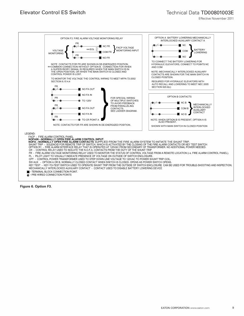
Figure 6. Option F3.

10
Technical Data TD00801003EEffective November 2011
Elevator Control ES Switch
eaton corporation www.eaton.com
Figure 7. Option F1
11
Technical Data TD00801003EEffective November 2011
Elevator Control ES Switch
eaton corporation www.eaton.com
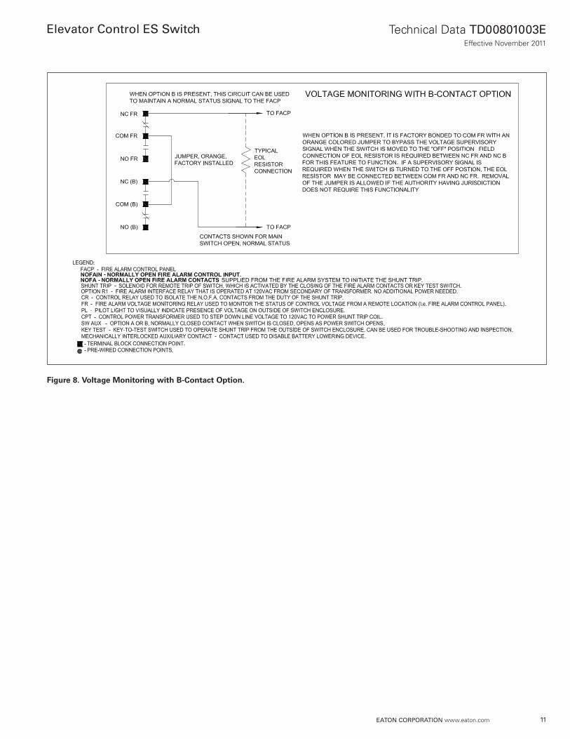
Figure 8. Voltage Monitoring with B-Contact Option.

12
Technical Data TD00801003EEffective November 2011
Elevator Control ES Switch
eaton corporation www.eaton.com
Figure 9. Common Wiring Scheme for AZ, TX, and OR Applications. Elevator Control Option B Detail.

13
Technical Data TD00801003EEffective November 2011
Elevator Control ES Switch
eaton corporation www.eaton.com
Dangerelectrical sHock HazarD. electrical equipment may contain HazarDous Voltages. tHese can cause electrical sHock, burn or DeatH. only qualifieD personnel sHoulD perform proceDures inVolVing electrical equipment. alWays properly grounD equip-ment anD lockout electric poWer (De-energize) before access-ing electrical equipment anD enclosures. all DeaDfronts anD otHer sHielDing must be in place before energizing tHis Discon-nect sWitcH. take note of anD folloW all safety instructions in tHis instruction leaflet.
MaintenanceTo properly maintain the Eaton Elevator Control ES Switch, the operation of all components should be tested on an annual basis by a qualified person .• Take the necessary precautions to notify the occupants of the
building that the elevator is under maintenance and has been taken out of service .
• Verify that power is on .
• Activate the Fire Alarm system contacts for the shunt trip .
Note: A Fire Alarm Technician may be required to exercise this step . If a key test switch is included with the Elevator Control ES switch, it can be used to shunt trip the unit without the Fire Alarm system .
• This will energize the Fire Alarm Isolation Relay and close relay contact points 4 and 7 .
• The closure of points 4 and 7 will energize the shunt trip coil, open the contacts of the switch, and place the switch and handle into the “TRIP” position .
• Verify that power has been disconnected and the handle is in the “TRIP” position .
• Pull to the “RESET” position and allow handle to go to the “OFF” position .
• Push to the “ON” position .
• Verify that power has been restored .
• The above sequence verifies that the contents of the Eaton Elevator Control ES Switch are operating properly . If the above sequence is unable to be completed, please contact Eaton .
Preventative Maintenance Measures
• Periodically check lug torque values and keep them in specifica-tion .
• An annual review of the Eaton Elevator Control ES Switch is rec-ommended . Preventative maintenance should include a thermal-scan to uncover any portion generating excessive heat that indi-cates an underlying problem .
• Any unexpected temperature increase, not related to load varia-tions or ambient temperature could signal a lug torque issue .
• Maximum temperature at any lug should never exceed 75°C under any operating condition or load .
• Keep switch exterior and interior clean . Always follow prevailing safety rules when servicing this product throughout the year .
Frequently Asked QuestionsFor more information or if you have additional questions, please con-tact EatonCare . 877-ETN-CARE (877-386-2273) .
1. What UL-Listings and Agency Standards does the Eaton Elevator Control ES have?
• NFPA-70 (NECT) 2008 Edition- Section 620 .51(A)-(C), 620 .62, 620 .91(C)
• Canadian Electric Code Part 1 (2006 Edition) Section 38-051, 38-062
• ANSI/ASME A17 .1-2007 - Section 2 .8 .3 .3 .2 NFPA-72 2007 Edition - Section 6 .16 .4 .4
All work shall be performed in accordance with the latest edition of applicable standards, codes, and laws .
2. What kind of fuses does Eaton recommend?
LPJ_SP or LPJ_SPI (indication version) dual-element, time-delay Class J fuses . The panel’s holders only accept this class of fuse . The fuses are current limiting for good short-circuit and motor overload protection, and minimizing are flash hazards . For general fuse siz-ing the NECT Article 430 .52 allows sizing time-delay fuses used in motor branch circuits to be sized for up to 175% of the motor full load amps .
3. How does the Mechanical Auxiliary Contact Option (Option A) work?
The “A” Option is a set of auxiliary contacts that are mechanically interlocked to the main switch . The contacts are used to enable or disable the Battery Lowering Device (BLD) for maintenance per NFPA code . It is important to note that these contacts can differ-entiate between manually turned OFF or shunted OFF (see table below) . The most common contact is the “NC,” normally closed .
Table 3.
auxiliary switch logic
main switch position
option a option b option a *
no nc no nc no nc
Closed O C O C O C
Tripped C C O C C O
Open C O C O C O
* Auxiliary Switch Logic when blue wire with “+” marker is removed from NC terminal.
4. How does the Mechanical Auxiliary Contact Option (Option B) work?
The “B” Option provides a second set of auxiliary contacts that are mechanically interlocked to the main switch . These contacts are generally used to monitor the status of the switch . It is important to note that these contacts will follow the state of the external handle (see table below and Figure 5) .
Table 4.
main switch
contact state facp
no nc ncfr/ncb
OFF, Power Avail Open Closed Open
ON, Power Avail Closed Open Open
OFF, No Power Open Closed Open
ON, No Power Closed Open Closed

14
Technical Data TD00801003EEffective November 2011
Elevator Control ES Switch
eaton corporation www.eaton.com
5. How does the Special Wiring Option for maintaining Normal Status Signal to the FACP work?
For Arizona and other areas requiring this feature, internal wiring between the molded case switch’s auxiliary contacts and the fire relay’s contacts implements a logic circuit that monitors the availability of shunt-trip power . The FR relay closes only if the main switch is ON and the shunt-trip power fails . They will not close if the main switch is manually turned OFF for maintenance, the Series B contact will open, thus preventing a false alarm . (Refer to Table 4 and Figure 5) .
6. Does the instantaneous trip feature built into the molded case switch create the potential to strand passengers when used on circuits with hydraulic elevators and auxil-iary battery lowering?
No, the Battery Lowering Device (BLD) remains operational under a shunt-trip condition . The shunt-trip mechanism within the switch is utilized, not the instantaneous trip feature of the switch . The proper fuse selection will prevent instantaneous trip . Even in the event of an instantaneous trip condition, the alarm relay will respond the same as when the switch is shunted off . There is no potential for stranding passengers when units are installed with the Mechanical Interlock Auxiliary Contact Option (Option A, battery back-up feature) .
7. During a power loss, will the state of the switch change state (F1 or F3 option)?
The Eaton Elevator Control ES switch will not change state . The Eaton Elevator Control ES Voltage Monitoring Relay (F1 or F3 Option) does meet NFPA 72 (National Fire Alarm Code) requiring control circuits to be monitored for presence of voltage . The unit is wired to sense the voltage available to initiate the shunt-trip . It will change state if a power loss occurs . It does not rely on the shunt-trip itself . It will send a signal to the FACP upon power loss .
8. How does the Eaton Elevator Control ES switch decide when the elevator needs to be lowered?
The Eaton Elevator Control ES switch does not make that deci-sion . It provides a signaling means to the fire alarm controller and BLD . The Elevator Control switch receives a signal from the FACP to shunt-trip, which in some cases results in the use of the Battery Lowering Device (BLD) .
9. Does the Eaton Elevator Control ES switch require any periodic maintenance?
While no specific maintenance is called for, it is always a good prac-tice to annually inspect the unit for any lose fuse clips or connec-tions, or accumulation of foreign material . See “Maintenance” in this document for more details .
10. How do you hook up the dry contacts for the battery back-up (BLD) option?
This will depend on how the Mechanical Auxiliary Contact (Option A) will be connected . The A Option will follow the truth table noted below . The most common connection will be between NC and COM .
Table 5.
auxiliary switch logic
main switch position
option a option b option a *
no nc no nc no nc
Closed O C O C O C
Tripped C C O C C O
Open C O C O C O
* Auxiliary Switch Logic when blue wire with “+” marker is removed from NC terminal.
Where local authorities having jurisdiction permit, field removal of the blue wire identified by “+” marker will change the Option A switch logic . Removal has the effect of disabling the battery lowering device when the switch is in the tripped position . Field installer must ensure this meets all local codes before removal .
11. Where do you land the shunt-trip control wires on the terminal strip?
For the R1 Option (120Vac), land the wires on Terminals 1 and 3 or NOFAIN and NOFAIN (Normally Open Fire Alarm IN) . For the R2 (24Vdc) option, land the positive on Terminal 1 and the closure on Terminal 3, with the return on Terminal 7 .
12. Where does the fire alarm get connected for monitoring the status of the switch?
This is commonly referred to as the FR relay and is Option F1 or F3 . NCFR/COM FR is the most common . If an end of line (EOL) resistor is used, install it parallel to the wires .
13. If an Eaton Elevator Control ES switch is ordered with a wrong component, can the component be changed in the field?
No . To comply with UL guidelines, product modifications can only be completed by authorized factory personnel . Other modifications will void the Eaton UL listing . One exception is the B-option . It can be ordered and field installed; the part number is ECSBKIT .
14. Can the Eaton Elevator Control ES switch be used as a service entrance switch?
The Eaton Elevator Control ES switch is UL-Listed per UL 98 . Yes, it can be used as a service entrance if properly labeled as such and proper ground bond requirements are met .
15. Can the Eaton Elevator Control ES switch be fed in reverse with the line from the bottom and load out the top of the switch?
No, the Eaton Elevator Control ES switch will not properly function .

15
Technical Data TD00801003EEffective November 2011
Elevator Control ES Switch
eaton corporation www.eaton.com
16. Can the Eaton Elevator Control ES switch be used in an application where no fire alarm exists and can a smoke detector be connected instead?
No, this is not in accordance with the fire code . Commercial smoke detectors must be connected through the FACP .
17. Does the FR Relay (Option F1 or F3) change state during a power loss?
Yes, the FR relay will change state . The FR relay is designed to moni-tor voltage that is available for the shunt-trip . This is a requirement of NFPA 72 .
18. Is the operating handle of the Eaton Elevator Control ES switch lockable in the “OFF” position only?
From the factory the handle can only be locked in the “OFF” position and can accommodate a maximum of three padlocks . Field modifica-tion to drill the shroud can allow locking in the “ON” position . Check with your local AHJ for requirements . The switch will shunt trip as usual, even with the handle locked ON .
19. What enclosures are available for the Eaton Elevator Control ES Switch?
All ratings of the Eaton Elevator Control ES switch come standard with a UL (NEMA) Type 1 enclosure . Optional enclosures include UL (NEMA) type 3R, 4, and 12 . Consult the factory for other options .
20. Is a CPT always required in an Eaton Elevator Control ES switch?
Yes, to meet NFPA codes, a CPT will be required to supply the 120Vac for shunt-tripping .
21. I lost the keyswitch, can I get another?
Yes . The part number is E22KS2 if the back of the switch says E22 . If the back of the switch says M22, the part number is M22-ES-MS1 .
Technical Data TD00801003EEffective November 2011
Elevator Control ES Switch
Eaton CorporationElectrical Group1000 Cherrington ParkwayMoon Township, PA 15108United States877-ETN-CARE (877-386-2273)Eaton.com
© 2011 Eaton CorporationAll Rights ReservedPrinted in USAPublication No. TD00801003E TBG000266November 2011
Eaton is a registered trademark of Eaton Corporation.
All other trademarks are property of their respective owners.
These technical data materials are published solely for information purposes and should not be considered all-inclusive . If further infor-mation is required, you should consult an authorized Eaton sales representative .
The sale of the product shown in this literature is subject to the terms and conditions outlined in appropriate Eaton selling policies or other contractual agreement between the parties . This literature is not intended to and does not enlarge or add to any such contract . The sole source governing the rights and remedies of any purchaser of this equipment is the contract between the purchaser and Eaton .
NO WARRANTIES, EXPRESSED OR IMPLIED, INCLUDING WARRANTIES OF FITNESS FOR A PARTICULAR PURPOSE OR MERCHANTABILITY, OR WARRANTIES ARISING FROM COURSE OF DEALING OR USAGE OF TRADE, ARE MADE REGARDING THE INFORMATION, RECOMMENDATIONS, AND DESCRIPTIONS CONTAINED HEREIN . In no event will Eaton be responsible to the purchaser or user in contract, in tort (including negligence), strict liability or otherwise for any special, indirect, incidental or conse-quential damage or loss whatsoever, including but not limited to damage or loss of use of equipment, plant or power system, cost of capital, loss of power, additional expenses in the use of existing power facilities, or claims against the purchaser or user by its cus-tomers resulting from the use of the information, recommendations and description contained herein .