effective normal stress alteration due to pore pressure...
TRANSCRIPT

Effective normal stress alteration due to pore
pressure changes induced by dynamic slip
propagation on a plane between dissimilar materials
John W. Rudnicki1 and James R. Rice2
Received 16 March 2006; accepted 11 July 2006; published 28 October 2006.
[1] Recent, detailed examinations of fault zones show that walls of faults are oftenbordered by materials that are different from each other and from the more uniformmaterial farther away. In addition, they show that the ultracataclastic core of mature faultzones, where slip is concentrated, is less permeable to flow across it than the adjoiningmaterial of the damage zone. Inhomogeneous slip at the interface between materialswith different poroelastic properties and permeabilities causes a change in pore pressurethere. Because slip causes compression on one side of the fault wall and extension on theother, the pore pressure on the fault increases substantially when the compressed side issignificantly more permeable and decreases when, instead, the extended side is morepermeable. This change in pore pressure alters the effective normal stress on the slip planein a way that is analogous to the normal stress alteration in sliding between elasticallydissimilar solids. The magnitude of the effect due to induced pore pressure can becomparable to or larger than that induced by sliding between elastic solids with adissimilarity of properties consistent with seismic observations. The induced porepressure effect is increased by increasing contrast in permeability, but the normal stressalteration due to elastic contrast increases rapidly as the rupture velocity approaches thegeneralized Rayleigh velocity. Because the alteration in effective normal stress due toeither effect can be positive or negative, depending on the contrast in properties, the twoeffects can augment or offset each other.
Citation: Rudnicki, J. W., and J. R. Rice (2006), Effective normal stress alteration due to pore pressure changes induced by dynamic
slip propagation on a plane between dissimilar materials, J. Geophys. Res., 111, B10308, doi:10.1029/2006JB004396.
1. Introduction
[2] A number of recent field studies [Chester et al., 1993;Chester and Chester, 1998; Lockner et al., 2000; Wibberleyand Shimamoto, 2003; Sulem et al., 2004; Noda andShimamoto, 2005] have identified the ultracataclastic coresof mature fault zones, where the slip is concentrated, andshown that the core is much less permeable to flow across itthan is the adjoining material of the damage zone. Becauseslip causes compression on one side of the fault wall andextension on the other, the pore pressure tends to increaseon the compressive side and decrease on the extensile. Thisstrong gradient results in a pore pressure on the fault slipsurface (treated as a plane) that depends on the difference inproperties on the two sides. The pore pressure on the faultincreases substantially when the compressed side is signif-icantly more permeable, and decreases when, instead, the
extended side is more permeable. An increase in porepressure reduces the effective compressive stress and hencethe frictional resistance to slip, whereas a decrease has theopposite effect. Rudnicki and Koutsibelas [1991] consideredthe case of identical properties on the two sides of acompletely impermeable fault plane. Following a sugges-tion of J. R. Rice (personal communication, 1987), theyargued that the pore pressure increase, rather than thedecrease on the other side of the slip zone, affects the rupturepropagation. Their interpretation emerges as the proper limitcase here when there is a much more permeable material onthe compressive side than on the extensile.[3] This paper calculates the pore pressure induced by a
dynamically propagating fault within the framework of themodel used by Rice et al. [2005] (hereinafter referred to asRSP). The calculation is based on a model of discontinuousslip on a plane in an otherwise homogeneous poroelasticsolid, but, in calculating the pore pressure change, weinclude the effects of differences in material properties innarrow damage and granulation zones along the fault walls.The pore pressure discontinuity predicted to occur across acompletely impermeable slip plane idealizes the spatiallyrapid pore pressure variation that would occur across anarrow but finite width fault zone with, generally, differentproperties than the surrounding material (Figure 1). The
JOURNAL OF GEOPHYSICAL RESEARCH, VOL. 111, B10308, doi:10.1029/2006JB004396, 2006ClickHere
for
FullArticle
1Department of Mechanical Engineering and Department of Civil andEnvironmental Engineering, Northwestern University, Evanston, Illinois,USA.
2Department of Earth and Planetary Sciences and Division ofEngineering and Applied Sciences, Harvard University, Cambridge,Massachusetts, USA.
Copyright 2006 by the American Geophysical Union.0148-0227/06/2006JB004396$09.00
B10308 1 of 18

model treated in the main part of the paper considers thematerial on the two sides of the fault as homogeneous andsimply assumes, as in the work by Rudnicki and Koutsibelas[1991], that the pore pressure on the compressive sidecontrols strength. We show, however, in Appendix B thata more elaborate model of the near fault region can beincluded simply by modifying the coefficient of the porepressure (Skempton’s coefficient) in the main text.[4] In the more elaborate model (Figure 1, inset), the
permeability and poroelastic properties of the material onthe two sides of the fault differ from each other and from thehomogeneous material farther from the fault. This model isconsistent with fault zone studies that show that the faultcore is embedded in a damaged region that may extendseveral meters beyond the core [Chester et al., 1993;Chester and Chester, 1998; Wibberley and Shimamoto,2003] and that the slip surface is often coincident with theboundary between ultracataclasites of different origin (fromhost rocks on the two sides) or at a boundary between oneof the ultracataclasites and damaged host rock [Chester andChester, 1998]. These near-fault regions are, however,idealized as sufficiently narrow that they are subjected tofault parallel strains that are uniform but equal in magnitude
and opposite in sign on the two sides of the materialboundary. These are the same strains as would be presentif the homogeneous material outside extended all the way tothe slip plane. When the material on the compressive side ofthe fault is much more permeable than that on the extensileside, the model reduces to the impermeable slip planeidealization with pore pressure on the compressive sidecontrolling strength.[5] A result of the analysis is that the alteration of pore
pressure and hence of effective normal stress on the fault isproportional to the along fault gradient of the slip. This isthe same form as the alteration of normal stress due toheterogeneous slip between dissimilar elastic solids, aneffect that has been widely studied in seismology [Weertman,1980; Andrews and Ben-Zion, 1997; Harris and Day, 1997;Cochard and Rice, 2000; Ben-Zion, 2001; Xia et al., 2005].Consequently, we are able to compare the magnitude of thetwo effects. Their combination provides a more generalframework for the inclusion of material heterogeneities, notonly dissimilarity of the crustal blocks on the two sides ofthe fault but also the dissimilarity of permeability andporoelastic properties on the two sides of the slip surface.Because both effects may be of either sign, decreasing or
Figure 1. Schematic diagram showing that the pore pressure change is equal in magnitude and oppositein sign on the two sides of the slip plane. Inset shows a more elaborate near-fault model in which the faultplane is the boundary between two materials that may be different from the material farther from the fault.The layers shown in the inset are so narrow that they are idealized as experiencing a uniform fault-parallelstrain exxwith the same magnitude but opposite signs on the two sides of the boundary (where slip occurs).
B10308 RUDNICKI AND RICE: PORE PRESSURE CHANGES DUE TO DYNAMIC SLIP
2 of 18
B10308
increasing the effective normal stress on the fault, depend-ing on the direction of slip and mismatch of properties, theycan augment or offset each other.
2. Formulation
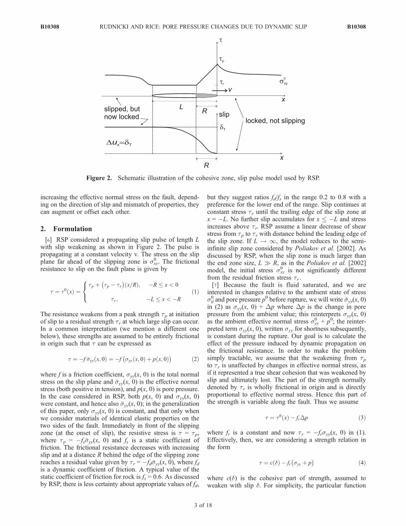
[6] RSP considered a propagating slip pulse of length Lwith slip weakening as shown in Figure 2. The pulse ispropagating at a constant velocity v. The stress on the slipplane far ahead of the slipping zone is sxy
0 . The frictionalresistance to slip on the fault plane is given by
t ¼ t0 xð Þ ¼tp þ tp � tr
� �x=Rð Þ; �R � x < 0
tr; �L � x < �R
8<: ð1Þ
The resistance weakens from a peak strength tp at initiationof slip to a residual strength tr at which large slip can occur.In a common interpretation (we mention a different onebelow), these strengths are assumed to be entirely frictionalin origin such that t can be expressed as
t ¼ �f �syy x; 0ð Þ ¼ �f syy x; 0ð Þ þ p x; 0ð Þ� �
ð2Þ
where f is a friction coefficient, syy(x, 0) is the total normalstress on the slip plane and �syy(x, 0) is the effective normalstress (both positive in tension), and p(x, 0) is pore pressure.In the case considered in RSP, both p(x, 0) and syy(x, 0)were constant, and hence also �syy(x, 0); in the generalizationof this paper, only syy(x, 0) is constant, and that only whenwe consider materials of identical elastic properties on thetwo sides of the fault. Immediately in front of the slippingzone (at the onset of slip), the resistive stress is t = tp,where tp = �fs�syy(x, 0) and fs is a static coefficient offriction. The frictional resistance decreases with increasingslip and at a distance R behind the edge of the slipping zonereaches a residual value given by tr = �fd�syy(x, 0), where fdis a dynamic coefficient of friction. A typical value of thestatic coefficient of friction for rock is fs = 0.6. As discussedby RSP, there is less certainty about appropriate values of fd,
but they suggest ratios fd/fs in the range 0.2 to 0.8 with apreference for the lower end of the range. Slip continues atconstant stress tr until the trailing edge of the slip zone atx = �L. No further slip accumulates for x � �L and stressincreases above tr. RSP assume a linear decrease of shearstress from tp to tr with distance behind the leading edge ofthe slip zone. If L ! 1, the model reduces to the semi-infinite slip zone considered by Poliakov et al. [2002]. Asdiscussed by RSP, when the slip zone is much larger thanthe end zone size, L R, as in the Poliakov et al. [2002]model, the initial stress sxy
0 is not significantly differentfrom the residual friction stress tr .[7] Because the fault is fluid saturated, and we are
interested in changes relative to the ambient state of stresssij0 and pore pressure p0 before rupture, we will write �syy(x, 0)
in (2) as syy(x, 0) + Dp where Dp is the change in porepressure from the ambient value; this reinterprets syy(x, 0)as the ambient effective normal stress syy
0 + p0; the reinter-preted term syy(x, 0), written syy for shortness subsequently,is constant during the rupture. Our goal is to calculate theeffect of the pressure induced by dynamic propagation onthe frictional resistance. In order to make the problemsimply tractable, we assume that the weakening from tpto tr is unaffected by changes in effective normal stress, asif it represented a true shear cohesion that was weakened byslip and ultimately lost. The part of the strength normallydenoted by tr is wholly frictional in origin and is directlyproportional to effective normal stress. Hence this part ofthe strength is variable along the fault. Thus we assume
t ¼ t0 xð Þ � frDp ð3Þ
where fr is a constant and now tr = �frsyy(x, 0) in (1).Effectively, then, we are considering a strength relation inthe form
t ¼ c dð Þ � fr syy þ p� �
ð4Þ
where c(d) is the cohesive part of strength, assumed toweaken with slip d. For simplicity, the particular function
Figure 2. Schematic illustration of the cohesive zone, slip pulse model used by RSP.
B10308 RUDNICKI AND RICE: PORE PRESSURE CHANGES DUE TO DYNAMIC SLIP
3 of 18
B10308

c = c(d) is chosen to make c(d) vary linearly with x, fromc(0) at the rupture tip x = 0 to 0 at x = �R. In thatinterpretation, tp � tr is simply to be regarded as a way ofwriting c(0).[8] During dynamic slip propagation, there is insufficient
time for pore fluid diffusion and conditions are undrainedexcept for the small but critical boundary layer effect alongthe fault walls that is addressed in Appendix B. This effecttakes place over a spatial scale perpendicular to the fault thatis typically on the order of a few millimeters to a few tens ofmillimeters. When the slip surface is idealized as a com-pletely impermeable plane, undrained conditions pertainright up to the surface itself and the change in pore pressureis related to total stress changes Dsij by
Dp ¼ � 1
3B Dsxx þDsyy þDszz
� �ð5Þ
where B is Skempton’s coefficient. In an infinite, isotropicand homogeneous linear elastic solid, slip on a straight,planar fault induces no change in the normal stress on thefault plane and, consequently, Dsyy vanishes on y = 0. Forplane strain, the change of the out-of-plane normal stress isgiven there by Dszz = nuDsxx where nu is the undrainedPoisson’s ratio. Thus the change in pore pressure is
Dp x; 0þð Þ ¼ � 1
3B 1þ nuð ÞDsxx x; 0þð Þ ð6Þ
where the superscript plus indicates evaluation on y = 0 as itis approached through positive values. For right-lateral slip,the pore pressure will increase on the positive side of the xaxis. Substituting (6) into (3) and subtracting the initial,ambient shear stress sxy
0 yield the change in shear stress onthe plus side of the slip plane as
Dsxy x; 0þð Þ ¼ 1
3frB 1þ nuð ÞDsxx x; 0þð Þ þ g xð Þ ð7Þ
where
g xð Þ ¼ t0 xð Þ � s0xy
¼� s0
xy � tr� �
þ tp � tr� �
1þ x=Rð Þ; �R � x < 0
� s0xy � tr
� �; �L � x < �R
8><>:
ð8Þ
[9] In Appendix B, we show that the more elaboratemodel of the near fault material leads to an expression forthe change in pore pressure that is identical to (6) but with Breplaced by B0 = BW/w, where B is now to be interpreted asthe Skempton coefficient outside the near fault borderregions (as nu is the undrained Poisson’s ratio of this region)and w and W (given in Appendix B) depend on theporoelastic properties and permeabilities of the near faultmaterials to either side (inset of Figure 1). Thus, in all thefollowing expressions, B is replaced by B0. Because W maybe either positive or negative, the pore pressure mayincrease, promoting slip by decreasing the effective com-pressive normal stress, or decrease, inhibiting slip byincreasing the effective compressive normal stress. If the
only alteration of the effective normal stress is the porepressure induced by the near slip plane dissimilarity ofproperties, then it is reasonable to assume, as did Rudnickiand Koutsibelas [1991], that the pore pressure increasecontrols propagation. However, this effect is likely to actin combination with others, such as that due to elasticdissimilarity of material farther from the fault discussed inthe next paragraph. Consequently, we will present resultsfor near slip zone arrangement of properties that bothincrease and decrease pore pressure.[10] If the materials away from the near fault region are
modeled as elastic, but with different properties on the twosides of the fault, then inhomogeneous slip at the interfaceinduces a change in normal stress Comninou [1978] andAdams [1995, 1998] in addition to the change in effectivenormal stress caused by the pore pressure (i.e., Dsyy 6¼ 0 ony = 0, as assumed above). This change may also be positiveor negative depending on the direction of slip, the directionof propagation and the mismatch of properties. In a latersection, we compare the alteration of normal stress in thiscase to the alteration of effective normal stress due to porepressure and show that the net change in effective normalstress is the combination of both effects.[11] We also note that neglecting pore pressure effects but
assuming a linear dependence of the friction coefficient, orsimply of the shear strength, on the slip rate _d leads to alinear relation of the same form as (7) between the changesin shear stress Dsxy(x, 0+) and the fault parallel stresschange Dsxx(x, 0
+) on the fault plane. This follows fromthe connection between the slip rate and the fault parallelnormal strain for steady propagation (see (B1) and thefollowing parenthetical remark). Although we do not treatthis case, the solution could be obtained from that here. Inparticular, for a friction coefficient of the form fr = fr
0 + fr1 _d,
equations in the same form as equations (7) and (8) hold,but now with tr = �fr
0syy and with frB(1 + n)/3 inequation (7) replaced by fr
1v(1 � n)syy0 /m. (An analogous
solution with velocity strengthening friction has beendeveloped recently by Brener et al. [2005] for self-healingslip pulses at a nonopening interface between deformableand rigid solids.)
3. Solution
[12] RSP have shown that the change in total stresses forsteady propagation of a Mode II rupture can be written asfollows in terms of a single analytic function M(z) of thecomplex variable z
Dsxx ¼ D�sxx �Dp
¼ 2asIm 1� a2s þ 2a2
d
� �M zdð Þ
� 1þ a2
s
� �M zsð Þ
=D
ð9aÞ
Dsyy ¼ D�syy �Dp ¼ �2as 1þ a2s
� �Im M zdð Þ �M zsð Þ½ =D
ð9bÞ
Dsxy ¼ D�sxy ¼ Re 4asadM zdð Þ½ � 1þ a2s
� �2M zsð Þ
i=D ð9cÞ
B10308 RUDNICKI AND RICE: PORE PRESSURE CHANGES DUE TO DYNAMIC SLIP
4 of 18
B10308
where zd = x + iady, zs = x + iasy, ad =
ffiffiffiffiffiffiffiffiffiffiffiffiffiffiffiffiffiffiffiffiffiffiffi1� v=cdð Þ2
q, as =ffiffiffiffiffiffiffiffiffiffiffiffiffiffiffiffiffiffiffiffiffiffiffi
1� v=csð Þ2q
, cd and cs are the dilatational and shear wave
speeds, and Re and Im stand for the real and imaginaryparts. The denominator is the Rayleigh function
D ¼ 4asad � 1þ a2s
� �2 ð10Þ
which vanishes when v equals the Rayleigh wave speed.(RSP used the notation sij
tot for what we call the total stresssij here, and used the notation sij for what we call theeffective stress �sij here.)[13] Evaluating (9a) and (9c) on the slip plane y = 0 yields
Dsxx x; 0�� �
¼4as a2
d � a2s
� �D
Im M� xð Þ
ð11aÞ
Dsxy x; 0�� �
¼ Re M� xð Þ
ð11bÞ
where the superscript plus or minus indicates the limit asy = 0 is approached through positive or negative values.Substituting into (7) then gives
Re Mþ xð Þ½ ¼ kIm Mþ xð Þ½ þ g xð Þ on � L � x � 0 ð12Þ
where, using equation (6) with B0 replacing B, as discussedfollowing equation (8)
k ¼ fr4as a2
d � a2s
� �D
� �B0 1þ nuð Þ
3
� �ð13Þ
[14] Because the shear stress is continuous on the entireplane y = 0 (including the slipping region), thesame arguments used by RSP can be used to show thatM(z) = �M (z), where �M (z) is defined by �M (z) = M �zð Þ and theoverbar denotes the complex conjugate. As a consequence,
the real and imaginary parts of M+(x) in (12) can be writtenas
2Re Mþ xð Þ½ ¼ Mþ xð Þ þM� xð Þ ð14aÞ
2iIm Mþ xð Þ½ ¼ Mþ xð Þ �M� xð Þ ð14bÞ
Substituting these into (12) and rearranging give
1þ kið ÞMþ xð Þ þ 1� kið ÞM� xð Þ ¼ 2g xð Þ on � L � x � 0 ð15Þ
The problem has been reduced to finding the function M(z)that is analytic everywhere in the cut plane and approachesvalues on either side of the cut �L � x � 0 that are relatedby (15) with (8). This is a type of problem that arisescommonly in complex variable formulations of elasticity.Detailed discussions are given by Muskhelishvili [1992] andEngland [2003]. The solution is obtained by a modifiedversion of the procedure used by RSP and is described inAppendix A. Results for a mathematically similar problemarising in supershear rupture propagation are given in theauxiliary material of Dunham and Archuleta [2005].[15] The desired function is
M zð Þ ¼ � s0xy � tr
� �� tp � tr� � cos peð Þ
pz12�e
zþ Lð Þ12þe
�Z 0
�R
1þ t=Rð Þdt
�tð Þ12�e
t þ Lð Þ12þe
t � zð Þð16Þ
where e is given by
e ¼ 1
parctan kð Þ ð17Þ
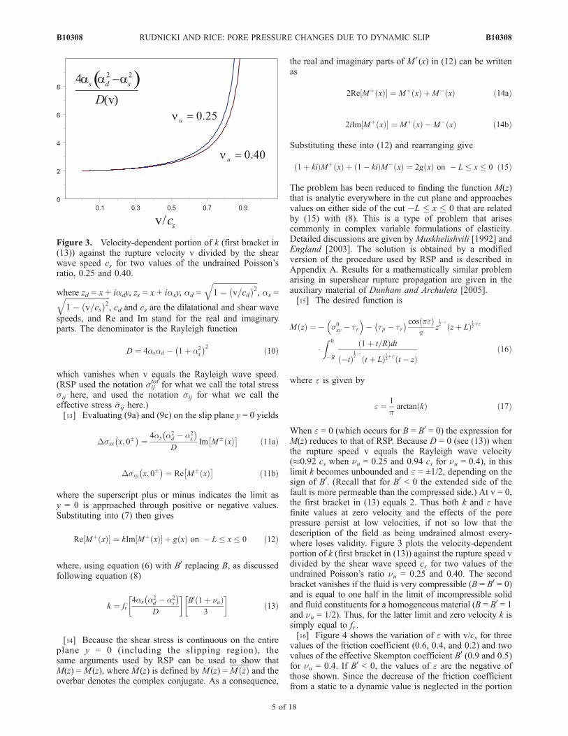
When e = 0 (which occurs for B = B0 = 0) the expression forM(z) reduces to that of RSP. Because D = 0 (see (13)) whenthe rupture speed v equals the Rayleigh wave velocity(�0.92 cs when nu = 0.25 and 0.94 cs for nu = 0.4), in thislimit k becomes unbounded and e = ±1/2, depending on thesign of B0. (Recall that for B0 < 0 the extended side of thefault is more permeable than the compressed side.) At v = 0,the first bracket in (13) equals 2. Thus both k and e havefinite values at zero velocity and the effects of the porepressure persist at low velocities, if not so low that thedescription of the field as being undrained almost every-where loses validity. Figure 3 plots the velocity-dependentportion of k (first bracket in (13)) against the rupture speed vdivided by the shear wave speed cs for two values of theundrained Poisson’s ratio nu = 0.25 and 0.40. The secondbracket vanishes if the fluid is very compressible (B = B0 = 0)and is equal to one half in the limit of incompressible solidand fluid constituents for a homogeneous material (B = B0 = 1and nu = 1/2). Thus, for the latter limit and zero velocity k issimply equal to fr .[16] Figure 4 shows the variation of e with v/cs for three
values of the friction coefficient (0.6, 0.4, and 0.2) and twovalues of the effective Skempton coefficient B0 (0.9 and 0.5)for nu = 0.4. If B0 < 0, the values of e are the negative ofthose shown. Since the decrease of the friction coefficientfrom a static to a dynamic value is neglected in the portion
Figure 3. Velocity-dependent portion of k (first bracket in(13)) against the rupture velocity v divided by the shearwave speed cs for two values of the undrained Poisson’sratio, 0.25 and 0.40.
B10308 RUDNICKI AND RICE: PORE PRESSURE CHANGES DUE TO DYNAMIC SLIP
5 of 18
B10308

multiplying the pore pressure (3) or is regarded as a separatecohesive term (4), the appropriate value of fr should liebetween the static and dynamic values and, likely, closer tothe dynamic (residual) value. The higher value of B0 mightbe more appropriate for a highly comminuted and disag-gregated fault zone that is much more permeable on thecompressive side. However, as discussed in the AppendixB, a smaller contrast in permeability and a lower shearmodulus for the near fault material on the compressive side(relative to the modulus for the less damaged materialfarther away) tends to reduce the effective value of Skemp-ton’s coefficient. This reduction is reflected by the choice ofB0 = 0.5. Figure 3 shows that the velocity-dependent portionof k (and e) does not depend strongly on nu and otherwisenu enters only as a product with B0 in the sum 1 + nu.
4. Pore Pressure
[17] Combining (6) and (11a) and using the expressionfor k (13) give the change of pore pressure on the positiveside of the y axis
frDp x; 0þð Þ ¼ �kIm Mþ xð Þf g ð18Þ
where Im{M+(x)} is the imaginary part of M(z) as yapproaches zero through positive values in �L � x � 0.This can be calculated numerically directly from (16) but isalso given by (A8) of the Appendix A. Pore pressurechanges for positive and negative values of e withmagnitudes equal to 0.1, 0.2, 0.3, 0.4, and 0.45 are plottedfor L/R = 2.0 and L/R = 5.0 in Figure 5.[18] For the six cases plotted in Figure 4, the magnitude
of e at zero velocity ranges from a few per cent (0.03 forB0 = 0.5 and fr = 0.2) to 0.15 for B0 = 0.9 and fr = 0.6. ForB0 = 0.9, e = 0.2 corresponds to v/cs equal to 0.59, 0.76 and0.87 for fr = 0.6, 0.4 and 0.2, respectively; for B0 = 0.5,e = 0.2 corresponds to v/cs equal to 0.80, 0.86 and 0.891 forfr = 0.6, 0.4 and 0.2, respectively. A magnitude of e = 0.3corresponds to rupture speeds of 0.81cs, 0.87cs, 0.91cs,0.88cs, 0.916cs and 0.93cs for the six cases plotted in
Figure 4. Magnitudes of e equal to 0.4 and 0.45 correspondto rupture speeds ranging from 0.90cs (for B
0 = 0.9, fr = 0.6)to 0.94cs (nearly the Rayleigh wave speed cr = 0.94cs fornu = 0.4) for the parameters used in Figure 4.[19] For positive values of e, the pore pressure increases
rapidly at the onset of slip at x = 0 and the largest porepressure increase is induced in the end zone near the frontof the slipping zone. The magnitude of the induced pressureincreases with e and frDp(x, 0+) can exceed 80% of
Figure 4. Variation of e with v/cs for undrained Poisson’sratio nu = 0.4, three values of the friction coefficient and twovalues of the effective Skempton coefficient B0.
Figure 5. Induced pore pressure Dp(x, 0+) multiplied bythe friction coefficient fr and divided by the cohesive zonestress drop c(0) = tp � tr. Results are shown for (a) L/R =2.0 and (b) for L/R = 5.0. Curves are labeled by positive andnegative values of e for five magnitudes: 0.1, 0.2, 0.3, 0.4,and 0.45.
B10308 RUDNICKI AND RICE: PORE PRESSURE CHANGES DUE TO DYNAMIC SLIP
6 of 18
B10308

c(0) = tp � tr for e = 0.45. Since e increases withincreasing velocity, the induced pore pressure contributesto velocity weakening. The distribution of pore pressure ismore sharply peaked in the end zone for the larger values ofe. For negative values of e, the pore pressure decreasesroughly linearly with the onset of slip at x = 0 and achievesits largest decrease near the end of the slip weakening zone(x = �R). As for positive e, the magnitude of the changeincreases with the magnitude of e and frDp(x, 0+) is about95% of tp� tr for e =�0.45. Because increasing magnitudeof e corresponds to increasing velocity, the increasingmagnitude of the pore pressure decrease (increasing effectivecompressive stress) inhibits rupture propagation.[20] The maximum induced pore pressure depends weakly
on L/R and is about the same in Figures 5a and 5b. This isshown more clearly in Figure 6, which plots the inducedpore pressure frDp (divided by c(0) = tp � tr) for e = ±0.3and L/R = 1.1, 2.0, 5.0 and the limit L/R ! 1. Themagnitude of the pore pressure change induced in the endzone increases only slightly with L/R.[21] The magnitudes of the pore pressure changes
induced outside the end zone (�L � x < �R) differsignificantly for positive and negative values of e. For e > 0,a pore pressure increase with a magnitude roughly 10 to20% of tp � tr is induced on the slipping zone outside theend zone. The magnitude is slightly larger and the decaytoward the end of the slip zone (x = �L) is slower for thesmaller values of e. Figure 6 shows that the magnitude ofthe pore pressure induced outside the end zone, although asmall fraction of t p � tr, increases with increasing L/R.The pore pressure increase induced on �L < x < �R reducesthe effective value of the residual friction stress. For amaximum magnitude of frDp outside the end zone about20% of tp � tr and the range of tr/tp = 0.2–0.8(corresponding to the range of the ratio of static to dynamicvalues of the friction coefficient fs/fd cited earlier fromRSP), frDp ranges from 0.05 to 0.80 times tr. Thus theeffective frictional resistance remains positive although itcan be reduced to as little as 20% of its nominal value.
[22] For e < 0, the magnitude of the pore pressuredecreases slowly from its largest value near the end ofthe weakening zone (x = �R) until very close to thetrailing edge of the slip zone where it drops abruptly tozero. (The different behaviors of the pore pressure at theleading and trailing edges for positive and negative e areevident from the effects on the exponents of �x and L + xin (A8)). Thus the pore pressure decrease increases theeffective value of the frictional resistance by a substantialfraction of tp � tr for the larger magnitudes of e. Fornegative e, the magnitude of the pore pressure change isgreater over a larger proportion of the slipping zone.Figure 6 shows that the effect is more dramatic for largerL/R.[23] The induced pore pressure alters the effective shear
resistance, t 0(x) � frDp(x, 0+), and changes its distributionon the slip zone. The effective shear resistance minus theresidual resistance tr (divided by tp � tr) is shown for thesame values of e in Figure 7 for L/R = 2.0 and 5.0. Forcomparison the nominal, linear distribution of shear resis-tance in the absence of pore pressure change, t0(x), minustr, is also plotted. As shown, for e > 0, the induced porepressure increase causes a much more precipitous drop inthe shear resistance with distance back from the edge of theslipping zone (x = 0). As already noted, the pore pressurecauses a reduction in the effective residual shear resistanceon the slipping region outside the end zone (negative valuesin Figure 7 for �L � x < �R). For e < 0, the pore pressuredecrease causes a more gradual decrease in the shearresistance until very near the trailing edge of the slip zoneand causes the shear resistance to remain closer to tp overthe entire slipping region (rather than dropping to tr). Forboth positive and negative e, the effect is larger for largermagnitudes and hence larger velocities. For negative e, theeffective residual shear resistance is increased much morethan it is decreased for positive e.
5. Energy Release Rate
[24] In this section, we calculate and discuss the effect ofthe induced pore pressure on the energy required to drivethe fault at given a velocity (for a given nominal slipweakening relation). For steady state propagation of theslip zone, there can be no change in the strain energy orkinetic energy. Consequently, as noted by RSP, the work ofthe applied stress on the total relative slip must equal theenergy dissipated against the frictional resistance
s0xydT ¼
Z dT
0
t0 dð Þ � frDp
dd ð19Þ
where dT = d(x = �L) is the total relative displacementaccumulated at the trailing edge of the slipping zone and t0
is regarded as a function of slip accumulated behind the tipd rather than position x (see section 6). Using Dsyy = 0,subtracting trdT from both sides, and noting that t0 � tr = 0for d(x = �R) � d � dT gives
s0xy � tr
� �dT ¼
Z d x¼�Rð Þ
0
t0 dð Þ � tr
dd � fr
Z dT
0
Dpdd ð20Þ
Figure 6. Dependence of the pore pressure changes onL/R. Results are shown for e = ±0.3 and L/R = 1.1, 2.0,5.0 and the limit L/R ! 1.
B10308 RUDNICKI AND RICE: PORE PRESSURE CHANGES DUE TO DYNAMIC SLIP
7 of 18
B10308
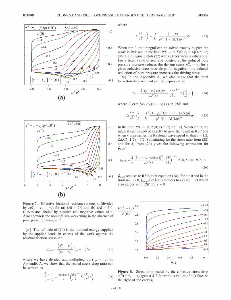
[25] The left side of (20) is the nominal energy suppliedby the applied loads in excess of the work against theresidual friction stress tr:
Gnom ¼s0xy � tr
� �tp � tr� � tp � tr
� �dT ð21Þ
where we have divided and multiplied by (tp � tr). InAppendix A, we show that the scaled stress drop ratio canbe written as
s0xy � trtp � tr
¼ cos peð Þp
R
L
� �12þe
SR
L; e
� �ð22Þ
where
SR
L; e
� �¼
Z 1
0
1� pð Þp12�e 1� R=Lð Þp½
12þe
dp ð23Þ
When e = 0, the integral can be solved exactly to give theresult in RSP and in the limit R/L ! 0, S(0; e) = 1/[(1/2 + e)(3/2 + e)]. Figure 8 plots (22) with (23) for various values of e.For a fixed value of R/L and positive e, the induced porepressure increase reduces the driving stress sxy
0 � tr for agiven cohesive zone stress drop; for negative e the inducedreduction of pore pressure increases the driving stress.[26] In the Appendix A, we also show that the total
locked-in displacement can be expressed as
dT ¼2 tp � tr� �
cos peð ÞmF vð Þ L
R
L
� �12þe
DR
L; e
� �ð24Þ
where F(v) = D(v)/as(1 � as2) as in RSP and
DR
L; e
� �¼
Z 1
0
1� pð Þ 1=2þ eð Þ � R=Lð Þp½ p12�e 1� R=Lð Þp½
12þe
dp ð25Þ
In the limit R/L ! 0, D(0; e) = 1/(1/2 + e). When e = 0, theintegral can be solved exactly to give the result in RSP andwhen v approaches the Rayleigh wave speed so that e = 1/2,D(R/L; 1/2) = 1/2. Substituting for the stress ratio from (22)and for dT from (24) gives the following expression forGnom:
Gnom ¼ 2
ptp � tr� �
cos peð Þ 2
mF vð Þ LR
L
� �1þ2e
D R=L; eð ÞS R=L; eð Þ
ð26Þ
Gnom reduces to RSP (their equation (18)) for e = 0 and in thelimit R/L ! 0, Gnom/(mdT
2/pL) reduces to F(v)/(1 + e) whichalso agrees with RSP for e = 0.
Figure 7. Effective frictional resistance minus tr (dividedby c(0) = tp � tr) for (a) L/R = 2.0 and (b) L/R = 5.0.Curves are labeled by positive and negative values of e.Also shown is the nominal slip weakening in the absence ofpore pressure changes t0.
Figure 8. Stress drop scaled by the cohesive stress dropc(0) = tp � tr against R/L for various values of e (values tothe right of the curves).
B10308 RUDNICKI AND RICE: PORE PRESSURE CHANGES DUE TO DYNAMIC SLIP
8 of 18
B10308
[27] In the absence of induced pore pressure or when theSkempton coefficient, B, is zero, Gnom is equal to theenergy dissipated against friction in excess of tr in the endzone, �R � x � 0, which is the first term on the right in(20):
GB¼0¼Z d x¼�Rð Þ
0
t0 dð Þ � tr� �
dd ð27Þ
Within the idealization here that t0 is unaffected by the porepressure, we regard GB=0 as a material parameter. For thealternative interpretation of the slip weakening as purelycohesive, expressed by (4),
GB¼0 ¼Z d x¼�Rð Þ
0
c dð Þdd ð28Þ
with c(d) = 0 for d � d(x = �R). Thus, for a given value ofGB=0, reflecting a given t versus d relation in the end zone
(in the absence of pore pressure), the effect of an increase inpore pressure is to reduce the energy that must be suppliedto drive the fault. Conversely, a decrease in pore pressureincreases the energy that must be supplied.[28] Using dd = (@d/@x)dx and changing the limits of
integration in the second term on the right in (20) yield
Gnom ¼ GB¼0 � fr
Z �L
0
Dp x; 0þð Þ @d@x
xð Þdx ð29Þ
Substituting for Dp(x, 0+) from (18), for @d/@x from (A13)and then from (A15) gives
Gnom ¼ GB¼0 �2kL
mF vð Þ1
ptp � tr� �
cos peð Þ� �2
�Z 1
0
H �xL
R;R
L
� �� �2dx ð30Þ
where we have used the change of variable x = �x/L in theintegral. Thus the second term on the right side gives theamount that the nominal energy needed to drive the fault fora fixed material fracture energy (GB=0) is reduced by aninduced pore pressure increase (e, k > 0) or increased by apore pressure decrease (e, k < 0). Dividing by GB=0 andusing (26) give the ratio
Gnom
GB¼0
¼ 1
1þ Xð31Þ
where
X ¼kR 1
0H L
R; RL
� � 2dx
p R=Lð Þ1þ2eD R=L; eð ÞS R=L; eð Þð32Þ
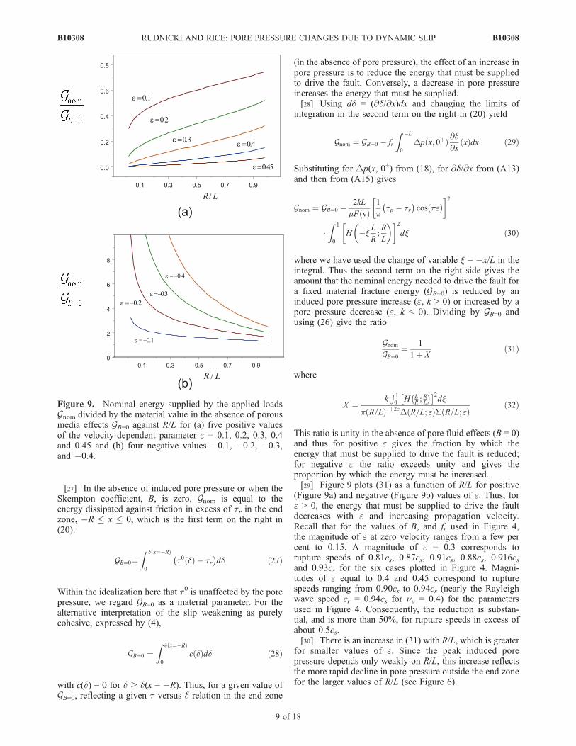
This ratio is unity in the absence of pore fluid effects (B = 0)and thus for positive e gives the fraction by which theenergy that must be supplied to drive the fault is reduced;for negative e the ratio exceeds unity and gives theproportion by which the energy must be increased.[29] Figure 9 plots (31) as a function of R/L for positive
(Figure 9a) and negative (Figure 9b) values of e. Thus, fore > 0, the energy that must be supplied to drive the faultdecreases with e and increasing propagation velocity.Recall that for the values of B, and fr used in Figure 4,the magnitude of e at zero velocity ranges from a few percent to 0.15. A magnitude of e = 0.3 corresponds torupture speeds of 0.81cs, 0.87cs, 0.91cs, 0.88cs, 0.916csand 0.93cs for the six cases plotted in Figure 4. Magni-tudes of e equal to 0.4 and 0.45 correspond to rupturespeeds ranging from 0.90cs to 0.94cs (nearly the Rayleighwave speed cr = 0.94cs for nu = 0.4) for the parametersused in Figure 4. Consequently, the reduction is substan-tial, and is more than 50%, for rupture speeds in excess ofabout 0.5cs.[30] There is an increase in (31) with R/L, which is greater
for smaller values of e. Since the peak induced porepressure depends only weakly on R/L, this increase reflectsthe more rapid decline in pore pressure outside the end zonefor the larger values of R/L (see Figure 6).
Figure 9. Nominal energy supplied by the applied loadsGnom divided by the material value in the absence of porousmedia effects GB=0 against R/L for (a) five positive valuesof the velocity-dependent parameter e = 0.1, 0.2, 0.3, 0.4and 0.45 and (b) four negative values �0.1, �0.2, �0.3,and �0.4.
B10308 RUDNICKI AND RICE: PORE PRESSURE CHANGES DUE TO DYNAMIC SLIP
9 of 18
B10308

[31] For negative values of e, the reduction in porepressure dramatically increases the energy needed to drivethe fault, by ratios exceeding 2, except when the slipweakening zone is a large fraction of the total slip zonelength (R � L). For fixed R/L, the energy requiredincreases with velocity and hence would tend to inhibitpropagation. The very large increases in energy requiredfor small R/L reflect the large decreases in pore pressureinduced outside the end zone (�L � x � �R) as shown inFigures 5 and 6.
6. Implied Slip Weakening Law
[32] The frictional shear stress t0(x) in the absence ofpore pressure has been assumed to decrease linearly withdistance behind the rupture edge as shown schematically inFigure 2. Because the resulting relative displacements onthe slip zone can be calculated, as noted by RSP (followingPalmer and Rice [1973]), the distribution of t0(x) implies arelation between t0 and the slip d. In the absence of inducedpore pressure, this relation is independent of rupture speed.Although the relation is not linear and depends on R/L, RSPshow (by comparing results for the limiting cases of R/L = 0and R/L = 1) that the departure from linearity is small andthat the dependence on R/L is weak for a fixed materialfracture energy (their G and corresponding to our GB=0).[33] In contrast to RSP, the slip weakening relation
here depends on the rupture velocity (and porous mediaparameters) through e. Figure 10 shows the effectiveshear resistance against the relative slip (multiplied byc(0)/GB=0) for L/R = 5.0 and e = ±0.2 and ±0.45. Therelation is also plotted for e = 0, corresponding to B = 0and the case considered by RSP. As shown the decrease(increase) in pore pressure for e < (>)0 causes the curveto drop more (less) rapidly for small displacements. Theareas under the curves are required to be identical (equalto one for the normalization used) by (27) and (28)
because the nominal energy release rate (for B = 0) isinterpreted as a material parameter. As in RSP, thedependence on L/R is very weak and plots for the othervalues of L/R used (1.1, 1.5, 2.0., and 10.0) are virtuallyindistinguishable from Figure 10.
7. More General Perspective on MaterialDissimilarity Effects in Dynamic Rupture
[34] In this section we compare the alteration of effectivenormal stress, due to induced pore pressure on the faultplane, with the change in normal stress induced by spatiallyinhomogeneous, mode II sliding on a plane between elasticsolids with different material properties [Comninou, 1978;Adams, 1995, 1998]. The latter effect has been studiedextensively in seismology [Weertman, 1980; Andrews andBen-Zion, 1997; Harris and Day, 1997; Cochard and Rice,2000; Ben-Zion, 2001; Xia et al., 2005]. In particular, weshow how differences in poroelastic properties in thin layersalong the fault (as in Figure 1 and in Appendix B) modifythe interpretation of material dissimilarity as it has beenconsidered thus far.[35] We adopt the formulation of Weertman [1980] for
steadily traveling slip distributions of form d = d(x � vt) onthe interface between homogeneous elastic half-spaces toillustrate the effect. In that formulation, the shear andnormal stresses are
sxy xð Þ ¼ s0xy �
�m vð Þp
Z þ1
�1
dd x0ð Þ=dx0x� x0
dx0 ð33Þ
syy xð Þ ¼ s0yy � m* vð Þdd xð Þ=dx ð34Þ
The functions, labeled �m(v) and m*(v) by Weertman, aredefined in terms of his additional functions of rupturespeed v
ai ¼ffiffiffiffiffiffiffiffiffiffiffiffiffiffiffiffiffiffiffiffiffiffi1� v2=2c2si
q; bi ¼
ffiffiffiffiffiffiffiffiffiffiffiffiffiffiffiffiffiffiffiffi1� v2=c2si
q; gi ¼
ffiffiffiffiffiffiffiffiffiffiffiffiffiffiffiffiffiffiffiffi1� v2=c2di
qð35Þ
with i = 1 or 2. Weertman’s subscript 1 refers to thematerial in y > 0 (where we previously denoted the near-fault material by plus), and 2 refers to that in y < 0 (withnear-fault material denoted minus above). The a hereshould not be confused with earlier uses of that symbol; band g correspond to as and ad, respectively, as introducedearlier. In terms of those functions [Weertman, 1980], withmisprint corrections by Cochard and Rice [2000], �m(v) andm*(v) are
�m ¼ 2m1m2
D1 þD2
m1g2 1� a22
� �g1b1 � a4
1
� �þm2g1 1� a2
1
� �g2b2 � a4
2
� �ð36Þ
m* ¼ 2m1m2
D1 þD2
m1 g1b1 � a41
� �g2b2 � a2
2
� ��m2 g2b2 � a4
2
� �g1b1 � a2
1
� �ð37Þ
Figure 10. Relation for the cohesive part of the stress dropc(d), divided by c(0) = tp � tr, versus relative slip,multiplied by c(0)/GB=0, implied by the solution. Shown forL/R = 5.0 and several values of e.
B10308 RUDNICKI AND RICE: PORE PRESSURE CHANGES DUE TO DYNAMIC SLIP
10 of 18
B10308

where
D1 ¼ m1m2 1� a21
� �1� a2
2
� �g2b1
þ g1b1 � a2
1
� �g2b2 � a2
2
� �þ m2
2 1� g1b1ð Þ g2b2 � a42
� �ð38Þ
D2 ¼ m1m2 1� a21
� �1� a2
2
� �g1b2
þ g1b1 � a2
1
� �g2b2 � a2
2
� �þ m2
1 1� g2b2ð Þ g1b1 � a41
� �ð39Þ
In the references cited, D1 + D2 above is written simply asD, but both D1 and D2 are needed for the present purposes.[36] When the two materials are identical, as in the
treatment of the materials far from the fault in the earlierpart of this paper, m? = 0 and
�m vð Þ ¼ m gb � a4ð Þb 1� a2ð Þ ð40Þ
(dropping the subscript i). When v! 0, this �m = m(1� cs2/cd
2) =m/[2(1 � n)] where, in the present undrained context, ncorresponds to nu. The combination gibi � ai
4 is theRayleigh function for material i; that is, it vanishes (otherthan at v = 0) at v = cRi. Thus (40) shows that when the twohalf-spaces are identical, �m(v) = 0 at their common Rayleighspeed cR.[37] When the half-spaces are dissimilar, a generalized
Rayleigh speed cGR is defined as the value of v > 0, if suchexists, for which �m vanishes, i.e., �m(cGR) = 0. Such a cGRexists for modest dissimilarity of properties, typically forshear wave speeds different by less than 20–30%, acondition that often seems to be met for natural faults[Andrews and Ben-Zion, 1997]. When v = cGR, (33) showsthat nonuniform slip does not alter the shear stress but(34) shows that it does alter the normal stress, in a tensiledirection when m* > 0. (Note that _d = �vdd/dx, so that if_d � 0 and v > 0, as implicitly assumed here, dd/dx � 0.)Exchanging the two half-spaces for one another or, equiv-alently, running the same slip history in the oppositedirection along the interface, changes the sign of m*. Ingeneral, m* > 0 if the wave speeds of material 1 are less thanthose of material 2, and vice versa; expressed differently[Andrews and Ben-Zion, 1997], normal stress clamping isdecreased by nonuniform slip when the direction of prop-agation of the slip pattern is the same as the direction of thefault wall shear displacement in the slower material.[38] Weertman [1980] suggested the possibility of, and
Adams [1998] and Rice [1997] made explicit, simplesolutions of (33) and (34), together with a Coulomb frictionlaw syx = �fsyy with constant f, for which pulses of slippropagate at cGR. They involve constant _d in all slidingregions, when 0 < syx
0 < �fsyy0 [see Cochard and Rice,
2000].[39] The dissimilarity of elastic material away from the
fault on the two sides, in addition to differences very nearthe fault predicted in the inset of Figure 1, alters thecalculation of pore pressure described in Appendix B. Inparticular, the condition that the fault parallel strains are ofequal magnitude, �xx
+ = ��xx� , is no longer satisfied. Instead, a
further analysis of the Weertman [1980] derivations leading
to (33) and (34) shows that the extensional strains along thefault walls are
�þxx ¼ �xx;1 ¼1þ c2
dddx
; ��xx ¼ �xx;2 ¼ � 1� c2
dddx
ð41Þ
where
c ¼ D1 �D2ð Þ= D1 þD2ð Þ ð42Þ
c reverses sign when we exchange one half-space for theother or, for a given position of the two materials, reversethe rupture propagation direction. In terms of thoseexpressions, the result in the Appendix B for the porepressure change on the fault plane, (B9) with (B10), is nowaltered to
pf ¼ �W vð Þ2
dddx
ð43Þ
where
W vð Þ ¼ Zþwþ � Z�w�
Zþ þ Z� þ c vð Þ Zþwþ þ Z�w�
Zþ þ Z�
� m* vð Þ Zþwþ=mþ þ Z�w�=m�
Zþ þ Z� ð44Þ
The first term inW(v) is the same as before and independentof velocity. The second term, proportional to c(v), resultsbecause the along fault extensional strains are no longer ofidentical magnitude on the two sides. The third term,proportional to �m?(v), occurs because a nonzero change insyy is induced in the bimaterial case. The coefficients ofc(v) and �m?(v) are averages of w and w/m, on the twosides of the fault, weighted by Z±, respectively. Thus theequations for pore pressure and effective stress, correspond-ing to (33) and (34), are now
p xð Þ ¼ p0 �W vð Þ2
dd xð Þdx
; ð45Þ
syy xð Þ þ p xð Þ ¼ s0yy þ p0
� �� m? vð Þ þW vð Þ
2
� �dd xð Þdx
; ð46Þ
The latter shows that the proper measure of the propensityfor slip to alter effective normal stress is the sum of theWeertman m? and the poroelastic W/2 derived here. Eitherterm may be positive or negative depending on thedissimilarity of properties adjacent to or farther from theslip zone, the direction of propagation and the sense ofslip.[40] As an example, consider material 1 (or plus) to be
slightly more compliant and to have a slightly lower shearwave velocity than material 2 (or minus). In particular, cs1 =0.90cs2 and cd1/cs1 = cd2/cs2 =
ffiffiffi3
p, corresponding to m1 =
0.75m2, r1 = 0.923r2 and n1 = n2 = 0.25. For this choice ofPoisson’s ratio (here to be interpreted as the undrainedvalue), the Rayleigh wave speed in each material is 0.92times the respective shear wave velocity. The generalizedRayleigh wave velocity, at which �m(cGR) = 0, is cGR =
B10308 RUDNICKI AND RICE: PORE PRESSURE CHANGES DUE TO DYNAMIC SLIP
11 of 18
B10308

0.87cs2 for these choices. Figure 11 plots c (42), andFigure 12 plots m?(v)/m2 as functions of velocity (dividedby cs2) up to cGR. In this case both c and m? are positive, butexchanging the two materials or reversing the direction ofslip introduces a negative sign. The magnitudes of both cand m increase as v approaches cGR, but both are finite there(c = 0.155, m?/m2 = 0.178).[41] Figure 12 also plots values for W/2m2 in order to
compare the magnitudes of the bimaterial and porous mediaeffects on alteration of the normal stress. As discussed inAppendix B, the properties entering W pertain to the near-fault material. Consequently, we choose the shear moduli,m+and m�, entering W, (B10) with (B3), to be the same andequal to the average of the two shear moduli away from thefault, called m here, and the Poisson’s ratios again to be0.25. Although B is often taken to be 0.9 for fault gouge[Roeloffs and Rudnicki, 1985; Rudnicki, 2001], we note inAppendix B that differences in properties on the two sidesof the fault and the likelihood of greater damage near thefault tends to reduce the magnitude of the effective value ofB although it may be of either sign. In addition, Roeloffs[1988] has discussed evidence for decreases in B withincreasing effective stress, suggesting that smaller valuesare more appropriate for earthquake depths. Consequently,we have taken B = 0.6 for the material on both sides of thefault in plotting Figure 12. For this example, because thenear properties are assumed to differ only in the values ofthe product kb, (44) simplifies to
W vð Þ ¼ wZþ � Z�
Zþ þ Z� þ c vð Þ � m* vð Þ=m� �
ð47Þ
where w+ = w� = w and m+ = m� = m. Results are shown inFigure 12 for values of the ratio k+b+/k�b� equal to 1, 10,5, 2 and 1, 0.5, 0.2, 0.1 and 0. Since m?(cGR)/m = 0.204exceeds c(cGR) = 0.155, the sum of the latter two termschanges from positive to negative and causes the slightdownturn in values of W(v)/2 as v approaches cGR. Values
of k+b+/k�b > 1, so that the first (constant) term in W is >0,correspond to a more permeable compressive side of thefault; values less than one, making that firstW term less thanzero, correspond to a more permeable extensile side. (Ingeneral, that is, for different values of the shear modulusand Skempton’s coefficients on the two sides of the fault,the sign of the first term in (44) for W depends on the fullmismatch of properties, not just on the ratio k+b+/k�b�).Even if the materials bounding either side of the fault haveidentical properties, there is still a pore pressure induced ifthere is elastic mismatch farther from the fault (i.e., thecontribution to the pore pressure then comes entirely fromthe latter two terms in (44)).[42] Figure 12 shows that the alteration of the effective
normal stress due to the induced pore pressure change maybe of either sign and is comparable in magnitude to thealteration due to the elastic mismatch. The rapid increase ofm?/m2 as v approaches cGR suggests, however, that the effectof the elastic mismatch will dominate near this limit, at leastif B is not too large (larger values of B increase W) andmismatch in permeability is not extreme. If the half-spacesare exchanged so that the material in y > 0 is less compliant(has a greater shear wave speed), then the same plot (Figure 12)applies with the sign of the vertical axis reversed and thevalues of k+b+/k�b� replaced by their reciprocals. Thus, ingeneral, any of the terms due entering (44) may be positiveor negative and the sign of the term due to near faultheterogeneity (first in (44)) may differ from that of termsdue to elastic dissimilarity (sum of last two entering (44)).Therefore the sign and magnitude of the alteration of theeffective normal stress depends not only on the elasticdissimilarity of the materials bounding the fault but also ontheir differences from the material very near the slip surfaceand the differences of the poroelastic properties of this
Figure 11. Plot of c, equation (42), against v/cs2 up to v = cGRfor m1 = 0.75m2, r1 = 0.923r2 and n1 = n2 = 0.25 so thatcs1 = 0.90cs2, cd1/cs1 = cd2/cs2 =
ffiffiffi3
pand cGR = 0.87cs2.
Figure 12. Plot of m*(v)/m2 against v/cs2 for the same elasticmismatch as in Figure 11: m1 = 0.75m2, r1 = 0.923r2 andn1 = n2 = 0.25 so that cs1 = 0.90cs2, cd1/cs1 = cd2/cs2 =
ffiffiffi3
p
and cGR = 0.87cs2. Remaining curves showW/2m2 for differentvalues of the ratio of the product of the near fault permeabilityand compressibility on the two sides of the fault, k+b+/k�b�.On both sides of the fault, the near fault shear modulus is takento be the average of values farther from the fault, B = 0.6 andn = 0.25.
B10308 RUDNICKI AND RICE: PORE PRESSURE CHANGES DUE TO DYNAMIC SLIP
12 of 18
B10308

material on the two sides of the zone of concentratedsliding.
8. Discussion
[43] We have calculated the pore pressure induced by slippropagation for a model that idealizes recent detailed studiesof fault zone structure [Chester et al., 1993; Chester andChester, 1998; Lockner et al., 2000;Wibberley and Shimamoto,2003; Sulem et al., 2004; Noda and Shimamoto, 2005]. Inparticular, slip is modeled as occurring on a plane boundedby material with permeabilities and poroelastic propertiesthat are different on each side of the slip plane and from theproperties of the elastic material farther from the fault. Thepore pressure change is the result of poroelastic deformationof the fault wall; changes due to inelastic porosity changes,dilation or compression, of the fault zone material would bein addition to these. Although the detailed calculations arecarried out for the limiting case in which the compressiveside of the slip zone is much more permeable than theextensile side, we have shown that they can be applied tothe more elaborate model simply by modifying the effectivevalue of the Skempton coefficient. In particular, by chang-ing the sign of the effective Skempton’s coefficient frompositive to negative treats the case in which the extensileside of the fault is more permeable.[44] Induced pore pressure by poroelastic compression
discussed here is one of a number of mechanisms that havebeen suggested for dynamic weakening of slip resistanceduring earthquakes. These include thermal pressurization ofpore fluid [Lachenbruch, 1980; Mase and Smith, 1987;Garagash and Rudnicki, 2003a, 2003b; Garagash et al.,2005; Rice, 2006], flash heating of asperity contacts [Rice,1999; Tullis and Goldsby, 2003; Rice, 2006] and others[Sibson, 1975; Spray, 1993, 1995; Goldsby and Tullis,2002; Chambon et al., 2002]. For the most part, theserequire rapid slip to generate heat sufficiently rapidly andrelatively large slip to generate sufficiently high temperature(although Segall and Rice [2006] have shown that shearheating can be significant toward the end of the nucleationperiod, before slip velocities become seismic). Although themechanism discussed here increases in magnitude withincreasing velocity of propagation, it is also operative atsmall slip and at low velocities. Consequently, it may be afactor in allowing sufficient slip to occur long enough forother mechanisms to come into play or for preventingincipient slip from progressing, depending on the sign ofthe induced pore pressure change.[45] The model provides a more general framework for
considering the effects of material heterogeneities perpen-dicular to the fault on alterations of the effective normalstress. Previous studies [Weertman, 1980; Andrews andBen-Zion, 1997; Harris and Day, 1997; Cochard and Rice,2000; Ben-Zion, 2001; Xia et al., 2005] have focused on thealteration of normal stress induced by inhomogeneous slipat the interface between elastic solids with different prop-erties. The calculations here show that alterations of com-parable magnitude in the effective normal stress can resultfrom pore pressure changes induced by heterogeneousproperties. More specifically, pore pressure changes resultfrom differences in the permeability and poroelastic prop-erties of the material on the two sides of the slip zone and
from differences in the properties of this near fault materialfrom that farther from the fault. Although parameter valuesare uncertain, a comparison of the magnitude of the twoeffects suggests that the effect due to nonuniform slipbetween different elastic solids may dominate as the rupturevelocity approaches the generalized Rayleigh speed for thebimaterial, at least if the effective Skempton’s coefficient isnot too large, and the ratio of permeabilities is neither verylarge nor very small.[46] Even when the effect due to elastic dissimilarity of
material away from the fault is dominant, pore pressurechanges due to near fault heterogeneity may augment orcounteract the bimaterial effect. The sign of both effects canbe positive or negative depending on the heterogeneity andthe direction of slip and propagation. For example, thenormal compressive stress is reduced by nonuniform slipwhen the direction of propagation of the slip distribution isthe same as the direction of the fault wall displacement inthe slower material. This reduction might, however, bediminished by a increase in effective compressive stress,due to a decrease in pore pressure, if the extensile side ofthe fault is more permeable. Thus the net effect of slip onthe effective normal stress will depend on the details of theproperties, both elastic and poroelastic, of the materialbounding the zone of concentrated slip.[47] Here the slip zone is assumed to occur at the
interface of the two materials. Fault zone studies [Chesteret al., 1993; Chester and Chester, 1998; Lockner et al.,2000; Wibberley and Shimamoto, 2003; Sulem et al., 2004;Noda and Shimamoto, 2005] do show that the principal slipsurface is very narrow, less than about 1 to 5 mm, and thusreasonably idealized as a planar discontinuity for somepurposes. Such studies also show that the relatively imper-meable fault core is a wider zone of 10 mm to hundreds ofmillimeters and bounded by a more permeable, damagedzone (grading to undamaged material farther from the fault).The model shown in the inset of Figure 1 is consistent withslip occurring at the boundary of these two zones. If onlythe effect of near fault heterogeneity is considered, and theslip zone is plausibly assumed to take a path of leastresistance where the effective compressive normal stress isleast, then the results here indicate that the slip zone willchoose a path where the compressive side is more perme-able. For the direction of slip (right lateral) and propagation(to the right) shown in Figure 1, this is consistent with thepositive material being the less permeable ultracataclasticcore and the negative material being the adjacent morepermeable, damage layer. Of course, this simple picturecould be complicated by a variety of other effects. Never-theless, in a recent numerical study of the bimaterial effect,Brietzke and Ben-Zion [2006] found that when several slipsurfaces were possible, the rupture tended to choose amaterial interface where the compressive normal stresswas reduced. It is possible to speculate that when the porepressure changes due to material heterogeneity are included,the rupture tends to choose the interface where the reductionof effective normal stress is greatest, though this is certainlyan issue in need of further study.[48] Another issue in need of further study is the effect of
near fault damage induced by slip propagation. In contrastto the scenario of the previous paragraph, such damage mayhave an effect which, typically, acts oppositely to the
B10308 RUDNICKI AND RICE: PORE PRESSURE CHANGES DUE TO DYNAMIC SLIP
13 of 18
B10308

reduction of compressive normal stress due to far fieldelastic dissimilarity, by inducing negative pore pressurechanges (suctions) along the slip surface. If there is no oronly very small far field material dissimilarity, then thesuctions will dominate and cause an increase in the effectivenormal compression, and hence partial stabilization of thefault. This possibility arises because a variety of studies[Poliakov et al., 2002; Kame et al., 2003; Rice et al., 2005;Andrews, 2005; Ben-Zion and Shi, 2005] have shown thatunless the direction of maximum principal stress is at anunusually shallow angle with the fault, say, less than �25degrees, then stresses predicted near the rupture front areexpected to cause Mohr-Coulomb failure and damagepreferentially on the extensile side of the slipping plane.Such preference is supported by field evidence [Poliakov etal., 2002]. Ben-Zion and Shi [2005] have shown this sametendency for damage on the extensile side in simulations ofrupture along an interface between elastically dissimilarmaterials. The spatial extent of the damaged zone ispredicted to decrease with depth [Rice et al., 2005] butthe preferred side for damage remains. Presumably, thisdamage would increase the permeability on the extensileside whereas, conversely, compression of the other side mayreduce the permeability there. The results here indicate thatthis effect, unless compensated by decrease of total com-pressive stress due to far field material dissimilarity, woulddecrease the pore pressure and hence increase the effectivecompressive stress and the energy required to propagate thefault. Ben-Zion and Shi [2005] have shown that includingthe effects of damage induced by rupture can modify andpartially stabilize some aspects of the bimaterial effect.Further study of the effect on damage on altering the nearfault permeability structure is needed.
9. Conclusion
[49] Interaction of pore fluid with material heterogeneitynear the slip zone that is representative of that observed infault zones can affect rupture propagation. An increase ofpore pressure that reduces the effective compressive stressand facilitates slip propagation occurs if the compressiveside of the slip zone (modeled as a plane) is more permeablethan the tensile side; conversely, a decrease of pore pressurethat increases the effective compressive stress and inhibitsslip propagation occurs if tensile side is more permeable.Although a more complex and realistic model will undoubt-edly alter the details of the calculations here, the mainconclusion that near fault heterogeneity affects rupturepropagation is unlikely to change. Understanding of howthe particular effect studied here, pore pressure changes dueto heterogeneous poroelastic properties, interacts with avariety of other effects must await further modeling andobservational studies.
Appendix A: Details of the Solution
[50] The function M(z) is analytic everywhere in the cutplane and approaches values on either side of the cut �L �x � 0 that are related by (15). The solution proceeds by firstfinding a function that satisfies the homogeneous equation((15) with zero right hand side). Although there is a formalprocedure for this [Muskhelishvili, 1992; England, 2003], it
is straightforward to verify that the complex function z/(z +L)(1/2)�e, with branch cut taken on y = 0, �L � x � 0,satisfies (15) with zero right side.[51] Because any analytic function multiplied by this
function is also a solution to the homogeneous equationand because it will be convenient to have a solution thatdecays as z�1 as jzj ! 1, we take the homogeneoussolution to be
c zð Þ ¼ 1
zþ Lð Þ12�e
zð Þ12þe
ðA1Þ
Dividing both sides of (15) by c+(x) and using thehomogeneous equation yields
M xð Þc xð Þ
� �þ� M xð Þ
c xð Þ
� ��¼ 2g xð Þ
1þ kið Þcþ xð Þ ðA2Þ
Equation (A2) has the solution [Muskhelishvili, 1992;England, 2003]
M zð Þc zð Þ ¼ 1
pi 1þ kið Þ
Z 0
�L
g tð Þcþ tð Þ
dt
t � zþ A
pðA3Þ
where A is a constant.[52] The constant A is determined by the condition that
the singularity inM(z) vanish as z! 0. This results from thephysical requirement that the slip weakening zone causesthe relative displacement to vanish smoothly at the edge ofthe slipping zone. Setting z(1/2)+eM(z) equal to zero in thelimit z ! 0 yields
A ¼ cos peð ÞZ 0
�L
g tð Þ Lþ tð Þ12�e
�tð Þ12�e
dt ðA4Þ
where cos(pe) = 1/ffiffiffiffiffiffiffiffiffiffiffiffiffi1þ k2
p. The slip must, however, also cease
smoothly at the trailing edge of the slipping zone, x = �L.This leads to the additional requirement on A that resultsfrom setting (z + L)(1/2)�eM(z) equal to zero in the limitz ! �L:
A ¼ � cos peð ÞZ 0
�L
g tð Þ �tð Þ12þe
t þ Lð Þ12þe
dt ðA5Þ
Equating the two expressions (A4) and (A5) for A yields thefollowing constraint on g(t)
Z 0
�L
g tð Þ�tð Þ
12�e
t þ Lð Þ12þe
dt ¼ 0 ðA6Þ
Substituting from (A4) for A and c(z) into (A3) and thenusing the constraint equation (A6) yield
M zð Þ ¼ � cos peð Þp
z12�e
zþ Lð Þ12þeZ 0
�L
g tð Þdt
�tð Þ12�e
t þ Lð Þ12þe
t � zð ÞðA7Þ
B10308 RUDNICKI AND RICE: PORE PRESSURE CHANGES DUE TO DYNAMIC SLIP
14 of 18
B10308

When g(t) is substituted from (8), the integral in the termmultiplying (sxy
0 � tr) can be done using contourintegration by means similar to those described by RSP.The resulting expression for M(z) is (16) in the text. TheIm{M+(x)}, which is needed to obtain the pore pressure canbe calculated numerically directly from (16) and is alsogiven by
Im Mþ xð Þf g ¼ tp � tr� � cos peð Þð Þ2
pR�xð Þ
12�e
Lþ xð Þ12þe
�Z 1
0
1� sð Þdss12�e
L=Rð Þ � s½ 12þe
sþ x=Rð Þ½ ðA8Þ
where the change of variable t = �sR has been used in theintegral.
A1. Stress Drop
[53] Substitution of the expression for g into (A6) gives arelation between the ratio of the driving stress (sxy
0 � tr) tothe cohesive zone stress drop (tp � tr) and the scaledcohesive zone size R/L:
s0xy � trtp � tr
¼
R 0
�R1þ t=Rð Þ= �tð Þ
12�e
t þ Lð Þ12þe
h idtR 0
�L1= �tð Þ
12�e
t þ Lð Þ12þe
h idt
ðA9Þ
The integral in the denominator can be evaluated byconverting it to a contour integral around the branch cut�L � x < 0 in the complex plane and the result is
Z 0
�L
1= �tð Þ12�e
t þ Lð Þ12þe
h idt ¼ p= cos peð Þ ðA10Þ
Using (A10) and the substitution p = �t/R in the integral inthe numerator of (A9) gives (22) of the text.
A2. Relative Slip Displacements
[54] The variation of the relative displacement can bewritten as
@d@x
xð Þ ¼ 2�xx x; 0þð Þ ¼ 1� nuð Þm
Dsxx x; 0þð Þ ðA11Þ
Substituting for Dsxx(x, 0+) from (9a) and using the identity
(with Poisson’s ratio taken as the undrained value)
1� nu ¼1� a2
s
� �2 a2
d � a2s
� � ðA12Þ
give
@d@x
xð Þ ¼ 2
mF vð Þ Im Mþ xð Þf g ðA13Þ
where F(v) is defined following (24). Integrating and notingthat d = 0 at x = 0 give
d xð Þ ¼2 tp � tr� �pmF vð Þ cos peð Þ
Z x
0
Hs
R;R
L
� �ds ðA14Þ
where
Im Mþ xð Þf g ¼ 1
ptp � tr� �
cos peð ÞH x
R;R
L
� �ðA15Þ
[55] Evaluating d(x) from (A14) at x = �L gives the total,locked-in displacement that has accumulated at the trailingedge of the slip zone dT. This total displacement can,however, be obtained directly by the same arguments usedby RSP and Poliakov et al. [2002]. They show that dT isproportional to A and is given by
dT ¼2Aas 1� a2
s
� �mD
ðA16Þ
Using (A4) for A and substituting the expression for g(t)from (8) yield
A ¼ tp � tr� �
cos peð ÞZ 0
�R
1þ t=Rð Þ Lþ tð Þ12�e
�tð Þ12�e
dt
� s0xy � tr
� �cos peð Þ
Z 0
�L
Lþ tð Þ12�e
�tð Þ12�e
dt ðA17Þ
If the second integral is denoted I, then dI/dL is equal to(1/2� e) times the integral in (A10). Using this result and (22)and combining the integrals make it possible to write A as
A ¼ LR
L
� �12þe
DR
L; e
� �ðA18Þ
where D(R/L; e) is given by (25). Substituting (A18) into(A16) gives (24) of the text. This expression for dT agreeswith (A14) evaluated at x = �L.
Appendix B: Pore Pressure at the Fault Plane
[56] In the main text the fault has sometimes beendescribed, for simplicity, as a completely impermeableplane of displacement discontinuity in a uniform material,with pore pressure on the compressed side entering thefriction law. Although it is a reasonable approximation toassume uniform material properties at some distance awayfrom the fault, detailed examinations of fault zones [Chesteret al., 1993; Chester and Chester, 1998; Wibberley andShimamoto, 2003] show that the fault walls are often bor-dered by materials that are different from each other andfrom the uniform material farther away. In this Appendix, weshow the effect of these different near fault properties,including the actual finite, if small, permeabilities of thematerials involved (leading to a continuous pore pressurevariation across the fault plane), can be included by modifyinga parameter of the analysis based on discontinuous pressureat an impermeable plane in a uniform material. In particular,we assume that these regions of different properties border-ing the fault are thin enough that they can be considered toundergo a uniform x direction strain exx
+ (t) on one side of thefault and an equal and opposite strain exx
�(t) = �exx+ (t) on the
other side (Figure 1, inset). Because those bordering zonesare presumed to be thin (compared, say, to the along-strike
B10308 RUDNICKI AND RICE: PORE PRESSURE CHANGES DUE TO DYNAMIC SLIP
15 of 18
B10308

length scales R and L), the strains will be essentially identicalto those calculated along the fault walls for the uniformmaterial model in the body of the paper. These fault-parallelstrains are related to the slip rate _d at a fixed position x andrupture velocity v by
eþxx tð Þ ¼ �e�xx tð Þ ¼ � _d=2v ðB1Þ
where the compressive side of the fault is assumed to bey > 0. (Because the solution is steady state 2exx
+ = @d/@x =�(1/v)@d/@t and this expression is consistent with (A11).)The strains are calculated as in the main text, based on thesolution for an impermeable fault plane in uniform material.[57] The hydraulic diffusivity ahy of fault gouge at
representative seismogenic depths is generally estimatedas being in the range of 1–10 mm2/s [Rice, 2006], andthe duration t of slip at a point in large earthquakes istypically of the order of 1 s for every 1 m of slip [Heaton,1990]. Thus the thickness of the region over which fluiddiffusion smooths out the discontinuity of the impermeablefault model, of the order of a few times
ffiffiffiffiffiffiffiffiahyt
p, will not
generally be larger than a few tens of millimeters. Thus weare concerned here with the properties and poromechanicalresponse of border regions of that order of thickness alongthe fault walls.[58] Now consider a magnified view of such border
regions along the fault plane, so that they appear as twohalf planes subjected to a uniform x direction strain exx
+ (t) iny > 0 and an equal and opposite strain exx
�(t) = � exx+ (t) in y < 0.
The two half-spaces are assumed to be deforming underplane strain conditions (ezz = 0) and are subjected to thesame fault normal stress syy, which remains constant duringslip. The shear stress sxy does vary but that does not affectthe pore pressure under these conditions, assuming that theborder regions are isotropic, or are aleotropic with principaldirections aligned with the x and y directions. What is thepore pressure pf (t) induced at the fault plane y = 0?[59] To answer this question, first imagine that the plane
y = 0 is completely impermeable. Then the pore pressurechanges p0
±(t) from the ambient value are uniform in eachhalf-space and given by
p�0 tð Þ ¼ �w�e�xx tð Þ ðB2Þ
The w± for each poroelastic half-space for undrained, planestrain conditions and constant syy is [Rice and Cleary, 1976]
w� ¼ 2m� B� 1þ n�u� �
3 1� n�u� � ðB3Þ
when the border regions are isotropic, where ± refer to thelocal, near fault properties in y b 0. The factor B±(1 + nu
±)/3(1 � nu
±) attains its maximum value, unity, for B± = 1 andnu± = 1/2 which is the case when both solid and fluid
constituents are incompressible. Note that the near faultstrains exx
± (t) (assumed spatially uniform in this magnifiedview) are related to sxx
± from the analysis of the text by theuniform properties m and nu away from the fault, i.e.,
e�xx tð Þ ¼ 1� nuð Þs�xx=2m ðB4Þ
[60] If the plane y = 0 is not completely impermeable,then spatially dependent pore pressure changes p(y, t) willdevelop in each half-space. The difference between thesefields and the uniform, undrained pore pressure (B2) sat-isfies a homogeneous diffusion equation in each half-space[e.g., Rice and Cleary, 1976]:
@
@tp y; tð Þ � p�0 tð Þ
¼ a�
hy
@2
@y2p y; tð Þ � p�0 tð Þ
ðB5Þ
where ± again refer to y > 0 and y < 0, and ahy± are the
hydraulic diffusivities. The hydraulic diffusivities can bewritten as k±/hfb
±, where k± are the permeabilities, b± arethe storage coefficients and hf is the fluid viscosity, which isthe same in both half-spaces. The diffusion equations mustbe solved in the two domains y > 0 and y < 0, subject to twoconditions at the interface y = 0. The first is that the porefluid pressures be the same (i.e., p is continuous),
p y ¼ 0þ; tð Þ ¼ p y ¼ 0�; tð Þ ¼ pf tð Þ ðB6Þ
where pf (t) is the pore pressure on the fault that we seek.The second is the fluid flux across the interface (given byDarcy’s law) is continuous
kþ@p
@yy ¼ 0þ; tð Þ ¼ k�
@p
@yy ¼ 0�; tð Þ ðB7Þ
[61] Solution by Laplace transform shows that the porepressure on the fault is given by
pf tð Þ ¼ Zþpþ0 tð Þ þ Z�p�0 tð ÞZþ þ Z� ðB8Þ
where Z± =ffiffiffiffiffiffiffiffiffiffiffik�b�
p. Substituting from (B2) and using
exx�(t) = �exx
+ (t) gives
pf tð Þ ¼ �Weþxx tð Þ ¼ �W
2
dddx
ðB9Þ
where
W ¼ Zþwþ � Z�w�
Zþ þ Z� ðB10Þ
In the body of the paper we generalize the last pair ofequations to the case of two elastically dissimilar half-spaces adjoining the fault, each lined with a narrow fault-bordering layer whose poroelastic properties define the w±
and Z± as here. Substituting (B4) yields
pf tð Þ ¼ � 1
3BW=wð Þ 1þ nuð ÞDsþ
xx tð Þ ðB11Þ
where w here is defined as in (B3), B is the Skemptoncoefficient, and both are based on the properties fartherfrom the fault. Thus the fault pore pressure is defined by thesame relation as in a homogeneous material
pf tð Þ ¼ � 1
3B0 1þ nuð ÞDsþ
xx tð Þ ðB12Þ
B10308 RUDNICKI AND RICE: PORE PRESSURE CHANGES DUE TO DYNAMIC SLIP
16 of 18
B10308

where B0 = BW/w. Note, however, from (B10) that W neednot be positive, and thus B0 may be of either sign, dependingon material properties in the two border regions. With thisinterpretation of B as B0, the solution for a uniform materialwith an impermeable fault plane, given in the main text,applies as well for the more realistic model of thisAppendix. The case B0 > 0 corresponds to weakening thefault by induced pore pressure, and B0 < 0 to strengtheningby induced pore suction.[62] As a simple case, assume that all the near fault
properties, except for the permeabilities, are identical tothose of the homogeneous material farther from the fault.Then B0 reduces to
B0 ¼ B1�
ffiffiffiffiffiffiffiffiffiffiffiffiffik�=kþ
p1þ
ffiffiffiffiffiffiffiffiffiffiffiffiffik�=kþ
p( )
ðB13Þ
Hence, when the permeability of the extensional side ismuch less than that of the compressional, k� � k+, then B0 = B.If k�/k+ = 10�2, which might be representative of havingultracataclasite on the extensional side and a coarser gougeor densely cracked material from the damaged fault core onthe compressional side, based on properties inferred fromLockner et al. [2000] andWibberley and Shimamoto [2003],then B0 ’ 0.82B; if k�/k+ = 10�1, B0 ’ 0.52B. So the effectof decreasing permeability of the part of the fault core onthe extensional side is to reduce the effective value ofSkempton’s coefficient in the solution. If the extensionalside is the more permeable, which is the case generallyexpected based on where Mohr-Coulomb plasticity anddamage is expected to occur most extensively near therupture front, then k� > k+, and then B0 < 0 and suctionrather than pressure is induced on the fault plane.[63] More generally, if all properties of the border regions
differ from those farther away, so that (B13) does not apply,but if it is nevertheless the case that the extensional side isessentially impermeable compared to the compressive,k�/k+ ! 0, then
B0 ¼ Bþ mþ
m1þ nþu� �
= 1� nþu� �
1þ nuð Þ= 1� nuð Þ
� �ðB14Þ
The same expression for B0 results, except that it is precededby a minus sign and all plus superscripts are changed tominus, in the case for which the compressive sideis essentially impermeable compared to the extensional,k�/k+ ! 1. The term in brackets involving Poisson’s ratiovaries by at most a factor of three. For nu
+ = 0.4 and nu = 0.2,this bracket is 1.55. Thus, in these cases with one side beingessentially impermeable compared to the other, B0 is roughlyequal to the near fault Skempton’s coefficient B+ reduced bythe ratio of the shear modulus near the fault to that fartheraway, or to �B� reduced by a similar factor. The effect is toreduce the magnitude of the effective value of B, althoughthe reduction might be partly offset by an increase in theundrained Poisson’s ratio in the near fault material.
[64] Acknowledgments. This work was begun during September2003 at the Isaac Newton Institute for Mathematical Sciences, Universityof Cambridge, England, while both authors were participants in theProgram on Granular and Particle Laden Flows. We are grateful for thesupport of the institute and the organizers. We thank Eric Dunham
providing a check of some of the numerical calculations and also forhelping uncover an error in our original analysis of the effects of elasticdissimilarity. J.W.R. is grateful for support from the Kavli Institute forTheoretical Physics, Santa Barbara, while participating in the program onGranular Physics and from the U.S. Department of Energy, Office of BasicEnergy Science, Geosciences Research Program. J.R.R. is grateful forsupport of NSF grants EAR-0125709 and 0510193 and of the NSF/USGSSouthern California Earthquake Center, funded by NSF CooperativeAgreement EAR-0106924 and USGS Cooperative Agreement02HQAG0008 (this is SCEC contribution 932).
ReferencesAdams, G. G. (1995), Self-excited oscillations of two elastic half-spacessliding with a constant coefficient of friction, J. Appl. Mech., 62, 867–872.
Adams, G. G. (1998), Steady sliding of two elastic half-spaces with frictionreduction due to interface stick-slip, J. Appl. Mech., 65, 470–475.
Andrews, D. J. (2005), Rupture dynamics with energy loss outside the slipzone, J. Geophys. Res., 110, B01307, doi:10.1029/2004JB003191.
Andrews, D. J., and Y. Ben-Zion (1997), Wrinkle-like slip pulse on a faultbetween different materials, J. Geophys. Res., 102, 553–571.
Ben-Zion, Y. (2001), Dynamic ruptures in recent models of earthquakefaults, J. Mech. Phys. Solids, 49, 2209–2244.
Ben-Zion, Y., and Z. Shi (2005), Dynamic rupture on a material interfacewith spontaneous generation of plastic strain in the bulk, Earth Planet.Sci. Lett., 236, 486–496.
Brietzke, G., and Y. Ben-Zion (2006), Examining tendencies of in-planerupture to migrate to material interfaces, Geophys. Int. J., 167,doi:10.1111/j.1365-246X.2006.03137.x.
Brener, E., S. Malinin, and V. Marchenko (2005), Fracture and friction:Stick-slip motion, Eur. Phys. J. E, 17, 101–113, doi:10.1140/epje/i2004-10112-3.
Chambon, G., J. Schmittbuhl, and A. Corfdir (2002), Laboratory gougefriction: Seismic-like slip weakening and secondary rate- and state-effects, Geophys. Res. Lett., 29(10), 1366, doi:10.1029/2001GL014467.
Chester, F. M., and J. S. Chester (1998), Ultracataclasite structure andfriction processes of the Punchbowl Fault, San Andreas System, Califor-nia, Tectonophysics, 295(1–2), 199–221.
Chester, F. M., J. P. Evans, and R. L. Biegel (1993), Internal structure andweakening mechanisms of the San Andreas fault, J. Geophys. Res., 98,771–786.
Cochard, A., and J. R. Rice (2000), Fault rupture between dissimilarmaterials: Ill-posedness, regularization and slip-pulse response, J. Geophys.Res., 105, 25,891–25,907.
Comninou, M. (1978), The interface crack in a shear field, J. Appl. Mech.,45(2), 287–290.
Dunham, E. M., and R. J. Archuleta (2005), Near-source ground motionfrom steady state dynamic rupture pulses, Geophys. Res. Lett., 32,L03302, doi:10.1029/2004GL021793.
England, A. H. (2003), Complex Variable Methods in Elasticity, Dover,Mineola, N. Y.
Garagash, D. I., and J. W. Rudnicki (2003a), Shear heating of a fluid-saturated slip-weakening dilatant fault zone: 1. Limiting regimes, J. Geo-phys. Res., 108(B2), 2121, doi:10.1029/2001JB001653.
Garagash, D. I., and J. W. Rudnicki (2003b), Shear heating of a fluid-saturated slip-weakening dilatant fault zone: 2. Quasi-drained regime,J. Geophys. Res., 108(B10), 2472, doi:10.1029/2002JB002218.
Garagash, D. I., D. G. Schaeffer, and J. W. Rudnicki (2005), Effect of ratedependence in shear heating of a fluid-saturated fault zone, in Porome-chanics III-Biot Centennial (1905–2005), Proceedings, 3rd Biot Confer-ence on Poromechanics, edited by Y. Abousleiman, A. H.-D. Cheng, andF.-J. Ulm, pp. 789–794, A. A. Balkema, Brookfield, Vt.
Goldsby, D. L., and T. E. Tullis (2002), Low frictional strength of quartzrocks at subseismic slip rates, Geophys. Res. Lett., 29(17), 1844,doi:10.1029/2002GL015240.
Harris, R., and S. M. Day (1997), Effects of a low velocity zone on adynamic rupture, Bull. Seismol. Soc. Am., 87, 1267–1280.
Heaton, T. H. (1990), Evidence for and implications of self-healing pulsesof slip in earthquake rupture, Phys. Earth Planet. Inter., 64, 1–20.
Kame, N., J. R. Rice, and R. Dmowska (2003), Effects of prestress state andrupture velocity on dynamic fault branching, J. Geophys. Res., 108(B5),2265, doi:10.1029/2002JB002189.
Lachenbruch, A. H. (1980), Frictional heating, fluid pressure, and theresistance to fault motion, J. Geophys. Res., 85, 6097–6112.
Lockner, D., H. Naka, H. Tanaka, H. Ito, and R. Ikeda (2000), Permeabilityand strength of core samples from the Nojima fault of the 1995 Kobeearthquake, in Proceedings of the International Workshop on the NojimaFault Core and Borehole Data Analysis, Tsukuba, Japan, Nov 22–23,1999, edited by H. Ito et al., U.S. Geol. Surv. Open File Rep., 00-129,147–152.
B10308 RUDNICKI AND RICE: PORE PRESSURE CHANGES DUE TO DYNAMIC SLIP
17 of 18
B10308

Mase, C. W., and L. Smith (1987), Effects of frictional heating on thethermal, hydrologic, and mechanical response of a fault, J. Geophys.Res., 92, 6249–6272.
Muskhelishvili, N. I. (1992), Singular Integral Equations, 2nd ed., Dover,Mineola, N. Y.
Noda, H., and T. Shimamoto (2005), Thermal pressurization and slip-weak-ening distance of a fault: An example of the Hanaore fault, southwestJapan, Bull. Seismol. Soc. Am., 95(4), 1224–1233.
Palmer, A. C., and J. R. Rice (1973), The growth of slip surfaces in theprogressive failure of over-consolidated clay, Proc. R. Soc. London, Ser.A, 332, 527–548.
Poliakov, A. N. B., R. Dmowska, and J. R. Rice (2002), Dynamic shearrupture interactions with fault bends and off-axis secondary faulting,J. Geophys. Res., 107(B11), 2295, doi:10.1029/2001JB000572.
Rice, J. R. (1997), Slip pulse at low driving stress along a frictional faultbetween dissimilar media (abstract), Eos Trans. AGU, 78(46), Fall Meet.Suppl., F464.
Rice, J. R. (1999), Flash heating at asperity contacts and rate-dependentfriction (abstract), Eos Trans. AGU, 80(46), Fall Meeting Suppl., F681.
Rice, J. R. (2006), Heating and weakening of faults during earthquake slip,J. Geophys. Res., 111, B05311, doi:10.1029/2005JB004006.
Rice, J. R., and M. P. Cleary (1976), Some basic stress diffusion solutionsfor fluid-saturated elastic porous media with compressible constituents,Rev. Geophys., 14, 227–241.
Rice, J. R., C. G. Sammis, and R. Parsons (2005), Off-fault secondaryfailure induced by a dynamic slip-pulse, Bull. Seismol. Soc. Am., 95(1),109–134, doi:10.1785/0120030166.
Roeloffs, E. A. (1988), Fault stability changes induced beneath a reservoirwith cyclic variations in water level, J. Geophys. Res., 93, 2107–2124.
Roeloffs, E. A., and J. W. Rudnicki (1985), Coupled deformation diffusioneffects on water-level changes due to propagating creep events, PureAppl. Geophys., 122, 560–582.
Rudnicki, J. W. (2001), Coupled deformation-diffusion effects in the me-chanics of faulting and failure of geomaterials, Appl. Mech. Rev., 54(6),483–502.
Rudnicki, J. W., and D. A. Koutsibelas (1991), Steady propagation of planestrain shear cracks on an impermeable plane in an elastic diffusive solid,Int. J. Solids Struct., 27, 205–225.
Segall, P., and J. R. Rice (2006), Does shear heating of pore fluid contributeto earthquake nucleation?, J. Geophys. Res., 111, B09316, doi:10.1029/2005JB004129.
Sibson, R. H. (1975), Generation of pseudotachylyte by ancient seismicfaulting, Geophys. J. R. Astron. Soc., 43, 775–794.
Spray, J. G. (1993), Viscosity determinations of some frictionally generatedsilicate melts: Implications for fault zone rheology at high strain rates,J. Geophys. Res., 98, 8053–8068.
Spray, J. G. (1995), Pseudotachylyte controversy: Fact or friction?, Geo-logy, 23, 1119–1122.
Sulem, J., I. Vardoulakis, H. Ouffroukh, M. Boulon, and J. Hans (2004),Experimental characterization of the thermo-poro-mechanical propertiesof the Aegion Fault gouge, C. R. Geosci., 336(4–5), 455–466.
Tullis, T. E., and D. Goldsby (2003), Flash melting of crustal rocks atalmost seismic slip rates (abstract), Eos Trans. AGU, 84(46), Fall MeetingSuppl., Abstract S51B-05.
Weertman, J. (1980), Unstable slippage across a fault that separates elasticmedia of different elastic constants, J. Geophys. Res., 85, 1455–1461.
Wibberley, C. A. J., and T. Shimamoto (2003), Internal structure and per-meability of major strike-slip fault zones: The Median Tectonic Line inMie Prefecture, southwest Japan, J. Struct. Geol., 25, 59–78.
Xia, K., A. J. Rosakis, H. Kanamori, and J. R. Rice (2005), Laboratoryearthquakes along inhomogeneous faults: Directionality and supershear,Science, 308(5722), 681–684.
�����������������������J. R. Rice, Department of Earth and Planetary Sciences, Harvard
University, 224 Pierce Hall, 29 Oxford Street, Cambridge, MA 02138,USA. ([email protected])J. W. Rudnicki, Department of Civil and Environmental Engineering,
Northwestern University, Evanston, IL 60208-3109, USA. ([email protected])
B10308 RUDNICKI AND RICE: PORE PRESSURE CHANGES DUE TO DYNAMIC SLIP
18 of 18
B10308