effect of various parameters on the performance of …
TRANSCRIPT

Makarand Patil and Balwant Bhasme ENHANCING PERFORMANCE OF HEAT EXCHANGER
RT&A, Special Issue № 1 (60) Volume 16, Janyary 2021
344
EFFECT OF VARIOUS PARAMETERS ON THE
PERFORMANCE OF HELICAL COIL HEAT
EXCHANGER- A NUMERICAL INVESTIGATION
Makarand Patil, Balwant Bhasme
• University of Mumbai
Abstract
A Heat exchanger is a device that is used to transfer heat from one fluid to another fluid through
direct or indirect contact. In this paper, the double pipe helical coil heat exchanger is studied
numerically under four conditions at outer wall of heat exchanger which are: constant heat flux,
constant wall temperature, insulated, and having heat transfer coefficient of 4000 W/m2K for
square and circular shape of tubes. The inner diameter of the inner tube is kept 8mm with the
thickness of the inner tube is 0.5 mm. The outer tube inner diameter is 17mm.The inverse of the
curvature ratio for this study as 10, 15, 20 and 25 with a number of turns 2. The curvature diameter
is varied. The velocity of hot fluid flowing inside the inner tube is varied while, the mass flow rate
of cold fluid flowing through the outer tube is kept constant as 0.512105Kg/sec. The primary
motives for this work are to find out the optimum curvature ratio and Reynolds number to get the
maximum heat transfer rate with minimum pumping power, which increases because of increase
in number of turns for a coil. This, work incorporates computational analyses and their validation.
In the present work, the objective is to find out the effect of providing various outer boundary
conditions on thermal properties of flowing fluid, curvature ratio and Reynolds Number. From the
present work it is noticed that Nusselt Number varies directly with the pitch of the helical coil for
the constant height of the helical tube. The Optimum value of Reynold's number is increasing with
an increase in curvature ratio for constant heat flux condition of the outer tube for both cross-
sections
Keywords: Curvature Ratio (d/D), Helical coil heat exchanger, Secondary Flow, Nusselt
Number, Prandtl Number
I. Introduction
Helical Coil Heat Exchanger (HCHE) are the simple heat exchangers used in industries. These heat
exchangers are compact in a structure that helps to improve the performance of the heat exchanger.
Thus, make a good choice for small industries. Two tubes or pipes having different diameters are
placed concentrically, the smaller pipe inside the larger one. Heat transfer is taking place between
them. The reason behind giving a high heat transfer rate is the secondary flow which causes the
centrifugal forces. HCHE has two vertices perpendicular to the axial flow direction. Thus, the mode
of heat transfer in HCHE is by means both conduction and convection. But the heat transfer using
convection is more as compare to conduction. These heat exchangers give high heat transfer area
per unit volume. HCHE used in Nuclear power plants, various processing plants and in Cryogenic
application for liquefication purposes of the gases. Also, used to heat crude heat oil to distill into
many separate components and in food and beverage industries for pasteurization of liquid food

Makarand Patil and Balwant Bhasme ENHANCING PERFORMANCE OF HEAT EXCHANGER
RT&A, Special Issue № 1 (60) Volume 16, Janyary 2021
345
items and store them at their required temperature. They have a wide range of applications in
petroleum industries. Due to the use of HCHE in various applications, it becomes necessary to study
the parameters like pressure drop, pumping power, and heat transfer characteristics. And which
geometrical and flow properties are affected more on heat transfer and pressure drop as the presence
of secondary flow which is the responsible parameter for heat transfer increase. As Nusselt Number
increases with an increase in Reynolds Number as velocity are increases keeping geometrical
parameters constant but correspondingly there is the increase in pressure drop that means pumping
power increase which increases the cost of the system. There is a point where we get the maximum
value of Nusselt Number with minimum pumping power that point is the optimum value of
Reynolds number. Kanungo [1] has done a numerical analysis to optimize the heat transfer rate of
the tube-in-tube helical coil heat exchanger. Results show that the LMTD difference increases with
Reynold’s number at steady-state rate. Jayakumar J.S et al. [2] had done numerical and experimental
work on a helical coil heat exchanger. Results are obtained by CFD it helps to develop a relationship
that uses for calculating heat transfer rate and can be applied for a different configuration. A. B.
Korane, et al. [3] has studied numerical analysis on two geometries square and circular coiled
pattern. He has made an empirical correlation for circular and square helical coils for the case of
laminar and turbulent conditions. From his numerical work, he has found that the friction factor is
more for circular compare to the square. Kharat Rahul et al. [4] has done the experiments to study
the heat transfer rate on a concentric helical coil heat exchanger. He found that the major heat
transfer coefficient is affected by varying the tube diameter, coil diameter, etc. From this, he had
made some conclusions that the heat transfer coefficient decreases with the increase in the coil gap.
And with an increase in tube diameter the heat transfer coefficient increases. Rennie Timothy J. et
al. [5] had done the numerical analysis on a double-pipe helical heat exchanger. From this, he
concluded that thermal resistance is the limiting factor for heat transfer, and heat transfer increases
by increasing inner tube diameter. The studies show that the Nusselt number correlated with the
modified Graetz number. The heat transfer coefficient and Nusselt number were plotted by using
Wilson plots. T. N. Mishra [6] has done a numerical analysis of the tube in the tube helical coil heat
exchanger. He has found the heat transfer coefficient by equating the conduction heat transfer rate
and convection heat transfer rate. Correlation used for calculating Nusselt number for constant heat
flux is given by
Nu=0.085Re 0.74Pr 0.4 (d/D)0.1 (1)
To find out friction factor the following correlation is used for double pipe helical coil heat exchanger
whether it is the inner or outer friction factor given by
f=2.552Re -0.15 (d/D)0.51 (2)
He has found that shear stress at the wall of the inner pipe is more as compared to the shear stress
at the wall of the outer pipe. Aly Wael I. A. [7] has done a numerical study to optimize the flow and
heat transfer in Coiled Tube-in-Tube Heat Exchangers under Turbulent flow Conditions. This study
was used to investigate 3D turbulent flow. He found that 3D realizable k-epsilon model with
enhanced wall treatment is robust and sufficient to simulate the turbulent flow. He has found that
the friction factor decreases with an increase in the inner dean number. He showed that by using
Taguchi method for counterflow configuration with a lower coil diameter and a higher flow rate in
the annulus and tube, can enhance the heat transfer rate. He also showed that with increase in the
inner Nusselt number inner dean number increases. In the literature discussed above it can be seen
that there is a scope to do further work on effect of various parameters on the performance of helical
coil heat exchanger. In the present work, the effect of providing various outer boundary conditions
at outer wall such constant heat flux, constant wall temperature, insulated heat transfer coefficient
kept as 4000 W/m2 on the thermal properties of fluid, curvature ratio and Reynolds Number
numerically.

Makarand Patil and Balwant Bhasme ENHANCING PERFORMANCE OF HEAT EXCHANGER
RT&A, Special Issue № 1 (60) Volume 16, Janyary 2021
346
(3)
(4)
(5)
(6)
(7)
II. Problem Specification
All the numerical simulation is carried out using CFD software ANSYS fluent in a 3D configuration.
The flow domain consists of two inlets, two outlets, and the wall. The inside (d) and an outside tube
diameter of the inner tube for the circular section is 8mm and 9mm respectively. The outer tube
diameter is 17mm with the height of the helical tube is 60mm with a number of turns as 2. And the
curvature diameter(D) considered are 80mm, 120mm,160mm and 200mm respectively. For the
comparison purpose, the hydraulic diameter for both the section is kept constant. The inside and
outside hydraulic diameter for the inner tube of the square shape is 8mm and 9mm. The outer wall
is kept at different boundary conditions. The inlet temperature of the hot flowing fluid (water) inside
the inner tube is 355K while, cold flowing fluid (water) is 290K respectively. For finding out the
effect of outer boundary condition on various parameters the velocity of hot fluid is varied and that
for cold fluid is kept constant. [1]
The governing equations used for the simulation are as described:
1. Continuity equation:
𝛿𝜌𝑢
𝛿𝑥+
𝛿𝜌𝑣
𝜕𝑦+
𝜕𝜌𝑤
𝜕𝑧= 0
2. Momentum equation:
X-momentum:
𝑢𝜕𝑢
𝜕𝑥+ 𝑣
𝜕𝑢
𝜕𝑦+ 𝑤
𝜕𝑢
𝜕𝑧= −
1
𝜌
𝜕𝑝
𝜕𝑥+ 𝑣 (
𝜕2𝑢
𝜕𝑥2+
𝜕2𝑢
𝜕𝑦2+
𝜕2𝑢
𝜕𝑧2)
Y- momentum:
𝑢𝜕𝑣
𝜕𝑥+ 𝑣
𝜕𝑣
𝜕𝑦+ 𝑤
𝜕𝑣
𝜕𝑧= −
1
𝜌
𝜕𝑝
𝜕𝑦+ 𝑣 (
𝜕2𝑣
𝜕𝑥2+
𝜕2𝑣
𝜕𝑦2+
𝜕2𝑣
𝜕𝑧2)
Z- momentum:
𝑢𝜕𝑤
𝜕𝑥+ 𝑣
𝜕𝑤
𝜕𝑦+ 𝑤
𝜕𝑤
𝜕𝑧= −
1
𝜌
𝜕𝑝
𝜕𝑧+ 𝑣 (
𝜕2𝑤
𝜕𝑥2+
𝜕2𝑤
𝜕𝑦2+
𝜕2𝑤
𝜕𝑧2)
3. Energy equation:
∂
∂x(k
∂T
∂x) +
∂
∂y(k
∂T
∂y) +
∂
∂z(k
∂T
∂z) = 0
III. Boundary Conditions
Cold fluid domain:
Table 1. Boundary conditions for cold fluid domain
Cold inlet Mass flow inlet
Cold outlet Pressure outlet
Inner pipe cold fluid interface wall shadow Wall
Makarand Patil and Balwant Bhasme ENHANCING PERFORMANCE OF HEAT EXCHANGER
RT&A, Special Issue № 1 (60) Volume 16, Janyary 2021
347
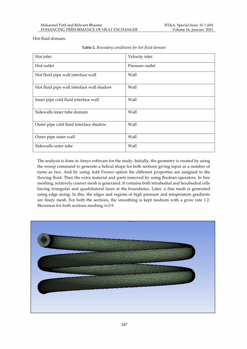
Hot fluid domain:
Table 2. Boundary conditions for hot fluid domain
Hot inlet Velocity inlet
Hot outlet Pressure outlet
Hot fluid pipe wall interface wall Wall
Hot fluid pipe wall interface wall shadow Wall
Inner pipe cold fluid interface wall Wall
Sidewalls inner tube domain Wall
Outer pipe cold fluid interface shadow Wall
Outer pipe outer wall Wall
Sidewalls outer tube Wall
The analysis is done in Ansys software for the study. Initially, the geometry is created by using
the sweep command to generate a helical shape for both sections giving input as a number of
turns as two. And by using Add Frozen option the different properties are assigned to the
flowing fluid. Then the extra material and parts removed by using Boolean operators. In free
meshing, relatively coarser mesh is generated. It contains both tetrahedral and hexahedral cells
having triangular and quadrilateral faces at the boundaries. Later, a fine mesh is generated
using edge sizing. In this, the edges and regions of high pressure and temperature gradients
are finely mesh. For both the sections, the smoothing is kept medium with a grow rate 1.2.
Skewness for both sections meshing is 0.9.

Makarand Patil and Balwant Bhasme ENHANCING PERFORMANCE OF HEAT EXCHANGER
RT&A, Special Issue № 1 (60) Volume 16, Janyary 2021
348
Fig.1 Mesh Model for circular HCHE
Fig.2 Mesh Model for square HCHE
Solver Details:
The governing equations are used are as a continuity equation, energy equation, and momentum
equations. And the k-epsilon model as the flow is turbulent. Pressure velocity coupling is done using
the COUPLED algorithm. Second-order upwind algorithm for pressure and momentum
discretization of these equations while first-order upwind for turbulent kinetic energy and turbulent
dissipation rate. For energy second-order upwind algorithm is used. The convergence criteria are
10-5 for continuity, velocity, k, and epsilon, and that for energy is10-8.
IV. Results and Discussion
In the present CFD investigation, the results are obtained at various curvature ratio, velocity of hot
flowing fluid and outer wall boundary conditions. The simulations are validated by comparing the
results of friction factor for the flow through the helical coil with the numerical and experimental
work done by the researchers.

Makarand Patil and Balwant Bhasme ENHANCING PERFORMANCE OF HEAT EXCHANGER
RT&A, Special Issue № 1 (60) Volume 16, Janyary 2021
349
Fig.3 Comparison of present results with the literature results
Fig-3 shows that the comparison between the present CFD study and the Numerical work done by
Kanungo [1] and experimental work done by Mishra and Gupta [8], Guo [9] for the case of an
insulated outer wall for curvature ratio as 0.1. The points almost lie in the range of data points as
proposed by the researchers. Thus, we can say that present numerical scheme is validated with that
in literatures. To study the heat transfer characteristics of a double pipe helical coil square shape
heat exchanger it is necessary to understand what is the effect of the outer boundary condition of
the thermal properties of the flowing fluid. In this paper to study its effect, four outer wall boundary
conditions as constant heat flux (60000W/m2), constant wall temperature (330K), insulated
condition(q=0W/m2), and outer convective heat transfer coefficient of 4000W/m2K [1] are considered.
Fig.4 Variation of LMTD with velocity for D/d=10 (Square section)
Fig 4, 5, 6 and 7 shows the variation of LMTD with the velocity of the fluid flowing in the inner tube
for four different boundary conditions and curvature ratios 0.1, 0.06, 0.05 and 0.04 respectively. In
this paper, the thermal property considered is temperature. The values of LMTD are calculated by
varying the velocity of inner fluid while the mass flow rate of outer flowing fluid in the outer tube
is kept constant. The results show that the insulated boundary condition gives the maximum value
of LMTD while constant wall temperature has the lowest value among given boundary conditions.
The maximum value of LMTD is 59.59 for the D/d ratio as 10 with inner

Makarand Patil and Balwant Bhasme ENHANCING PERFORMANCE OF HEAT EXCHANGER
RT&A, Special Issue № 1 (60) Volume 16, Janyary 2021
350
Fig.5 Variation of LMTD with velocity for D/d=15 (Square section)
Fig.6 Variation of LMTD with velocity for D/d=20 (Square section)

Makarand Patil and Balwant Bhasme ENHANCING PERFORMANCE OF HEAT EXCHANGER
RT&A, Special Issue № 1 (60) Volume 16, Janyary 2021
351
Fig.7 Variation of LMTD with velocity for D/d=25 (Square section)
fluid velocity as 3.14002m/s. For the curved pipes and channels, the Non-dimensional Dean number
and the Colburn factor plays an important role in the flow and heat transfer characteristics. So, it is
necessary to find an optimum value of curvature ratio by using these two non-dimensional
parameters for the case of constant heat flux and constant wall temperature condition.[1].
Fig.8 Optimum Value for Curvature Ratio for constant heat flux (Square section)
Fig 8 shows the variation of Dean number and Colburn factor with the curvature ratio for the
velocity of 1.25601m/s for constant heat flux boundary condition. As seen from Fig. 8 for both circular

Makarand Patil and Balwant Bhasme ENHANCING PERFORMANCE OF HEAT EXCHANGER
RT&A, Special Issue № 1 (60) Volume 16, Janyary 2021
352
and a squares section with increase in curvature ratio the dean number is increases. While Colburn
factor is the dimensional less quantity which is the product of Stanton number and Prandtl number
is also increases. If the dean number is increases which causes a pair of dean vortices to be stable
which indicates primary dynamic stability. So, to avoid such condition there is a need to find out the
optimum value for the curvature ratio. For the circular section, the optimum value of curvature ratio
for the inner fluid velocity of 1.25601m/s is 0.073 and that for the square section it is 0.093 for constant
heat flux condition. Similarly, the optimum value for curvature ratio is found for circular as well as
a square section for the case of constant wall temperature.
Fig.9 Variation of optimum Value for Curvature Ratio with velocity for constant heat flux
Fig 9 shows the variation of the optimum value of curvature ratio with the velocity of hot fluid
flowing inside the inner tube for both sections for the case of constant heat flux condition. The
optimum value of curvature ratio for both circular and square section increases with an increase in
velocity of fluid flowing inside the inner tube. The maximum value of the optimum curvature ratio
for circular and square section is 0.1 and 0.096 for constant heat flux and that for constant wall
temperature is 0.104 and 0.108. The Fig. 10 is for variation of optimum curvature ratio with a velocity
of hot flowing inside the inner tube for constant wall temperature.
Fig.10 Variation of optimum Value for Curvature Ratio with velocity for constant wall temperature

Makarand Patil and Balwant Bhasme ENHANCING PERFORMANCE OF HEAT EXCHANGER
RT&A, Special Issue № 1 (60) Volume 16, Janyary 2021
353
Not only the velocity of flowing fluid but also the curvature ratio plays an important role in
designing the helical coil heat exchanger. As curvature ratio increases correspondingly the value of
dean number increases which increases in the of pressure drop as seen from fig 11. Also, if the
velocity of flowing hot fluid increases which increases in value of Nusselt number but
correspondingly the value of pressure drop is also increased. An increase in pressure drop causes
an increase in pumping power which increases of cost of the system which is not acceptable. So,
there is a need to find the optimum value of Reynolds number at which we get the maximum Nusselt
number with minimum pumping power which reduces the overall cost of the system. The
intersection of the lines on the graph is the optimum value of Reynolds which gives a high heat
transfer rate for minimum pumping power.
Fig.11 Optimum Value for Reynolds Number for constant heat flux (Square section)
Fig 11 shows the variation of Nusselt Number and Pressure drop with Reynolds number for D/d=15
for the case of constant heat flux condition. Similarly, for the circular and square section for the case
of constant wall temperature is also studied. The maximum value of optimum Reynolds number for
the circular section is 27100 for the D/d ratio as 20 for the square section is 25000 for D/d ratio as 10
and 25.
Fig.12 Variation of Optimum Reynolds number with curvature ratio (Constant heat flux)

Makarand Patil and Balwant Bhasme ENHANCING PERFORMANCE OF HEAT EXCHANGER
RT&A, Special Issue № 1 (60) Volume 16, Janyary 2021
354
Fig 12 shows the variation of the optimum value of Reynolds number with the curvature ratio for
the circular and square section for the constant heat flux condition. The nature of the plot is the same
for both the cross-section. Depending upon the application shape can be chosen. Similarly, for
constant wall temperature is shown in fig 13.
Fig.13 Variation of Optimum Reynolds number with curvature ratio (Constant wall temperature)
The maximum value of the optimum value of Reynolds number for the circular and square
sections is 27800 and 27300 for D/d ratio as 20 and 10 respectively for constant wall temperature.
Like inner flowing fluid velocity, some geometrical parameters affect the heat transfer
characteristics of a double pipe helical coil heat exchanger. So, it is necessary to study the
geometric parameters like the pitch of the coil, tube diameter, number of turns, and the length of
the helical pipe. In this study, the effect of the pitch of the coil on the Nusselt number that is heat
transfer characteristics of the helical coil heat exchanger is studied. The velocity of inner flowing
hot fluid is kept constant and the pitch of the coil is varied by keeping the number of turns as 2.
The height of the helical coil changes according to the pitch of the coil. The curvature ratio is 0.1
and pitch value varied is 20mm, 30mm, 40mm, and 50mm.
Fig. 14 Effect of pitch on Nusselt Number

Makarand Patil and Balwant Bhasme ENHANCING PERFORMANCE OF HEAT EXCHANGER
RT&A, Special Issue № 1 (60) Volume 16, Janyary 2021
355
The Fig 14 shows the variation of Nusselt Number with the pitch of the helical coil. As the length of
the coil is directly proportional to both pitch and number of turns. If the pitch increase by keeping
the height of the helical tube constant the length of the helical tube coil is decreased. The above fig
14. is drawn at inner fluid flowing velocity as 1.25601m/s and keeping the curvature ratio as 0.1 for
both circular and a square section for constant heat flux condition. As the length of the helical coil
decreases the corresponding value of the heat transfer coefficient is decreased. So correspondingly
the value of Nusselt Number decreases as shown in fig 14.
Fig. 15 shows the temperature counter for a velocity of flowing hot fluid as 1.25601m/s for the case
of constant heat flux 60000W/m2K with curvature ratio as 0.1.
Fig. 15 Temperature counter for D/d=10 for V=1.25601m/s for hot outlet
Similarly, the temperature of hot fluid outlet for constant heat flux and for various D/d ratio and
for the various velocity of inner hot fluid is shown in the table 3,
Table. 3 Hot fluid outlet temperature for various D/d ratio and velocities (Constant heat flux)
D/d Velocity of Hot Fluid(m/s) Max. Hot Outlet Temperature
10 1.25601 343.5
15 1.25601 338.9
20 1.25601 334.7
25 1.25601 331
10 1.5072 344.4
15 1.5072 340.1

Makarand Patil and Balwant Bhasme ENHANCING PERFORMANCE OF HEAT EXCHANGER
RT&A, Special Issue № 1 (60) Volume 16, Janyary 2021
356
20 1.5072 336.2
25 1.5072 332.6
10 2.6376 347
15 2.6376 343.7
20 2.6376 340.6
25 2.6376 337.7
10 3.14002 347.7
15 3.14002 344.7
20 3.14002 341.9
25 3.14002 339.2
From the table 3 it has been seen that with an increase in velocity for constant D/d ratio the outlet
temperature of hot fluid increases. Because an increase in velocity of hot flowing fluid the time
available for heat transfer is decreased. In this study the mass flow rate of the cold fluid is kept
constant while, the velocity of hot flowing fluid is varied so, hot fluid flow past the inner tube with
high velocity and not find enough time to transfer heat to cold fluid. The outlet temperature of hot
fluid for D/d=10 is more as compared to others for the same velocity. Similar nature is observed for
both cross-sections for the case of constant wall temperature. The pressure distribution for curvature
ratio 0.1 and for velocity of hot flowing fluid 1.25601m/s for the case of constant heat flux condition
is shown in fig. 16
Fig. 16 Pressure variation D/=10 for V=1.25601m/s (Constant heat flux)

Makarand Patil and Balwant Bhasme ENHANCING PERFORMANCE OF HEAT EXCHANGER
RT&A, Special Issue № 1 (60) Volume 16, Janyary 2021
357
Table.4 Pressure Drop for various D/d ratio and velocities (Constant heat flux)
D/d Velocity of hot fluid(m/s) Pressure Drop
10 1.25601 2652.76
15 1.25601 3154.04
20 1.25601 3791.17
25 1.25601 4475.54
10 1.5072 3660.58
15 1.5072 4336.12
20 1.5072 5204.99
25 1.5072 6141.1
10 2.6376 9849.31
15 2.6376 11617.4
20 2.6376 13879.2
25 2.6376 16399.6
10 3.14002 13599.1
15 3.14002 15833.1
20 3.14002 18883.6
25 3.14002 22213.6
Table.4 shows that the variation of pressure Drop for different D/d ratio and velocity of flowing hot
fluid. With an increase in velocity of hot fluid the pressure Drop increases. When the flow is more
turbulent more energy is lost due to the conversion of pressure energy to kinetic energy. With an
increase in D/d ratio pressure loss increases because increase in D/d ratio the length of pipe increases
and with an increase in length losses are more. Similar nature is to observe for the circular sections
and both sections for constant wall temperature.
V. Conclusion
Numerical simulation has been carried out for tube in tube helical coil heat exchanger with coil shape
as both circular and a square section for the various boundary conditions. Boundary conditions used
was constant heat flux, constant wall temperature, insulated wall and wall applied with heat transfer
coefficient of 4000 W/m2K. Curvature ratio, LMTD, Friction factor, Pressure drop parameters are are
studied. It can be seen from the LMTD results the insulated boundary condition gives the highest
heat transfer while; the constant wall temperature condition gives the minimum heat transfer among
given boundary conditions. In present investigation the optimum curvature ratio is found for
various velocities of inner fluid for constant heat flux and constant wall temperature outer wall
conditions. It is found that for both of these conditions the optimum value of the curvature ratio for
circular as well as square section first decreases and then increases with an increase in velocity of
inner fluid. It can also be concluded from present study that with an increase in the pitch of the
helical coil by keeping the height of the helical coil tube constant, heat transfer increases

Makarand Patil and Balwant Bhasme ENHANCING PERFORMANCE OF HEAT EXCHANGER
RT&A, Special Issue № 1 (60) Volume 16, Janyary 2021
358
References
[1] Kanungo “Numerical analysis to optimise the heat transfer rate of tube-in-tube helical coil
heat exchanger” PhD Thesis Dept. of Mechanical engineering NIT Rourkela-2014.
[2] Jayakumar J.S, Mahajani S.M., Mandal J.C, Iyer Kannan N., and Vijayan P.K., “CFD analysis
of single-phase flows inside helically coiled tubes”, Computers, and Chemical Engineering, 34 (2010)
pp.430–446.
[3] Ashok B. Korane, P.S. Purandare, K.V. Mali, “Heat transfer analysis of Helical coil heat
exchanger with circular and square coiled pattern” IJESR, Vol-2, issue-6, (2012).
[4] Kharat Rahul., Bhardwaj Nitin., Jha R.S., “Development of heat transfer coefficient
correlation for concentric helical coil heat exchanger”, International Journal of Thermal Sciences,
vol.-48 (2009) pp 2300–2308.
[5] Rennie Timothy J. and Raghavan Vijaya G.S., “Numerical studies of a double-pipe helical
heat exchanger”, Applied Thermal Engineering, vol.-26 (2006) pp 1266–1273.
[6] Triloki Nath Mishra, “Modelling and CFD Analysis of Tube in Tube Helical Coil Heat
Exchanger”, International Journal of Science and Research, vol 4. (8), (2015) pp 1536-1541
[7] Aly Wael I.A., “Numerical study on turbulent heat transfer and pressure drop of nanofluid
in coiled tube-in tube heat exchangers”, Energy Conversion and Management, vol.- 79, (2014)
pp.304–316.
[8] Mishra, P., and Gupta, S. N., 1979, “Momentum Transfer in Curved Pipes: Newtonian
Fluids,” Ind. Eng. Chem. Des. Dev., 18, pp. 130–137.
[9] Bai, B., Guo, L., Feng, Z. and Chen, X. “Turbulent heat transfer in a horizontally coiled tube”.
Heat Transfer Asian Res, vol-28, pp.395–403(1999).