effect of supporting structure design on residual stresses
TRANSCRIPT

Effect of supporting structure design on residualstresses in selective laser melting of AlSi10MgXiaohui Jiang ( [email protected] )
University of Shanghai for Science and TechnologyChunbo Yu
University of Shanghai for Science and TechnologyHonglan Guo
University of Shanghai for Science and TechnologyShan Gao
Shanghai Aircraft Manufacturing Company LimitedYong Zhang
University of Shanghai for Science and Technology
Research Article
Keywords: SLM, Residual stress, Finite element analysis, Supporting structure
Posted Date: April 30th, 2021
DOI: https://doi.org/10.21203/rs.3.rs-471475/v1
License: This work is licensed under a Creative Commons Attribution 4.0 International License. Read Full License

*Dr. Xiaohui Jiang
University of Shanghai for Science & Technology, Shanghai 200093 China. Tel: +86 15121029145, E-mail: [email protected]
1
Effect of supporting structure design on residual stresses in selective
laser melting of AlSi10Mg
Jiang Xiaohui1, Yu Chunbo1, Guo Honglan1, Gao Shan2, Zhang Yong1
(1. College of Mechanical Engineering, University of Shanghai for Science and
Technology, Shanghai 200093, China
2. Shanghai Aircraft Manufacturing Company Limited, China)
Abstract:Residual stress is a key indicator to measure the forming quality of SLM components, and its
control method has received extensive attention. As an auxiliary structure for forming SLM components,
the structural characteristics of the supporting structure will affect the residual stress distribution of the
formed parts. Therefore, it is extremely meaningful to explore the influence of the supporting structure
design on the residual stress of SLM AlSi10Mg alloy. In this study, an approach is proposed to select and
design the support structure for forming SLM components with different structural characteristics to
achieve the purpose of reducing the residual stress in the overhanging structure of the components. As
the result shows, when the contact area of single supporting tooth structure and component overhanging
structure is 0.25mm2 and the X/Y interval of main supporting structure is 2.5mm, the forming effect is
relatively good. Furthermore, the block supporting structure is more suitable for the overhanging
structure which has small areas and less height, and the contour support is more suitable for the
overhanging structure with larger area.
Keywords:SLM; Residual stress; Finite element analysis; Supporting structure
1. Introduction
In recent years, as an emerging manufacturing technology, additive manufacturing (AM) technology has great developing potential in the global manufacturing industry, which has gained wide concentration. [1-3] Selective laser melting (SLM) is a typical additive manufacturing technology, the technology uses a laser heat source to melt metal powder to form a cladding layer and solidify it by heat dissipation into a high-performance metal part with a complex three-dimensional structure. [4] Selective laser melted component has good mechanical properties such as strength of extension, elongation, Young’s modulus, impact toughness and hardness. [5] Although SLM technology has many great advantages in precise parts of complex form, the unbalanced temperature distribution and the inability to exert local thermal effects result in high residual stress inside the SLM part due to the concentrated energy and high power of the laser, resulting in uneven expansion and contraction of the material on the powder bed, and high residual stresses inside the

2
SLM part after solidification and cooling. [6-7] Residual stresses in components may lead to warping, cracking and reducing mechanical strength of the part, therefore, the analysis of residual stresses in SLM is a necessary aspect to ensure reliable part quality, it is influenced by SLM process parameters and supporting structure, etc. [8-9] Consequently, select suitable SLM parameters and design special supporting structures to reduce the residual stresses in metal parts to improve the surface quality and forming efficiency of the parts.
On the basis studies of the SLM process parameters on residual stress, many scholars have developed thermodynamic models from the SLM process perspective and explored the effects of process parameters such as laser heat source, powder thickness and scanning speed, with the aim of improving the performance of SLM alloys. [10-12] In the early days, some researchers used finite element simulations to calculate the temperature field distribution near the laser spot in the SLM process and pointed out that a large temperature gradient would have a negative effect, but did not calculate the stress field. [13] Based on the thermo-elasticity theory, a thermo-dynamic coupling model was established in the SLM process, and the thermal and residual stress in the heat-affected zone was calculated. [14] Yadroitsev I et al. [15] studied the residual stresses in stainless steel 316 L and Ti6Al4V alloy parts using numerical simulations and X-ray diffraction techniques. Zaeh M F et al. [16] Increased the thickness of the powder layer by a factor of 2.5 reduced the deformation at the end of the T-shaped cantilever by 82%. Wang L F et al. [17] studied the residual stresses in SLM AISi10Mg alloy with different scanning strategies and preheating temperatures as a way to improve the performance of SLM parts. As a way to improve the performance of SLM parts, the optimization of SLM process parameters can greatly enhance the microstructure and mechanical properties of the parts.
On the basis studies of the supporting structures on residual stress, many scholars have considered the forming angle of supporting structure and the direction of the component with the reduction of the supporting structures, aiming to improve the performance of SLM alloy and forming efficiency. [18-20] SLM components with overhanging structural features often require additional supporting structures to assist in forming to limit curling or deformation during the forming process, and after forming, further post-treatment through heat treatment is required to reduce residual stress. [21] Byun H S et al. [22] applied a weighted approach to optimize the molding direction multi-objective problem with the component surface roughness as optimization objectives. Zhang Z X et al. [23] designed a group of standard candidates of branch support structures for SLM and compared the weight and scanning time of specimens with different design parameters to study the influence of different support parameters on mechanical strength of the support structures. Gaynor A T et al. [24] proposed a topology optimization component that can design the smallest speech supporting angle. Strano G and Hao L et al. [25] used Gyroid and Diamond equations to generate supporting structures, and proposed a method of using different sizes of Gyroid and Diamond equations to different supporting features. Jhabvala J and Boillat E et al. [26] reduced the production time of the supporting structure by using different types of lasers, which can speed up the production of the supporting structure. Therefore, geometric design and optimization of the supporting structure can improve the quality and efficiency of SLM formed parts.
From the above discussion, it can be found that most scholars have carried out basic research and theoretical analysis from SLM process parameters to achieve the purpose of improving the quality of SLM formed components, but there are still many problems in designing supporting structures. Therefore, based on the characteristics of overhanging structure of the SLM metal

3
component this study establishes the finite element models, select the suitable laser heat source models and heat transfer models, design different supporting structures, then use the simulation software to solve and analyze. The design of supporting structures includes the contact surface area between the supporting tooth structure and the overhanging structure of the part, the density distribution of the supporting body structure and the selections different hybrid supporting structure types. The residual stress of the formed parts was tested experimentally and the simulation results were compared to verify the reasonableness of the simulation results.
2. Methodology
2.1 Materials
SLM is a rapid manufacturing technology, in SLM forming, the material will melt from the initial powder state into a liquid state, and then condense into a solid state after cooling and heat transfer. Therefore, the physical properties of the metal powder, such as particle size, fluidity and packing density, will have a direct impact on the surface quality and shape accuracy of the SLM formed parts. [27]
In this study, the material used, AlSi10Mg alloy, is a widely used casting aluminum alloy, after modification and heat treatment, it has good corrosion resistance and mechanical properties as well as excellent molding effect and can be used in fields such as aerospace engine parts, ship structure parts and instrument parts. [28] In this study, the sample shown in Fig. 1(d) was formed by SLM, which is a thin-walled bracket in first level of aerospace inter-box with a surface dimension specification of 196mm*178mm*49mm, the width of the overhanging structure of its upper wing plate is 20mm, and the wall thickness of the thinnest part of the component is 1.5mm. The material uses an aerosolized AlSi10Mg alloy powder with an average particle size of up to 40um and spherical particles. The material composition and mechanical properties of AlSi10Mg are listed in Tables 1, 2, respectively.
Table 1 Chemical compositions of AlSi10Mg aluminum alloy powder Element Si Mg Cu Fe Mn Zn Al
Composition(wt-%) 10.4 0.6 0.06 0.2 0.03 0.01 Balance
Table 2 Mechanical properties of AlSi10Mg
Parameter Young's modulus Yield strength Tensile strength Poisson's ration
Value 70GPa 251MPa 396MPa 0.32
2.2 Experiment Steps
The SLM equipment used in this experiment is the SPACE M200 SLM manufacturing system, as shown in Fig. 1(a), the forming size of equipment is 250*250*250mm, and the comprehensive mechanical properties of the formed components reach the standard of homogeneous forgings. Fig. 1 (b) shows the inner cavity of SPACE M200 forming equipment. In this study, the relevant SLM parameters for the forming process are shown in Table 3, a basic block supporting structure was adopted to assist the forming of selective laser melting samples, and the residual stresses were measured by X-ray diffraction after forming. The Tec4000 equipment was used for the measurement of residual stresses, as shown in Figure 1(c). The formed sample was placed on the measurement platform of the X-ray diffraction instrument, since the sample is a symmetric body, so one long side and two short sides of the sample overhanging structure were selected for the measurement at seven symmetry points, and the way of measurement is shown in Fig. 1(e).

4
Fig. 1 (a)The SLM manufacturing system. (b)Residual stress test. (c)sample. (d)Test point distribution
Table 3 SLM process parameters Process parameters Value
Laser power (W) 300
Scanning speed (mm/s) 200
Power layer thickness (um) 50
Scanning spacing (um) 150
Preheating temperature (℃) 160
Scanning strategy Checkerboard scanning
Support structure Basic block support
2.3 Modelling
2.3.1 Heat source model Heat source model has a great influence on the calculation and analysis of the temperature
field and stress in the SLM process. Improper selection of heat source model can lead to great deviation between the calculated result and the actual result. [29] The heat source models include the Gauss heat source model, the double-ellipse heat source model and combined heat source model. Considering that the YLR-500-SM single-mode fiber laser is used in this experiment, the laser

5
energy is more consistent with the Gauss distribution, and its energy distribution equation is as follows: [30]
2
2 2
2 2AP rQ exp
R R
= −
(1)
Where 𝐴 is the thermal absorption rate of the laser beam on the metal powder, which determines an important parameter of the energy input of the whole heat source. Its size is related to the material temperature, laser wavelength, incident angle, powder particle size, loose packing density and powder space stacking method and other factors; 𝑃 is the heat source laser power; 𝑅 is the radius of the effective laser spot; 𝑟 is the distance from a point on the powder bed to the center of the spot.
2.3.2 Heat transfer model SLM is a rapid manufacturing technology which uses the laser heat source energy to make
the localized powder on powder bed melting rapidly, as the laser moves away, the melt pool solidified to form the cladding layer, and finally formed by cooling. In the process, a lot of heat generated in the system will make the powder occur a phase transition between liquid and solid state, the thermal problem is determined by the enthalpy of the system, the enthalpy of the system can be defined as follows: [31]
0
T
pT
H c dT= (2)
Where 𝜌 is the density and 𝑐𝑃 is the specific heat capacity of the powder material. In the system, the laser heat source energy acts on the powder bed through the form of heat
flow, and only a part of the laser energy is absorbed in the process, the rest is reflected. Most of the energy absorbed by the material enters the powder bed through the form of heat conduction, and the rest is consumed in the form of thermal convection and thermal radiation, etc. These thermal mechanisms are coupled and determine the temperature field distribution within the material, and the heat transfer within the system is determined by the heat transfer control equation within the system volume 𝑉, the thermal equation can be defined as follows:
( )( ) V S
Hk T T Q Q ,in V
t
= + +
(3)
where 𝑄𝑉 is the volumetric heat flux, which is the heat input from the laser heat source defined by equation (1); 𝑄𝑆 is the surface heat flux, which is the heat generated by thermal radiation on the exposed powder bed surface 𝑆, whose size is determined by the thermal radiation emissivity and temperature change of the material. As the forming height ℎ increases, the surface heat flux 𝑄𝑆 can be defined as follows:
( ) ( ) ( )4 4
0 0 0 S c
TQ k T h T T T T ,on dS
h
= = − + −
(4)
where k is the thermal conductivity, 𝑇0 is the ambient temperature, ℎ𝑐 is the thermal convection coefficient, 𝜀 is the thermal radiation emissivity of metal powder and solid, and its magnitude varies with temperature as shown in Fig. 2, 𝜎0 is the Stefan-Boltzmann constant, whose magnitude 5.67x10⁻⁸W/m2K4.

6
Fig. 2 The temperature-heat radiation emissivity value of AlSi10Mg powders and solids
3. Support design
The supporting structure is divided into the support tooth part and the supporting body part, and the supporting body part is the main part of the supporting structure, as shown in Fig. 3. The basic supporting structure mainly includes point support, line support, block support and mesh support, etc. Although these basic supporting structures satisfy the role of supporting the forming of the overhanging structure, the forming components have some deficiencies in quality, and at the same time, the waste of supporting materials and low forming efficiency are not considered. Therefore, it is very particularly meaningful to explore the effects of the design of supporting structure for SLM components.
In this study, different designs for the supporting tooth, supporting body and hybrid supporting types were carried out, and the designed supporting structure is used to assist the formation of the SLM components. The study was carried out in terms of the effects on contact area between the support tooth and the overhanging structure, the X/Y interval of the supporting body and the selection of different hybrid supporting types on the quality of the formed components. The simulation analysis of the auxiliary forming process is carried out according to the different designed supporting structures.
Fig. 3 Basic parameters of support structure
3.1 Design of support tooth structure
As a structure connecting the overhanging structure of components and the supporting body, the tooth support can not only provide support for the forming of the overhanging structure, but also provide heat conduction during the SLM process. A suitable contact method can not only provide
7
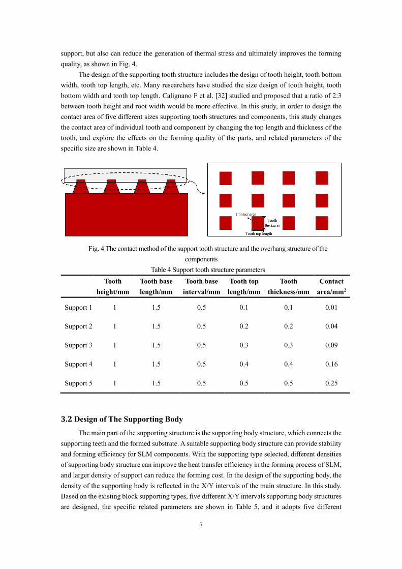
support, but also can reduce the generation of thermal stress and ultimately improves the forming quality, as shown in Fig. 4.
The design of the supporting tooth structure includes the design of tooth height, tooth bottom width, tooth top length, etc. Many researchers have studied the size design of tooth height, tooth bottom width and tooth top length. Calignano F et al. [32] studied and proposed that a ratio of 2:3 between tooth height and root width would be more effective. In this study, in order to design the contact area of five different sizes supporting tooth structures and components, this study changes the contact area of individual tooth and component by changing the top length and thickness of the tooth, and explore the effects on the forming quality of the parts, and related parameters of the specific size are shown in Table 4.
Fig. 4 The contact method of the support tooth structure and the overhang structure of the components
Table 4 Support tooth structure parameters Tooth
height/mm
Tooth base length/mm
Tooth base interval/mm
Tooth top length/mm
Tooth thickness/mm
Contact area/mm2
Support 1 1 1.5 0.5 0.1 0.1 0.01
Support 2 1 1.5 0.5 0.2 0.2 0.04
Support 3 1 1.5 0.5 0.3 0.3 0.09
Support 4 1 1.5 0.5 0.4 0.4 0.16
Support 5 1 1.5 0.5 0.5 0.5 0.25
3.2 Design of The Supporting Body
The main part of the supporting structure is the supporting body structure, which connects the supporting teeth and the formed substrate. A suitable supporting body structure can provide stability and forming efficiency for SLM components. With the supporting type selected, different densities of supporting body structure can improve the heat transfer efficiency in the forming process of SLM, and larger density of support can reduce the forming cost. In the design of the supporting body, the density of the supporting body is reflected in the X/Y intervals of the main structure. In this study. Based on the existing block supporting types, five different X/Y intervals supporting body structures are designed, the specific related parameters are shown in Table 5, and it adopts five different

8
supporting body structures to assist the SLM forming of aerospace components, and analyzes the influence of the support body structures with different X/Y intervals on the quality of the formed components.
Table 5 support main structure parameters
Support parameters Support structure
Support body X/Y intervals/mm
1,1.5,2,2.5,3
Support tooth contact area/mm2
0.25
Type of support structure
Block support
3.3 Selection of Hybrid Supporting Type
During the SLM forming, if the component is formed directly on metal substrate of the powder bed, and then it needs to use wire cutting to get the component, this process will affect the surface quality of the component. Therefore, a basic supporting structure is needed to assist in the forming of the bottom of the component. For the structural forming of large planar features, the temperature field will be affected due to the short distance between two adjacent scans for the forming of the block supporting structure, and the stability of the cone support is poor, so it usually uses the contour support to assist in forming, the selection of the overhanging structure support of the component should be determined by its forming quality. In this study, contour support was chosen to assist in forming the bottom of the component, and block support, entity support and cone support were used to assist in forming the overhanging structure respectively, as shown in Fig. 5. The contact area of the supporting tooth is selected as 0.25mm2, and the X/Y interval of the support body is selected as 2.5mm, and then analyze the effects of different hybrid supporting types on the forming quality of the components respectively.
Fig. 5 Hybrid support types. (a)Contour-Block support structure. (b) Contour-Entity support structure. (c) Contour-Cone support structure
4. Results and Discussions
4.1 Mechanism of Residual Stress Formation in Overhanging Structures in SLM
The formation of the targeted component in the SLM is formed by rapidly heating the AlSi10Mg metal powder on the powder bed from a powder state to a liquid phase to form a cladding layer, and finally cooling and solidifying into a solid phase. The initial state of the material is powder,

9
which is relatively loose and its stress is zero. After a certain phase transition, the stress state will change accordingly, as shown in Fig. 6. The powder material in the local area where the laser heat source acts on the powder bed heats up rapidly due to the energy of the heat source, and a molten pool with a certain temperature gradient is formed in this area from top to bottom. The formation of the molten pool will lead to uneven expansion and contraction of the material. The upper surface of the material will expand by heat, resulting in strain 𝜀𝑇, but its expansion will be limited by the surrounding forming area, resulting in a compressive stress 𝜎𝑐 acting on the boundary of the molten pool. After the laser heat source sweeps this area, the temperature drops rapidly and enters the cooling and solidification stage. The upper surface of the material shrinks and is limited by the surrounding forming area to generate tensile stress 𝜎𝑇, which accumulates and eventually leads to the formation of residual stress on the component.
Fig. 6 The mechanism of residual stress during the SLM process Take the SLM forming simulation of the part with the process parameters in Table 3, and
collect the residual stress values in the X direction and Y direction of the corresponding position, and compare it with the experimental measurement results. Through analysis, the simulation analysis results match well with the experimental results, and the average error rate is about 11.2%, which verifies the feasibility of the simulation model. As shown in Fig. 7, the residual stress distribution of the part overhanging structure is obviously related to the position, and it can be found that the residual stress in the X-direction is larger in the long side of the part overhanging structure, and the residual stress in the Y-direction in the short side of the part overhang structure is larger than that of the long side. The agreement between experimental and simulation values also shows that the simulation model can be used for calculations related to residual stress, other discussions content is illustrated by numerical simulation results.
Fig. 7 Comparison of experimental results and simulation results of residual stress. (a) X-Residual stress. (b) Y-Residual stress

10
4.2 Effect of contact area between supporting tooth on the residual stress of
overhanging structure
In the SLM forming process, the supporting tooth part is the part that directly contacts with the overhanging structure of the component, and the size of its contact area will affect the stability of the supporting structure and the heat transfer efficiency of the forming process directly. Within the permitted range, as the contact area of a single tooth increases, its heat transfer efficiency increases, which can be used as an important factor in controlling residual stress. Fig. 8 are field cloud pictures of the residual stress field in the X and Y directions of the component under the five different contact areas of the supporting tooth designed in Table 4. It can be found that the residual stress in the component is mainly tensile stress, and there is a larger residual stress in the X direction at the middle of the long side of the overhanging structure of the component, and the residual stress in the X direction at the edge of the long side of the overhanging structure is smaller, averaging 90 to 140 MPa. The higher stress in the middle area of the overhanging structure is due to the increase in heat density input in this area during the SLM process, resulting in a larger temperature gradient, and uneven expansion and contraction of the material, which significantly increases the stress of the component. There is a larger residual stress in the Y-direction at the edge of the short side of the overhanging structure, which indicates that the residual stress in the Y-direction plays a dominant role in the residual stress at the short side of the overhanging structure of the formed part during the SLM process.
Fig. 8 Residual stress field nephograms with different support tooth contact areas. (a, f) Support 1. (b, g) Support 2. (c, h) Support 3. (d, i) Support 4. (e, j) Support 5
Fig. 9 is the distribution of residual stress in X and Y directions of the component overhanging structure corresponding to the measured points under different contact areas of the supporting tooth. When the contact area between a single supporting tooth and the overhanging structure is 0.01 mm2, the highest residual stress in X direction of the overhanging structure reaches 197 MPa and the highest residual stress in Y direction reaches 237 MPa, which is a large stress state and may lead to defects such as warping of the part. As the contact area was increased from 0.01mm2 to 0.25mm2, the X-direction residual stress was reduced by an average of 24.4% and the maximum residual stress was reduced by 27.3%, the Y-direction residual stress was reduced by an average of 26.1% and the maximum residual stress was reduced by 22.7%. Because in the process of SLM, with enlargement of the contact area between the supporting structure and the overhanging structure, the heat transfer efficiency increases, the cooling rate of the melt pool increases, and the uneven expansion and contraction of the material is less, which lead to greatly reduction of the residual stress on the overhanging surface.

11
Fig. 9 Residual stress distribution in different support tooth contact areas. (a) X-Residual stress. (b) Y-Residual stress
4.3 Effect of X/Y interval of support body on the residual stress of overhanging
structure
The key of the supporting structure is the supporting body part, which connects the supporting tooth with the forming substrate. Different densities of supporting body structure can improve the heat transfer efficiency of the forming process and reduce a certain cost under the premise of ensuring supporting stability. In SLM forming process, the change of stress depends on the change of melting pool in forming and is determined by the efficiency of heat transfer in forming process. The basic ways of heat transfer are heat conduction, heat convection and heat radiation. In the SLM process of AlSi10Mg alloy, the way of heat transfer is mainly heat conduction, and the heat transfer effect of the supporting structure of the supporting body with different X/Y intervals. In order to ensure the supporting stability within the range of supporting structure density, five different X/Y intervals of supporting body structures are designed, the related parameters are shown in Table 5. Five different supporting body structures are used to support the aerospace component forming simulation, and fig. 10 are the residual stress distribution field cloud pictures of the component overhanging structure in X and Y directions under different X/Y intervals of supporting body.
Fig. 10 Residual stress field nephograms with different support main structure X/Y distances. (a, f) 3mm. (b, g) 2.5mm. (c, h) 2mm. (d, i) 1.5mm. (e, j) 1mm
Fig. 11 is the distribution of residual stress in X and Y directions of the component overhanging structure corresponding to the measured points under different supporting body X/Y intervals, and it can be found that the residual stresses in the X and Y directions are in the range of

12
100 to 170 MPa on the long side of the component overhanging structure, and the residual stress in the Y direction on the short side plays a major role. When the X/Y interval of the supporting body is 3mm, the maximum residual stress of the overhanging structure in the X direction reaches 171MPa and the maximum residual stress in the Y direction reaches 239MPa, the stress state may cause problems such as warping, deformation or even cracking of the component. The comparison results show that when the X/Y interval size is reduced from 3 mm to 1.5 mm, the residual stress in the X direction is reduced by 13.4% and the maximum residual stress is reduced by 16.9% on average, and the residual stress in the Y direction is reduced by 12.2% and the maximum residual stress is reduced by 12.6% on average. Because the X/Y interval of the supporting body becomes smaller and the supporting density increases accordingly, the heat conduction efficiency increases, and the uneven expansion and contraction becomes smaller, which leads to the residual stress value of the overhanging structure of the component is greatly reduced. When the X/Y interval is reduced from 1.5mm to 1mm again, the average stress is only reduced by 0.64% and the use of supporting material is increased by 2.25 times; in view of the quality and light-weight consideration of structure, the most optimized distance of X/Y interval is 1.5mm.
Fig. 11 Residual stress distribution in different support main structure X/Y distances. (a) X-Residual stress. (b) Y-Residual stress
4.4 Effect of Hybrid Supporting Structure Type on Residual Stresses of
Overhanging Structure
The selection of supporting structure types is determined by the structural characteristics of the SLM formed component overhanging structure. Different types of supporting structures need to be selected to improve the residual stress for different size of overhanging structures, which can achieve the goal of reducing the deformation and improving the quality of the SLM formed component on the premise of meeting the strength of the supporting structure. Fig. 12 shows the distribution of residual stresses in the X and Y directions for overhanging structure of the SLM formed component with different combinations of supporting types in fig. 5. It can be found that the residual stress in the overhanging structure are mainly tensile stresses, and the X-direction residual stress in the middle part of the long side overhanging structure are significantly higher than the residual stress on both sides of the long side.

13
Fig.12 Residual stress distribution in different hybrid support types. (a) X-Residual stress. (b) Y-Residual stress
Different selections of supporting structure types for components will have different effects, when the contour-cone supporting structure is selected, the residual stresses in the X-direction along the surface of the component overhanging structure are about 18.6% and 19.2% higher than those in the contour-block and contour-entity supporting structures. The residual stresses in the Y-direction are about 7.2% and 13.5% higher than those in the contour-block and contour-solid supporting structures. Because the cone-shaped supporting structure is narrow in the upper part and wide in the lower part, and the overhanging structure of this component requires a higher supporting structure, the heat transfer effect is much lower than that of the contour-block and contour-entity type supporting structures, resulting in the temperature accumulation and thermal expansion of the surface of the component during forming, the residual stress is largest. And when entity support forming is chosen for the overhanging structure, the residual stresses on the surface of the SLM formed component in the X-direction and in the Y-direction are only 0.6% and 6.3% lower than the block supporting structure, but the volume of the entity supporting structure is about 2.5 times the volume of the block support, it means the amount of its powder material used needs to be 2.5 times accordingly. It can be found that, considering the surface quality of the formed components and the light-weight of the structure, it is more suitable for the SLM forming of the components to choose the contour supporting structure for the bottom surface and the block supporting structure for the overhanging structure.
5. Conclusion
The design of the supporting structure is of great importance for SLM components. In this study, a is proposed based on a combination of numerical simulations and conventional experiments for the analysis of residual stress in components with overhanging structures. The main conclusions are as follows.
1. The generation and variation of stress in SLM-formed components is caused by the temperature gradient of the melt pool on the powder bed. The residual stress in the overhanging structure of the SLM component calculated by numerical simulation matches well with the experimental results, with an average error rate of about 11.2%.
2. Under the premise of ensuring the stiffness of the supporting structure and the surface quality of the components after removing the support, the increase of the contact area between the supporting tooth structure and the overhanging structure can greatly reduce the residual stress of the overhanging structure. The suitable contact area between a single supporting tooth and the

14
overhanging structure is 0.25mm2, which can reduce the residual stress in X direction by 24.4% and in Y direction by 26.1%.
3. Under the premise of ensuring the stability of the supporting structure, the appropriate increase in the density of the supporting body structure can reduce the residual stress of the overhanging structure of SLM-formed components. Taking into account the light-weight of the supporting body structure, the suitable X/Y interval of the supporting body structure is 2.5mm, the residual stress in the X direction can be reduced by 13.4%, and the residual stress in the Y direction can be reduced by 12.3%.
4. Different types of hybrid supporting structures need to be selected for the overhanging structures of SLM components with different area sizes. Contour support is generally chosen for forming the bottom surface of a component. Block supports should be selected for overhanging structures with small areas and heights, and contour supports can be selected for overhanging structures with larger areas.
Acknowledge
Funding information
This project is supported by Shanghai Science and Technology Commission (Grant No.20ZR1438000)
Ethical Approval Compliance with ethical standards.
Consent to Participate and Publish
Conflict of interest The authors declare that they have no conflict of interest.
Authors Contributions Jiang Xiaohui: Conceptualization, Methodology, Supervision. Yu Chunbo: Data curation, Validation, Writing- Original draft preparation. Guo Honglan: Experimental assit. Gao Shan: Visualization. Zhang Yong: Investigation
Availability of data and materials The data and materials that support the findings of this study are available from the corresponding author upon reasonable request.
References
1. Mishra AK, Aggarwal A, Kumar A, Sinha N. (2018) Identification of a suitable volumetric
heat source for modelling of selective laser melting of Ti6Al4V powder using numerical and
experimental validation approach. International Journal of Advanced Manufacturing
Technology 99(9-12):2257-2270
2. Zhang H, Xu W, Xu YJ, Lu ZL, Li DC. (2018) The thermal-mechanical behavior of
WTaMoNb high-entropy alloy via selective laser melting (SLM): experiment and simulation.
International Journal of Advanced Manufacturing Technology 96(1-4):461-474
3. Wang LF, Jiang XH, Guo MX, Zhu XG, Yan B. (2017) Characterisation of structural

15
properties for AlSi10Mg alloys fabricated by selective laser melting. Journal of Materials
Science and Technology 33(18):2274-2282
4. Ali H, Ghadbeigi H, Mumtaz K. (2018) Effect of scanning strategies on residual stress and
mechanical properties of selective laser melted Ti6Al4V. Materials Science and Engineering
A-Structural Materials Properties Microstructure and Processing 712:175-187
5. Song CH, Yang YQ, Liu Y. (2015) Study on manufacturing of W-Cu alloy thin wall parts
by selective laser melting. International Journal of Advanced Manufacturing Technology 78(5-
8):885-893
6. Salmi A, Atzeni E. (2017) History of residual stresses during the production phases of
AlSi10Mg parts processed by powder bed additive manufacturing technology. Virtual and
Physical Prototyping 12(12):1–8
7. Lenders S, Thone M, Riemer A, Niendorf T, Troster T, Richard HA, Maier HJ. (2013) On
the mechanical behaviour of titanium alloy TiAl6V4 manufactured by selective laser melting:
Fatigue resistance and crack growth performance. International Journal of Fatigue 48:300-307
8. Liu Y, Yang YQ, Wang D. (2016) A study on the residual stress during selective laser
melting (SLM) of metallic powder. International Journal of Advanced Manufacturing
Technology 87(1-4):647-656
9. Kempen K, Thijs L, Van Humbeeck J, Kruth JP. (2015) Processing AlSi10Mg
by selective laser melting: parameter optimisation and material characterisation. Materials
Science and Technology 31(8):917-923
10. Jiang XH, Xiong WJ, Wang LF, Guo MX, Ding ZS. (2020) Heat treatment effects on
microstructure-residual stress for selective laser melting AlSi10Mg. Materials Science and
Technology 36(2):168-180
11. Wang WL, He L, Yang X, Wang D. (2021) Research on the formation process of selective
laser melting Mg-Y-Sm-Zn-Zr alloy. Materials Science and Technology 37(2):174-181
12. Morgan HD, Cherry JA, Jonnalagadda S, Ewing D, Sienz J. (2016) Part orientation
optimisation for the additive layer manufacture of metal components. International Journal of
Advanced Manufacturing Technology 86(5-8):1679-1687
13. Roberts IA, Wang CJ, Esterlein R, Stanford M, Mynors DJ. (2009) A three-dimensional
finite element analysis of the temperature field during laser melting of metal powders in
additive layer manufacturing. International Journal of Machine Tools&Manufacture 49(12-
13):916-923
14. Hussein A, Hao L, Yan CZ, Everson R. (2013) Finite element simulation of the temperature
and stress fields in single layers built without-support in selective laser melting. Materials&
Design 52:638-647
15. Yadroitsev I, Yadroitsava I. (2015) Evaluation of residual stress in stainless steel 316L and
Ti6Al4V samples produced by selective laser melting. Virtual and Physical Prototyping
10(2):67-76
16. Zeah M.F, Branner G. (2010) Investigations on Residual Stresses and Deformations in
Selective Laser Melting. Production Engineering 4(1):35-45
17. Wang LF, Jiang XH, Zhu YH, Ding ZS, Zhu XG, Sun J, Yan B. (2018) Investigation of
performance and residual stress generation of AlSi10Mg processed by selective laser melting.
Advances in Materials Science and Engineering 1-12: https://doi.org/10.1155/2018/7814039
18. Li ZH, Zhang DZ, Peng D, Kucukkoc L. (2017) A lightweight and support-free design

16
method for selective laser melting. International Journal of Advanced Manufacturing
Technology 90(9-12):2943-2953
19. Wang D, Yang YQ, Yi ZH, Sun XB. (2013) Research on the fabricating quality
optimization of the overhanging surface in SLM process. International Journal of Advanced
Manufacturing Technology 65(9-12):1471-1484
20. Calignano F. (2014) Design optimization of supports for overhanging structures in
aluminum and titanium alloys by selective laser melting. Materials&Design 64:203-213
21. Kruth JP, Levy G, Klocke F, Childs THC. (2007) Consolidation phenomena in laser and
powder-bed based layered manufacturing. Cirp Annals-Manufacturing Technology 56(2):730-
759
22. Byun HS, Lee KH. (2006) Determination of the optimal build direction for different rapid
prototyping processes using multi-criterion decision making. Robotics and Computer-
Integrated Manufacturing 22(1):69-80
23. Zhang ZX, Wu CB, Li T, Liang KS, Cao YJ. (2018) Design of internal branch support
structures for selective laser melting. Rapid Prototyping Journal 24(4):764-773:
https://doi.org/10.1108/RPJ-11-2016-0186
24. Gaynor AT, Guest JK. (2016) Topology optimization considering overhang constraints:
Eliminating sacrificial support material in additive manufacturing through design. Structural
and Multidisciplinary Optimization 54(5): 1157-1172
25. Strano G, Hao L, Everson RM, Evans KE. (2013) A new approach to the design and
optimisation of support structures in additive manufacturing. International Journal of Advanced
Manufacturing Technology 66(9-12): 1247-1254
26. Jhabvala J, Boillat E, Andre C, Glardon R. An innovative method to build support structures
with a pulsed laser in the selective laser melting process. International Journal of Advanced
Manufacturing Technology 59(1-4): 137-142
27. Kadirgama, K.1, Harun W.S.W.1, Tarlochan M.1, Ramasamy D.1, Azir M.Z.1, Mehboob
H.2. (2018) Statistical and optimize of lattice structures with selective laser melting (SLM) of
Ti6AL4V material. International Journal of Advanced Manufacturing Technology 97(1-4):495-
510
28. Jiang XH, Ye T, Zhu YH. (2019) Effect of process parameters on residual stress in selective
laser melting of AlSi10Mg. Materials Science and Technology 36(3):342-352
29. Wang LF, Jiang XH, Zhu YH, Zhu XG, Sun J, Yan B. (2018) An approach to predict the
residual stress and distortion during the selective laser melting of AlSi10Mg parts. International
Journal of Advanced Manufacturing Technology 97(9-12):3535-3546
30. Yin J, Zhu HH, Ke LD, Lei WJ, Dai C, Zuo DL. (2012) Simulation of temperature
distribution in single metallic powder layer for laser micro-sintering. Computational Materials
Science 53(1):333-339
31. Parry L, Ashcroft IA, Wildman RD. (2016) Understanding the effect of laser scan strategy
on residual stress in selective laser melting through thermo-mechanical Simulation. Additive
Manufacturing 12:1-15
32. Calignano F. (2014) Design optimization of supports for overhanging structures in
aluminum and titanium alloys by selective laser melting. Materials&Design 64:203-213

Figures
Figure 1
(a)The SLM manufacturing system. (b)Residual stress test. (c)sample. (d)Test point distribution
Figure 2

The temperature-heat radiation emissivity value of AlSi10Mg powders and solids
Figure 3
Basic parameters of support structure
Figure 4
The contact method of the support tooth structure and the overhang structure of the components
Figure 5
Hybrid support types. (a)Contour-Block support structure. (b) Contour-Entity support structure. (c)Contour-Cone support structure
Figure 6
The mechanism of residual stress during the SLM process

Figure 7
Comparison of experimental results and simulation results of residual stress. (a) X-Residual stress. (b) Y-Residual stress
Figure 8
Residual stress �eld nephograms with different support tooth contact areas. (a, f) Support 1. (b, g)Support 2. (c, h) Support 3. (d, i) Support 4. (e, j) Support 5
Figure 9

Residual stress distribution in different support tooth contact areas. (a) X-Residual stress. (b) Y-Residualstress
Figure 10
Residual stress �eld nephograms with different support main structure X/Y distances. (a, f) 3mm. (b, g)2.5mm. (c, h) 2mm. (d, i) 1.5mm. (e, j) 1mm
Figure 11
Residual stress distribution in different support main structure X/Y distances. (a) X-Residual stress. (b) Y-Residual stress
Figure 12

Residual stress distribution in different hybrid support types. (a) X-Residual stress. (b) Y-Residual stress