effect of residual stress on cleavage fracture toughness...
TRANSCRIPT
doi: 10.1111/j.1460-2695.2011.01550.x
Effect of residual stress on cleavage fracture toughness by usingcohesive zone model
X. B . REN 1, Z . L . ZHANG 1 and B. NYHUS 2
1Department of Structural Engineering, Norwegian University of Science and Technology (NTNU), N-7491, Trondheim, Norway, 2SINTEFMaterials and Chemistry, N-7465 Trondheim, Norway
Received in final form 13 Dec 2010
A B S T R A C T This study presents the effect of residual stresses on cleavage fracture toughness by usingthe cohesive zone model under mode I, plane stain conditions. Modified boundary layersimulations were performed with the remote boundary conditions governed by the elasticK-field and T-stress. The eigenstrain method was used to introduce residual stresses intothe finite element model. A layer of cohesive elements was deployed ahead of the cracktip to simulate the fracture process zone. A bilinear traction–separation-law was used tocharacterize the behaviour of the cohesive elements. It was assumed that the initiation ofthe crack occurs when the opening stress drops to zero at the first integration point of thefirst cohesive element ahead of the crack tip. Results show that tensile residual stresses candecrease the cleavage fracture toughness significantly. The effect of the weld zone size oncleavage fracture toughness was also investigated, and it has been found that the initiationtoughness is the linear function of the size of the geometrically similar weld. Results alsoshow that the effect of the residual stress is stronger for negative T-stress while its effect isrelatively smaller for positive T-stress. The influence of damage parameters and materialhardening was also studied.
Keywords cleavage toughness; cohesive zone model; eigenstrain method; modifiedboundary layer model; residual stress.
I N T R O D U C T I O N
Residual stresses associated with welding are unavoidableand play an important role in structural integrity of engi-neering components. It has been shown that the residualstresses influence both the crack driving force1 and crack-tip constraint.2–4 Crack-tip constraint arises from differ-ences in the level of opening stress near the crack tip andaffects the transferability of material toughness, which isa key issue in application of fracture mechanics to assessthe integrity of structural components.5 Cleavage fracturefeatured with negligible plastic tearing before final failureis often the most dangerous failure mode. It occurs by theunstable propagation of microcracks formed within grainboundary particles by twinning or slip dislocation pile-upsand then grows into the ferrite matrix under the action oftensile stress.6 The cleavage fracture toughness exhibitssensitivity to the local stress and deformation fields due to
Correspondence: Z. L. Zhang. E-mail: [email protected]
its highly localized character of the failure mechanism.5
Understanding how residual stresses influence the cleav-age fracture behaviour becomes more and more impor-tant when high-strength steels are increasingly utilized inoffshore industry.
Experimental work undertaken by Mirzaee-Sisan et al.7
indicated an apparent reduction in mean cleavage fracturetoughness of an A553-B ferritic steel of 50% from con-ventional fracture toughness data due to residual stresses.Panontin and Hill6 utilized the Ritchie–Knott–Rice(RKR)8 model to predict the effect of residual stresseson brittle fracture initiation and found that the constraintgenerated by the residual stress decreases the initiationtoughness of brittle fracture.
Micromechanical models using continuum representa-tion of stress and strain are generally used to predict lo-cal conditions for cleavage fracture. For cleavage fractureto happen, the opening stress should reach the criticalvalue σ c at a certain distance from the crack tip rc orwithin a certain volume in front of the crack tip.9 This
592 c© 2011 Blackwell Publishing Ltd. Fatigue Fract Engng Mater Struct 34, 592–603
Fatigue & Fracture of Engineering Materials & Structures

RESBr i t t le 593
physical scale must be considered in studying the mi-cromechanisms of fracture in order to consider mi-crostructural features necessary for the physical failuremechanism. It was assumed in the RKR model that occur-rence of cleavage fracture requires that the opening stressσ 22 at the crack tip exceeds the fracture stress σ ∗
f over acritical distance l∗b which is on the order of the grain sizeof the steel. Previous studies concerning cleavage fractureindicate that the critical fracture stress ranges from threeto four times the yield strength of the material, and thatis relatively independent of temperature and strain rate.Estimates of the characteristic length or distance in mildsteels range from 2 to 5 grain diameters.6 However, in realelastic–plastic materials, large plastic deformations are of-ten necessary to initiate the cleavage fracture. Therefore,Neimitz et al.9 proposed an alternative formulation of theRKR criterion. The cleavage fracture was demonstratedas a synergistic action of the stress and deformation atthe critical moment. It has been demonstrated that forfracture to occur it is not sufficient that the opening stressreaches the critical value alone, but it is also necessary thatthe location of this maximum from the crack tip must beover the distance l ≥ lc, where lc is considered as a materialparameter.
The current study investigated the effect of the residualstresses on the cleavage fracture toughness by employinga modified boundary layer (MBL) model under mode Iplane strain conditions with the remote boundary gov-erned by elastic K-field and T-stress. The cohesive zonemodel was utilized to simulate the cleavage fracture, andthe failure was assumed to occur when the opening stressat the first integration point of the first cohesive elementahead of the crack tip drops to zero, as illustrated in Fig. 1.The assumption is based on the modified RKR criterionproposed by Neimitz et al.,9 and the large strain effect wasalso considered in the analyses. Based on this assumption,the effect of the residual stresses on cleavage toughnesswas investigated by comparing the case including residualstress effect with the reference case.
N U M E R I C A L P R O C E D U R E
Problem description
This study concerns an ideal problem. A large roundcylinder with a weld in the centre was studied. The cylin-der was simulated by a 2D plane strain MBL model withthe remote boundary governed by the elastic K-field andT-stress. The analysis procedure consists of the followingsteps: (1) enforce a welding procedure, which introducea residual stress field; (2) introduce a sharp crack; (3) ap-ply the external load, as illustrated in Fig. 2. It shouldbe noted that the contact between the upper and lowerfree surfaces were considered when the residual stress was
Fig. 1 Schematic plot of the assumption made in this study.
introduced. The cohesive zone model was used to modelthe fracture process zone (FPZ). The material propertymismatch between the weld metal and base metal has notbeen taken into account.
Finite element model
The MBL model used for this study consists of a weldregion located in the centre of the model and an outerbase metal region, and a sharp crack was embedded in thecentre of weld. The load was applied to the remote edgesof the model through a displacement field (u, v) governedby the elastic asymptotic stress field of a plane strain modeI crack:
u(r, θ ) = KI1 + v
E
√r
2πcos
(12θ
)(3 − 4v − cos θ )
+T1 − v2
Er cos θ
v(r, θ ) = KI1 + v
E
√r
2πsin
(12θ
)(3 − 4v − cos θ )
−Tv(1 + v)
Er sin θ,
(1)
where KI =√
E J/1 − v2 under plane strain condition,E is Young’s modulus, ν is Poisson’s ratio, and r and θ
are polar coordinates centred at the crack tip with θ = 0corresponding to the crack tip.
The finite element computations were performed usingABAQUS.10 The radius of the MBL model was taken as200 mm. A layer of uniform-sized cohesive elements wasdeployed along the central line ahead of the crack tip tosimulate the fracture process. The length of the cohesiveelement-layer is 20 mm, and the size of the uniform co-hesive element lc is 0.1 mm. The thickness of the cohesiveelements is 2.5 × 10⁻⁴ mm. The weld metal and base metalregion of the model was meshed by standard full integra-tion four-node 2D plane strain elements. The cohesiveelements are standard cohesive element COH2D4. Thefinite element model has 4992 elements and the meshesare shown in Fig. 3.
c© 2011 Blackwell Publishing Ltd. Fatigue Fract Engng Mater Struct 34, 592–603
594 X. B . REN et al.
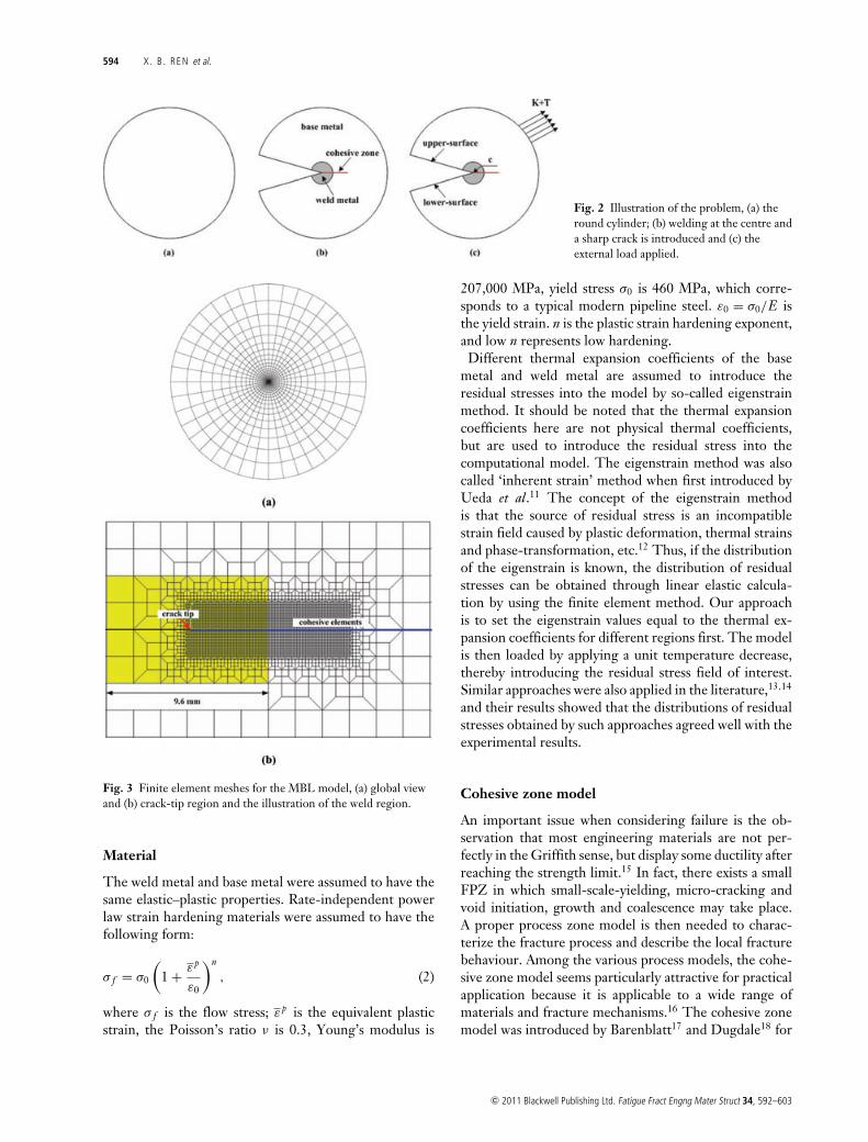
Fig. 2 Illustration of the problem, (a) theround cylinder; (b) welding at the centre anda sharp crack is introduced and (c) theexternal load applied.
Fig. 3 Finite element meshes for the MBL model, (a) global viewand (b) crack-tip region and the illustration of the weld region.
Material
The weld metal and base metal were assumed to have thesame elastic–plastic properties. Rate-independent powerlaw strain hardening materials were assumed to have thefollowing form:
σ f = σ0
(1 + ε p
ε0
)n
, (2)
where σ f is the flow stress; ε p is the equivalent plasticstrain, the Poisson’s ratio ν is 0.3, Young’s modulus is
207,000 MPa, yield stress σ0 is 460 MPa, which corre-sponds to a typical modern pipeline steel. ε0 = σ0/E isthe yield strain. n is the plastic strain hardening exponent,and low n represents low hardening.
Different thermal expansion coefficients of the basemetal and weld metal are assumed to introduce theresidual stresses into the model by so-called eigenstrainmethod. It should be noted that the thermal expansioncoefficients here are not physical thermal coefficients,but are used to introduce the residual stress into thecomputational model. The eigenstrain method was alsocalled ‘inherent strain’ method when first introduced byUeda et al.11 The concept of the eigenstrain methodis that the source of residual stress is an incompatiblestrain field caused by plastic deformation, thermal strainsand phase-transformation, etc.12 Thus, if the distributionof the eigenstrain is known, the distribution of residualstresses can be obtained through linear elastic calcula-tion by using the finite element method. Our approachis to set the eigenstrain values equal to the thermal ex-pansion coefficients for different regions first. The modelis then loaded by applying a unit temperature decrease,thereby introducing the residual stress field of interest.Similar approaches were also applied in the literature,13,14
and their results showed that the distributions of residualstresses obtained by such approaches agreed well with theexperimental results.
Cohesive zone model
An important issue when considering failure is the ob-servation that most engineering materials are not per-fectly in the Griffith sense, but display some ductility afterreaching the strength limit.15 In fact, there exists a smallFPZ in which small-scale-yielding, micro-cracking andvoid initiation, growth and coalescence may take place.A proper process zone model is then needed to charac-terize the fracture process and describe the local fracturebehaviour. Among the various process models, the cohe-sive zone model seems particularly attractive for practicalapplication because it is applicable to a wide range ofmaterials and fracture mechanisms.16 The cohesive zonemodel was introduced by Barenblatt17 and Dugdale18 for
c© 2011 Blackwell Publishing Ltd. Fatigue Fract Engng Mater Struct 34, 592–603
RESBr i t t le 595
Fig. 4 Schematic plot of the TSL used in the analysis.
elastic–plastic fracture in ductile metals and for quasi-brittle materials by Hillerborg et al.19 under the name offictitious crack model.
The fundamental concept of the cohesive zone modelis a so-called traction–separation law (TSL), which is afunction described by the cohesive stress (σ ) and separa-tion (δ).20 The area under the traction–separation relationrepresents the cohesive energy �0. The basic parametersnecessary to describe the TSL are two among the criticaltraction σ max, the critical separation δc and the cohesiveenergy �0.
21
One of the key problems in the application of the co-hesive zone model is the choice of the TSL within thecohesive zone. Needleman first proposed a polynomiallaw,22 and later an exponential law was introduced by Xuand Needleman.23 Tvergaard and Hutchinson21 proposeda trapezoidal law for ductile fracture. The TSL used inthis paper is a bilinear relationship between the tractionand the separation, as shown in Fig. 4, which is charac-teristic of brittle materials.16 The dominant parametersare cohesive energy �0 and the maximum cohesive stressσ max.
When a cohesive zone model is employed to simulatethe cracking behaviour of a brittle thin interface, the soft-ening part of the TSL may cause some problems to thesolution algorithm. A snap-back instability can occur de-pending on interface thickness, stiffness and the length ofthe elements adjacent to the cohesive zone.24 If a discon-tinuity of the response occurs, the simulation can stop.A possible solution is the viscous regularization methodproposed by Chaboche et al.24 which consists in intro-ducing a fictitious viscosity parameter in the constitutiveequation of the cohesive elements. In turn, the conver-gence of the solution can be achieved by dissipating excessenergy; but the value of the viscosity parameter shouldbe small enough to not affect the results. Pezzotta andZhang25 demonstrated that when the viscosity value v≤ 1.0E-5 the predicted failure becomes independent ofthe viscosity parameter when other parameters are fixed.Thus, the value was used for all the calculations in thisstudy.
R E S U L T S A N D D I S C U S S I O N
Cleavage fracture toughness exhibits a strong sensitiv-ity to the local stress and deformation fields due to itshighly localized character. Residual stresses affect boththe crack driving forces and crack tip constraint,1,3,4,6
which may further influence the cleavage fracture tough-ness. Therefore, the effect of residual stresses on cleavagefracture toughness was investigated in this study. Thecontour J-integral26 was utilized as the measure of thecleavage fracture toughness. Lei et al.1 and Lei27 showedthat the J-integral shows path-dependence with the pres-ence of the residual stresses. In our study, the computedfar-field J-integral by ABAQUS shows practically path-independence beyond the large strain region for the casesinvestigated. The J-integral in the following means thecalculated J-integral.
Residual stress fields
As described before, we used the eigenstrain method tointroduce residual stresses into the finite element model.A rectangular weld region was constructed in the centreof the MBL model, as illustrated in Fig. 3. The thermalexpansion coefficient of the base metal αb was assumed tobe zero, and it was assumed to be orthogonal and repre-sented by α11 and α22 for weld metal. The ratio α11/α22
was fixed to be 2, and by setting α22 = –0.0005, 0.0005,0.001 and 0.002, four residual stress fields were generatedand designated as RsField0, RsField1, RsField2 and Rs-Field3, respectively, as shown in Fig. 5. It should be notedthat the eigenstrain values selected here are taken fromthe experimental measurement results in literature.28,29
The residual stress fields generated by these values havesimilar distribution to that shown in Ref. [30]. To obtainaccurate distribution of the residual stress fields by eigen-strain method, one should carry out the experiments tomeasure the distribution of the eigenstrain. However, themain objective of this study is to investigate the effect ofthe residual stresses; the prediction of the real distributionof the residual stress field is outside the scope. Note thatthe stress components are normalized by the yield stress,and the distance from the crack tip x is normalized by thesize of the uniform element size lc.
It can be seen that the negative eigenstrain value intro-duces the compressive residual stress at the weld regionwhile the positive ones generate tensile residual stresses.Both tensile and compressive residual stresses parallel tothe crack front converge to zero far from the crack tip.The opening residual stresses are self-balanced ahead ofthe crack tip. There is a sharp turning point in the dis-tribution of the opening residual stresses, which is theregion where eigenstrain discontinuities have been intro-duced into the FE model, namely a weld metal–base metal
c© 2011 Blackwell Publishing Ltd. Fatigue Fract Engng Mater Struct 34, 592–603

596 X. B . REN et al.
Fig. 5 Residual stress distributions in the MBL model, (a) stresscomponent parallel to the crack plane; (b) normal to the crackplane. Four different residual stress cases were considered, whereRsField0 is compressive and the remaining three are tensile.α11/ α22 = 2, α22 = −0.0005 is for RsField0, α22 = 0.0005, 0.001and 0.002 for RsField1, RsField2 and Rsfield3, respectively.
boundary. The tensile residual stresses also show similar-ity, and the level of the tensile residual stress increaseswith the increase of α22. Due to the crack-tip singularity,σ 11 is about 960 MPa and σ 22 is about 1380 MPa at thecrack tip for RsField3.
Effect of residual stresses on cleavage fracturetoughness
Cleavage fracture is a crucial failure mode in practice, andunderstanding how residual stresses affect the cleavagefracture is very important. The effect of residual stresses,as shown in Fig. 5, on cleavage fracture toughness was in-vestigated in this section. Cohesive parameters �0 = 100
Fig. 6 Cleavage toughness as the function of the crack growthlength when the incremental plasticity model is used forsurrounding materials. E/σ 0 = 450, ν = 0.3; n = 0.1; �0 =100 N/mm, σmax = 3σ 0.
N/mm were selected and the maximum cohesive stressσ max was set to be 3σ 0. The cleavage toughness was plot-ted as the function of crack growth length in Fig. 6.
It can be seen that the crack growth resistances are al-most flat for both with and without residual stress cases.Figure 6 also indicates that the cohesive zone model withbilinear TSL is applicable to predict the cleavage fracturetoughness. In the following context, the initiation frac-ture toughness (Jc) predicted according to the assumptionmade in first section will be investigated. Residual stressesmay influence both the FPZ and plasticity of surroundingmaterials. Therefore, three different constitutive models,i.e. incremental plasticity, deformation plasticity and elas-tic, were employed to characterize different behaviour ofsurrounding materials. The relationship between JC andthe eigenstrain value α22 is shown in Fig. 7. It should benoted that α22 = 0 represents the reference case withoutresidual stresses.
As shown in Fig. 7, the compressive residual stress (α22
< 0) increases the cleavage fracture toughness while thetensile residual stresses decrease the cleavage fracturetoughness. With the increase of tensile residual stress,the cleavage fracture toughness decreases. Also observethat the effect of residual stress on fracture toughnessis almost the same for elastic and deformation plastic-ity surrounding materials. However, the cleavage fracturetoughness for surrounding materials predicted with incre-mental plasticity is significantly larger than in other cases.When the surrounding material is elastic or character-ized by deformation plasticity model, the cleavage frac-ture toughness without residual stress (α22 = 0) equalsto cohesive energy �0, which represents energy neededto advance the crack in the absence of plasticity. For
c© 2011 Blackwell Publishing Ltd. Fatigue Fract Engng Mater Struct 34, 592–603
RESBr i t t le 597
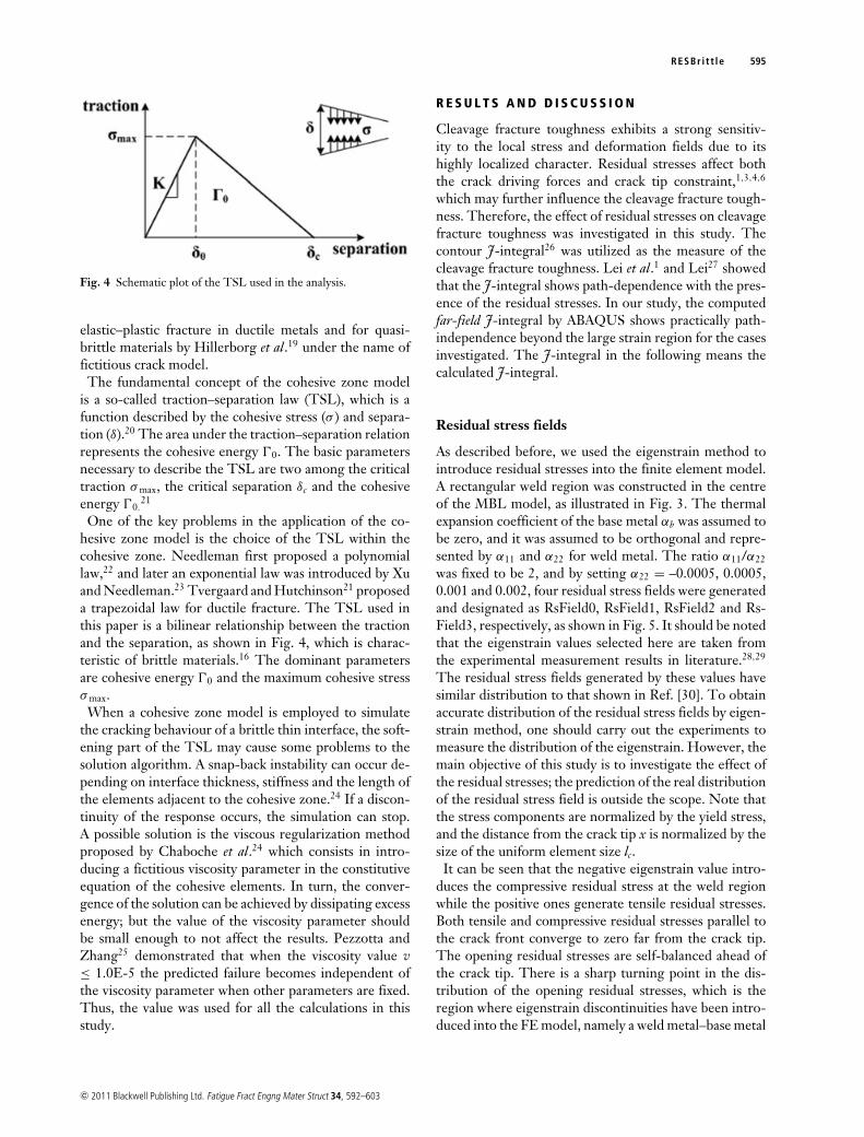
Fig. 7 Cleavage fracture toughness as the function of α22. n = 0.1;�0 = 100 N/mm, σmax = 3σ 0.
Fig. 8 Plasticity contributions from the surrounding materials atthe crack initiation. n = 0.1; �0 = 100 N/mm, σmax = 3σ 0.
incremental plasticity material model, it can be seen thatcleavage fracture toughness is larger than 1. For elasticand deformation plasticity model, the deformation canreturn back to the original state when the load is re-moved. However, when an incremental plasticity modelis used and unloading occurs, the plastic deformationwill be retained and the energy will be dissipated, whichin turn increases the fracture toughness. In the follow-ing, the incremental plasticity model has been used forthe study. In order to better understand the contribu-tion of plasticity of surrounding material, the effect ofdifferent σ 0 on cleavage fracture toughness in the ab-sence of residual stresses was investigated. Figure 8 showsthe relationship between cleavage fracture toughness andσ 0/E.
It can be seen that with the increase of yield stress, thecleavage fracture toughness decreases and approaches to
Fig. 9 Plastic zone size for εp = 1% at the crack initiation, and theincremental plasticity model is used for surrounding materials.E/σ 0 = 450, ν = 0.3; n = 0.1; �0 = 100 N/mm, σmax = 3σ 0.
�0, which indicates the decreasing of the plastic zonesize of surrounding materials. When residual stress ispresent, it may influence the plastic deformation of thesurrounding materials. Figure 9 shows the plastic zonesize when cleavage fracture occurs for different residualstresses.
Figure 9 shows that the compressive residual stress field,i.e. RsField0, both enlarges the maximum radius of theplastic zone and causes plastic zone to swing forward.In contrast, tensile residual stress fields cause the plas-tic zone to decrease in size and rotate backward. Similarbehaviour has been reported by Du and Hancock31 whoinvestigated the effect of T-stress on the crack-tip con-straint. Negative T-stress indicates loss of the crack-tipconstraint while the positive T-stress has the opposite ef-fect. Thus, we may conclude that the compressive residualstress reduces the crack-tip constraint and enlarges theplastic zone, which in turn enhances the cleavage fracturetoughness significantly. Unlike the compressive resid-ual stress, tensile residual stresses increased the crack-tipconstraint and reduced the cleavage toughness.
Effect of weld zone size on cleavage fracturetoughness
The length scale of residual stress field may play an im-portant role on the effect of residual stress on cleavagefracture toughness. To better demonstrate this, three ge-ometrically similar rectangular weld regions were con-structed, as shown in Fig. 10. The size of the weld isdesignated as c. Eigenstrain values α11 = 0.004 and α22
= 0.002 have been used to generate residual stress fieldfor all welds. Residual stress fields represented by Size1,Size2 and Size3, respectively, are shown in Fig. 11, inwhich residual stresses are normalized by the yield stressand the distance from the crack tip is normalized by lc.Residual stresses are tensile in the weld metal and showsimilar feature as the previous residual stresses showed in
c© 2011 Blackwell Publishing Ltd. Fatigue Fract Engng Mater Struct 34, 592–603

598 X. B . REN et al.
Fig. 10 Schematic plot of different weld zone sizes considered inthe study.
Fig. 5. With the increase of the weld zone size, residualstress components parallel to the crack plane increases,and the size of the tensile-dominated region of openingstress also increases.
Figure 12 shows that the cleavage fracture toughness de-creases with the increase of the weld region size c, whichcan be expected because both the residual stress level andtensile-dominated residual stress region increases with theincrease of the weld zone size. Furthermore, it is interest-ing to observe that the relationship between the cleavagefracture toughness and the weld zone size can be fitted bya linear function, i.e. y = –0.05432x + 1.409, which canpossibly be used to predict the effect of residual stress onthe cleavage fracture toughness for geometrically similarwelds.
Effect of residual stresses on cleavage fracturetoughness for different hardening
In this study, the effect of the residual stress on the cleav-age fracture toughness was investigated for three harden-ing exponents, i.e. n = 0.05, 0.1 and 0.2. Residual stressfield with α11 = 0.004 and α22 = 0.002, i.e. RsField3,was introduced for study. The relationship between thecleavage fracture toughness and the hardening exponentfor both with and without residual stress is showed inFig. 13, and the difference between two curves representsthe effect of residual stress.
As shown in Fig. 13, the existence of residual stress re-duces the cleavage fracture toughness for all the casesanalysed. However, the effect of the residual stress de-creases with the increase of material hardening. As isknown, fully developed plastic zone is easier to be achieved
Fig. 11 Residual stress distributions in the MBL model fordifferent weld zone sizes, (a) components parallel to the crackplane, and (b) normal to the crack plane. lc is the uniform elementsize close to the crack tip. E/σ 0 = 450, ν = 0.3; n = 0.1; �0 =100 N/mm, σmax = 3σ 0; α11 = 0.004, α22 = 0.002.
for weaker hardening material. Hence, the effect of plasticdissipation becomes significant, and a larger reduction ofthe cleavage fracture toughness can be expected.
Effect of damage parameters
The cohesive energy �0 and the maximum cohesive stressσ max are two dominant parameters of the TSL. The effectof the residual stress on the cleavage fracture toughnessmay vary for different cohesive zone parameters. In thisstudy, we firstly investigated the effect of the residualstress on the cleavage fracture toughness for different �0
with the same σ max, and then for the same �0 with dif-ferent σ max. Residual stress field with α11 = 0.004 andα22 = 0.002, i.e. RsField3, was introduced for the study.Figure 14 shows the comparison of the cleavage fracture
c© 2011 Blackwell Publishing Ltd. Fatigue Fract Engng Mater Struct 34, 592–603

RESBr i t t le 599
Fig. 12 Effect of weld zone size on cleavage fracture toughness.E/σ 0 = 450, ν = 0.3; n = 0.1; �0 = 100 N/mm, σmax = 3σ 0; α11 =0.004, α22 = 0.002.
Fig. 13 Effect of residual stress on cleavage fracture toughness fordifferent hardening. E/σ 0 = 450, ν = 0.3; �0 = 100 N/mm, σmax =3σ 0; α11 = 0.004, α22 = 0.002.
toughness Jc for both with and without residual stress asthe function of cohesive energy.
It can be seen that with the increase of the cohesive en-ergy �0, the cleavage fracture toughness increases for bothwith and without residual stresses, as shown in Fig. 14a.Figure 14b shows that the normalized cleavage fracturetoughness tends to converge to the case without residualstress with increasing �0. Note that the cleavage frac-ture toughness with residual stress was normalized by thetoughness without residual stress effect. Figure 15 showsthe effect of the residual stress on the plastic zone for dif-ferent �0, and the length of the FPZ, which measures thedistance between the point where all traction is lost andwhere the peak stress is first attained.21
Fig. 14 Relationship between the fracture toughness and cohesiveenergy, (a) absolute difference between the case with and withoutresidual stress, and (b) normalized values. E/σ 0 = 450, ν = 0.3; n =0.1; σmax = 3σ 0; α11 = 0.004, α22 = 0.002.
As shown in Fig. 15a the residual stress increases thelength of FPZ when �0 < 150 N/mm, beyond which theresidual stress does not affect the FPZ for the cases stud-ied. However, the tensile residual stress both reduces thesize of the plastic zone and rotates the plastic zone back-ward for all �0, as shown in Fig. 15b. We can also observethat with the increase of �0, the plastic zone size increasesfor both with and without residual stress cases, which canexplain the increasing cleavage fracture toughness showedin Fig. 14a.
The maximum cohesive stress is an another importantparameter in cohesive zone model. In the present study,the effect of residual stress on the cleavage fracture tough-ness for three maximum cohesive stresses, i.e. σ max/σ 0 =2.8, 3.0 and 3.3, was studied. Residual stress field withα11 = 0.004 and α22 = 0.002, i.e. RsField3, was used.
c© 2011 Blackwell Publishing Ltd. Fatigue Fract Engng Mater Struct 34, 592–603

600 X. B . REN et al.
Fig. 15 Effect of the residual stress on (a)the length of FPZ, and (b) plastic zone sizeof the surrounding materials for εp = 1%.For each cohesive energy case, the left plotof plastic zone is the case without residualstress and the right one shows the case withresidual stress. E/σ 0 = 450, ν = 0.3; n = 0.1;σmax = 3σ 0; α11 = 0.004, α22 = 0.002.
Fig. 16 Cleavage fracture toughness as a function of maximumcohesive stress for both with and without residual stress cases. E/σ 0= 450, ν = 0.3; n = 0.1; �0 = 100 N/mm; α11 = 0.004, α22 = 0.002.
Cohesive energy �0 was fixed to be 100 N/mm. The rela-tionship between the cleavage fracture toughness and themaximum cohesive stress is showed in Fig. 16.
It can be seen that with the increase of σ max, the reduc-tion of cleavage fracture toughness due to residual stress
increases. When the maximum cohesive stress is smaller,the energy needed to initiate a crack is less, and a fully de-veloped plastic zone cannot be formed. It has been shownthat plastic dissipation only becomes significant comparedto �0 when fully developed plastic zone can form.21 Thus,a stronger effect of residual stress on the cleavage fracturetoughness can be expected for higher σ max.
Effect of applied T-stress
In this study, no real structural component was consid-ered. It is thus interesting to investigate the effect of resid-ual stress on the cleavage fracture toughness for differentgeometry constraint levels characterized by T-stress. Theouter boundary condition for the MBL model is governedby the elastic K-field and a T-stress under small-scale-yielding condition. For mode I loading, K is the amplitudeof the singular stress field, while the T is a non-singularstress term, acting parallel to the crack plane. Geometryconstraint effects on fracture behaviour can be investi-gated by utilizing the T-stress.32 In the current study, T-stress with the value of T/σ 0 = –0.5, –0.25, 0 and 0.5 wasstudied. The same residual stress field as previous withα11 = 0.004 and α22 = 0.002, i.e. RsField3, was used. The
c© 2011 Blackwell Publishing Ltd. Fatigue Fract Engng Mater Struct 34, 592–603

RESBr i t t le 601
Fig. 17 Effect of residual stresses on the cleavage fracturetoughness for different T/σ 0. E/σ 0 = 450, ν = 0.3; n = 0.1; �0 =100 N/mm, σmax = 3σ 0; α11 = 0.004, α22 = 0.002.
Fig. 18 Effect of residual stress on size of plastic zone for differentgeometry constraint when εp = 1% at crack initiation. N representsthe case without residual stress and W denotes the case withresidual stress. E/σ 0 = 450, ν = 0.3; n = 0.1; �0 = 100 N/mm,σmax = 3σ 0; α11 = 0.004, α22 = 0.002.
cleavage fracture toughness was plotted as the function ofT/σ 0 in Fig. 17.
It can be seen that with the increase of the T-stress, thecleavage fracture toughness decreases for both with andwithout residual stresses. As expected, with the increase ofthe T-stress the crack-tip constraint increases and thus theplastic zone shrinks. Similar results were also reported byTvergaard and Hutchinson33 in their study on the effectof T-stress on mode I crack growth resistance in a ductilesolid. It is interesting to observe that with the increaseof the T-stress the effect of the residual stress decreases.Figure 18 shows the effect of the residual stress on plasticzone size for different T-stress.
It can be seen that the negative T-stress enlarges theplastic zone. However, the presence of tensile residualstress significantly decreases the size of the plastic zoneand rotates the plastic zone backward slightly. The pos-itive T-stress shrinks the plastic zone, and the residualstress further rotates the plastic zone backward. We thuscan conclude that the tensile residual stress influences thecleavage fracture toughness similar way as the positiveT-stress.
C O N C L U S I O N S
In this paper the effect of residual stresses on cleavagefracture toughness has been investigated. The damagemechanics-based cohesive zone model was utilized tosimulate the FPZ. The MBL model simulations wereperformed under mode I, plane strain conditions, andthe remote boundary conditions of the model is gov-erned by elastic K-field and T-stress. Residual stresseswere introduced into the FE model by the eigenstrainmethod. Cleavage fracture was assumed to occur when theopening stress of the first integration point of the first co-hesive element ahead of the crack tip dropped to zero.Far-field contour J-integral has been employed to quan-tify the cleavage fracture toughness.
Cohesive zone model with a bilinear TSL was employedto study the effect of residual stresses on cleavage fracturebehaviour. The introduction of a small fictitious viscosityin the TSL in combination with the use of a small step-increment in the simulations improved the convergencerate, and its effect on the results is negligible.
Results show that residual stresses affect both the lengthof the FPZ and surrounding material plasticity. Localcompressive residual stress enhances the cleavage frac-ture toughness while positive residual stresses have oppo-site influences. The compressive residual stress enlargesthe plastic zone significantly while tensile residual stressesshrink the plastic zone and rotate the plastic zone back-ward. When the welds are geometrically similar, the effectof residual stresses on the cleavage fracture toughness isa linear function of the size of the weld. The dominantcohesive parameters �0 and σ max also play an importantrole on the effect of residual stresses on the cleavage frac-ture toughness. With the increase of cohesive energy, theeffect of residual stresses on the cleavage toughness de-creases. The reduction of the toughness caused by resid-ual stresses increases with the increase of the maximumcohesive stress.
The effect of residual stresses on the cleavage fracturetoughness becomes weaker for higher geometry con-straint configuration. It has been found that residualstresses show similar behaviour as the T-stress. When com-bining the residual stresses with T-stress, the superpositionprinciple can be applied. For higher geometry constraint
c© 2011 Blackwell Publishing Ltd. Fatigue Fract Engng Mater Struct 34, 592–603

602 X. B . REN et al.
configuration, the effect of tensile residual stress becomessmaller. However, for lower geometry constraint case, thecombined effect can induce a significant reduction of thecleavage fracture toughness.
Though wide range of parameters have been investi-gated in this paper, the contribution of plasticity fromthe surrounding materials and component geometry con-straint are believed to play a dominant role in the effectof residual stresses on the cleavage fracture toughness.Further experimental verification will be of interest infuture.
Acknowledgements
The funding from the Research Council of Norwaythrough the ‘STORFORSK’ project No.167397/V30 isgreatly acknowledged. The first author would like to ac-knowledge Dr. Erling Østby and Dr. Sigmund Kyrre Asof SINTEF Materials and Chemistry, Dr. Junhua Zhaoand Dr. Junyan Liu of Norwegian University of Sci-ence and Technology, for their valuable comments anddiscussions.
R E F E R E N C E S
1 Lei, Y., O’dowd, N.P. and Webster, G. (2000) Fracturemechanics analysis of a crack in a residual stress field. Int. J.Fract. 106, 195–216.
2 Xu, W. and Burdekin, F. (1998) Effects of residual stresses onconstraint and fracture behaviour of wide plates. Proc.: Math.Phys. Eng. Sci. 454, 2505–2528.
3 Liu, J., Zhang, Z.L. and Nyhus, B. (2008) Residual stressinduced crack tip constraint. Eng. Fract. Mech. 75, 4151–4166.
4 Ren, X.B., Zhang, Z.L. and Nyhus, B. (2009) Effect ofresidual stresses on the crack-tip constraint in a modifiedboundary layer model. Int. J. Solids Struct. 46, 2629–2641.
5 Gao, X. and Dodds, Jr. R. (2001) An engineering approach toassess constraint effects on cleavage fracture toughness. Eng.Fract. Mech. 68, 263–283.
6 Panontin, T. and Hill, M. (1996) The effect of residualstresses on brittle and ductile fracture initiation predicted bymicromechanical models. Int. J. Fract. 82,317–333.
7 Mirzaee-Sisan, A., Truman, C., Smith, D. and Smith, M.(2007) Interaction of residual stress with mechanical loadingin a ferritic steel. Eng. Fract. Mech. 74, 2864–2880.
8 Ritchie, R., Knott, J. and Rice, J. (1973) On the relationshipbetween critical tensile stress and fracture toughness in mildsteel. J. Mech. Phys. Solids 21, 395–410.
9 Neimitz, A., Graba, M. and Ga kiewicz, J. (2007) Analternative formulation of the Ritchie–Knott–Rice localfracture criterion. Eng. Fract. Mech. 74, 1308–1322.
10 ABAQUS Version 6.7 User’s Manual. Hibbitt, Karlsson andSorenson Inc. 2007.
11 Ueda, Y., Fukuda, K., Nakacho, K. and Endo, S. (1975) Anew measuring method of residual stresses with the aid of
finite element method and reliability of estimated values.Trans. Japan Weld. Res. Inst. 4, 123–131.
12 Hill, M. R. and Nelson, D. V. (1995) The inherent strainmethod for residual stress determination and its application toa long welded joint. ASME Press. Vessels Pip. 318,343–352.
13 Hill, M. R. and Nelson, D. V. (1996) Determining residualstress through the thickness of a welded plate. ASME Press.Vessels Pip. Div. (Publication) PVP 327, 29–36.
14 Mochizuki, M., Hayashi, M. and Hattori, T. (1999) Residualstress analysis by simplified inherent strain at welded pipejunctures in a pressure vessel. J. Press. Vessel Technol. 121,353–357.
15 de Borst, R. (2003) Numerical aspects of cohesive-zonemodels. Eng. Fract. Mech. 70, 1743–1757.
16 Cornec, A., Scheider, I. and Schwalbe, K. (2003) On thepractical application of the cohesive model. Eng. Fract. Mech.70, 1963–1987.
17 Barenblatt, G. (1962) The mathematical theory of equilibriumcracks in brittle fracture. Adv. Appl. Mech. 7, 55–129.
18 Dugdale, D. (1960) Yielding of steel sheets containing slits. J.Mech. Phys. Solids 8, 100–104.
19 Hillerborg, A., Modeer, M. and Petersson, P. (1976) Analysisof crack formation and crack growth in concrete by means offracture mechanics and finite elements. Cement Concr. Res. 6,773–782.
20 Olden, V., Thaulow, C., Johnsen, R., Østby, E. and Berstad,T. (2008) Application of hydrogen influenced cohesive laws inthe prediction of hydrogen induced stress cracking in 25% Crduplex stainless steel. Eng. Fract. Mech. 75, 2333–2351.
21 Tvergaard, V. and Hutchinson, J. (1992) The relationbetween crack growth resistance and fracture processparameters in elastic–plastic solids. J. Mech. Phys. Solids (UK)40, 1377–1397.
22 Needleman, A. (1987) A continuum model for void nucleationby inclusion debonding. J. Appl. Mech. 54, 525–531.
23 Xu, X. and Needleman, A. (1994) Numerical simulations offast crack growth in brittle solids. J. Mech. Phys. Solids 42,1397–1434.
24 Chaboche, J., Feyel, F. and Monerie, Y. (2001) Interfacedebonding models: A viscous regularization with a limitedrate dependency. Int. J. Solids Struct. 38, 3127–3160.
25 Pezzotta, M. and Zhang, Z.L. (2010) Effect of thermalmismatch induced residual stresses on grain boundarymicro-cracking of Titanium Diboride ceramics. J. Mater. Sci.45, 382–391.
26 Rice, J.R. (1968) A path independent integral and theapproximate analysis of strain concentration by cracks andnotches. J. Appl. Mech. 35, 379–386.
27 Lei, Y. (2005) J-integral evaluation for cases involvingnon-proportional stressing. Eng. Fract. Mech. 72,577–596.
28 Ueda, Y. and Fukuda, K. (1989) New measuring method ofthree-dimensional residual stresses in long welded jointsusing inherent strains as parameters– L method. J. Eng.Mater. Technol. 111, 1–8.
29 Ueda, Y., Nakacho, K. and Yuan, M. (1991) Application ofFEM to theoretical analysis, measurement and prediction ofwelding residual stresses. Trans. JWRI(Japan Welding ResearchInstitute)(Japan) 20, 97–107.
c© 2011 Blackwell Publishing Ltd. Fatigue Fract Engng Mater Struct 34, 592–603
RESBr i t t le 603
30 Bouchard, P. J. and Withers, P. J. (2006) Identification ofresidual stress length scales in welds for fracture assessment.ECF16–16th European Conference of Fracture. Springer,Alexabdroupolis, Greece, pp. 163–176.
31 Du, Z. and Hancock, J. (1991) The effect of non-singularstresses on crack-tip constraint. J. Mech. Phys. Solids 39,555–567.
32 Gao, X., Shih, C., Tvergaard, V. and Needleman, A. (1996)Constraint effects on the ductile-brittle transition in smallscale yielding. J. Mech. Phys. Solids 44,1255–1282.
33 Tvergaard, V. and Hutchinson, J. (1994) Effect of T-stress onmode I crack growth resistance in a ductile solid. Int. J. SolidsStruct. 31, 823–833.
c© 2011 Blackwell Publishing Ltd. Fatigue Fract Engng Mater Struct 34, 592–603