effect of particle size of platinum and platinum-cobalt ... · ing the catalyst loading and by...
TRANSCRIPT

By Koichi Matsutani*, Katsuichiro Hayakawaand Tomoyuki Tada
Tanaka Kikinzoku Kogyo KK, Technical Centre,2–73 Shinmachi, Hiratsuka, Kanagawa 254-0076,Japan;
*E-mmail: [email protected]
To investigate the effect of load cycling, platinum (Pt)
and platinum-cobalt (PtCo) fuel cell catalysts with
different particle sizes were prepared and evaluated for
their durability against load cycling. The particle size
of the Pt and PtCo catalysts was controlled by chang-
ing the catalyst loading and by applying heat treat-
ment. Pt catalysts with particle sizes of 2–3 nm and
4–5 nm and PtCo catalysts with sizes of 3–4 nm,
4–5 nm and 7–8 nm were obtained. A potential sweep
from 0.65 V to 1.05 V was applied to the cathode of
membrane electrode assemblies (MEAs) prepared
with these catalysts,and the degradation of their mass
activity and cell voltage were evaluated. As a result of
this investigation, it was found that Pt catalysts with
particle sizes of 4–5 nm and PtCo catalysts of particle
sizes 7–8 nm showed better stability against potential
sweep, with the Pt catalysts of sizes 4–5 nm showing
the best stability of all the catalysts tested.
1. IntroductionPolymer electrolyte membrane fuel cells (PEMFCs)
are becoming more attractive and practical as power
sources for automotive, small stationary and portable
applications. However, there are still some issues
which have to be overcome in order to realise the
full commercial potential of fuel cell systems. These
include improving the performance of the platinum-
based catalyst and its stability against load change
during fuel cell operation, improving the durability of
the support material and decreasing the overall cost
of the fuel cell system. Of these, improving catalyst sta-
bility in order to prevent catalyst degradation is one
of the most significant.
Several authors (1–3) have studied cathode cata-
lyst degradation during fuel cell operation by using
an accelerated degradation test, for example applying
a potential sweep or a series of potential steps to the
223 © 2010 Johnson Matthey
•Platinum Metals Rev., 2010, 54, (4), 223–232•
Effect of Particle Size of Platinum andPlatinum-Cobalt Catalysts on StabilityAgainst Load CyclingTowards the development of high performance, stable fuel cell catalysts withlow platinum loadings
doi:10.1595/147106710X523698 http://www.platinummetalsreview.com/

catalyst.Kinoshita et al.(1) reported that the decrease
in surface area of the catalyst was accelerated by the
application of a potential sweep in sulfuric acid solu-
tion. Patterson et al. (2) reported that the surface area
of the catalyst was reduced to half of its initial value
after a potential sweep of 6500 cycles from 0.87 V to
1.2 V in a PEMFC.Yu et al. (3) demonstrated a similar
experiment in which they reported that platinum
band formation in the membrane was observed for
both a platinum catalyst and a platinum-cobalt cata-
lyst after 2400 cycles of potential sweep.
Ferreira et al. (4) made a detailed investigation into
the MEA after potential sweep, and reported that the
degradation of the Pt catalyst was caused by the dis-
solution and redeposition of Pt, which leads to dis-
solved Pt being redeposited within the ionomer.
Makharia et al. (5) investigated the durability of the
carbon support at several voltages (1.0, 1.1, 1.2 and
1.3 V) and found that carbon weight loss is depend-
ent on the level of cell voltage.Weight loss increases
with increasing cell voltage. On the other hand,Tada
et al. (6) and Chen et al. (7) reported that a significant
decrease in catalyst surface area occurred even
under constant current operation.
The purpose of the present study was to improve
the stability of Pt and PtCo catalysts, especially
against load change. A potential sweep was applied
to the cathode to simulate load change during fuel
cell operation. To evaluate the stability of the catalyst,
MEA performance was measured before and after
potential sweep and the values were compared. Pt
and PtCo catalysts with different catalyst loadings
were tested. As a result of these investigations it was
found that changing the catalyst particle size by heat
treatment was the most effective method of stabilising
the catalyst. Here, the effect of the particle size of
Pt and PtCo catalysts on their stability against load
cycling is reported.
2. Experimental Details2.1 Catalyst PreparationThe Pt catalysts (denoted 30% Pt and 50% Pt in
Table I) were prepared by chemical deposition of Pt
in a water-based solution onto a high surface area
carbon support (surface area: 800 m2 g−1). The metal
loading of the catalysts was controlled at 30 wt% and
50 wt%. After the deposition of Pt, the catalysts were
well washed and dried out in an oven at 60ºC.
To control Pt particle size, heat treatment was then
applied to the 30% Pt and 50% Pt catalysts to produce
the heat-treated Pt catalysts (denoted 30% Pt-HT and
50% Pt-HT in Table I). Each catalyst was put into a
quartz tube and the tube was purged with nitrogen.
Then the tube was inserted into an electrical furnace
and heated up to 900ºC under reducing conditions
under a flow of hydrogen and nitrogen.The heat treat-
ment was applied to the catalyst for 30 minutes.
The PtCo alloy catalysts were prepared by chemical
deposition of Co onto the 30% Pt and 50% Pt catalysts
followed by heat treatment (these are denoted 30%
PtCo-HT and 50% PtCo-HT in Table I). The heat
treatment conditions were the same as those used
for the Pt catalysts. A PtCo catalyst with larger parti-
cle size (denoted 50% PtCo-HHT in Table I) was
prepared by higher-temperature heat treatment. After
the heat treatment, a leaching treatment with nitric
224 © 2010 Johnson Matthey
doi:10.1595/147106710X523698 •Platinum Metals Rev., 2010, 54, (4)•
Table I
Metal Loading and Particle Size of Platinum and Platinum-CCobalt Catalysts
Catalyst Platinum Cobalt Pt:Co molar Particle size Particle size description loading, wt% loading, wt% ratio (XRD), nm (TEM), nm
30% Pt 28.0 – – 2.5 2–3
30% Pt-HT 30.5 – – 4.3 4–5
50% Pt 46.5 – – 2.5 2–3
50% Pt-HT 50.5 – – 5.0 4–5
30% PtCo-HT 28.0 2.7 3.1:1 3.5 3–4
50% PtCo-HT 46.3 5.0 2.8:1 5.0 4–5
50% PtCo-HHT 45.0 7.0 1.9:1 7.0 7–8

acid was carried out on each PtCo catalyst to remove
excess Co.
2.2 Catalyst CharacterisationTable I shows the metal loading and particle size of
the Pt and PtCo catalysts.The Pt loading of the Pt cat-
alysts was obtained by the ash method as follows:
about 0.1 g of catalyst sample was weighed and put
into a crucible. A lid was placed on the crucible
which was then placed in a muffle furnace. The tem-
perature was increased from room temperature to
800ºC and maintained for 1 hour to burn out all the
carbon support. After cooling to room temperature,
the crucible was weighed again. The Pt loading was
calculated from the initial sample weight and the
weight of the residue after burning out the carbon
support.
The total metal loadings of the PtCo catalysts were
also obtained by the ash method. The Pt:Co ratio of
each PtCo catalyst was obtained by X-ray fluores-
cence (XRF) analysis and used to calculate the
respective loadings of Pt and Co as shown in Table I.The average particle size of each catalyst was esti-
mated from transmission electron microscopy (TEM)
and X-ray diffraction (XRD). These values are also
shown in Table I.
2.3 Ink PreparationThe catalyst ink was prepared as follows. About 1 g of
catalyst powder containing 0.5 g of carbon was put
into a zirconia pot of volume 200 ml with 0.6 g of
ionomer (Nafion® DE521CS) powder, 18 ml of sol-
vents (1:1:1 water:n-propanol:2-propanol by volume)
and 200 g of 5 mm-diameter zirconia balls and mixed
by planetary ball milling for 50 minutes at 200 rpm
with a rotation:revolution ratio of 1:1. The carbon:
ionomer ratio in the ink was fixed at a dry weight ratio
of 1:1.2 for all catalysts. After storage for 3 days in a
refrigerator, the catalyst ink was used to prepare the
catalyst layer of the MEA.
2.4 Membrane Electrode Assembly PreparationThe gas diffusion layer was prepared by the following
two steps. First, a slurry containing a mixture of fluori-
nated ethylene-propylene (FEP) copolymer and car-
bon powder was printed onto carbon paper using a
bar coater, then dried and calcined. This layer works
as a hydrophobic layer. Second, a slurry containing a
mixture of Nafion® and carbon powder was printed
onto the carbon/FEP layer using the bar coater then
dried and hot pressed.This layer prevents penetration
of the catalyst ink into the gas diffusion layer during
coating of the catalyst layer.
Next, the catalyst ink was printed onto the gas dif-
fusion layer using the bar coater then dried and hot
pressed at 130ºC for 30 minutes with a pressure of
20 kg cm−2. The Pt loading of each electrode was
controlled at 0.4 mg cm−2 for the 30% catalysts and
0.5 mg cm−2 for the 50% catalysts by changing the
coating times and bar size. These electrodes were
used for the cathode. The anode was prepared in
the same manner using the 50% Pt catalyst. The Pt
loading of all anode catalyst layers was controlled at
0.5 mg cm−2.
A single fuel cell of area 25 cm2 was assembled by
sandwiching a membrane (Nafion® NRE212CS,
membrane thickness: 50 µm) with the anode and the
cathode using carbon plates with a single serpentine
gas flow channel. A schematic image of the cell is
shown in Figure 1. The compression was controlled
by a spring at 25 kg cm−2. No hot press was applied to
the MEA before assembling the single cell.
2.5 Membrane Electrode AssemblyMeasurementMEA measurement was carried out before and after
potential sweep to evaluate the catalyst stability. The
procedure was as follows:
(a) Measurement of initial MEA performance: after a
pretreatment, current–voltage (I–V) performance
and mass activity at 0.9 V were measured with
hydrogen (1000 standard cubic centimetres per
minute (sccm), fully humidified) and oxygen
(1000 sccm, dry) at 80ºC. Cyclic voltammetry was
also performed with hydrogen (50 sccm, fully
humidified) and nitrogen (20 sccm,dry) at a scan
rate of 10 mV sec−1 at the same temperature;
(b) Slow potential sweep: a potential sweep from
650 mV to 1050 mV was applied to the cathode
at 40 mV sec−1 for 3600 cycles (20 hours) at 80ºC
(to confirm whether the pretreatment was
sufficient);
(c) Measurement of MEA performance after slow
potential sweep: measurement of the MEA per-
formance and cyclic voltammetry were carried
out in the same way as described for step (a);
(d) Fast potential sweep: a potential sweep from
650 mV to 1050 mV was applied to the cathode
at 100 mV sec−1 for 10,800 cycles (24 hours)
at 80ºC;
225 © 2010 Johnson Matthey
doi:10.1595/147106710X523698 •Platinum Metals Rev., 2010, 54, (4)•

(e) Measurement of MEA performance after the fast
potential sweep for 10,800 cycles: measurement
of the MEA performance and cyclic voltammetry
were carried out in the same way as described
for step (a);
(f) Second fast potential sweep: a potential sweep
was applied in the same way as described for
step (d);
(g) Measurement of MEA performance after the fast
potential sweep for 21,600 cycles: measurement
of the MEA performance and cyclic voltammetry
were carried out in the same way as described
for step (a).
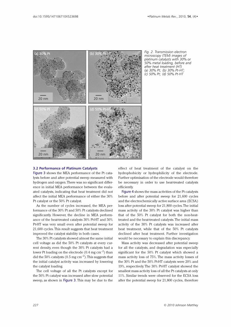
3. Results and Discussion3.1 Particle Size of Platinum CatalystsFigure 2 shows TEM images of the 30% Pt, 30% Pt-HT,
50% Pt and 50% Pt-HT catalysts. Fine particles and
good metal dispersion were obtained for the 30% Pt
and 50% Pt catalysts. The Pt dispersion of the 30%
Pt-HT and 50% Pt-HT catalysts remained good even
after heat treatment. As shown in Table I, the aver-
age particle size of the 30% Pt and 50% Pt catalysts
was estimated at 2–3 nm by TEM observation. The
average particle sizes of the heat-treated catalysts
(30% Pt-HT and 50% Pt-HT) were 3–4 nm and 4–5 nm,
respectively. It was clear that Pt particles became
larger during heat treatment at high temperature, and
this was thought to be due to agglomeration and sin-
tering (8). It was also found that smaller Pt particles
(<1 nm) disappeared after heat treatment. The cata-
lyst particle size was also checked by XRD analysis;
the average particle size of each catalyst was consis-
tent with that obtained by TEM observation.
Han et al. (8) reported the effect of heat treatment
on the growth of Pt-based catalyst particles in detail.
They found that growth of catalyst particles occurs by
agglomeration and sintering during heat treatment.
This process depends on the catalyst loading, and
catalysts with a higher metal loading are expected to
show more significant agglomeration and sintering.
This was found to be the case in the present study,
as slightly more catalyst particle growth was observed
in the 50% Pt catalyst than in the 30% Pt catalyst
after heat treatment, as shown by the XRD results
(Table I).
The increase in catalyst particle size for both the
30% Pt catalyst and the 50% Pt catalyst was less than
that observed by Han et al. (8), even though a higher
heat treatment temperature was used in the present
study. This is thought to be due to the use of a higher
surface area carbon support (800 m2 g−1 vs. 250 m2 g−1
used by Han et al. (8)), which led to a smaller num-
ber of catalyst particles per unit area.
226 © 2010 Johnson Matthey
doi:10.1595/147106710X523698 •Platinum Metals Rev., 2010, 54, (4)•
O2 /air inlet
H2 inlet
Coolant inlet
Gasket
Gas inlet
Gas outlet
Membraneelectrodeassembly
Carbon separator withsingle serpentine flowchannel; flow area = 25 cm2
Gas outlet
Coolant outlet
Fig. 1. Schematic image of the single fuel cell with a serpentine gas flow channel
3.2 Performance of Platinum CatalystsFigure 3 shows the MEA performance of the Pt cata-
lysts before and after potential sweep measured with
hydrogen and oxygen.There was no significant differ-
ence in initial MEA performance between the evalu-
ated catalysts, indicating that heat treatment did not
affect the initial MEA performance of either the 30%
Pt catalyst or the 50% Pt catalyst.
As the number of cycles increased, the MEA per-
formance of the 30% Pt and 50% Pt catalysts declined
significantly. However, the decline in MEA perform-
ance of the heat-treated catalysts 30% Pt-HT and 50%
Pt-HT was very small even after potential sweep for
21,600 cycles. This result suggests that heat treatment
improved the catalyst stability in both cases.
The 30% Pt catalysts showed almost the same initial
cell voltage as did the 50% Pt catalysts at every cur-
rent density, even though the 30% Pt catalysts had a
lower Pt loading on the electrode (0.4 mg cm−2) than
did the 50% catalysts (0.5 mg cm−2).This suggests that
the initial catalyst activity was increased by lowering
the catalyst loading.
The cell voltage of all the Pt catalysts except for
the 50% Pt catalyst was increased after slow potential
sweep, as shown in Figure 3. This may be due to the
effect of heat treatment of the catalyst on the
hydrophobicity or hydrophilicity of the electrode.
Further optimisation of the electrode would therefore
be necessary in order to use heat-treated catalysts
efficiently.
Figure 4 shows the mass activities of the Pt catalysts
before and after potential sweep for 21,600 cycles
and the electrochemically active surface area (ECSA)
loss after potential sweep for 21,800 cycles.The initial
mass activity of the 30% Pt catalyst was higher than
that of the 50% Pt catalyst for both the non-heat-
treated and the heat-treated catalysts.The initial mass
activity of the 30% Pt catalysts was increased after
heat treatment, while that of the 50% Pt catalysts
declined after heat treatment. Further investigation
would be necessary to explain this discrepancy.
Mass activity was decreased after potential sweep
for all the catalysts, and degradation was especially
significant for the 50% Pt catalyst which showed a
mass activity loss of 75%. The mass activity losses of
the 30% Pt and the 50% Pt-HT catalysts were 20% and
19%, respectively. The 30% Pt-HT catalyst showed the
smallest mass activity loss of all the Pt catalysts at only
11%. Similar trends were observed for the ECSA loss
after the potential sweep for 21,800 cycles, therefore
227 © 2010 Johnson Matthey
doi:10.1595/147106710X523698 •Platinum Metals Rev., 2010, 54, (4)•
20 nm
(a) 30% Pt
20 nm
(b) 30% Pt-HT
20 nm
(c) 50% Pt
20 nm
(d) 50% Pt-HT
Fig. 2. Transmission electronmicroscopy (TEM) images ofplatinum catalysts with 30% or50% metal loading, before andafter heat treatment (HT)(a) 30% Pt; (b) 30% Pt-HT;(c) 50% Pt; (d) 50% Pt-HT

it may be supposed that the mass activity loss was
related to the decrease in ECSA.
3.3 Stability of Platinum CatalystsIn this study, a potential sweep from 0.65 V to 1.05 V
was applied to the cathode to accelerate catalyst
degradation. The upper voltage was limited to 1.05 V
in order to prevent carbon corrosion from affecting
the total performance degradation of the MEA.
Makharia et al. (5) reported the effect of voltage on
carbon weight loss. Based on their data, it was
expected that the carbon support would not be
damaged if the upper voltage was limited to 1.05 V.
Therefore, it was assumed that the catalyst degradation
observed in the present study was dominated only by
the dissolution and redeposition of Pt, as reported by
Ferreira et al. (4). Figure 3 shows that the degradation
of cell voltage could be controlled by heat treatment
of the Pt catalysts. This is thought to be due to a higher
initial surface area which reduces the possibility of
dissolution and redeposition of Pt and hence particle
size growth. In addition, the disappearance of very
fine Pt particles (less than 1 nm) may also have a sta-
bilising effect as these very fine particles are unstable.
228 © 2010 Johnson Matthey
doi:10.1595/147106710X523698 •Platinum Metals Rev., 2010, 54, (4)•
Current density, A cm–2
(a) 30% Pt
Cell
volta
ge, V
1.1
1.0
0.9
0.8
0.7
0.6
0.50 0.5 1 1.5
Current density, A cm–2
Cell
volta
ge, V
1.1
1.0
0.9
0.8
0.7
0.6
0.50 0.5 1 1.5
Current density, A cm–2
(c) 50% Pt
Cell
volta
ge, V
1.1
1.0
0.9
0.8
0.7
0.6
0.50 0.5 1 1.5
Current density, A cm–2
Cell
volta
ge, V
1.1
1.0
0.9
0.8
0.7
0.6
0.50 0.5 1 1.5
(b) 30% Pt-HT
(d) 50% Pt-HT
Fig. 3. Membrane electrode assembly (MEA) performance of platinum catalysts with 30% or 50% metalloading, before and after heat treatment (HT): (a) 30% Pt; (b) 30% Pt-HT; (c) 50% Pt; (d) 50% Pt-HT.Current–voltage performance measured with hydrogen and oxygen at 80ºC: before pretreatment ( ),after slow potential sweep ( ), after fast potential sweep for 10,800 cycles ( ), and after fast potential sweepfor 21,600 cycles ( ). Flow rate of H2/O2 was 1000/1000 sccm, humidity condition of H2/O2 was 90ºC/dry,gas pressure of H2/O2 was ambient

A decrease in metal loading of the catalyst would
normally be expected to increase the catalyst surface
area, and hence increase the catalyst activity. On the
other hand, catalysts with a low metal loading tend to
be less stable due to their small particle size. In this
study, however, little difference was observed between
the cell voltage of the 30% Pt catalyst and that of the
50% Pt catalyst, even though the 30% Pt catalyst elec-
trode had a lower Pt loading. The 30% Pt catalyst
showed better stability than the 50% Pt catalyst. This
may be due to the effect of the distance between Pt
particles, although further theoretical investigation
would be necessary to fully understand this result.
3.4 Particle Size of Platinum-Cobalt CatalystsFigure 5 shows TEM images of the 30% PtCo-HT, 50%
PtCo-HT and 50% PtCo-HHT catalysts. The average
particle sizes of the catalysts are given in Table I. The
particle size and dispersion of the 30% PtCo-HT and
50% PtCo-HT catalysts were very similar to those of
the 30% Pt-HT and the 50% Pt-HT catalysts, respec-
tively, as both were subjected to heat treatment at the
same temperature. There were no small metal parti-
cles on the carbon support for any of these catalysts.
The particle size distributions of both the 30% and
50% PtCo-HT catalysts were uniform, but that of the
50% PtCo-HHT catalyst was not uniform and included
229 © 2010 Johnson Matthey
doi:10.1595/147106710X523698 •Platinum Metals Rev., 2010, 54, (4)•
Mas
s ac
tivity
, A g
–1Pt
200
160
120
80
40
030% Pt 30% Pt-HT 50% Pt 50% Pt-HT
ECSA
loss, %
100
80
60
40
20
0
Mass activity before potential sweepMass activity after potential sweepECSA loss after potential sweepX
X
X
X
X
Fig. 4. Mass activity ofplatinum catalysts with30% or 50% metalloading, before andafter heat treatment(HT) at 0.9 V withhydrogen and oxygenat 80ºC: beforepretreatment and afterfast potential sweep for21,600 cycles. On thesecondary axis theelectrochemical surfacearea (ECSA) loss after21,800 cycles is plotted
20 nm
(a) 30% PtCo -HT
20 nm
(b) 50% PtCo-HT
20 nm
(c) 50% PtCo-HHT
Fig. 5. Transmission electron microscopy (TEM) images of platinum-cobalt catalysts with 30% or 50% metalloading after heat treatment (HT) and after heat treatment at a higher temperature (HHT): (a) 30% PtCo-HT;(b) 50% PtCo-HT; (c) 50% PtCo-HHT

some very large particles due to the higher heat treat-
ment temperature used.
3.5 Performance of Platinum-Cobalt CatalystsFigure 6 shows MEA performances of the PtCo cata-
lysts before and after potential sweep with hydrogen
and oxygen. Although the surface area of the 30%
PtCo-HT catalyst was higher than that of the 50%
PtCo-HT catalyst, its initial cell voltage was lower. This
suggests that more pretreatment is needed for the
lower-loading catalysts.
The 30% PtCo-HT catalyst showed better perform-
ance than the 50% PtCo-HT catalyst despite its lower
Pt loading. The performance loss of the 50% PtCo-HT
catalyst after potential sweep for 21,600. The perform-
ance loss of the 50% PtCo-HT catalyst after the 21,600
cycles of fast potential sweep was the largest of all
the evaluated catalysts. As the number of cycles
increased, the MEA performance of all the heat-
treated PtCo catalysts declined, unlike the heat-
treated Pt catalysts. The high initial performance of
the PtCo catalysts was thought to be due to the effect
of Co increasing oxygen reduction reaction (ORR)
activity, therefore the loss in MEA performance
observed for the PtCo catalyst after potential sweep
may be caused by the dissolution of Co into the
ionomer during the accelerated degradation test.
However, further investigation would be required to
prove this and to fully understand the degradation
mechanism.
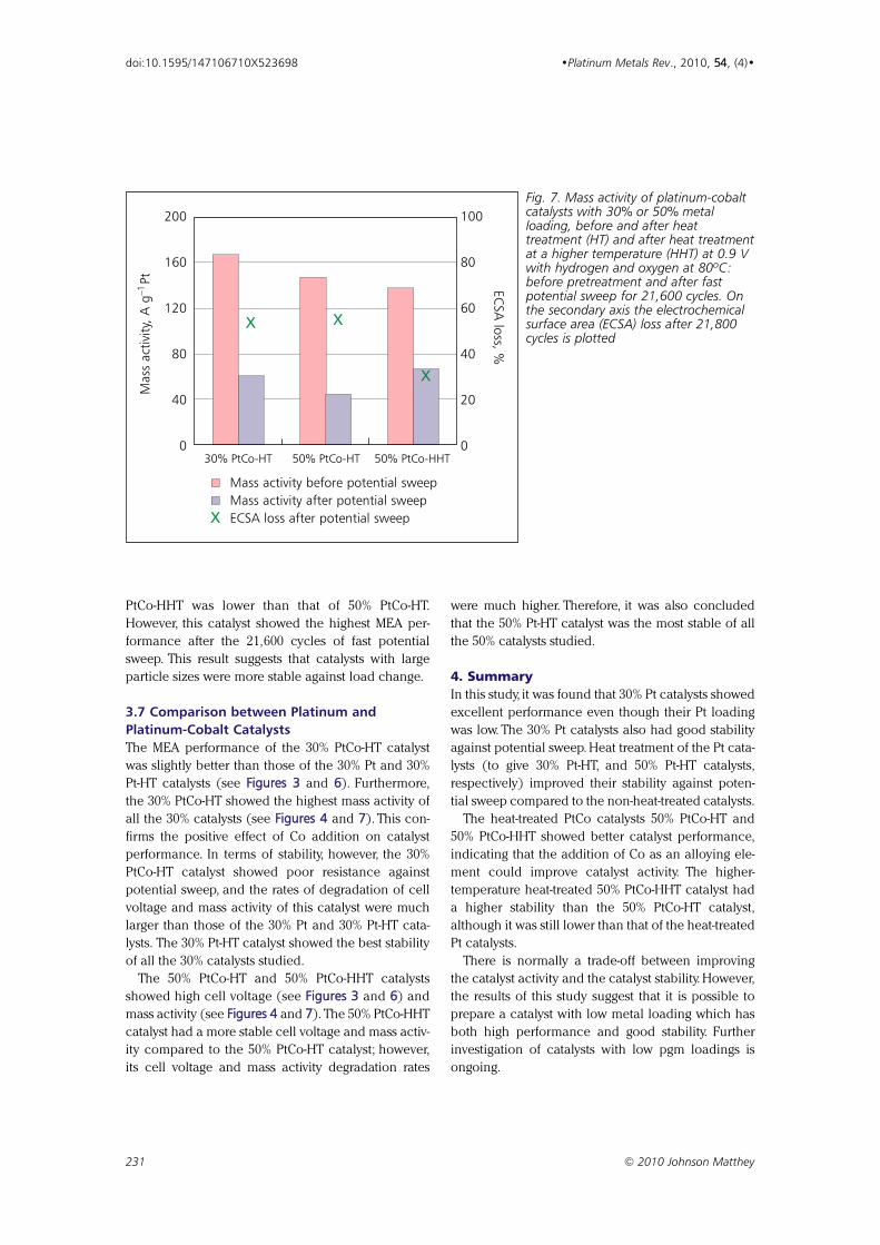
Figure 7 shows the mass activity of the PtCo cata-
lysts at 0.9 V before and after potential sweep.The ini-
tial mass activity increased with decreasing metal
loading (that is, increased metal surface area). The
50% PtCo-HHT catalyst showed high mass activity
even though it had large particles (that is, decreased
metal surface area). This may be due to the relatively
high Co content of the ‘as prepared’ 50% PtCo-HHT
catalyst (Pt:Co ratio was 1.9:1).
The 50% PtCo-HHT catalyst showed the highest
mass activity of all the evaluated PtCo catalysts after
the 21,600 cycles of fast potential sweep. During the
cycling, Pt and Co dissolved into the ionomer. Less Co
was dissolved out of the 50% PtCo-HHT catalyst,
enabling it to maintain its mass activity even after
cycling.
3.6 Stability of Platinum-Cobalt CatalystsThe degradation rate of the 50% PtCo-HT was 7% and
that of 50% PtCo-HHT was 4% at a current density of
0.5 A cm−2. The initial performance of the 50%
230 © 2010 Johnson Matthey
doi:10.1595/147106710X523698 •Platinum Metals Rev., 2010, 54, (4)•
Current density, A cm–2
(a) 30% PtCo-HT
Cell
volta
ge, V
1.1
1.0
0.9
0.8
0.7
0.6
0.50 0.5 1 1.5
Current density, A cm–2
(b) 50% PtCo-HTCe
ll vo
ltage
, V1.1
1.0
0.9
0.8
0.7
0.6
0.50 0.5 1 1.5
Current density, A cm–2
(c) 50% PtCo-HHT
Cell
volta
ge, V
1.1
1.0
0.9
0.8
0.7
0.6
0.50 0.5 1 1.5
Fig. 6. Membrane electrode assembly (MEA)performance of platinum-cobalt catalysts with 30%or 50% metal loading, before and after heattreatment (HT) and after heat treatment at a highertemperature (HHT): (a) 30% PtCo-HT; (b) 50%PtCo-HT; (c) 50% PtCo-HHT. Current–voltageperformance measured with hydrogen and oxygenat 80ºC: before pretreatment ( ), after slowpotential sweep ( ), after fast potential sweep for10,800 cycles ( ), and after fast potential sweepfor 21,600 cycles ( ). Flow rate of H2/O2 was1000/1000 sccm, humidity condition of H2/O2 was90ºC/dry, gas pressure of H2/O2 was ambient
PtCo-HHT was lower than that of 50% PtCo-HT.
However, this catalyst showed the highest MEA per-
formance after the 21,600 cycles of fast potential
sweep. This result suggests that catalysts with large
particle sizes were more stable against load change.
3.7 Comparison between Platinum andPlatinum-Cobalt CatalystsThe MEA performance of the 30% PtCo-HT catalyst
was slightly better than those of the 30% Pt and 30%
Pt-HT catalysts (see Figures 3 and 6). Furthermore,
the 30% PtCo-HT showed the highest mass activity of
all the 30% catalysts (see Figures 4 and 7). This con-
firms the positive effect of Co addition on catalyst
performance. In terms of stability, however, the 30%
PtCo-HT catalyst showed poor resistance against
potential sweep, and the rates of degradation of cell
voltage and mass activity of this catalyst were much
larger than those of the 30% Pt and 30% Pt-HT cata-
lysts. The 30% Pt-HT catalyst showed the best stability
of all the 30% catalysts studied.
The 50% PtCo-HT and 50% PtCo-HHT catalysts
showed high cell voltage (see Figures 3 and 6) and
mass activity (see Figures 4 and 7). The 50% PtCo-HHT
catalyst had a more stable cell voltage and mass activ-
ity compared to the 50% PtCo-HT catalyst; however,
its cell voltage and mass activity degradation rates
were much higher. Therefore, it was also concluded
that the 50% Pt-HT catalyst was the most stable of all
the 50% catalysts studied.
4. SummaryIn this study, it was found that 30% Pt catalysts showed
excellent performance even though their Pt loading
was low. The 30% Pt catalysts also had good stability
against potential sweep. Heat treatment of the Pt cata-
lysts (to give 30% Pt-HT, and 50% Pt-HT catalysts,
respectively) improved their stability against poten-
tial sweep compared to the non-heat-treated catalysts.
The heat-treated PtCo catalysts 50% PtCo-HT and
50% PtCo-HHT showed better catalyst performance,
indicating that the addition of Co as an alloying ele-
ment could improve catalyst activity. The higher-
temperature heat-treated 50% PtCo-HHT catalyst had
a higher stability than the 50% PtCo-HT catalyst,
although it was still lower than that of the heat-treated
Pt catalysts.
There is normally a trade-off between improving
the catalyst activity and the catalyst stability. However,
the results of this study suggest that it is possible to
prepare a catalyst with low metal loading which has
both high performance and good stability. Further
investigation of catalysts with low pgm loadings is
ongoing.
231 © 2010 Johnson Matthey
doi:10.1595/147106710X523698 •Platinum Metals Rev., 2010, 54, (4)•
Mas
s ac
tivity
, A g
–1Pt
200
160
120
80
40
030% PtCo-HT 50% PtCo-HT 50% PtCo-HHT
ECSA
loss, %
100
80
60
40
20
0
X X
X
Mass activity before potential sweepMass activity after potential sweepECSA loss after potential sweepX
Fig. 7. Mass activity of platinum-cobaltcatalysts with 30% or 50% metalloading, before and after heattreatment (HT) and after heat treatmentat a higher temperature (HHT) at 0.9 Vwith hydrogen and oxygen at 80ºC:before pretreatment and after fastpotential sweep for 21,600 cycles. Onthe secondary axis the electrochemicalsurface area (ECSA) loss after 21,800cycles is plotted

The AuthorsKoichi Matsutani is a Senior Research Engineerand leader of the fuel cell business developmentdivision at TKK. One of his major efforts is devel-oping high performance anode catalysts forDMFCs. He is now leading a research and devel-opment team and his present interest is develop-ing a new-concept platinum catalyst to reduceloadings in PEFCs.
Katsuichiro Hayakawa is a Research Engineer inthe fuel cell business development division atTKK. He has been developing durable and highperformance cathode catalysts for PEFCs. Hispresent interest is improving the stability of plat-inum and platinum-cobalt catalysts by controllingparticle size, surface structure and distribution.
Tomoyuki Tada is the Principal Engineer of thefuel cell business development division at TKK. Hedeveloped several of TKK’s current standard cata-lysts, including platinum-ruthenium, platinum-cobalt, and platinum on graphitised carbon cata-lysts. He has been newly appointed to the posi-tion of Manager of the manufacturing technologydepartment of TKK’s Isehara plant, which aims todevelop superior pgm materials and equipmentfor the glass industry.
References
1 K. Kinoshita, J. T. Lundquist and P. Stonehart,J. Electoanal. Chem., 1973, 48, (2), 157
2 T. Patterson, ‘Effect of Potential Cycling on Loss ofElectrochemical Surface Area of Platinum Catalyst inPolymer Electrolyte Membrane Fuel Cell’, in “AIChESpring National Meeting Proceedings”, 2002, p. 313
3 P. Yu, M. Pemberton and P. Plasse, J. Power Sources,2005, 144, (1), 11
4 P. J. Ferreira, G. J. la O’, Y. Shao-Horn, D. Morgan,R. Makharia, S. Kocha and H. A. Gasteiger, J. Electrochem.Soc., 2005, 152, (11), A2256
5 R. Makharia, S. Kocha, P. Yu, M. A. Sweikart, W. Gu,F. Wagner and H. A. Gasteiger, ECS Trans., 2006,1, (8), 3
6 T. Tada, N. Toshima, Y. Yamamoto and M. Inoue,Electrochemistry (Jpn.), 2007, 75, (2), 221
7 S. Chen, H. A. Gasteiger, K. Hayakawa, T. Tada andY. Shao-Horn, J. Electrochem. Soc., 2010, 157, (1),A82
8 K. S. Han, Y.-S. Moon, O. H. Han, K. J. Hwang, I. Kim andH. Kim, Electrochem. Commun., 2007, 9, (2), 317
232 © 2010 Johnson Matthey
doi:10.1595/147106710X523698 •Platinum Metals Rev., 2010, 54, (4)•