effect of particle size distribution of …gjesrm.com/issues...
TRANSCRIPT

[Mahmood et al., 3(10): October, 2016] ISSN 2349-4506 Impact Factor: 2.785
Global Journal of Engineering Science and Research Management
http: // www.gjesrm.com © Global Journal of Engineering Science and Research Management
[45]
EFFECT OF PARTICLE SIZE DISTRIBUTION OF COHESION LESS SOILS AND
PILE DIAMETERS ON THE BEHAVIOR OF SOIL COLUMN INSIDE THE OPEN
ENDED PIPE PILES UNDER DIFFERENT SATURATION CONDITIONS Mahmood R. Mahmood*, Samer J. Abdullah Qadir
* Assistant Professor, Building and Construction Engineering Department, University of Technology,
Baghdad, Iraq
Researcher, Building and Construction Engineering Department, University of Technology, Baghdad,
Iraq
DOI: 10.5281/zenodo.160702
KEYWORDS: pipe pile, soil plug, particle size distribution, pile diameter, partially saturated.
ABSTRACT This research is conducted to study the effect different grain size distribution of cohesionless soils (i.e. fine,
medium and coarse sand) and pipe pile diameters on the degree of soil plugging and plug length ratio under
different saturation conditions (i.e. fully and partially saturated).
Karbala sand, were used as a natural soil in the present study, it is poorly graded clean sand of rounded particles.
The sandy soil is sieved to obtain a fine, medium and coarse graded according to (ASTM D 422-02)[3].
The experimental model tests conducted on four open-ended steel pipe pile models with diameters of (25, 30, 35
and 41mm). embedded within different grain size distribution of sand prepared under fully and partially saturated
conditions with predetermined relative density of 65%. The unsaturated states were achieved by lowering of water
table according to predetermined matric suction values of soils. The relationship between matric suction and depth
of ground water table was measured in suction profile set by using three Tensiometers (IRROMETER). The soil,
water characteristic curve (SWCC) was estimated by applying fitting methods through the program (Soil Vision).
The results shows that, the plug length ratio (PLR) (The proportion of a soil plug length to the pile penetration
depth) which was measured for different pile diameters, and different grain size distribution in unsaturated
conditions, for the same pipe pile diameter increase with increasing the matric suction values and the length of
soil column inside the pipe pile increase gradually with the increasing of a piles diameter.
INTRODUCTION Steel pipe piles classified into two types open and closed ended pipe piles, and according to the British standard
for foundations (BS 8004, 1986)[7], the close-ended pipe piles considered large displacement piles. However the
open-ended pipe piles classified as small-displacement piles. Both of which became widely used in civil
engineering works such as submerged area and offshore structures (marine construction) because of steel pipe
piles are easy of handling, driving and its industry as compared with concrete piles, and can be driven to greater
depths. As well as their high load bearing capacity, so many times used to support heavy structures, bridge piers
construction and high buildings to ensure structural safety.
During the driving of open-ended pipe piles, the soil inside an open-ended pipe pile may form as unplugged mode
(i.e. the soil enters in the pile at the same rate of pile penetration). Partial plugging mode refers to the state where
the soil is still able to enter in the pile, but not as the same rate of the pile penetrates. On the other hand, if a pile
is driven under plugged mode (i.e. preventing new soil from entering in the pile) the internal shaft friction is large
enough to prevent the soil from entering and the pipe pile behaves similarly as a closed-ended pile. Degree of Soil
Plugging often described by the plug length ratio (PLR) (which is defined as the proportion of a soil plug length
to the pile penetration depth) (Paik et al., 2003)[17].
When the pipe pile embedded in unsaturated soils the influence of matric suction is typically not taken into account
in the conventional design. Pile foundations are usually designed based on principles of soil mechanics assuming
[Mahmood et al., 3(10): October, 2016] ISSN 2349-4506 Impact Factor: 2.785
Global Journal of Engineering Science and Research Management
http: // www.gjesrm.com © Global Journal of Engineering Science and Research Management
[46]
that the soil is in dry condition, fully saturated, or submerged. Experimental and theoretical difficulties (e.g. direct
measurement of suction, large number of influencing factors) delayed considerably the development of an
understanding of the behavior of partially saturated soils. It is only during the last few decades that theoretical
frameworks and constitutive models have been proposed to describe the mechanical behavior of such soils.
(Luking and Kempfert, 2013)[15] investigated the influence of different factors on the plugging effect and the
change in the load-bearing behavior, mainly in non-cohesive soils using experimental, numerical and statistical
methods during jacking an open-ended displacement pile. The soil is entering through the pile toe into the profile;
this plug can close up the pile toe completely. Because of such reason, the pile can be treated approximately as a
fully closed-ended displacement pile and can mobilize an additional base resistance. Indeed, the soil-mechanical
processes and the different factors of influence on the plugging effect are mostly unknown. All investigations
showed that a fully plugged soil inside the pile could not be identified and disproved the classical model
representation of a fully plugged pile toe. The load transfer in the plug takes place by compression arches, which
are mainly influenced by the pile diameter and the soil density. Finally, based on these results a practical
calculation method was suggested.
(Shijhait and Fattah, 2013)[19] investigated the effect of plugging on the load carrying capacity of close and open
ended pipe piles embedded in sandy soil. It was found that the behavior of open-ended pipe piles and close-ended
piles where similar, if when the soil plug formed inside piles in a state of partial plug or full plug. Length of the
soil plug based on the type of installation and relative density, whether open-ended piles are driven or pressed in
the fully unplugged mode or in the partially plugged mode, the plug does contribute to static pile base capacity.
When a pipe pile is driven to a depth equal to fifteen times of its inside diameter, it behaved as a solid base and
the load carrying capacity of a fully plugged open ended pipe pile was equal or greater than that of the closed-
ended pile.
(Hassan and Al-Qaissy, 2015)[10] investigated the effect of matric suction on the ultimate load carrying capacity
of the pipe piles foundation embedded within unsaturated cohesionless soils. The experimental work consisted of
20 models of pipe piles. These models included four different configuration of piles, and at different states; dry
condition, fully saturated condition and unsaturated conditions with three different matric suction values (6kPa ,
8.5kPa and 10.5kPa). The matric suction values of the soils were achieved by controlling the level of the water
table in the soil container and confirmed by using Tensiometers installed within the soil at different depths. The
soil water characteristic curve (SWCC) was estimated by applying fitting methods through the software (Soil
Vision) after identifying the basic properties of the soil. From experimental work results, it was found that the
matric suction has a clear influence on the ultimate load capacity for all models of pipe piles tested and the
variations of load carrying capacity with respect to matric suction were similar to that of shear strength of
unsaturated soils.
The main objectives of this research is to investigate the effect of pile diameters and particle size distribution of
cohesionless soils (i.e. fine, medium and coarse sand) on the degree of soil plugging behavior of single pipe piles
under fully and partially saturated conditions with different matric suction values according to the sandy soil bed.
SOILS AND MATERIALS USED The Soils Used
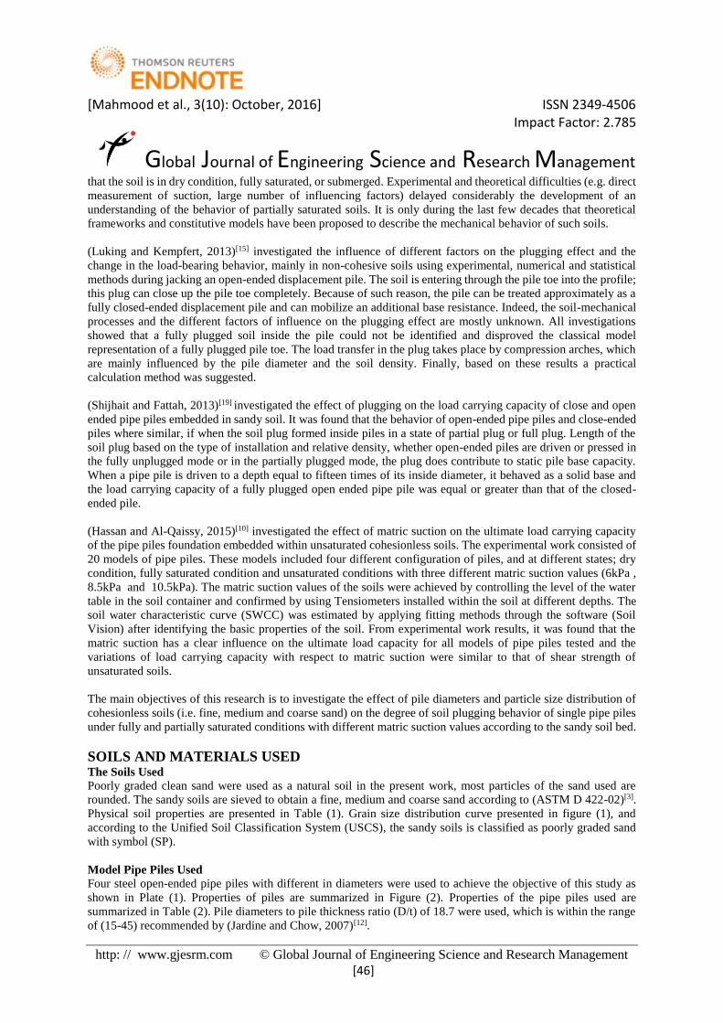
Poorly graded clean sand were used as a natural soil in the present work, most particles of the sand used are
rounded. The sandy soils are sieved to obtain a fine, medium and coarse sand according to (ASTM D 422-02)[3].
Physical soil properties are presented in Table (1). Grain size distribution curve presented in figure (1), and
according to the Unified Soil Classification System (USCS), the sandy soils is classified as poorly graded sand
with symbol (SP).
Model Pipe Piles Used
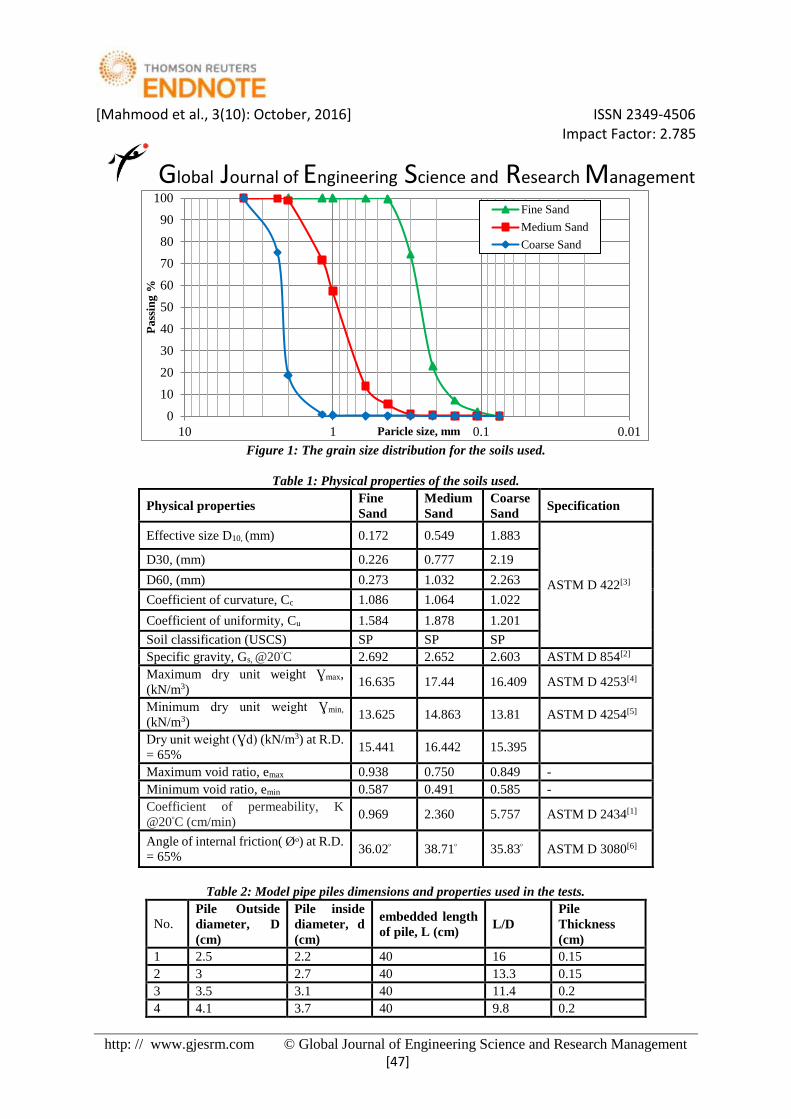
Four steel open-ended pipe piles with different in diameters were used to achieve the objective of this study as
shown in Plate (1). Properties of piles are summarized in Figure (2). Properties of the pipe piles used are
summarized in Table (2). Pile diameters to pile thickness ratio (D/t) of 18.7 were used, which is within the range
of (15-45) recommended by (Jardine and Chow, 2007)[12].
[Mahmood et al., 3(10): October, 2016] ISSN 2349-4506 Impact Factor: 2.785
Global Journal of Engineering Science and Research Management
http: // www.gjesrm.com © Global Journal of Engineering Science and Research Management
[47]
Figure 1: The grain size distribution for the soils used.
Table 1: Physical properties of the soils used.
Physical properties Fine
Sand
Medium
Sand
Coarse
Sand Specification
Effective size D10, (mm) 0.172 0.549 1.883
ASTM D 422[3]
D30, (mm) 0.226 0.777 2.19
D60, (mm) 0.273 1.032 2.263
Coefficient of curvature, Cc 1.086 1.064 1.022
Coefficient of uniformity, Cu 1.584 1.878 1.201
Soil classification (USCS) SP SP SP
Specific gravity, Gs, @20ᵒC 2.692 2.652 2.603 ASTM D 854[2]
Maximum dry unit weight Ɣmax,
(kN/m3) 16.635 17.44 16.409 ASTM D 4253[4]
Minimum dry unit weight Ɣmin,
(kN/m3) 13.625 14.863 13.81 ASTM D 4254[5]
Dry unit weight (Ɣd) (kN/m3) at R.D.
= 65% 15.441 16.442 15.395
Maximum void ratio, emax 0.938 0.750 0.849 -
Minimum void ratio, emin 0.587 0.491 0.585 -
Coefficient of permeability, K
@20ᵒC (cm/min) 0.969 2.360 5.757 ASTM D 2434[1]
Angle of internal friction( Øᵒ) at R.D.
= 65% 36.02ᵒ 38.71ᵒ 35.83ᵒ ASTM D 3080[6]
Table 2: Model pipe piles dimensions and properties used in the tests.
No. Pile Outside
diameter, D
(cm)
Pile inside
diameter, d
(cm)
embedded length
of pile, L (cm) L/D
Pile
Thickness
(cm)
1 2.5 2.2 40 16 0.15
2 3 2.7 40 13.3 0.15
3 3.5 3.1 40 11.4 0.2
4 4.1 3.7 40 9.8 0.2
0
10
20
30
40
50
60
70
80
90
100
0.010.1110
Pass
ing
%
Paricle size, mm
Fine Sand
Medium Sand
Coarse Sand
[Mahmood et al., 3(10): October, 2016] ISSN 2349-4506 Impact Factor: 2.785
Global Journal of Engineering Science and Research Management
http: // www.gjesrm.com © Global Journal of Engineering Science and Research Management
[48]
Plate 1: Pipe piles models.
Model Setup Formulation
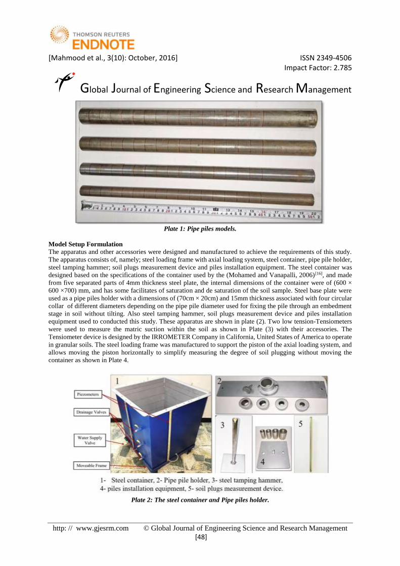
The apparatus and other accessories were designed and manufactured to achieve the requirements of this study.
The apparatus consists of, namely; steel loading frame with axial loading system, steel container, pipe pile holder,
steel tamping hammer; soil plugs measurement device and piles installation equipment. The steel container was
designed based on the specifications of the container used by the (Mohamed and Vanapalli, 2006)[16], and made
from five separated parts of 4mm thickness steel plate, the internal dimensions of the container were of (600 ×
600 ×700) mm, and has some facilitates of saturation and de saturation of the soil sample. Steel base plate were
used as a pipe piles holder with a dimensions of (70cm × 20cm) and 15mm thickness associated with four circular
collar of different diameters depending on the pipe pile diameter used for fixing the pile through an embedment
stage in soil without tilting. Also steel tamping hammer, soil plugs measurement device and piles installation
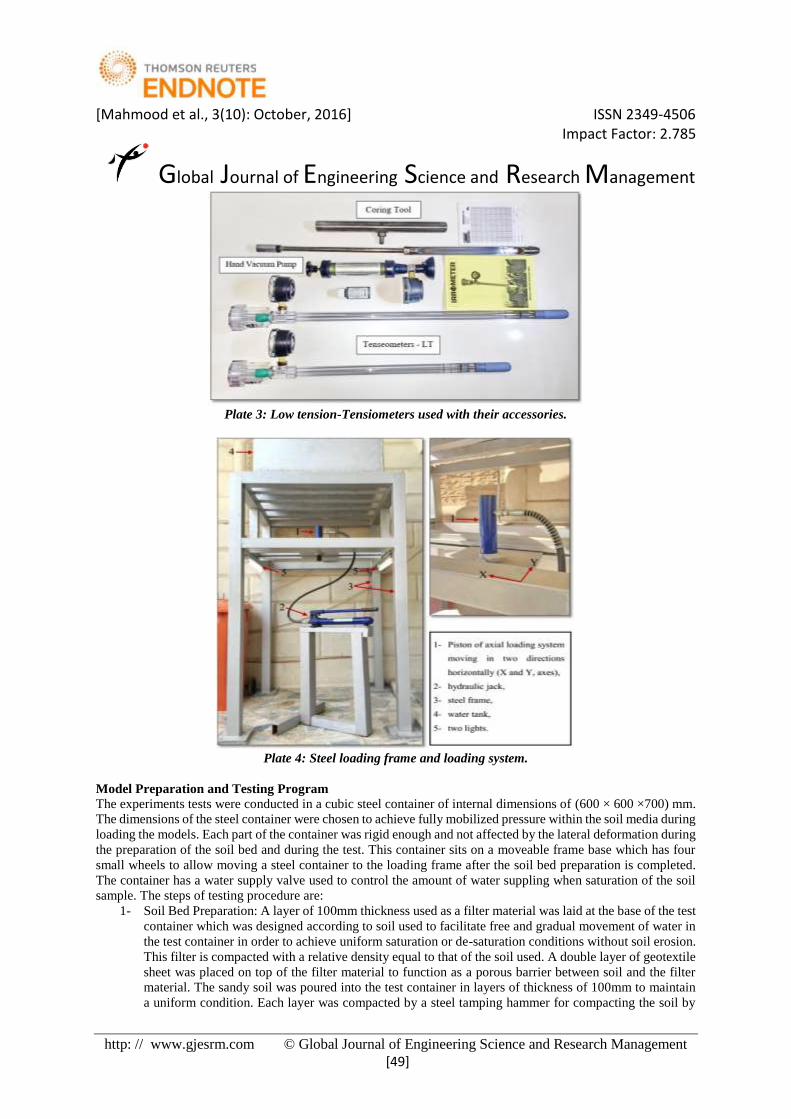
equipment used to conducted this study. These apparatus are shown in plate (2). Two low tension-Tensiometers
were used to measure the matric suction within the soil as shown in Plate (3) with their accessories. The
Tensiometer device is designed by the IRROMETER Company in California, United States of America to operate
in granular soils. The steel loading frame was manufactured to support the piston of the axial loading system, and
allows moving the piston horizontally to simplify measuring the degree of soil plugging without moving the
container as shown in Plate 4.
Plate 2: The steel container and Pipe piles holder.
[Mahmood et al., 3(10): October, 2016] ISSN 2349-4506 Impact Factor: 2.785
Global Journal of Engineering Science and Research Management
http: // www.gjesrm.com © Global Journal of Engineering Science and Research Management
[49]
Plate 3: Low tension-Tensiometers used with their accessories.
Plate 4: Steel loading frame and loading system.
Model Preparation and Testing Program
The experiments tests were conducted in a cubic steel container of internal dimensions of (600 × 600 ×700) mm.
The dimensions of the steel container were chosen to achieve fully mobilized pressure within the soil media during
loading the models. Each part of the container was rigid enough and not affected by the lateral deformation during
the preparation of the soil bed and during the test. This container sits on a moveable frame base which has four
small wheels to allow moving a steel container to the loading frame after the soil bed preparation is completed.
The container has a water supply valve used to control the amount of water suppling when saturation of the soil
sample. The steps of testing procedure are:
1- Soil Bed Preparation: A layer of 100mm thickness used as a filter material was laid at the base of the test
container which was designed according to soil used to facilitate free and gradual movement of water in
the test container in order to achieve uniform saturation or de-saturation conditions without soil erosion.
This filter is compacted with a relative density equal to that of the soil used. A double layer of geotextile
sheet was placed on top of the filter material to function as a porous barrier between soil and the filter
material. The sandy soil was poured into the test container in layers of thickness of 100mm to maintain
a uniform condition. Each layer was compacted by a steel tamping hammer for compacting the soil by
[Mahmood et al., 3(10): October, 2016] ISSN 2349-4506 Impact Factor: 2.785
Global Journal of Engineering Science and Research Management
http: // www.gjesrm.com © Global Journal of Engineering Science and Research Management
[50]
uniformly distributed blows to maintain the uniform density of the desired relative density of 65%, the
surface of the soil is scraped and leveled by a sharp edge ruler to get as near as possible a flat surface.
2- Saturation of soil model: Water supplier was connected to the lower valve of soil container using a thin
plastic tube. This valve fixed at the base of the soil container to provide access of water to the prepared
sand in the container under a controlled head of water. Water flows through a filter soil layer in container
base and rises up from bottom slowly until the sand is fully saturated (i.e. the water table reaches the
sand surface in the container). The water level monitored by piezometers, which were fixed at the four
sides of the container. The supplier valve was closed once the water level reached the soil surface in the
tank. This technique facilitated escape of air from bottom to the surface layers of the sand in the container
gradually to ensure a fully saturated condition. Plate 5 shows the saturation of soil model.
3- Partially saturated soil setup: After saturation the dry soil bed and for partially saturation test, the water
table was lowered by using four drainage valves fixed vertically along one side of the container to a
different levels below the soil surface (i.e., 150 mm, 300 mm and 450 mm) to achieve different suction
values. Piezometers were used to monitor the level of the water table in the container, which were fixed
at the four sides of the container. Equilibrium conditions with respect to suction value in the soil were
typically achieved at a period of 24 hours.
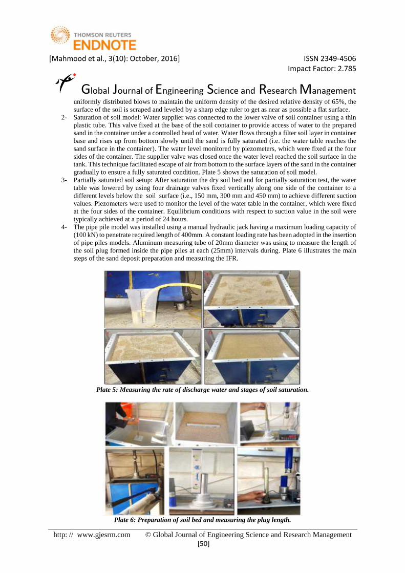
4- The pipe pile model was installed using a manual hydraulic jack having a maximum loading capacity of
(100 kN) to penetrate required length of 400mm. A constant loading rate has been adopted in the insertion
of pipe piles models. Aluminum measuring tube of 20mm diameter was using to measure the length of
the soil plug formed inside the pipe piles at each (25mm) intervals during. Plate 6 illustrates the main
steps of the sand deposit preparation and measuring the IFR.
Plate 5: Measuring the rate of discharge water and stages of soil saturation.
Plate 6: Preparation of soil bed and measuring the plug length.

[Mahmood et al., 3(10): October, 2016] ISSN 2349-4506 Impact Factor: 2.785
Global Journal of Engineering Science and Research Management
http: // www.gjesrm.com © Global Journal of Engineering Science and Research Management
[51]
Suction Profile Technique
To determine suction profile the technique assumed by (Li, 2008)[13] was adopted to measure the relationship
between the matric suction and depth of ground water table depending on the container used by the researchers
(Mohamed and Vanapalli, 2006)[16], which has all facilitates to achieve the saturation and desaturation conditions
of the soil bed.
The technique of direct measurement for soil suction was done by a Tensiometer-Model LT (Low Tension) which
was imported especially for this work. The Tensiometer- low tension is able to measure the soil suction of
cohesionless soils with a range of (0-40) kilopascals. The hand vacuum pump supplied with the LT -
IRROMETER will apply a vacuum pressure for this model between (30-35 kPa) to release the air entrapped in
the ceramic disc (IRROMETER Manual Book)[11].
In this study, two Tensiometers were prepared and installed at different depths below the sandy soil surface to
measure the matric suction in a time period of 24 hours to achieve equilibrium conditions. The water contents
were determined approximately at the same levels in which the soil suction was measured. The values of water
content and matric suction used to determine the level of water table to achieve a pre-decided matric suction
profile prior to conducting pile load tests.
The water table was lowered in three stages to different levels below the soil surface (i.e., 150 mm, 300 mm and
450 mm) to achieve different suction values.
In the first stage one Tensiometer was installed at a depth of (75mm). In the second stage two Tensiometers were
installed at a depths of (75mm) and (225mm) from the soil surface respectively. In the third stage two
Tensiometers were installed at a depths of (75mm) and (225mm) from the soil surface respectively, another model
of soil bed was prepared in this stage then inserted one Tensiometer at a depths of (375mm) from the soil surface.
The stages of installing the Tensiometers shown in Plate 7. The water content and Tensiometer reading for all
stages were recorded after 24 hours as mentioned above.
Plate 7: The stages of installing the Tensiometers and applying vacuum.
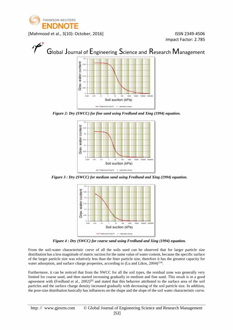
RESULTS AND DISCUSSION Soil Water Characteristic Curves Estimation of Partially Saturated Soils
The method used in this study to estimate the soil-water characteristic curve (SWCC) summarized by using the
direct method (Tensiometers) to measure the matric suction values corresponding to the moisture content
measured for all types of the soils used at different stages. Then the average matric suction and water content
values are obtained from the suction profile method and with the aid of soil basic information such as specific
gravity, dry density, water content, grain size distribution curve, and the pore size distribution which are needed
to plotted in SOILVISION database V.4 program to apply the fitting on the soil water characteristic curve (User’s
Guide Manual of SOILVISION program V.4, 2005)[21].
A mathematical model proposed by Fredlund and Xing (1994) was used to describe the soil-water characteristic
curve for all the different types of the soils used. These models were introduced to SOILVISION V.4 program
databases. Figures 2 to 4 illustrated the SWCC for soil used.
[Mahmood et al., 3(10): October, 2016] ISSN 2349-4506 Impact Factor: 2.785
Global Journal of Engineering Science and Research Management
http: // www.gjesrm.com © Global Journal of Engineering Science and Research Management
[52]
Figure 2: Dry (SWCC) for fine sand using Fredlund and Xing (1994) equation.
Figure 3 : Dry (SWCC) for medium sand using Fredlund and Xing (1994) equation.
Figure 4 : Dry (SWCC) for coarse sand using Fredlund and Xing (1994) equation.
From the soil-water characteristic curve of all the soils used can be observed that for larger particle size
distribution has a less magnitude of matric suction for the same value of water content, because the specific surface
of the larger particle size was relatively less than the finer particle size, therefore it has the greatest capacity for
water adsorption, and surface charge properties, according to (Lu and Likos, 2004)[14].
Furthermore, it can be noticed that from the SWCC for all the soil types, the residual zone was generally very
limited for coarse sand, and then started increasing gradually in medium and fine sand. This result is in a good
agreement with (Fredlund et al., 2002)[8] and stated that this behavior attributed to the surface area of the soil
particles and the surface charge density increased gradually with decreasing of the soil particle size. In addition,
the pore-size distribution basically has influences on the shape and the slope of the soil water characteristic curve.

[Mahmood et al., 3(10): October, 2016] ISSN 2349-4506 Impact Factor: 2.785
Global Journal of Engineering Science and Research Management
http: // www.gjesrm.com © Global Journal of Engineering Science and Research Management
[53]
It can be noticed also that the air-entry values increased steadily with decreasing the median grain size (D50) as
shown in Figure 5.
Figure 5: Air-entry values variation with median grain Size (D50) according to the fitting curves proposed by
(Fredlund and Xing, 1994).
Effect of Pile Diameter and Soil Particle Size on the PLR and IFR under Different Saturation Conditions
The length of soil column inside the open ended pile (plug length) measured in the end of piles installation for all
studied cases. Plug length ratio (PLR) is one of the widely indicators employed to refer to the soil plugging and
represents the ratio between soil plug length to the pile penetration depth. In this study, PLR is calculated using
following equation.
𝑃𝐿𝑅 =𝐿𝑝
𝐷ℎ
… … … (2.2)
where: LP : Length of soil plug and Dh : Pile penetration depth.
Figures 6 and 7 show the effect of grain size distribution at fully and partially saturated conditions on the plug
length ratio with different pile diameters.
Figure 6: Effect of grain size distribution for fully saturated and partially saturated (lowering 1) conditions
on the plug length ratio with different pile diameters.
0
0.5
1
1.5
2
2.5
0 0.5 1 1.5 2 2.5
Air
-en
try
va
lue
(kP
a)
Median grain size, D50 (mm)
0.1
0.2
0.3
0.4
0.5
0.6
0.7
0.8
0.9
1
2 2.5 3 3.5 4 4.5
Plu
g L
eng
th R
ati
o (
PL
R)
Piles Diameter (cm)
Fine Sand
Medium Sand
Coarse Sand
Fully Saturated State
0.1
0.2
0.3
0.4
0.5
0.6
0.7
0.8
2 2.5 3 3.5 4 4.5
Plu
g L
eng
th R
ati
o (
PL
R)
Piles Diameter (cm)
Fine Sand
Medium Sand
Coarse Sand
Partially SaturatedState (Lowering 1)

[Mahmood et al., 3(10): October, 2016] ISSN 2349-4506 Impact Factor: 2.785
Global Journal of Engineering Science and Research Management
http: // www.gjesrm.com © Global Journal of Engineering Science and Research Management
[54]
Figure 7: Effect of grain size distribution for partially saturated conditions (lowering 2and 3) on the plug length
ratio with different pile diameters.
Figures 6 and 7 show that, the plug length ratio (PLR) increased gradually with the increasing of pile diameters,
this is attributed to the load-bearing capacity on the soil column base was increased with increasing the pile
diameter and become higher than the friction forces between the soil and the inner walls of the pile. These results
were also observed by (Yu and Yang, 2012)[22] field studies.
In a fully saturated condition, the friction force between soil and pile material decline due to the decrease of skin
resistance parameters to presence of water, which leads to lubricate soil particles. In partially saturated states the
plug length ratio increased with increasing the lowering of water table with trend of increasing from coarse,
medium, fine to natural sand for all the lowering stages. This attributed to many factors effect on the length of soil
column inside the pipe pile. The first factor is the shear strength increased gradually with the measured matric
suction increases, as stated by (Toker, 2007)[20]. Therefore the load-bearing capacity of the ground will increase
with the rise of matric suction value which leads to the increase of the plug length ratio. The second factor was
during insertion open-ended pile will cause concave soil configuration at the pile toe level according to
(Paikowsky et al., 1989)[18]. In this case the arching convex consists of the soil that enter to the pipe pile which
occurs as a reaction to form a concavity in the soil due to the amount of soil compression decreased and increased
the dilation of soil when the matric suction increased as stated by (Hamid and Miller, 2009)[9] who proved that, in
unsaturated soils, the amount of compression decreased and dilation increased in sandy soils when the matric
suction increased.
The length of the soil column inside the open ended pile (plug length) measured for each (25mm) during
installation of pipe pile models. Figure (8) presents the change of soil plug length with pile penetration depth
during installation at different grain size distribution of soils and saturation conditions for pipe pile of 3.0cm
diameter.
From Figure 8 can be noted that, in fine sand the plug formed at higher penetration depth for partially saturated
states than that of fully saturated state and other grain size distribution. In medium sand the plug formed at normal
penetration depth for partially and fully saturated states with respect to other grain size distribution. Also the figure
shows that, in a fully and partially saturated states the penetration depth for access to the fully or partially plugged
mode increased with decreasing the median grain size of soil, this is due to the effect of matric suction and load-
bearing capacity of the ground in an unsaturated state, that will be increased with the rise of matric suction value,
in addition to the influencing of lubrication of soil particles with water in the fully saturated state. Furthermore it
was found that, the length of soil column increased gradually with increasing of a piles diameter, and the piles
with a smaller inside diameter exhibited more tendencies to plug than larger diameter.

[Mahmood et al., 3(10): October, 2016] ISSN 2349-4506 Impact Factor: 2.785
Global Journal of Engineering Science and Research Management
http: // www.gjesrm.com © Global Journal of Engineering Science and Research Management
[55]
Figure 8: Variation of Soil Plug Length with pile penetration depth at different grain size distribution of soils
and saturation conditions for pipe pile of 3.0cm diameter.
CONCLUSIONS
From the experimental work results and data analysis the following conclusions can be drawn:
1. From measuring the Plug Length Ratio (PLR), it is found that in unsaturated conditions, for the same
pipe pile diameter the soil plug length ratio increased with increasing each of the matric suction values
and the lowering of the water table level.
2. The plug length was measured at different pipe pile diameters, it is found that, the length of soil column
inside the pipe pile increased gradually with the increasing of a piles diameter, and the pipe piles with a
smaller inside diameter exhibited more tendencies to plug than larger diameter.
0
5
10
15
20
25
30
35
40
0 5 10 15 20 25 30 35 40
Pen
etra
tio
n D
epth
(cm
)
Soil Plug Length (cm)
Fine Sa nd
Fully Saturated State
Partially Saturated State (Lowering 1)
Partially Saturated State (Lowering 2)
Partially Saturated State (Lowering 3)
0
5
10
15
20
25
30
35
40
0 5 10 15 20 25 30 35 40
Pen
etra
tio
n D
epth
(cm
)
Soil Plug Length (cm)
M edium Sa nd
Fully Saturated State
Partially Saturated State (Lowering 1)
Partially Saturated State (Lowering 2)
Partially Saturated State (Lowering 3)
0
5
10
15
20
25
30
35
40
0 5 10 15 20 25 30 35 40
Pen
etra
tio
n D
epth
(cm
)
Soil Plug Length (cm)
Co a rse Sa nd
Fully Saturated State
Partially Saturated State (Lowering 1)
Partially Saturated State (Lowering 2)
Partially Saturated State (Lowering 3)
[Mahmood et al., 3(10): October, 2016] ISSN 2349-4506 Impact Factor: 2.785
Global Journal of Engineering Science and Research Management
http: // www.gjesrm.com © Global Journal of Engineering Science and Research Management
[56]
3. In fine sand the plug formed at higher penetration depth for partially saturated states than that of fully
saturated state and other grain size distribution. In medium sand the plug formed at normal penetration
depth for partially and fully saturated states with respect to other grain size distribution.
4. In a fully and partially saturated condition for the same pile diameter the penetration depth for access to
the fully or partially plugged mode increased with decreasing the median grain size of soils (D50).
5. From Soil water characteristic curves (SWCC) and the results of the suction profile set, it is found that
the larger particle size has a less magnitude of matric suction at the same value of water content, and the
air-entry values increased with decreasing the median particle size (D50). On the other hand, the residual
zone in soil-water characteristic curve increased with increasing the median particle size (D50).
REFERENCES [1] American Society of Testing and Materials (ASTM) (2006). " Permeability of Granular Soils (Constant
Head)" ASTM D2434-06, West Conshohocken, Pennsylvania, USA.
[2] American Society of Testing and Materials (ASTM) (2006). "Standard test method for specific gravity of
soil solids by water pycnometer" ASTM D854, West Conshohocken, Pennsylvania, USA.
[3] American Society of Testing and Materials (ASTM) (2006). "Standard Test Method for Particle
SizeAnalysis of Soils" ASTM D422-02 (2002), West Conshohocken, Pennsylvania, USA.
[4] American Society of Testing and Materials (ASTM) (2006). "Standard Test Method for Maximum Index
Density and Unit Weight of Soils Using a Vibratory Table" ASTM D4253-00 (2006), West Conshohocken,
Pennsylvania, USA.
[5] American Society of Testing and Materials (ASTM) (2006). "Standard Test Method for Minimum Index
Density and Unit Weight of Soils and Calculation of Relative Density" ASTM D4254-00 (2006), West
Conshohocken, Pennsylvania, USA.
[6] American Society of Testing and Materials (ASTM) (2006). "Standard Test Method for Direct Shear Test
of Soils Under Consolidated Drained Conditions" ASTM D3080, West Conshohocken, Pennsylvania,
USA.
[7] BSI 8004 (1986), "Code of Practice for Foundations", London: British Standards Institution.
[8] Fredlund, M. D., Wilson, G. W., and Fredlund, D. G. (2002), "Use of the Grain Size Distribution for
Estimation of the Soil-Water Characteristic Curve", Canadian Geotechnical Journal, Vol. 39, No. 5, pp.
1103-1117.
[9] Hamid, T. B., and Miller, G. A. (2009), "Shear Strength of Unsaturated Soil Interfaces", Canadian
Geotechnical Journal, Vol. 46, No. 5, pp. 595-606.
[10] Hassan, A. M. and Al-Qaissy, M. R. (2015), “Experimental Study on Pipe Pile Models Embedded in
Partially Saturated Sand”, M.Sc. Thesis, Department of Civil Engineering, University of Technology,
Baghdad, Iraq.
[11] Irrometer Manual Book, Irrometer Company Inc., Riverside, California,
USA.
[12] Jardine, R. J., and Chow, F. C. (2007). "Some Recent Developments in Offshore Pile Design". OFFSHORE
SITE INVESTIGATION AND GEOTECHNICS, Confronting New Challenges and Sharing Knowledge,
pp. 303-332.
[13] Li, X. (2008), "Laboratory Studies on the Bearing Capacity of Unsaturated Sands", MSc. Thesis,
University of Ottawa.
[14] Lu, N., and Likos, W. J. (2004), "Unsaturated Soil Mechanics": John Wiley & Sons, New York.
[15] Luking, J., and Kempfert, H. (2013), "Plugging Effect of Open-Ended Displacement Piles", Proceedings
of the 18th International Conference on Soil Mechanics and Geotechnical Engineering, Paris, pp. 2363-
2366.
[16] Mohamed, F., and Vanapalli, S. (2006), "Laboratory Investigations for the Measurement of the Bearing
Capacity of an Unsaturated Coarse-Grained Soil". Proceedings of the 59th Canadian Geotechnical
Conference, Vancouver, BC, pp. 1-8.
[17] Paik, K., Salgado, R., Lee, J., and Kim, B. (2003), "Behavior of Open-And Closed-Ended Piles Driven
into Sands", Journal of Geotechnical and Geoenvironmental Engineering, Vol. 129, No. 4, pp. 296-306.
[18] Paikowsky, S. G., Whitman, R. V., and Baligh, M. M. (1989), "A New Look at the Phenomenon of
Offshore Pile Plugging", Marine Georesources & Geotechnology, Vol. 8, No. 3, pp. 213-230.
[Mahmood et al., 3(10): October, 2016] ISSN 2349-4506 Impact Factor: 2.785
Global Journal of Engineering Science and Research Management
http: // www.gjesrm.com © Global Journal of Engineering Science and Research Management
[57]
[19] Shijhait, W. H. & Fattah, M. Y. (2013), "Effect of Plugging on the Load Carrying Capacity of Closed and
Open Ended Pipe Piles", M.Sc. Thesis, Civil Engineering Department, the university of Baghdad,
Baghdad, Iraq.
[20] Toker, N. K. (2007), "Modeling the Relation Between Suction, Effective Stress and Shear Strength in
Partially Saturated Granular Media", Ph. D thesis, Massachusetts Institute of Technology, Department of
Civil and Environmental Engineering.
[21] User’s Guide Manual of Soil Vision program V.4, (2005), Soil Vision Systems Ltd. Saskatoon,
Saskatchewan, Canada.
[22] Yu, F., and Yang, J. (2012), "Base Capacity of Open-Ended Steel Pipe Piles in Sand", Journal of
Geotechnical and Geoenvironmental Engineering, ASCE, Vol. 138, No. 9, pp. 1116-1128.