effect of micro textures on the cutting performance of
TRANSCRIPT

Effect of Micro Textures on the Cutting Performanceof Circular Saw Blade Under Fluid LubricationYang Lu ( [email protected] )
Shandong UniversityJIanxin Deng
Shandong UniversityQinghao sun
Shandong UniversityDongliang Ge
Shandong UniversityJiaxing Wu
Shandong UniversityZhihui Zhang
Shandong University
Research Article
Keywords: micro textures, circular saw blade, cutting performance, cutting �uids
Posted Date: February 12th, 2021
DOI: https://doi.org/10.21203/rs.3.rs-201377/v1
License: This work is licensed under a Creative Commons Attribution 4.0 International License. Read Full License

Effect of micro textures on the cutting performance of circular saw blade
under fluid lubrication
Yang Lu, Jianxin Deng *, Qinghao Sun, Dongliang Ge, Jiaxing Wu, Zhihui Zhang
Key Laboratory of High Efficiency and Clean Mechanical Manufacture of MOE, School of Mechanical
Engineering, Shandong University, Jinan 250061, China
∗ Corresponding author.
Tel.: +86 531 88399769.
E-mail address: [email protected] (Jianxin Deng).

Abstract:
In this paper, linear micro textures that parallel to the sawtooth edge were fabricated on the surface of
the high speed steel W6Mo5Cr4V2 circular saw blade by laser engraving. Further, cutting performance of
micro textured circular saw blade (TCS) and traditional circular saw blade (CS), including sawing arc
length, sawing force, sawing temperature, machined surface roughness and wear mechanism, were
investigated in sawing 304 stainless steel pipes under the cutting fluid condition. Results showed that the
largest sawing arc length and sawing force were occurred on the circular saw blade sawing outward from
the inner wall. In addition, TCS circular saw blade exhibited better cutting performance and the
mechanisms were found, on the one hand, the effective sawtooth-chip contact length was reduced due to
the micro textures fabricated on the sawtooth surface, on the other hand, cutting fluid can be better
penetrated into the micro textures and formed stable lubrication film in sawtooth-chip contact interface.
Keywords: micro textures; circular saw blade; cutting performance; cutting fluids

1. Introduction
In the manufacturing industry, sawing as the starting point of workpiece machining had become one of
the important process in the manufacturing. Cutting tools employed in the sawing process was specially,
which was characterized by a certain arrangement of the sawtooth fabricated on the cutting edge of the
tools. It can be classified into three kinds according to the application and structure of saw blade, which
were hack saw blade [1], band saw blade [2, 3], and circular saw blade [4, 5]. The circular saw blade was
widely used in the cutting of various kinds of metal and wood due to the higher machining accuracy and
cutting efficiency in comparison with the band saw blade sand hack saw blade. According to the material
and parameters of the sawtooth, the circular saw blade can be divided into two categories, one was that the
solid saw composed of high speed steel or cemented carbide; the other was that the sawtooth with good
hardness and wear resistance inserted or welded into the circular saw blade[6]. The cutting performance,
wear characteristic and dynamic stability of the circular saw blade were investigated by numerous scholars
[7–11]. Bradbury et al. [7] employed M2 high speed steel as circular saw blade material sawing
difficult-to-cut material, and indicated that the sawing characteristic of the workpiece and tools material
play a significant role in the sawing process. Alam et al. [10] presented a method to improve the stability of
the circular saw blade by controlling workpiece feed speed, and monitored the lateral deflection of the saw
blade. It indicated that the lateral deflection of circular saw blade within a desired limit.
Recently, many scholars had proved that micro textures were an effectively method to improve the
friction condition of the friction pair surface, and micro textures were widely used in piston rings, tools,
seals, wet clutches, and bearings surface [12–18]. Different types of micro textures engraved on the
surfaces of the cutting tools have shown the effect in lowering sliding friction, reducing tool-chip contact
length, promoting heat dissipation and relieving adhesive wear [19–23]. Kawasegi et al. [23] fabricated
three types of patterns (parallel, perpendicular and cross patterns) on the rake face of the cutting tools. It
was found that the textures perpendicular to the chip flow was beneficial to reduce cutting force. Deng et al.
[24] produced three rake-face textured tools with different micro structures and found that the elliptical
grooves promoted better dry cutting performance than the parallel or linear grooves. In addition, micro
textures also used in drilling and milling process[25–28]. Zhou et al. [27] successfully fabricated micro
textures parallel to the cutting edge on the rake face of the milling tools and carry out milling tests with
nano-fluids, it obtained that the cutting force, surface roughness and wear rate of the tools were
significantly decreased. Ling et al. [28] fabricated rectangular micro textures on the surface of drill tools,
and found that the micro textures effectively reduced the adhesion of the workpiece material and improved
the tools life. However, very limited research works have been reported concerning micro textures
fabricated on the sawtooth surface of the circular saw blade. Thus, the effect of micro textures on the
cutting performance of circular saw blade needed to be further studied.
In this paper, four linear micro textures that parallel to the sawtooth edge were fabricated on the
surface of the high speed steel W6Mo5Cr4V2 circular saw blade by laser engraving. Then, the depth, width
and microstructure of the micro textures were obtained. Sawing 304 stainless steel pipes tests were carried
out with the micro textured circular saw blade (TCS) under the cutting fluid condition. The sawing
properties, including sawing arc length, sawing forces, sawing temperatures, machined surface roughness
and wear of the tools were investigated. This research can provide a good reference for reducing the wear
of circular saw blade, improving the machining surface quality and prolonging the tools life. If possible,
micro textured circular saw blade will be widely applied industrially in the future.
2. Experimental details
2.1. Specimen preparation
In this paper, High speed steel W6Mo5Cr4V2 was chosen as circular saw blade material from
Yongkang Meili Juye Co., Ltd., China, the composition and mechanical properties of circular saw blade
were shown in Table 1, As shown in Fig. 1, the diameter of circular saw blade was 200 mm, thickness was
2 mm, teeth were 150, teeth space was 4.2 mm, and the installation hole diameter was 32 mm. Before
micro texturing, in order to removed surface dirt, the circular saw blade was put in the alcohol solution
ultrasonic cleaning for 15 min, and then drying for 10 min. The micro textures were designed and
fabricated on the rake face by Nd: YAG laser equipment (DP-H50, Jinan Xinchu Co., Ltd.,China) and the
processing parameters were listed in Table 2. The circular saw blade was fixed on the indexing plate,
rotated the indexing by 2.4° degrees after each machining until all the teeth were micro textured. The micro
textures of the teeth surface were observed using white light interferometer (Wyko NT9300, Veeco Inc.,
USA) and scanning electron microscope (SEM; QUANTA FEG 250, FEI Inc., USA).
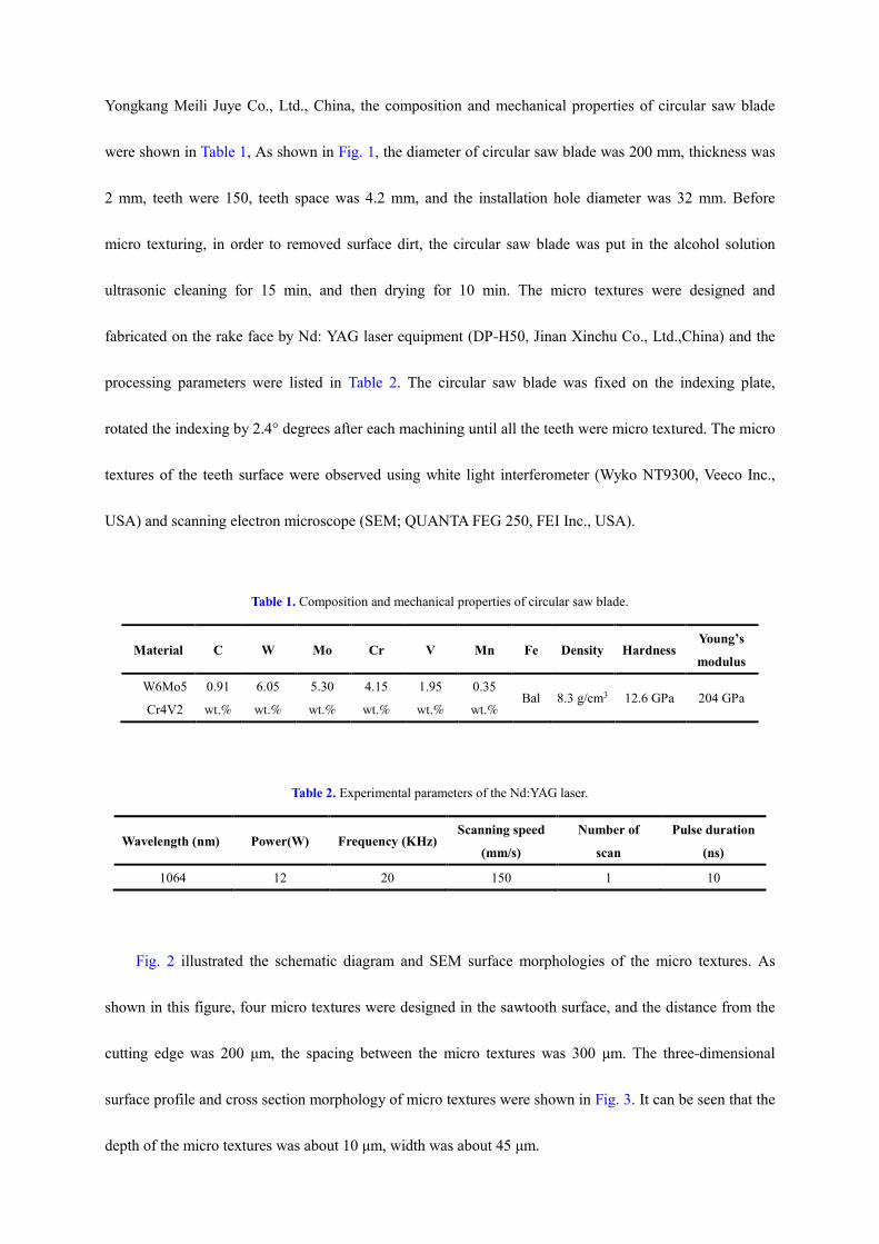
Table 1. Composition and mechanical properties of circular saw blade.
Material C W Mo Cr V Mn Fe Density Hardness Young’s
modulus
W6Mo5
Cr4V2
0.91
wt.%
6.05
wt.%
5.30
wt.%
4.15
wt.%
1.95
wt.%
0.35
wt.% Bal 8.3 g/cm3 12.6 GPa 204 GPa
Table 2. Experimental parameters of the Nd:YAG laser.
Wavelength (nm) Power(W) Frequency (KHz) Scanning speed
(mm/s)
Number of
scan
Pulse duration
(ns)
1064 12 20 150 1 10
Fig. 2 illustrated the schematic diagram and SEM surface morphologies of the micro textures. As
shown in this figure, four micro textures were designed in the sawtooth surface, and the distance from the
cutting edge was 200 μm, the spacing between the micro textures was 300 μm. The three-dimensional
surface profile and cross section morphology of micro textures were shown in Fig. 3. It can be seen that the
depth of the micro textures was about 10 μm, width was about 45 μm.

Fig. 1 The photographs and SEM micrographs of a circular saw blade: (a) photographs of circular saw blade;
(b) rake face of the sawtooth; (c) side morphology of the sawtooth.
Fig. 2 The sawtooth with micro textures: (a) Schematic diagram of the rake face micro textures; (b) SEM image of textured
surface.
Fig. 3 Surface morphology and geometry of the texture: (a) 3D optical micrographs of one micro-groove; (b) section profile
of the micro-groove.

2.2. Sawing tests
Fig. 4 showed the photos of sawing tests that executed with turning machine CKD6150H. The circular
saw blade was mounted on the spindle of the machine tool and with the following geometry: rake angle γ =
−15°, sawing width d =2 mm. Two kinds of circular saw blade were prepared: the micro textured was
fabricated on the rake face of the sawtooth (named TCS), and the conventional circular saw blade with the
same composition was also employed (named CS) for the purpose of comparison. The 304 stainless steel
pipes were employed as the workpiece material with the diameter of 30 mm and the wall thickness of 2 mm.
The 304 stainless steel pipes were installed and fixed on the tool rest and fed along the Y-axis at a certain
rate. The entire process of TCS and CS circular saw blades sawing tests were under the emulsified cutting
fluids (solcut oil-V600, DOMINO Co., Ltd., China) and the sawing conditions were shown in Table 3.
Table 3. Some parameters of the sawing tests.
Feed rate (f) 0.4, 0.6, 0.8, 1.0, 1.2 mm/r
Cutting speed (v) 50, 100, 150 m/mim
Workpiece 304 stainless steel pipe
Cutting tool High speed steel W6Mo5Cr4V2
Sawing machine CKD6150H
Fig. 4 The photos of sawing 304 steel pipes tests.

The sawing forces were recorded by piezoelectric dynamometer Kistler 9275A. The sawing
temperature was measured by an infrared thermal imager (Fotric 225/226) when the circular saw blade
sawing 304 stainless steel pipes. The surface and side worn morphologies of sawtooth were investigated by
scanning electron microscope (SEM; QUANTA FEG 250, FEI Inc., USA), energy-dispersive X-ray
spectroscope (EDS, QUANTA FEG 250, FEI Inc., USA) and optical microscope (VK-X200, KEYENCE
Co., Ltd., China). In addition, the measurement of the average machined surface roughness Ra was
conducted at three different locations by a roughness tester (TR200, JITAIKEYI Inc., China).
3. Results and discussion
3.1. Sawing arc length
The schematic diagram of sawing force was showed in Fig. 5 (a). In this work, the sawing force was
affected by the sawing force per tooth, sawing arc length and teeth space. The sawing force F and sawing
arc length L were obtained from the following equations:
P LF
t
g (1)
1 1
1 1 1 1
arcsin( / 2 ) 0 or 2 290
arcsin( / 2 ) arcsin( / 2 )2
90
R x Rm R m R
LR x R x R
m R m
( , )
( )
(2)
1 1
1
/ 2 ( / 2) ( / 2) / 22 0 2
R R R Rx R
R R
g g g( ) ( ) (3)
1 11
1
/ 2 ( / 2) ( / 2) / 22 2
R r R rx m R m
R r
g g g( ) ( ) (4)
Where sawing force F was the sum of main force Fz and radial thrust force Fy, P was the sawing force per
tooth, L was sawing arc length, and t was the teeth space, R1 was the diameter of circular saw blade, R was
external diameter of the workpiece, r was inside diameter of the workpiece, m was wall thickness, λ was the
sawing depth.

In the sawing process, the teeth space t and the sawing force of each tooth P were constant, so the
sawing force was proportional to the sawing arc length. The variation of sawing arc length was showed in
Fig. 5 (b). When the sawing depth increased from 0 to 2 mm, the sawing arc length was increased rapidly,
from 0 to about 14 mm. Then, the sawing arc length began to decrease and remain stably about 4 mm with
the increasing of sawing depth. Subsequently, the sawing arc length began to increase again, and the sawing
arc length reached the maximum at the sawing depth of 28 mm, which was about 16 mm. Finally, the
sawing arc length rapidly decreased to 0 mm.
Fig. 5 The schematic diagram of sawing force and variation of sawing arc length: (a) schematic diagram; (b) sawing arc
length.
3.2. Sawing force
The effect of the sawing speed and feed rate on the sawing force (main force Fz, and radial thrust force
Fy) for TCS and CS circular saw blade were analyzed. Fig. 6 illustrated the variation of sawing force at
sawing speed 50 m/min and feed rate 0.8 mm/r. For CS circular saw blade, the variation of main force Fz
was increased sharply from 0 to about 270 N before 2 s. Then Fz decreased quickly and reached the
minimum value about 95 N at 8 s. Afterwards, Fz began to increased and reached the maximum value
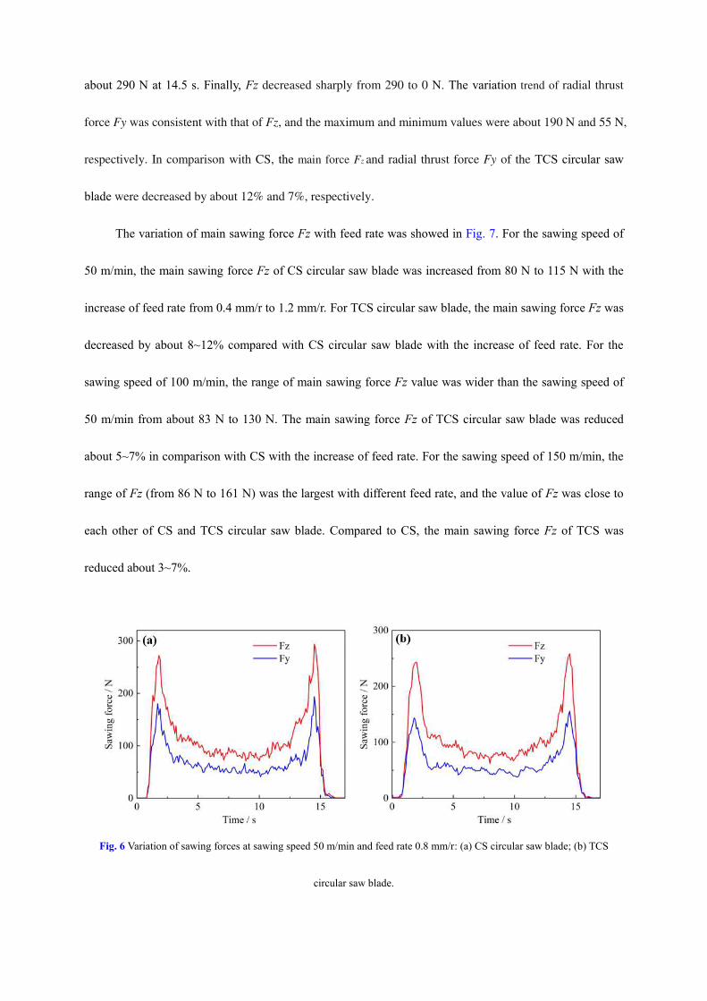
about 290 N at 14.5 s. Finally, Fz decreased sharply from 290 to 0 N. The variation trend of radial thrust
force Fy was consistent with that of Fz, and the maximum and minimum values were about 190 N and 55 N,
respectively. In comparison with CS, the main force Fz and radial thrust force Fy of the TCS circular saw
blade were decreased by about 12% and 7%, respectively.
The variation of main sawing force Fz with feed rate was showed in Fig. 7. For the sawing speed of
50 m/min, the main sawing force Fz of CS circular saw blade was increased from 80 N to 115 N with the
increase of feed rate from 0.4 mm/r to 1.2 mm/r. For TCS circular saw blade, the main sawing force Fz was
decreased by about 8~12% compared with CS circular saw blade with the increase of feed rate. For the
sawing speed of 100 m/min, the range of main sawing force Fz value was wider than the sawing speed of
50 m/min from about 83 N to 130 N. The main sawing force Fz of TCS circular saw blade was reduced
about 5~7% in comparison with CS with the increase of feed rate. For the sawing speed of 150 m/min, the
range of Fz (from 86 N to 161 N) was the largest with different feed rate, and the value of Fz was close to
each other of CS and TCS circular saw blade. Compared to CS, the main sawing force Fz of TCS was
reduced about 3~7%.
Fig. 6 Variation of sawing forces at sawing speed 50 m/min and feed rate 0.8 mm/r: (a) CS circular saw blade; (b) TCS
circular saw blade.

Fig. 7 The variation of main sawing force Fz with feed rate: (a) sawing speed 50 m/min; (b) sawing speed 100 m/min; (c)
sawing speed 150 m/min.
3.3. Sawing temperature
During the sawing process, a lot of energy would be involved for chip removal, which would generate
considerable amounts of heat. In this work, the influence of sawing speed and feed rate on the sawing
temperature for CS and TCS circular saw blade were evaluated under lubrication condition. Fig. 8
illustrated the sawing temperature of CS and TCS circular saw blade under the condition of sawing speed
100 m/min and feed rate 1.2 mm/r. It can be seen that the temperature of the cutting position and the
circumferential of the circular saw blade were higher. For TCS circular saw blade, the sawing temperature
was decreased by about 6.8 % in comparison with the CS circular saw blade.
The contour map of the sawing temperature of CS and TCS circular saw blade with different sawing

speed and feed rate was exhibited in Fig. 9. For the sawing speed of 50, 100 and 150 m/min, the sawing
temperature of CS was increased from about 109 to 196 ℃, 120 to 229 ℃ and 137 to 320 ℃, respectively
with the increase of feed rate from 0.4 to 1.2 mm/r. For the TCS circular saw blade, the sawing temperature
was decreased about 6~14 % under different sawing speed and feed rate in contrast with that of the CS
circular saw blade. The emulsified cutting fluids can penetrate into the tool-chip contact area through the
micro textures resulted in better lubrication and cooling, and thereby reduced the cutting temperature.
Fig. 8 The sawing temperature under the condition of sawing speed 100 m/min and feed rate 1.2 mm/r: (a) CS circular saw
blade; (2) TCS circular saw blade.
Fig. 9 The contour map of the sawing temperature with different sawing speed and feed rate: (a) CS circular saw blade; (b)
TCS circular saw blade.

3.4. Machined surface roughness
The machined surface roughness Ra of the workpiece was measured and presented in Fig. 10. An
increase of feed rate and sawing speed lead to the increase of surface roughness Ra. The machined surface
roughness Ra of the workpiece was range from about 1.7 μm to 8.2 μm under different sawing conditions.
When the sawing speed was 50 m/min, the machined surface roughness Ra was increased from about 1.78
μm to 3.41μm with the increase of feed rate by CS circular saw blade. For TCS circular saw blade, the
machined surface roughness was decreased about 1% ~ 5% in comparison with CS circular saw blade.
When the sawing speed was 100 m/min, the machined surface roughness was increased from about 1.35
μm to 3.31 μm with the increase of feed rate and reduced about 5% ~ 12% compared with CS circular saw
blade. When the sawing speed was 150 m/min, the worn of CS and TCS circular saw blade were serious
and the machined surface roughness changed greatly from about 3.31 μm to 8.19 μm. For TCS circular saw
blade, the machined surface roughness was reduced about 4% ~ 5% compared with CS circular saw blade.
Fig. 10 The variation of machined surface roughness with feed rate: (a) sawing speed 50 m/min; (b) sawing speed 100 m/min;
(c) sawing speed 150 m/min.

3.5. Morphology of machined surface
The machined surface roughness and burrs were important factors affected the quality of steel pipe
machining. The morphology of machined surface by CS and TCS circular saw blade at feed rate 1.2 mm/r
and different sawing speed were showed in Fig. 11 and Fig. 12, respectively. For CS circular saw blade,
some abrasive marks, burrs and adhesions were formed on the machined surface at the sawing speed 50
m/min (Fig. 11(a) and (b)). When the sawing speed was 100 m/min, the height of burrs on the inner side
machined surface of the steel pipe was higher (Fig. 11(c)). Fig. 11(d) showed the machined surface
roughness was increased significantly, and a large number of adhesions and cracks were appeared.
Fig. 11 The morphology of machined surface by CS circular saw blade at feed rate 1.2 mm/r: (a), (b) sawing speed 50 m/min;
(c), (d) sawing speed 100 m/min.
For TCS circular saw blade, the number and height of burrs on the inner side machined surface of the
steel pipe were reduced compared with CS circular saw blade. When the sawing speed was 50 m/min, some
lamellar adhesions and ploughs appeared on the machined surface, and the burrs mainly existed in the inner

machined surface of the steel pipe (Fig. 12(a) and (b)). For the sawing speed 100 m/min, the height of the
burrs and the surface roughness were higher in contrast to the low sawing speed (50 m/min), in addition,
some cracks and ploughs exposed on the machined surface (Fig. 12(c) and (d)).
Fig. 12 The morphology of machined surface by TCS circular saw blade at feed rate 1.2 mm/r: (a), (b) sawing speed 50
m/min; (c), (d) sawing speed 100 m/min.
3.6. Cutter worn characteristics
The worn of the tool surface was mainly caused by the physical and chemical reaction between the
chip material and the circular saw blade material. Fig. 13 exhibited the worn surface morphologies and
corresponding EDS maps of the CS circular saw blade after sawing 15 times 304 stainless steel pipes with
cutting fluid lubrication at different sawing speed (50-150 m/min) and feed rate (0.4-1.2 mm/r). The
morphologies results suggested that many lamellar chips and wear debris adhesive to the worn surface of
the CS circular saw blade. The worn of the sawtooth sawing edge was seriously, and the corners on the both
sides had been worn out, and showed an arc shape as shown in Fig. 13 (a) and (b). In addition, the chip was

seriously piled up at the corners of the sawtooth, and deformed severely. Fig. 13 (c) illustrated the shape of
the chip adhesive on the sawtooth, it can be revealed that the force, extrusion and deformation of the
workpiece material removal in the sawing process. The corresponding EDS maps of the sawtooth worn
surface were shown in Fig. 13 (d-g). It can be seen that the whole sawtooth worn surface was covered with
Ni element because the workpiece material adhesive to the surface during the sawing process. The material
of circular saw blade and workpiece didn’t contain Na element, however, the emulsified cutting fluid
contained Na element. Fig. 13 (f) illustrated Na element was also observed to the sawing zone and played a
lubrication and cooling effect during the sawing progress. In addition, oxidation occurred on the sawtooth
worn surface (Fig. 13 (g)). As mentioned above, although the emulsified cutting fluid can play a lubrication
and cooling role, the severe adhesion and oxidation wear occurred on the sawtooth worn surface.
The worn surface morphologies and corresponding EDS maps of the TCS circular saw blade after
sawing 15 times 304 stainless steel pipes with cutting fluid lubrication at different sawing speed and feed
rate were shown in Fig. 14. A small amount of worn and adhesion of TCS sawtooth surface were showed in
Fig. 14 (a) in comparison with CS circular saw blade. Micro textures still existed on the sawtooth surface
and some adhesions appeared on the side of the micro textures away from the edge (Fig. 14 (b)). The
results showed that the cutting fluid can penetrate into the sawtooth-chip friction contact zone through the
micro textures, thus reducing the sawing temperature and adhesion of the worn surface. Fig. 14 (c)
illustrated the worn and adhesion of the sawtooth corners on the both side were reduced compared to CS.
The corresponding EDS maps of the TCS circular saw blade worn surface were observed and showed in
Fig. 14 (d-g). The results showed that the adhesion of the workpiece material also covered whole sawtooth
surface, and the serious adhesion occurred on the corners of the sawtooth edge. The distribution of the Na
element was observed in Fig.14 (f) further demonstrated that the cutting fluid successfully penetrated into
the sawtooth-chip frictional contact zone during the sawing process. Furthermore, Fig.14 (g) illustrated that

the oxidative worn occurred in the contact area of the sawtooth surface.
Fig. 13 The worn surface morphologies and corresponding EDS maps of the CS circular saw blade: (a)-(c) SEM images of
the worn surface; (d) Fe element; (e) Ni element; (d) Na element; (d) O element.
Fig. 14 The worn surface morphologies and corresponding EDS maps of the TCS circular saw blade: (a)-(c) SEM images of
the worn surface; (d) Fe element; (e) Ni element; (d) Na element; (d) O element.

4. Discussion
The friction and lubricating behavior of the tool-chip interface would affect tool life and machined
surface quality. In this work, the micro textures were fabricated on the tool-chip contact interface, and the
performance of micro textured circular saw blade (TCS) in sawing 304 stainless steel pipes under different
sawing speed and feed rate with fluid lubrication. The friction force (Ff) can be calculated from the
following equation [29]:
f w f c
F a l (5)
Where aw was the cut width, lf was the tool-chip contact length, and τc was the average shear strength at the
tool-chip interface. The resultant force Fr, main sawing force Fz and thrust force Fy of each tooth were
obtained from the following equations:
/ sin
sinw f c
r f
a lF F
(6)
0z 0
cos( ) cos( )
sinw f c
r
a lF F
(7)
0y 0
sin( ) sin( )
sinw f c
r
a lF F
(8)
Where β was the friction angle and γo was the rake angle.
Eqs. (6), (7) and (8) indicated that Fr, Fz, and Fy were linearly related to the cut width aw, tool-chip
contact length lf and average shear strength at the sawtooth-chip interface τc. As shown in Fig. 6 and 7, the
sawing force (main sawing force Fz and thrust force Fy) of TCS circular saw blade was reduced compared
to CS circular saw blade. It can be attributed two mainly aspects: on the one hand, the tool-chip contact
length lf (Fig. 14) of the TCS circular saw blade was decreased in comparison with CS, which was mainly
due to the fabrication of micro textures on the sawtooth surface [22,24,30]. And the effective tool-chip
contact length lt of TCS circular saw blade can be calculated as:

t f tl l nd (9)
where dt was the width of the micro texture and n was the texture quantity in the effective contact zone. On
the other hand, in the sawing process of circular saw blade (CS), due to the high pressure and temperature
of the sawtooth-chip interface, only little cutting fluid penetrated into the friction and contact zone [22,31].
However, the cutting fluid penetrated into the interface of sawtooth and chip through micro textures and
formed a stable lubrication film. Thus average shear strength at the sawtooth-chip interface τc of TCS
circular saw blade was reduced in comparison with CS. As mentioned above, the sawing force of TCS
circular saw blade was reduced on account of the combined effect of micro textures under the lubrication
condition of cutting fluid.
Fig. 15 The distribution schematic diagram of cutting fluid on the sawtooth-chip interface.
Furthermore, the micro textures made the cutting fluid penetrated into the sawtooth-chip interface
easier and reduced the effective contact zone, which will effective reduced the sawing force, sawing
temperature, machined surface roughness and decreased the sawtooth wear. The pressure in the micro
textures was lower than the external pressure and the cutting fluid actively flowed into micro textures,
which mainly due to the chip flowed on the sawtooth surface with high speed. Then, the cutting fluid

flowed out from the micro-texture, and formed a stable lubrication film on the sawtooth-chip interface as
shown in Fig. 15. In consequence, the macro textured circular saw blade (TCS) exhibited a better cutting
performance in comparison with traditional circular saw blade (CS). In addition, Fig. 13 and 14 illustrated
the wear and adhesion of TCS circular saw blade after sawing 304 stainless steel pipes 15 times were
relatively reduced compared to CS.
The cutting performance of micro textured circular saw blade was improved effectively, owing to
decreasing the tool-chip contact length, sawing force and sawing temperature, reducing the wear and
adhesion of the sawtooth surface, and improving the quality of the machined surface. However, the worn
on the corners of the sawtooth edge was seriously, and the sustainability of high speed steel sawtooth need
to be improved.
5. Conclusions
In this paper, linear micro textures that parallel to the sawtooth edge were fabricated on the surface of
the high speed steel W6Mo5Cr4V2 circular saw blade. Sawing 304 stainless steel pipes tests were carried
out with the micro textured circular saw blade (TCS) under the lubrication condition. The following
conclusions can be obtained:
(1) The largest sawing arc length and sawing force were occurred on the circular saw blade sawing
outward from the inner wall. Then, the second largest sawing arc length and force appeared on the
circular saw blade first contact with the inner wall. When the circular saw blade was sawing to middle
position of the pipes, the sawing arc length and sawing force were smaller and more stable.
(2) In the sawing process, micro textured circular saw blade (TCS) showed better cutting performance in
comparison with traditional circular saw blade (CS) in terms of (i) reduced cutting forces and cutting

temperatures, (ii) improved the quality of machined surface and decreased the number of burrs, (iii)
reduced the wear and adhesion of sawtooth surface.
(3) The coupling effect mechanisms were found, on the one hand, the effective sawtooth-chip contact
length was reduced due to the micro textures fabricated on the sawtooth surface, on the other hand,
cutting fluid can be better penetrated into the micro textures and formed stable lubrication film in
sawtooth-chip contact interface.
Ethical approval
The authors declare that this manuscript was not submitted to more than one journal for simultaneous
consideration. Also, the submitted work is original and not have been published elsewhere in any form or
language.
Consent to participate and publish
The authors declare that they participated in this paper willingly and the authors declare to consent to the
publication of this paper.
Authors Contributions
Yang Lu: Formal analysis, Methodology, Data curation, Writing original draft. Jianxin Deng:
Conceptualization, Supervision. Qinghao Sun: Supervision. Dongliang Ge: Investigation. Jiaxing Wu and
Zhihui Zhang: Writing-review & editing.
Acknowledgements
This work is supported by the Key Research and Development Projects of Shandong Province
(2019TSLH0315) and the National Natural Science Foundation of China (51675311).

Conflict of interests
The authors declare that there is no conflict of interests regarding the publication of this paper.
Availability of data and materials
The authors declare that data and materials are authentic and available.
Reference
1. Junz Wang J-J, Wu S-H, Lee R-S (2012) Chip fractal geometry and loading characteristics of sinusoidal
multi-cutters in hack-sawing process. Int J Mach Tools Manuf 59:65–80.
https://doi.org/https://doi.org/10.1016/j.ijmachtools.2012.01.005
2. Söderberg S, Åhman L, Svenzon M (1983) A metallurgical study of the wear of band-saw blades. Wear 85:11–27.
https://doi.org/https://doi.org/10.1016/0043-1648(83)90332-0
3. Ko TJ, Kim HS (1999) Mechanistic cutting force model in band sawing. Int J Mach Tools Manuf 39:1185–1197.
https://doi.org/https://doi.org/10.1016/S0890-6955(98)00087-X
4. Nishio S, Marui E (1996) Effects of slots on the lateral vibration of a circular saw blade. Int J Mach Tools Manuf
36:771–787. https://doi.org/https://doi.org/10.1016/0890-6955(95)00088-7
5. Lewis DB, Bradbury SR, Sarwar M (1996) The effect of substrate surface preparation on the wear and failure modes
of TiN coated high speed steel circular saw blades. Wear 197:82–88.
https://doi.org/https://doi.org/10.1016/0043-1648(95)06835-X
6. Chang WT, Chen LC (2016) Design and experimental evaluation of a circular saw blade with self-clamped cutting
inserts. Int J Adv Manuf Technol 83:365–379. https://doi.org/10.1007/s00170-015-7563-7
7. Bradbury SR, Lewis DB (2000) Comparison of the performance and wear characteristics of high-speed steel circular

saw blades machining Nimonic PK31, AISI O1 Tool Steel, Inconel 600L, and AISI 1018 Carbon Steel. J Mater Sci
35:1511–1524. https://doi.org/10.1023/A:1004749400522
8. Chang WT, Su CH, Guo DX, et al (2013) Automated optical inspection for the runout tolerance of circular saw
blades. Int J Adv Manuf Technol 66:565–582. https://doi.org/10.1007/s00170-012-4350-6
9. Beljo-Lučić R, Goglia V (2001) Some possibilities for reducing circular saw idling noise. J Wood Sci 47:389–393.
https://doi.org/10.1007/BF00766791
10. Alam MT, Kinoshita N, Tanaka C, Yoshinobu M (2002) Circular saw lateral stability by optimization of feed speed.
Holz als Roh - und Werkst 60:207–209. https://doi.org/10.1007/s00107-002-0286-0
11. Nasir V, Mohammadpanah A, Cool J (2020) The effect of rotation speed on the power consumption and cutting
accuracy of guided circular saw: Experimental measurement and analysis of saw critical and flutter speeds. Wood
Mater Sci Eng 15:140–146. https://doi.org/10.1080/17480272.2018.1508167
12. Vladescu S-C, Olver A V, Pegg IG, Reddyhoff T (2015) The effects of surface texture in reciprocating contacts –
An experimental study. Tribol Int 82:28–42. https://doi.org/https://doi.org/10.1016/j.triboint.2014.09.015
13. Vlădescu S-C, Olver A V, Pegg IG, Reddyhoff T (2016) Combined friction and wear reduction in a reciprocating
contact through laser surface texturing. Wear 358–359:51–61.
https://doi.org/https://doi.org/10.1016/j.wear.2016.03.035
14. Biboulet N, Bouassida H, Lubrecht AA (2015) Cross hatched texture influence on the load carrying capacity of oil
control rings. Tribol Int 82:12–19. https://doi.org/https://doi.org/10.1016/j.triboint.2014.09.024
15. Segu DZ, Choi SG, Choi J hyouk, Kim SS (2013) The effect of multi-scale laser textured surface on lubrication
regime. Appl Surf Sci 270:58–63. https://doi.org/https://doi.org/10.1016/j.apsusc.2012.12.068
16. Shen C, Khonsari MM (2016) The effect of laser machined pockets on the lubrication of piston ring prototypes.
Tribol Int 101:273–283. https://doi.org/https://doi.org/10.1016/j.triboint.2016.04.009
17. Wang T, Huang W, Liu X, et al (2014) Experimental study of two-phase mechanical face Seals with laser surface

texturing. Tribol Int 72:90–97. https://doi.org/https://doi.org/10.1016/j.triboint.2013.12.009
18. Tala-Ighil N, Fillon M (2015) Surface texturing effect comparative analysis in the hydrodynamic journal bearings.
Mech Ind 16:. https://doi.org/10.1051/meca/2015001
19. Ibatan T, Uddin MS, Chowdhury MAK (2015) Recent development on surface texturing in enhancing tribological
performance of bearing sliders. Surf Coatings Technol 272:102–120.
https://doi.org/https://doi.org/10.1016/j.surfcoat.2015.04.017
20. Duan R, Deng J, Lei S, et al (2019) Effect of derivative cutting on machining performance of micro textured tools. J
Manuf Process 45:544–556. https://doi.org/https://doi.org/10.1016/j.jmapro.2019.07.037
21. Gropper D, Wang L, Harvey TJ (2016) Hydrodynamic lubrication of textured surfaces: A review of modeling
techniques and key findings. Tribol Int 94:509–529. https://doi.org/https://doi.org/10.1016/j.triboint.2015.10.009
22. Ge D, Deng J, Duan R, et al (2019) Effect of micro-textures on cutting fluid lubrication of cemented carbide tools.
Int J Adv Manuf Technol 103:3887–3899. https://doi.org/10.1007/s00170-019-03763-6
23. Kawasegi N, Sugimori H, Morimoto H, et al (2009) Development of cutting tools with microscale and nanoscale
textures to improve frictional behavior. Precis Eng 33:248–254.
https://doi.org/https://doi.org/10.1016/j.precisioneng.2008.07.005
24. Jianxin D, Ze W, Yunsong L, et al (2012) Performance of carbide tools with textured rake-face filled with solid
lubricants in dry cutting processes. Int J Refract Met Hard Mater 30:164–172.
https://doi.org/https://doi.org/10.1016/j.ijrmhm.2011.08.002
25. Neves D, Diniz AE, de Lima MSF (2006) Efficiency of the laser texturing on the adhesion of the coated twist drills.
J Mater Process Technol 179:139–145. https://doi.org/https://doi.org/10.1016/j.jmatprotec.2006.03.068
26. Li Q, Yang S, Zhang Y, et al (2018) Evaluation of the machinability of titanium alloy using a micro-textured ball
end milling cutter. Int J Adv Manuf Technol 98:2083–2092. https://doi.org/10.1007/s00170-018-2319-9
27. Zhou C, Guo X, Zhang K, et al (2019) The coupling effect of micro-groove textures and nanofluids on cutting

performance of uncoated cemented carbide tools in milling Ti-6Al-4V. J Mater Process Technol 271:36–45.
https://doi.org/https://doi.org/10.1016/j.jmatprotec.2019.03.021
28. Ling TD, Liu P, Xiong S, et al (2013) Surface texturing of drill bits for adhesion reduction and tool life enhancement.
Tribol Lett 52:113–122. https://doi.org/10.1007/s11249-013-0198-7
29. Cheng RY (1992) Principle of metal cutting, first edn. China Machine Press, Beijing.
30. Song W, Wang S, Lu Y, Xia Z (2018) Tribological performance of microhole-textured carbide tool filled with CaF2.
Materials (Basel) 11:. https://doi.org/10.3390/ma11091643
31. Thepsonthi T, Hamdi M, Mitsui K (2009) Investigation into minimal-cutting-fluid application in high-speed milling
of hardened steel using carbide mills. Int J Mach Tools Manuf 49:156–162.
https://doi.org/https://doi.org/10.1016/j.ijmachtools.2008.09.007

Figures
Figure 1
The photographs and SEM micrographs of a circular saw blade: (a) photographs of circular saw blade;(b) rake face of the sawtooth; (c) side morphology of the sawtooth.

Figure 2
The sawtooth with micro textures: (a) Schematic diagram of the rake face micro textures; (b) SEM imageof textured
Figure 3
Surface morphology and geometry of the texture: (a) 3D optical micrographs of one micro-groove; (b)section pro�le of the micro-groove.

Figure 4
The photos of sawing 304 steel pipes tests.

Figure 5
The schematic diagram of sawing force and variation of sawing arc length: (a) schematic diagram; (b)sawing arc length.
Figure 6
Variation of sawing forces at sawing speed 50 m/min and feed rate 0.8 mm/r: (a) CS circular saw blade;(b) TCS circular saw blade.

Figure 7
The variation of main sawing force Fz with feed rate: (a) sawing speed 50 m/min; (b) sawing speed 100m/min; (c) sawing speed 150 m/min.

Figure 8
The sawing temperature under the condition of sawing speed 100 m/min and feed rate 1.2 mm/r: (a) CScircular saw blade; (2) TCS circular saw blade.
Figure 9
The contour map of the sawing temperature with different sawing speed and feed rate: (a) CS circularsaw blade; (b) TCS circular saw blade.

Figure 10
The variation of machined surface roughness with feed rate: (a) sawing speed 50 m/min; (b) sawingspeed 100 m/min; (c) sawing speed 150 m/min.

Figure 11
The morphology of machined surface by CS circular saw blade at feed rate 1.2 mm/r: (a), (b) sawingspeed 50 m/min; (c), (d) sawing speed 100 m/min.

Figure 12
The morphology of machined surface by TCS circular saw blade at feed rate 1.2 mm/r: (a), (b) sawingspeed 50 m/min; (c), (d) sawing speed 100 m/min.

Figure 13
The worn surface morphologies and corresponding EDS maps of the CS circular saw blade: (a)-(c) SEMimages of the worn surface; (d) Fe element; (e) Ni element; (d) Na element; (d) O element. Note: Thedesignations employed and the presentation of the material on this map do not imply the expression ofany opinion whatsoever on the part of Research Square concerning the legal status of any country,territory, city or area or of its authorities, or concerning the delimitation of its frontiers or boundaries. Thismap has been provided by the authors.

Figure 14
The worn surface morphologies and corresponding EDS maps of the TCS circular saw blade: (a)-(c) SEMimages of the worn surface; (d) Fe element; (e) Ni element; (d) Na element; (d) O element. Note: Thedesignations employed and the presentation of the material on this map do not imply the expression ofany opinion whatsoever on the part of Research Square concerning the legal status of any country,territory, city or area or of its authorities, or concerning the delimitation of its frontiers or boundaries. Thismap has been provided by the authors.

Figure 15
The distribution schematic diagram of cutting �uid on the sawtooth-chip interface.