effect of incidence angle on laser scanner intensity and surface data
TRANSCRIPT
Effect of incidence angle on laser scanner intensityand surface data
Antero Kukko,* Sanna Kaasalainen, and Paula LitkeyDepartment of Remote Sensing and Photogrammetry, Finnish Geodetic Institute, P.O. Box 15, FIN-02431 Masala, Finland
*Corresponding author: [email protected]
Received 23 August 2007; revised 7 December 2007; accepted 4 January 2008;posted 18 January 2008 (Doc. ID 86812); published 29 February 2008
We present a comprehensive experimental set of data on the dependence of the laser intensity on theangle of incidence to the target surface. The measurements have been performed in the laboratory forsamples with aNd:YAG laser and terrestrial laser scanner. The brightness scale data were also comparedwith data acquired by airborne laser scanning (ALS). The incidence angle effect is evident for all thetargets. The effect is significant for incidence angles > 20°, and stronger for bright targets. However,effects due to some of the other surface properties, such as roughness, were also detected. We also founda set of gravel samples for which the incidence angle effect was minor even up to 40°. The data provide animportant reference for the interpretation and applications, e.g., full-waveform data processing of a laserscanner and ALS intensity calibration. © 2008 Optical Society of America
OCIS codes: 280.3640, 280.1350, 290.5820.
1. Introduction
Lidar systems have become a well-established toolfor providing accurate 3D information on remote sen-sing targets. There is abundant knowledge on systemuncertainties and their effect on the topographicmodels, but there are little studies on the role ofthe optical properties of the targets and the laserlight interaction with the surface media. A numberof studies on the light interaction with surfacesand diffusive media are available [1,2] and the effectof the optical properties of different targets on theirbackscatter [3–6]. Simulations on the laser beam in-teraction with the target surface have provided someimportant information on the properties with thestrongest effects on the laser interaction and the in-terpretation of the backscattered pulse [7,8], butthere is a growing need for experimental data onthe factors affecting the laser echo, such as the sur-face composition and structure, and especially theorientation of the target. Systematic experimentaldata on the effect of the incidence (i.e., scanning)angle on the intensity of typical laser scanner land
targets provide an important reference for the inter-pretation and applications, e.g., simulations of full-waveform laser scanner data.
The observing geometry in all the current lidarsystems is basically the same. The returning pulseis recorded practically at backscatter, i.e., the lightpaths of the source and detector coincide. This geo-metry is a source of some important scattering effectsthat are studied in many fields of optics and physics[1,3–6] and references therein, but since the obser-ving geometry remains the same in all lidar applica-tions, the effects from the change of geometry aremostly avoided.
The angle of incidence to the target plays an impor-tant role in both the 3D model and the backscatteredintensity recorded by the lidar sensor. The effectof the incidence angle on backscatter has been ad-dressed computationally and experimentally innumerous works in photonics and optics (e.g.,[1,2,9–11]). These studies have mostly concentratedon specific case studies, e.g., the polarized backscat-ter from diffusive media or fiber on a reflectivesurface [1,2,9,10], but the applications of theseresults to remote sensing of natural surfaces arelimited. No systematic experimental data on the
0003-6935/08/070986-07$15.00/0© 2008 Optical Society of America
986 APPLIED OPTICS / Vol. 47, No. 7 / 1 March 2008
effect of incidence angle on different materials, espe-cially the typical remote sensing targets, are avail-able [1]. Such data would also be important for theinvestigation of a lidar-based reflectance measure-ment, which has recently become a topic of scientificinterest [12–16]. One of the few attempts to correctthe incidence angle effect on lidar intensity is basedon a simple cosine approach where a Lambertiansurface is assumed [17,18].We present a systematic set of data on the depen-
dence of the laser intensity on the angle of incidenceto the target surface. To our knowledge this is thefirst comprehensive study on these effects in the con-text of scanning lidars. Data from independent mea-surement systems [laboratory and terrestrial laserscanner (TLS)] are presented and compared, andthe implications of the results on lidar-derived 3Dmodels (such as the possible empirical correctionsand applications) are discussed.
2. Methods
A. Laboratory Experiment
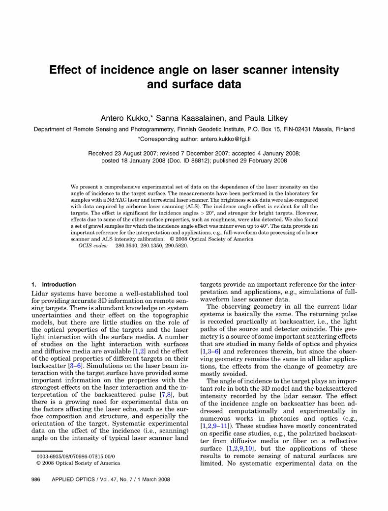
The laboratory laser instrument has been con-structed to operate in the similar illumination/obser-vation geometry as in laser scanning (i.e., exactbackscatter where the source and detector lightpaths coincide). The instrument (sketched in Fig. 1)comprises a 1064nm Nd:YAG laser (wavelengthsimilar to most airborne scanners), and a 16 bitmonochrome CCD camera (Sbig ST-7), which is acommonly used detector in laboratory (laser) mea-surements in, e.g., optical physics [5]. We averagedfive 3 s images for each target. To illuminate an areaof the sample larger than the 3mm laser spot (andhence reduce the deviation in data), the sampleswere placed on a rotator allowing the laser spot tomove around the sample surface during the image
exposures. The backscattered laser intensities weremeasured from the CCD images by means of stan-dard photometric techniques. More details on theexperiment are found in [12,13]. The incidenceangles were changed using a precision goniometerto tilt the sample from normal (0°) incidence (seeFigs. 1 and 2).
To demonstrate the wavelength effects on the inci-dence angle dependence in general, we also carriedout a hyperspectral measurement for some of the tar-gets. The measurement was made similarly to the1064nm experiment (i.e., at the exact backscatterangle) by replacing the Nd:YAG with a superconti-nuum (KOHERAS SuperK RED) laser and installinga spectrograph (Specim ImSpector) in front of theCCD camera. The spectra were measured at thewavelength range of 600–900nm. The instrument
Fig. 1. Laboratory laser (Nd:YAG) measurement arrangement.The sample surface was tilted using a goniometer (see also Fig. 2)to change the incidence angle.
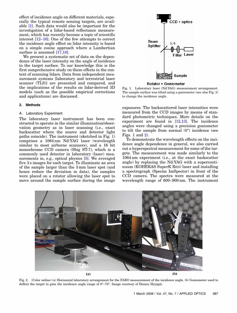
Fig. 2. (Color online) (a) Horizontal laboratory arrangement for the FARO measurement of the incidence angle. (b) Goniometer used todeflect the target to gain the incidence angle range of 0°–70°. Image courtesy of Hannu Hyyppä.
1 March 2008 / Vol. 47, No. 7 / APPLIED OPTICS 987
was similar to that presented in [19] with a betteralignment and thus improved accuracy.
B. Terrestrial and Airborne Laser Scanner Measurements
The validation of the results of the laboratory lasermeasurements was carried out with the FARO LS880HE80 (FARO LS) TLS operating at 785nm.The scanner uses the phase angle technique forthe distance measurement with the accuracy of3–5mm and 360° × 320° field of view. The detectorof the FARO LS is not optimized for intensity mea-surement. There are modifications in the detectorthat affect the intensity, e.g., a brightness reducerfor near distances (< 10m) and a logarithmic am-plifier for small reflectances. These all requiredextensive and systematic distance and reflectancecalibrations, which were carried out in the laboratoryusing a calibrated gray scale and a calibrated four-step Spectralon reflectance panel [12,13]. The inci-dence angle measurements were carried out at a1m target distance placing the sample on the gonio-meter for the incidence angle variation (Fig. 2).Three of the brightness scale targets with 10%,
20%, and 50% nominal reflectances were also mea-sured at the Espoonlahti airborne laser scanning(ALS) flight campaign, conducted 31 August 2006using the TopEye MKII 1064nm laser scanner.The flying altitude was 300m, and the test area con-sisted of the Espoonlahti boat harbor and beach.From each sample, 20–100 hits (i.e., returned pulses)were recorded.
C. Samples
We investigated a set of targets used in ALS inten-sity calibration and a set of natural and artificial(such as brick material) samples representing typicalALS land targets. The brightness calibration targets(tarps) measured in this study have been used inradiometric calibration of aerial cameras and ALSs.The tarps aremade of polyester fiber with a polyvinylchloride (PVC) coating and span a brightness grayscale from 5% to 70% of reflectance [15]. We mea-sured a set of four targets with calibrated reflec-tances of 8%, 26%, 50%, and 70% [12]. All themeasurements are relative to the Spectralon 99%reference target at 0° incidence. The incidence angleeffect of the Spectralon target was also measured.We have also studied the possibility of using stan-
dard industrial gravel in airborne laser scannerintensity calibration [12,13]. A set of gravel withdistinctly different reflectances, small deviation anddifference between laboratory and laser scannermeasurements, and little variation with the mea-surement geometry would be ideal for the purposeof intensity calibration. Preliminary tests haveshown that gravel with uniform color range withrespect to the dimensions of the measurement(i.e., the laser spot/footprint size) are most suitablefor laboratory reference measurements. As thelaboratory brightness calibration is essential forthe use of these gravel as intensity standards in
ALS campaigns, it is important that the resultsare consistent even for the small-scale (laboratory)measurements. The footprint of an airborne laserscanner might allow some larger-scale variationsin the target structure and brightness, but reprodu-cing such results in the laboratory (where a colli-mated laser source is needed to reproduce thebackscatter measurement geometry of laser scan-ners, e.g., [12,13,19]) has proved a challenge.
The sand and gravel chosen for this study are com-monly used in sandblasting and construction. Wemeasured sandblasting sand of two grain sizes, blackgabro gravel, crushed redbrick, and light expandedclay aggregate (LECA), which consists of small, light-weight, bloated particles of burnt clay. These gravelwere also chosen because of their easy availability instandard hardware stores, which would be practicalfor the calibration of airborne laser data taken at dif-ferent campaigns in varying locations. The prelimin-ary test measurements for a large set of gravelshowed that it is difficult to find a gravel of highreflectance suitable for calibration. Therefore, toextend the brightness scale toward higher reflec-tances, we included a sample of polystyrene intothe investigation. As the gravel samples startedspilling at high tilt angles, the measurements over40° of incidence were not practical. To demonstratethe incidence angle effects for natural samples, wealso present a spectral result for a linden (Tilia cor-data) leaf.
3. Results and Discussion
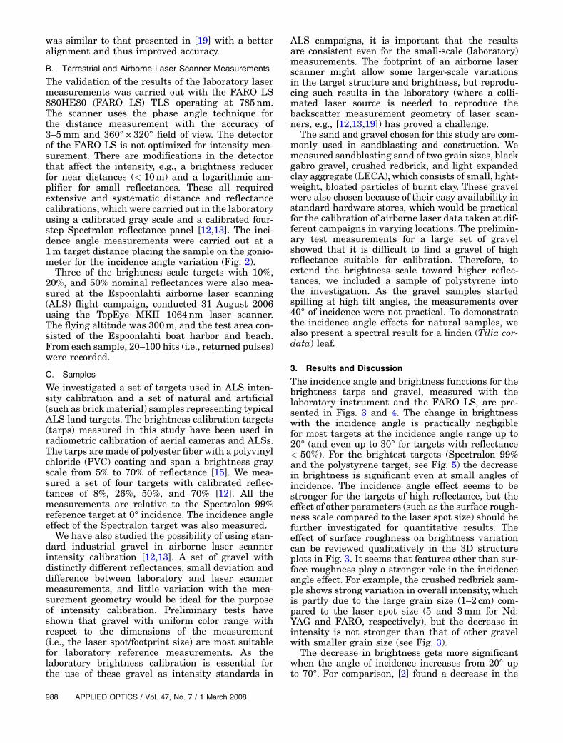
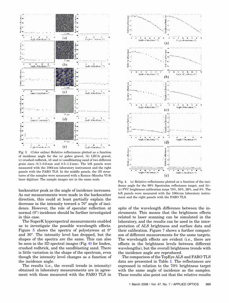
The incidence angle and brightness functions for thebrightness tarps and gravel, measured with thelaboratory instrument and the FARO LS, are pre-sented in Figs. 3 and 4. The change in brightnesswith the incidence angle is practically negligiblefor most targets at the incidence angle range up to20° (and even up to 30° for targets with reflectance< 50%). For the brightest targets (Spectralon 99%and the polystyrene target, see Fig. 5) the decreasein brightness is significant even at small angles ofincidence. The incidence angle effect seems to bestronger for the targets of high reflectance, but theeffect of other parameters (such as the surface rough-ness scale compared to the laser spot size) should befurther investigated for quantitative results. Theeffect of surface roughness on brightness variationcan be reviewed qualitatively in the 3D structureplots in Fig. 3. It seems that features other than sur-face roughness play a stronger role in the incidenceangle effect. For example, the crushed redbrick sam-ple shows strong variation in overall intensity, whichis partly due to the large grain size (1–2 cm) com-pared to the laser spot size (5 and 3mm for Nd:YAG and FARO, respectively), but the decrease inintensity is not stronger than that of other gravelwith smaller grain size (see Fig. 3).
The decrease in brightness gets more significantwhen the angle of incidence increases from 20° upto 70°. For comparison, [2] found a decrease in the
988 APPLIED OPTICS / Vol. 47, No. 7 / 1 March 2008
backscatter peak as the angle of incidence increases.As our measurements were made in the backscatterdirection, this could at least partially explain thedecrease in the intensity toward a 70° angle of inci-dence. However, the role of specular reflection atnormal (0°) incidence should be further investigatedin this case.The SuperK hyperspectral measurements enabled
us to investigate the possible wavelength effects.Figure 5 shows the spectra of polystyrene at 0°and 30°. The intensity level has dropped, but theshapes of the spectra are the same. This can alsobe seen in the 3D spectral images (Fig. 6) for linden,crushed redbrick, and the sandblasting sand. Thereis little variation in the shape of the spectrum, eventhough the intensity level changes as a function ofthe incidence angle.The results (i.e., the overall trends in intensity)
obtained in laboratory measurements are in agree-ment with those measured with the FARO TLS in
spite of the wavelength difference between the in-struments. This means that the brightness effectsrelated to laser scanning can be simulated in thelaboratory, and the results can be used in the inter-pretation of ALS brightness and surface data andtheir calibration. Figure 7 shows a further compari-son of different measurements for the same targets.The wavelength effects are evident (i.e., there areoffsets in the brightness levels between differentwavelengths), but the overall brightness trends withthe incidence angle are reproduced.
The comparison of the TopEye ALS and FARO TLSdata are presented in Table 1. The reflectances areexpressed in relation to the 70% brightness targetwith the same angle of incidence as the samples.These results also point out that the relative results
Fig. 3. (Color online) Relative reflectances plotted as a functionof incidence angle for the (a) gabro gravel, (b) LECA gravel,(c) crushed redbrick, (d) and (e) sandblasting sand of two differentgrain sizes (0:1–0:6mm and 0:5–1:2mm). The left panels weremeasured with the 1064nm laboratory instrument and the rightpanels with the FARO TLS. In the middle panels, the 3D struc-tures of the samples were measured with a Konica–Minolta VI-9ilaser digitizer. The sample images are in the same scale.
Fig. 4. (a) Relative reflectances plotted as a function of the inci-dence angle for the 99% Spectralon reflectance target, and (b)–(e) PVC brightness calibration tarps 70%, 50%, 26%, and 8%. Theleft panels were measured with the 1064nm laboratory instru-ment and the right panels with the FARO TLS.
1 March 2008 / Vol. 47, No. 7 / APPLIED OPTICS 989
are fairly well reproduced at small (up to 20°) anglesof incidence. There are differences between ALS andTLS intensity levels, some of which may be explainedby the difference in wavelength, but much more datafrom ALS campaigns are needed to make a more
accurate comparison and to establish the accuracylimits of ALS intensity measurement [12,13,19].Other important future issues include, e.g., the roleof multiple and specular reflections. Because of thegrainy nature of most of the samples studied here,
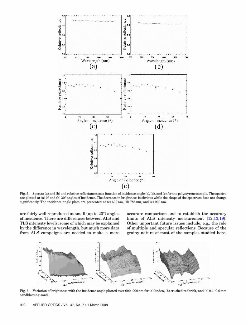
Fig. 5. Spectra (a) and (b) and relative reflectances as a function of incidence angle (c), (d), and (e) for the polystyrene sample. The spectraare plotted at (a) 0° and (b) 30° angles of incidence. The decrease in brightness is obvious while the shape of the spectrum does not changesignificantly. The incidence angle plots are presented at (c) 633nm, (d) 785nm, and (e) 900nm.
Fig. 6. Variation of brightness with the incidence angle plotted over 600–900nm for (a) linden, (b) crushed redbrick, and (c) 0:1–0:6mmsandblasting sand .
990 APPLIED OPTICS / Vol. 47, No. 7 / 1 March 2008
the specular reflections seem to occur in all direc-tions, not only in the normal (0°) incidence.
4. Conclusion
We have investigated the effect of the incidence angleon target brightness. Thus far there has been little ofsuch information available, especially for laser scan-ning applications, where the incidence angle plays acrucial role on the intensity calibration. This studygives an overall view of the incidence angle effectson such targets from a practical point of view. Wehave also carried out a hyperspectral study of theincidence angle effects and demonstrated that theincidence angle effects are consistent between differ-ent wavelengths, although there are changes in theintensity levels of the targets.We found that the decrease in target brightness is
significant mostly at incidence angles > 30°. Theseangles have little relevance in the possible ALSbased radiometric calibration measurement butmust be taken into account in the interpretation of
airborne or TLS data where steep slopes and verticalsurfaces are present in the target area. It also seemsthat the target brightness plays some role in thebrightness decrease, especially toward large (up to70°) angles of incidence.
We also present a set of gravel samples, for whichthe decrease in brightness with the incidence anglewas negligible up to ∼40°. This makes them idealtargets for airborne laser scanner brightness calibra-tion, since the typical incidence (i.e., scanning) anglevariation is usually within this range. The laboratorymeasurements show a gradual increase in the bright-ness for these targets, which provide us a field bright-ness scale from 0.1 to 0.5. In adding a sample ofpolystyrene to the set of gravel, the scale can beextended up to 0.8.
The incidence angle data derived in this study areto be applied in the data analysis for scanning lidarsensors. The incidence angle strongly affects theachievable range accuracy, as the shape of the de-tected echo (of the transmitted pulse) changes with
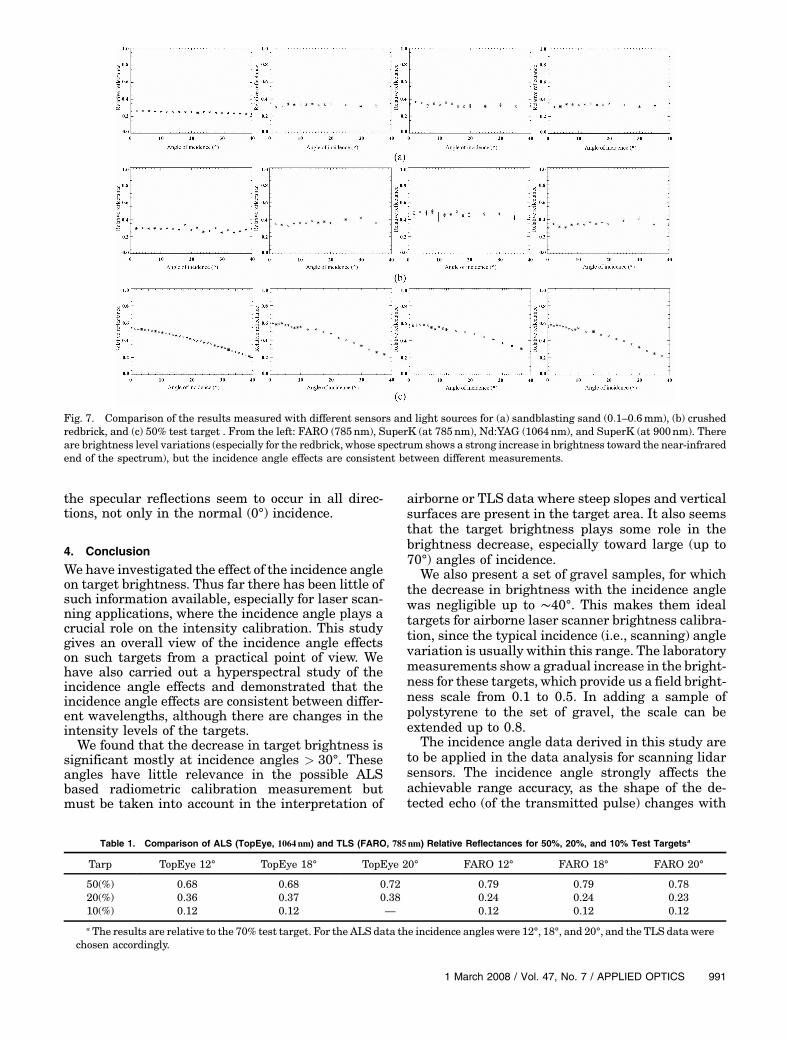
Fig. 7. Comparison of the results measured with different sensors and light sources for (a) sandblasting sand (0:1–0:6mm), (b) crushedredbrick, and (c) 50% test target . From the left: FARO (785nm), SuperK (at 785nm), Nd:YAG (1064nm), and SuperK (at 900nm). Thereare brightness level variations (especially for the redbrick, whose spectrum shows a strong increase in brightness toward the near-infraredend of the spectrum), but the incidence angle effects are consistent between different measurements.
Table 1. Comparison of ALS (TopEye, 1064 nm) and TLS (FARO, 785 nm) Relative Reflectances for 50%, 20%, and 10% Test Targetsa
Tarp TopEye 12° TopEye 18° TopEye 20° FARO 12° FARO 18° FARO 20°
50(%) 0.68 0.68 0.72 0.79 0.79 0.7820(%) 0.36 0.37 0.38 0.24 0.24 0.2310(%) 0.12 0.12 — 0.12 0.12 0.12
a The results are relative to the 70% test target. For the ALS data the incidence angles were 12°, 18°, and 20°, and the TLS datawerechosen accordingly.
1 March 2008 / Vol. 47, No. 7 / APPLIED OPTICS 991
the angle of incidence, unless proper signal proces-sing algorithms are used as discussed in [20,21]. Itis also expected that the laser scanner data couldbe further analyzed if such sources of variation areproperly understood. Incidence angle data arefurthermore essential in establishing a simulationmodel for laser scanning as proposed by [7]. As thesystematic experimental data on incidence angleeffects are still in sparse supply, our results applydirectly to the optical studies of directional lightscattering.
The authors thank Altti Akujärvi for laboratoryassistance and Hannu Hyyppä at Helsinki Univer-sity of Technology for support, photographs, andthe bulk of music to make the measurements morecomfortable.
References1. J. Ellis, P. Caillard, and A. Dogariu, “Off-diagonal Mueller ma-
trix elements in backscattering from highly diffusive media,”J. Opt. Soc. Am. A 19, 43–48 (2002).
2. V. A. Ruiz-Cortés and J. C. Dainty, “Experimental light-scat-tering measurements for large-scale composite random roughsurfaces,” J. Opt. Soc. Am. A 19, 2043–2052 (2002).
3. M. P. van Albada and A. Lagendijk, “Observation of weaklocalization of light in a random medium,” Phys. Rev. Lett.55, 2692–2695 (1985).
4. D. S. Wiersma, M. P. van Albada, B. A. van Tiggelen, andA. Lagendijk, “Experimental evidence for recurrent multiplescattering events of light in disordered media,” Phys. Rev.Lett. 74, 4193–4196 (1995).
5. G. D. Yoon, N. G. Roy, and R. C. Straight, “Coherent backscat-tering in biological media: measurement and estimation ofoptical properties,” Appl. Opt. 32, 580–585 (1993).
6. S. Kaasalainen, J. Peltoniemi, J. Näränen, J. Suomalainen,F. Stenman, and M. Kaasalainen, “Small-angle goniometryfor backscattering measurements in the broadband spec-trum,” Appl. Opt. 44, 1485–1490 (2005).
7. A. Kukko and J. Hyyppä, “Laser scanner simulator for systemanalysis and algorithm development: a case with forest mea-surements,” in Proceedings of the ISPRS Workshop on LaserScanning 2007 and SilviLaser 2007 Espoo, 12–14 Septem-ber 2007, Finland; International Archives of Photogrammetry,Remote Sensing, and Spatial Information Sciences 36, Part 3/W52, 234–240 (2007).
8. B. Jutzi, J. Neulist, and U. Stilla, “High-resolution waveformacquisition and analysis for pulsed laser,” in High-ResolutionEarth Imaging for Geospatial Information, C. Heipke, K.Jacobsen, and M. Gerke, eds., International Archives ofPhotogrammetry, Remote Sensing, and Spatial InformationSciences 36, Part 1/W3, CD-ROM (2005).
9. G. Videen, W. S. Bickel, V. J. Iafelice, and D. Abromson,“Experimental light-scattering Mueller matrix for a fiber ona reflecting optical surface as a function of incident angle,”J. Opt. Soc. Am. A 9, 312–315 (1992).
10. J. P. Landry, J. Gray, M. K. O’Toole, and X. D. Zhu, “Incidence-angle dependence of optical reflectivity difference froman ultrathin film on solid surface,” Opt. Lett. 31, 531–533(2006).
11. B. Jutzi, B. Eberle, and U. Stilla, “Estimation and measure-ment of backscattered signals from pulsed laser radar,” Proc.SPIE 4885, 256–267 (2003).
12. S. Kaasalainen, A. Kukko, T. Lindroos, P. Litkey, H. Kaarti-nen, J. Hyyppä, and E. Ahokas, “Brightness measurementsand calibration with airborne and terrestrial laser scanners,”IEEE Trans. Geosci. Remote Sens. 46, 528–534 (2008).
13. S. Kaasalainen, J. Hyyppä, P. Litkey, H. Hyyppä, E. Ahokas, A.Kukko, and H. Kaartinen, “Radiometric calibration of ALSintensity,” in Proceedings of the ISPRS Workshop on LaserScanning 2007 and SilviLaser 2007 Espoo, 12–14 Septem-ber 2007, Finland; International Archives of Photogrammetry,Remote Sensing, and Spatial Information Sciences 36, Part 3/W52, 201–205 (2007).
14. S. Kaasalainen, E. Ahokas, J. Hyyppä, and J. Suomalainen,“Study of surface brightness from backscattered laser inten-sity: calibration of laser data,” IEEE Trans. Geosci. RemoteSens. 2, 255–259 (2005).
15. E. Ahokas, S. Kaasalainen, J. Hyyppä, and J. Suomalainen,“Calibration of the Optech ALTM 3100 laser scanner intensitydata using brightness targets,” presented at the ISPRS Com-mission I Symposium, 3–6 July 2006, Marne-la-Vallee,France; International Archives of Photogrammetry, RemoteSensing, and Spatial Information Sciences 36, Part 1 (2006).
16. D. S. Boyd and R. A. Hill, “Validation of airborne lidar inten-sity values from a forested landscape using hymap data: pre-liminary analyses,” in Proceedings of the ISPRS Workshop onLaser Scanning 2007 and SilviLaser 2007 Espoo, 12–14 Sep-tember 2007, Finland; International Archives of Photogram-metry, Remote Sensing, and Spatial Information Sciences 36,Part 3/W52, 71–76 (2007).
17. F. Coren and P. Sterzai, “Radiometric correction in laser scan-ning,” Int. J. Remote Sens. 27, 3097–3104 (2006).
18. B. Höfle and N. Pfeifer, “Correction of laser scanning intensitydata: data and model-driven approaches,” ISPRS J. Photo-gramm. Remote Sens. 62 (6), 415–433 (2007).
19. S. Kaasalainen, T. Lindroos, and J. Hyyppä, “Toward hyper-spectral lidar—measurement of spectral backscatter intensitywith a supercontinuum laser source,” IEEE Trans. Geosci.Remote Sens. 4, 211–215 (2007).
20. P. Palojärvi, “Integrated electronic and optoelectronic circuitsand devices for pulsed time-of-flight laser rangefinding,” Ph.D.dissertation (University of Oulu, 2003).
21. K.-H. Thiel and A. Wehr, “Performance capabilities of laserscanners—an overview and measurement principle analysis,”International Archives of Photogrammetry, Remote Sensing,and Spatial Information Sciences 36 Part 8/W2, 14–18 (2004).
992 APPLIED OPTICS / Vol. 47, No. 7 / 1 March 2008