effect of hydrostatic pressure on velocity of … · effect of hydrostatic pressure on velocity of...
TRANSCRIPT

EFFECT OF HYDROSTATIC PRESSURE ON VELOCITY OF SHEAR DEFORMATION OF SINGLE ICE CRYSTALS
By GEORGE P. RIGSBY (U.S. Navy Electronics Laboratory, San Diego, California)
ABSTRACT. Apparatus was built for deforming ice crystals under hydrostatic pressures up to 350 atmospheres. Single crystals were placed in the mounts in such a way that the deformation occurred by gliding on the basal glide plane. It was found that the shear strain rate increased as the pressure was increased at constant temperature, but that the rate is practically independent of hydrostatic pressure when the difference between the ice temperature and the melting temperature is kept constant.
ZUSAMMENFASSUNG. Es wurde ein Apparat gebaut, urn Eiskristalle unter hydrostatischem Druck bis zu 350 Atmospharen zu deformieren. Einzelne Kristalle wurden derartig in den Apparat eingeiegt, dass die Deformation durch Gleiten an der Basisgleitebene erfolgte. Es wurde gefunden, dass dis Scherverzerrungsgeschwindigkeit bei gleichbleibender Temperatur mitsteigendem Druck zunahm, dass aber die Geschwindigkeit praktisch von hydrostatischem Druck unabhangig ist, wenn die Differenz zwischen Eisternperatur und Schmelztemperatur konstant bleibt.
INTRODUCTION That ice will deform at a faster rate under higher hydrostatic pressure than at normal
atmospheric pressure has frequently been assumed in glaciological writings and has only recently been seriously questioned. Max Demorest's theory of extrusion flow in ice sheet type of glaciers, which has been a controversial subject for several years, is based primarily on the assumption that ice near the bottom of the glacier will flow or deform easier than that near the surface. Although it is recognized that there are greater shear forces at depth in a glacier than near the surface, it is worth while to determine experimentally what the effect of hydrostatic pressure is on the rate of deformation of a single crystal under constant shear conditions. As approximately each I I . 5 or 12 m. of ice increases the hydrostatic pressure by I atmosphere (depending on the amount of entrapped air), a pressure chamber capable of withstanding 350 atmospheres duplicates the hydrostatic pressures under about four kilometers of ice. It is doubtful if thicker ice than this 'exists on the earth to-day. Such a pressure chamber with the necessary accessory apparatus was built and assembled at Snow, Ice and Permafrost Research Establishment in Wilmette, Illinois, in the fall of 1953, and the various laboratory experiments were made during 1954 and 1955.
TEST ApPARATUS AND EXPERIMENTAL PROCEDURES A steel cylindrical chamber was built I I . 5 cm. in diameter and IQ cm. high, inside
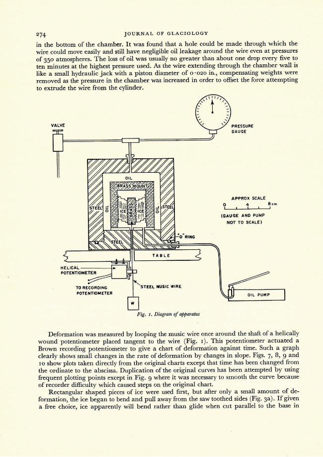
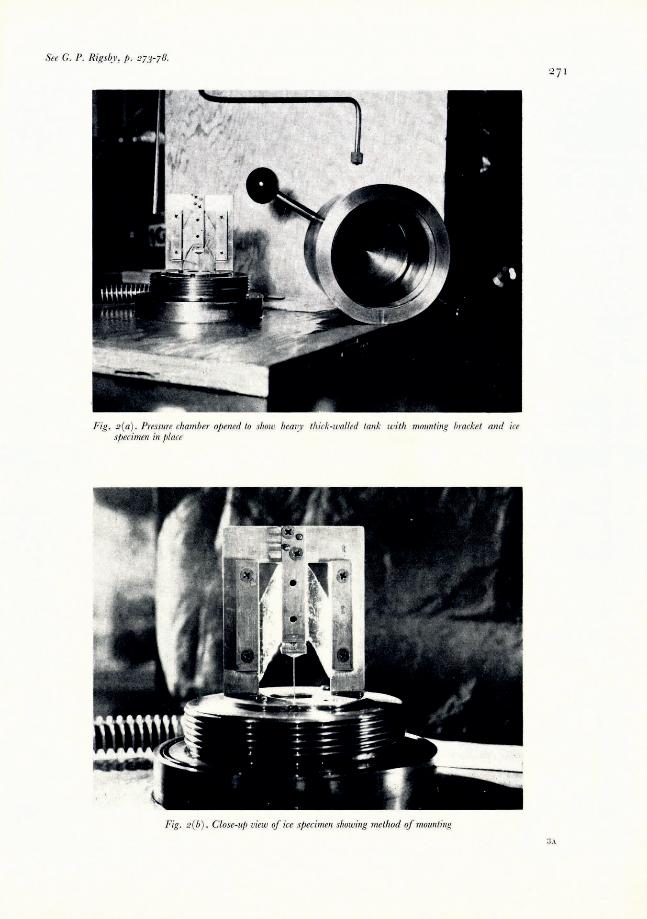
dimensions, with walls approximately 2'5 cm. thick (Fig. 2a, p. 271 ). Oil pressure was applied through a fitting at the bottom of the cylinder by a hydraulic jack, and a means of bleeding the system of air was provided by another fitting at the top. A pressure gauge was also put into the pressure line (Fig. I).
A brass mount was designed so that two pieces of ice were deformed at the same time, thus preventing friction due to sliding of metal on metal or metal on ice (Fig. 2b). Brass guides were used along the center to keep the center pull straight. The two pieces of ice were cut from a single crystal and oriented so that the c-axis of each piece was always as close to perpendicular to the applied force as possible. The specimens were made double sized, then split, and one half rotated before mounting for symmetry of angles and shape. The ice-brass contact was saw-toothed in order to prevent slippage. A small amount of ice water was placed on the contacts with an eye dropper to freeze the ice to the mount, any excess being scraped off. The dimensions of each of the two specimens were approximately I t in. X t in. X! in. (3 .81 cm. X I '27 cm. x o·64 cm.) .
The force for deforming the ice was transmitted to the specimen mount by means of a o . 020 in. (0 ' 508 mm.) steel music wire through a hole of approximately the same diameter
273 3B
274 JOURNAL OF GLACIOLOGY
in the bottom of the chamber. It was found that a hole could be made through which the wire could move easily and still have negligible oil leakage around the wire even at pressures of 350 atmospheres. The loss of oil was usually no greater than about one drop every five to ten minutes at the highest pressure used. As the wire extending through the chamber wall is like a small hydraulic jack with a piston diameter of 0 '020 in., compensating weights were removed as the pressure in the chamber was increased in order to offset the force attempting to extrude the wire from the cylinder.
VALVE
TABLE
TEEL MUSIC WIRE
POTENTlOMETER
Fig. I. Diagram of apparatus
o I
PRESSURE GAUGE
APPROX SCALE
4 I
(GAUGE AND PUMP
NOT TO SCALE)
8nn I
Deformation was measured by looping the music wire once around the shaft of a helically wound potentiometer placed tangent to the wire (Fig. I). This potentiometer actuated a Brown recording potentiometer to give a chart of deformation against time. Such a graph dearly shows small changes in the rate of deformation by changes in slope. Figs. 7, 8, 9 and 10 show plots taken directly from the original charts except that time has been changed from the ordinate to the abscissa. Duplication of the original curves has been attempted by using frequent plotting points except in Fig. 9 where it was necessary to smooth the curve because of recorder difficulty which caused steps on the original chart.
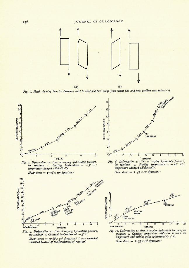
Rectangular shaped pieces of ice were used first, but after only a small amount of deformation, the ice began to bend and pull away from the saw toothed sides (Fig. 3a) . If given a free choice, ice apparently will bend rather than glide when cut parallel to the base in

SHEAR DEFORMATION OF SINGLE ICE CRYSTALS
relatively narrow pieces, although some slippage is required, of course, to bend the crystal. This phenomenon has been observed several times in other experiments. The difficulty of bending and pulling away from the mount was largely eliminated by cutting crystals in the shape ofa parallelogram having angles of 60° and 120°, as in Fig. 3b, and by deforming them in the direction which tends to make rectangles of the original parallelograms. Crystals cut with angles of 30° and 150° were tried, but offered no advantage as the total shearing strain was only about 30°. Fig. 2b shows the crystal cut at 30° and 150° and illustrates how the ice is mounted before the cylinder is put in place.
Mter the specimen was prepared and frozen to the mounts, it was then placed in the pressure chamber. The chamber was filled with oil and all pressure lines connected, and the whole system was bled to remove air bubbles. The pressure chamber was then placed inside a box containing a fan and a heating coil controlled by a thermoswitch. The whole apparatus was placed in a cold room at -5°C. The air temperature in the box cycled between -2.8° C. and -3' 2° C., each cycle usually being no more than three to five minutes long. No temperature change due to this air temperature cycle could be detected inside the thick steel case.
After the temperature came to equilibrium (usually overnight), a weight was added to the wire supplying the force for deformation. When a pressure increase or decrease was required, it was necessary to remove the weight, change the pressure and wait until the temperature reached the desired value, since an adiabatic temperature change in the oil occurred with a change in pressure. I
Fig. 4 (p. 272) shows a specimen which was deformed far enough to pull away from the sides of the mount. In some experiments, the ice crystal bent more than goO at each end. The strain rate increases as the crystal bends, showing that the effective length of glide is shortened and that it takes less force to bend the crystal than to deform it by gliding only. In Fig. 4, the lines paralleling the sides of the crystal are caused by differential movement on basal glide planes. Because of surface unevenness, these lines are easiest seen on specimens before the sides have been polished, and leave no doubt that they are traces of the translation plane. The planes can still be brought out on polished sections by special lighting techniques (Fig. 6, p. 272). Apparently the crystalline structure is disturbed along these planes, though not cracked or broken.
Sometimes differential movement occurred primarily on very few glide planes giving a final step-like appearance (Figs. 4 and 5). When this happened the results were not used as it seemed desirable to have a more even distribution of differential movement on the glide planes. It was also seen under the microscope that bending similar to that described above but on a smaller scale occurred at each step (Fig. 6). Uneven distribution of gliding always occurred to some extent, and it is believed that this was the cause of the wide differences in the load required to keep the deformation at a satisfactory rate. Such differences make it difficult to compare one sample with another. Small orientation differences also probably affected the rate of deformation, but it is thought that differences in orientations were no more than one or two degrees. Apparently once a crystal starts to deform by gliding on certain planes, there is little change in the number of active glide planes throughout the experiment. This gives reliable information for any change of conditions made on that crystal, but little correlation can be made from one crystal to another. Because of the limited distance one crystal could be deformed, no single crystal could be subjected to the various temperature and pressure combinations, but it would be desirable in order to correlate the effects properly.
EXPERIMENTAL RESULTS
The experiment was first performed at - 5° C. by changing the hydrostatic pressure and ignoring the adiabatic temperature change in the oil. A marked change in deformation rate
JOURNAL OF GLACIOLOGY
i i i
(a) (b) Fig. 3. Sketch showing how ice specimens start to bend and pull away from mount (a) and how problem was solved (b)
22
20
18
- 16 E .5. 14 z Q 12 l;i ~ 10
~ 8 w o 6
4
, 0''''
2
°0~~--~~----~2~----~3~----~4~----~ 5
TIME{tv)
Fig. 7. Deformation vs. time at varying hydrostatic pressure, ice specimen I. Starting temperature = - 5° C.; temperature changed adiabatically.
E 16
.5.1 § l;i 12
~ 10
~ 8 w o 6
Shear stress = 2 ' 56 X I06 dynes/cm.'
4 5 6 7 TIME{hrj
8 9 10
Fig. 9. Deformation vs. time at varying hydrostatic pressure, ice specimen 3. Constant temperature at - 5° C.
Shear stress = 3·68 x I06 dynes/cm.' (curve sOTTU!what smoothed because of malfunctioning of recorder)
E .5. z 0
~ ::;; a:: 0 LL w 0
14
12
8 ,~ ,0
6 ,;.'" 4 '1><
"- TIME BREAK
o'~
2 "-,,j'>
\O,ftI
00 2 3 4 5 6 7 8 9 10 . TlMFlhrl
Fig. 8. Deformation vs. time at varying hydrostatic pressure, ice specimen 2. Starting temperature = - 20" C.; temperature changed adiabatically.
Shear stress = 2' 43 X 106 dynes/cm.'
8
E .5. 6 z o ~ 4 ::;; a:: o t::. 2 22hr o TIME BREAK
0~1 ~~3~~5~~7=-~~9~~1~1~~13~~1~5-L~17~-7.19~~2 1 (after initiat sfor1) TIME{hr)
Fig. 10. Deformation vs. time at varying hydrostatic pressure, ice specimen 4. Constant temperature dijJerence between ice temperature and melting point approximately 3" C.
Shear stress = 2' 55 X 106 dynes/cm. >

SHEAR DEFORMATION OF SINGLE ICE CRYSTALS
was seen immediately upon changing the pressure (Fig. 7). It was soon realized that the temperature of the oil was raised considerably by the increase in pressure. A thermocouple was then mounted in the apparatus and placed about i in. (3 mm.) from the ice. By this means the temperature rise was measured to be about 4 0 C . with a pressure increase of 350 atmospheres. According to the data availal;lle Z the melting point of ice at this pressure should have been lowered more than 2 ' 5 0 C. These data indicate that the oil actually reached the melting point of the ice although there were no visible effects of melting on the sample, possibly because the temperature dropped rapidly owing to the large heat capacity of the thick steel walls of the pressure cylinder and the brass mount in contact with the ice. The same experiment was performed at _20
0 C. and little if any change of deformation rate was detected with pressure change, apparently because the melting point was not approached (Fig. 8).
It had been discovered in an earlier experiment that with a constant force at I atmosphere pressure, a single ice crystal gliding on basal glide planes reached an almost constant rate of deformation after the initial slow start, and that the force could be removed overnight without affecting the rate upon resuming the experiment. The force could be applied as much as several days later, and the same deformation rate continued without repeating the initial slow start. This showed that the deformation can be discontinued during the time necessary for the oil temperature to reach equilibrium with the air temperature in the box after a change of hydrostatic pressure without affecting the validity of the experiment.
Next, the deformation of a specimen was attempted at as constant a temperature as possible, varying only the pressure. This required several hours delay with weight removed after each change of pressure. Fig. 9 shows that there is an increase in rate of deformation with an increase of hydrostatic pressure. The shear strain rate at 293 atmospheres is about double the rate at I atmosphere pressure, except for the last drop in pressure which is believed to be caused by the bending described above. Table I gives the shear strain rates, shear stress and viscosity for each change of pressure on each sample.
These results indicated the desirability of performing the experiment at a constant temperature differential between the ice temperature and its melting point at the chosen pressure. About 30 C. below the melting temperature was selected as suitable because it
TABLE I. SHEAR STRESS, SHEAR STRAIN RATE, AND VISCOSITY AT DIFFERENT PRESSURES ON ICE SPECIMENS
Specimen Temperature Pressure Shear Stress X 10 -6 Shear Strain Rate Viscosiry X 10- 10
(OC.) (atm.) (dyne cm.-2 ) X 105 (sec. -I) (poise)
-S I 2'S6 6'96 3. 68 -I to -S 306 2'S6 I4'S3 1'76 -S to -8 I 2'S6 9'°9 2·82 -I to-s 306 2'S6 15"33 1'67 -S to -8 2'S6 10 ·87 2'36
2 -20 I 2'43 I '7S 13 ' 88 2 -16 to -20 293 2'43 3' 14 7'74 2 -20 to -23 2'43 4'20 5"78 2 - 20 2'43 S'21 4. 66 2 -16 to -20 293 2'43 9 ' 31 2·61
3 -S 293 2'76 S'74 4'80 3 -S I 3.68 2'72 13'S I 3 -S I 3.68 2'40 IS'32 3 -S 293 3. 68 4'76 7'72 3 -S 293 3. 68 S' 91 6 ' 22 3 -S 3' 68 5"20 7'°7
4 -3'1 I 2'SS I 'S6 16'3S 4 -S'I 27° 2'SS 1'13 22'S8 4 -S'3 27° 2' SS 0. 629 40 'S6 4 -3'3 2'SS 0.631 4° ' 43

JOURNAL OF GLACIOLOGY
seemed desirable to work as close to the melting point as possible. A temperature of approximately -3° C. was maintained in the oil at I atmosphere pressure and -So C. (the laboratory temperature) at 270 atmospheres pressure. The calculated melting temperature for ice at this pressure is -2' 15° C. Fig. la shows the effect on the deformation rate with pressure change at a constant difference between ice temperature and melting point. It can be seen that there is no sharp change in slope accompanying the pressure change contrary to the change in slope observea in the other two experiments performed at or near the same temperatures. Experiment 4, Table I shows a decrease in shear strain rate from 1'13 X 10-5 sec.-I to 0.629 X 10⁻⁵ sec.-I at the same pressure of 270 atmospheres, but these are only average values between time breaks. The slope as seen in Fig. la has little if any discontinuity at the time break, but it gradually changes from the beginning to the end of the experiment, apparently independent of the pressure changes.
It is believed that the accuracy of the readings taken from the recorder is better than 0'001 cm.
CONCLUSIONS
It is concluded from the results of these experiments that the shear strain rate for plastic deformation of single ice crystals deforming by gliding on the basal glide planes is practically independent of hydrostatic pressure when the difference between ice temperature and melting point is maintained at a constant interval.
ACKNOWLEDGEMENTS
The writer was a member of the scientific staff of the Snow, Ice and Permafrost Research Establishment, Wilmette, Illinois, during the time these experiments were carried out and appreciation is hereby expressed to Dr. Henri Bader and the members of his staff for their help and advice. The writer is also indebted to Professor R. P. Sharp for reading through and commenting on the manuscript.
MS. received 10 May 1958
REFERENCES
1. Zemansky, Mark W. Heat and Thermodynamics. 2nd Ed., New York, McGraw-Hill, 1943· 390 p. 2. Dorsey, N . Ernest. Properties of Ordinary Water-Substance. New York, R einhold Publishing Corp. , 1940.673 p.
See C. P. R£gsb)', f). 273-78.
Fig . 2(a). Pressure chamber o/Jelled to show heaD.-V thick-walled lank with mounting bracket and ice sjJecimen ill place
Fig . 2(b) . Close-ut) view oJ ice s/Jecimen showing method oJ mounting
'27 1

Fig. 4. Deformed ice ClJstal showing bending alld nl/eI'en gliding
Fig. 5. T wo crystals d~/ormed at the same time in the /Jressllre chamber, showing greatest movement along only a f ew /)lanes
Fig . 6. Photomicrograj)h of diformed ice cl)'stal showing bending of glide /)lalles at small offsets. Sj){cimell has been jiOlished. bllt ceria in glide /)Ialles show b) , IIsing s/Jeciallighting teclmiques for pizotogral"izing